Article

Cavitation–Silt Erosion Behavior and Failure Mechanism of an HVOF-Sprayed WC-Cr3C2-Ni Coating for Offshore Hydraulic Machinery

1
College of Engineering, Nanjing Agricultural University, Nanjing 210031, China
2
College of Mechanics and Materials, Hohai University, Nanjing 211100, China
3
College of Energy and Electrical Engineering, Hohai University, Nanjing 211100, China
*
Authors to whom correspondence should be addressed.
J. Mar. Sci. Eng. 2022, 10(10), 1341; https://doi.org/10.3390/jmse10101341
Submission received: 19 August 2022 / Revised: 10 September 2022 / Accepted: 13 September 2022 / Published: 21 September 2022
(This article belongs to the Special Issue Failure Analysis of Marine Structure)

Abstract

:
WC-Cr3C2-Ni coatings are a vital class of hard ceramic/cermet coatings with potential applications as wear-resistant materials. However, their erosion wear behavior in 3.5 wt.% sodium chloride medium (SCM) remains largely unexplored. The present study investigated the cavitation–silt erosion (CSE) behavior in 3.5 wt.% SCM of WC-Cr3C2-Ni coatings sprayed with high-velocity oxygen–fuel (HVOF) under different flow velocities (FVs) and sand concentrations (SCs). Comparing the WC-Cr3C2-Ni coating with the 1Cr18Ni9Ti stainless steel, the first possessed superior CSE resistance in 3.5 wt.% SCM in a full range of FV and SC. Meanwhile, the coating appeared more influenced by FV and less influenced by SC, which was indicated by the fact that the amplification of VLR value (377.1%) when the FV ranged from 23.4 to 41.9 m·s−1 was larger than that (129.8%) when the SC increased from 10 kg·m−3 to 35 kg·m−3. With increasing FV and SC, the CSE process of the WC-Cr3C2-Ni coating in 3.5 wt.% SCM mainly included the discontinuous corrosion product films, erosion pits, fracturing of hard-phase grains, and micro-cutting of soft binder matrix, as well as crater formation and coating spalling.

1. Introduction

Ocean power generation is an effective way to tackle energy shortage. However, many flow-handling components of hydraulic machinery (e.g., runner blade, guide vane, and volute) in ocean power generation systems are subjected to severe damage in the processes of corrosion and cavitation–silt erosion (CSE), which hinders the exploitation and utilization of ocean energy [1,2,3]. The degree of damage to the flow-handling components not only correlates with the stability and permanence of the materials on the surface, but also hinges on the structural design and the running conditions of hydraulic machineries, including water head, fluid temperature, pH, flow velocity (FV), sand diameter, and sand concentration (SC) [4,5,6]. Long and effective life is an urgent requirement for offshore hydro-turbines and pumps that run under multi-phase flow conditions, including complex CSE mechanisms, high ultrasonic cavitation, mechanical stresses, and electrochemical corrosion [7,8,9].
WC-based hard metals are favored for their great mechanical strength and considerable toughness and chemical stability that can be regulated by the adjustments of the type, grain size, and content of hard phases as well as binder phases, which often serve as erosion wear, corrosion, and tribocorrosion resistant materials [10,11,12,13]. However, there is still room for improvement to address the problems of the high cost and limited size of high-performance WC-based hardmetals. On account of the large-area preparation, high production efficiency, and cost-efficiency of thermal spraying techniques, as well as the preferential occurrence of corrosion and CSE on the surface, thermal-sprayed WC-based ceramic/cermet coatings show great potential for achieving a high erosion wear and corrosion-resistant surface for flow passage components of hydraulic machinery in ocean power generation systems [14,15,16,17]. Especially, in the case of high-velocity oxygen–fuel (HVOF) sprayed WC-based ceramic/cermet coatings, the oxidation and decarburization of the WC phase during the coating preparation process under high-temperature combustion conditions can be effectively suppressed owing to the low flame temperature of 1900–3000 K as well as the high flame velocity of ~550 m·s−1, which guarantees the great toughness and mechanical strength and the resultant erosion wear and corrosion resistance [18,19,20].
As for the HVOF-sprayed WC-Cr3C2-Ni coatings, detailed studies of their damage behavior and failure mechanisms under various erosion wear, corrosion, and cavitation erosion conditions indicate their potential for practical applications in ocean power generation systems. It turns out that HVOF-sprayed WC-Cr3C2-Ni coating possesses lower friction coefficient as well as higher sliding wear resistance, especially at temperatures over 700 °C, at various load or sliding speed conditions compared to the WC-CoCr coating, which mainly depends on two factors, i.e., the well-distributed thin oxide scale and the double-decker shell-core microstructure for the WC-Cr3C2-Ni coating [21,22,23,24]. In pursuit of high bond strength and hardness as well as low porosity for enhanced sliding wear resistance, improvements have been made in the heat treatment of the WC-Cr3C2-Ni coating [25,26] and the optimization of the HVOF spray process [27,28]. However, other researchers discovered that the sliding wear resistance of the WC-Cr3C2-Ni coating was not influenced significantly by the content of the alloying element Cr when the counterpart was WC-Co hardmetal [29]. With regard to the corrosion and abrasive wear, HVOF sprayed with WC-Cr3C2-Ni coating exhibited higher abrasive wear resistance at various load and SC conditions [30] as well as almost the same ability to resist corrosion in 3 wt.% SCM [31], as compared to AISI 304 stainless steel. Moreover, WC grain size, feedstock powder characteristics and thermal spraying process had notable influence on enhancing the resistance against abrasive wear for the WC-Cr3C2-Ni coating [32,33]. Researchers also pointed out that HVOF-sprayed WC-Cr3C2-Ni coating possessed superior resistance against cracking [34] and can be an ideal strategy for preventing the substrates from cavitation erosion damage at various FV and environmental conditions [35,36,37]. As stated above, although the existing studies have shown a positive effect on various properties, they contribute little to the feasibility and reliability of applying the WC-Cr3C2-Ni coating in complex multi-phase flow conditions, including corrosion and CSE. Therefore, this study aims to investigate the CSE behaviors of HVOF-sprayed WC-Cr3C2-Ni coating in 3.5 wt.% SCM under different FVs and SCs.
In the present work, WC-Cr3C2-Ni cermet coatings were fabricated by the HVOF spraying method. Then, the coatings were subjected to a slurry containing 3.5 wt.% SCM, in order to assess their CSE properties via a rotating disk rig facility rather than the jet impingement facility, to more closely simulate the operating condition of rotating components, such as runner blades. This work provides anticipative help in understanding the effects of FV and SC on CSE behaviors of the coatings in 3.5 wt.% SCM. Meanwhile, CSE mechanisms of the coatings under various FVs and SCs in 3.5 wt.% SCM were elucidated on the basis of the eroded surface micro-morphologies.

2. Experimental Procedure

In this study, the feedstock powder used for spraying was a commercially available WC-Cr3C2-Ni powder obtained from Zhangyuan Tungsten Co. Ltd., comprising 73 wt.% WC, 20 wt.% Cr3C2, and 7 wt.% Ni. As shown in Figure 1, the feedstock powder particles possessed a spherical and porous structure with a grain size range of 15–45 μm. 1Cr18Ni9Ti stainless steel, with nominal composition in wt.% of 69.63 Fe, 17.65 Cr, 10.23 Ni, 1.17 Mn, 0.75 Si, 0.46 Ti, 0.075 C, 0.021 P, and 0.0069 S, was selected as the substrate material for spraying and as the comparative material for CSE tests, due to its wide applications in offshore hydraulic machinery. Prior to the coating fabrication, the pre-treatment of the substrates with a dimension of 60 × 30 × 5 mm3 was employed to ensure adequate bonding of the coating, which included cleaning in acetone, drying in hot airflow, and sandblasting with 30 mesh Al2O3 grits. Subsequently, WC-Cr3C2-Ni feedstock powders were sprayed onto the substrates with the help of the Tafa-JP8000 HVOF spraying equipment manufactured by Praxair Co. Ltd. (Danbury, CT, USA). The specific HVOF spraying parameters were as follows: (a) flow rate of kerosene was 23.4 L·h−1, (b) flow rate of oxygen was 906 L·min−1, (c) spray distance was 0.38 m, (d) powder feeding rate was 0.92 g·s−1, (e) scanning speed of spray gun was 16.8 m·min−1. Argon was selected as the carrier gas, with a flow rate of 652 L·h−1. The as-sprayed coatings were deposited as thick as ~350 μm through 14 fixed spraying passes. The deposition efficiency of the as-sprayed coatings was approximately 47%.
An X-ray diffractometer (XRD, Philips PANalytical X’pert) with a Cu Kα anode and a field-emission scanning electron microscope (FE-SEM, FEI Quanta 250F, Hillsboro, OR, USA) were employed to analyze phase constitutions as well as to examine surface and cross-sectional micro- morphologies of the WC-Cr3C2-Ni feedstock powder and as-sprayed coating. During XRD data acquisition, the voltage, current, scanning, velocity, scanning step and diffraction range were set as 40 kV, 150 mA, 5°·min−1, 0.02°, and 20–90°, respectively. Energy dispersive spectroscopy (EDS, Oxford X-Max, Oxfordshire, UK) was utilized to determine the types and contents of the elements on cross-sections and eroded surfaces of the as-sprayed coating. Porosity testing was conducted on FE-SEM cross-sectional micro-morphologies of the as-sprayed coating under magnification of ×1000 with the help of an image analysis method, which was in accordance with the standard ASTM E2109-01 [38]. A nanoindentation method was used on the cross-section to assess the nanomechanical properties of the as-sprayed coating. The elastic modulus (E) and hardness (H) of the coating were evaluated via an ultra- nanoindentation tester (CSM UNHT, Peseux, Switzerland) under a strain rate of 0.05 s−1 and a loading rate of 10 mN·s−1. After attaining the maximum load of 300 mN, the hold time of the Berkovich indenter was 5 s. Then, the indenter was unloaded at a rate of 10 mN·s−1. The coating specimens were subjected to 15 repetitions of porosity and nanoindentation testing to ensure the repeatability and accuracy of the data.
The corrosion resistance of the coating and the comparative stainless steel was assessed using potentiodynamic polarization tests, which were performed on a CS 2350H electrochemical workstation using a typical three-electrode cell system. The saturated calomel electrode (SCE) and platinum electrode were used as the reference electrode and counter electrode, respectively. A reasonable time of 1 h was reserved for the immersion of specimens (1 cm2 exposed area) in 3.5 wt.% SCM at room temperature, aiming to reach an equilibrium state of the open-circuit potential. Then, potentiodynamic polarization tests were implemented by scanning the potential at a rate of 0.5 mV·s−1. Superimposing and extrapolating the straight lines along the linear part of the anodic and cathodic polarization curves were utilized to acquire the electrochemical characteristic parameters, comprising corrosion current density (icorr) and corrosion potential (Ecorr). The specimens were subjected to 3 rounds of specimen testing to guarantee the accuracy and repeatability of the data.
CSE tests were conducted via a rotating disk rig facility equipped with a circulation system, as illustrated in Figure 2a. The schematic illustrations of the rotating disk compartment for CSE tests and the corresponding specimen size are represented in Figure 2b,c, respectively. It is obvious that six bolt cavitators (Φ 5 mm × 5 mm) were fixed in the actinomorphic holes along the periphery of the rotating disk. For reducing the flow round within the chamber and maintaining the pressure at 0.1 MPa in the chamber, 24 sets of equal-interval actinomorphic baffles were inserted on either side of the rotating disk. The high-velocity sand-containing seawater in the Qinshan area of China contained an average sand concentration of 3~6 kg·m−3 with a maximum of 12 kg·m−3 and an average flow velocity of 0.9~1.8 m·s−1 with a maximum of 4 m·s−1 [39,40]. In order to predict the performance of the HVOF-sprayed WC-Cr3C2-Ni coating for application in offshore hydraulic machineries, the operating parameters stated in Table 1 and 3.5 wt.% SCM were chosen to simulate severe working environments run under high-CSE conditions in corrosive seawater. Prior to the CSE tests, the pre-treatment of the specimens was employed, which included grinding with 240–2000# SiC abrasive papers, polishing with 1.5 μm diamond pastes, cleaning ultrasonically in acetone, drying in hot air, weighing with an analytical balance to a precision of 10−1 mg, and imbedding in the rotating disk. Then, CSE tests were implemented for 6 h in a slurry containing 3.5 wt.% SCM and commercial quartz sand with a grain size range of 30–70 mesh. The cooling circulation system was employed to maintain the temperature of the slurry at 25 ± 5 °C. For ensuring data accuracy, new quartz sand and three parallel specimens for both the coating and the comparative stainless steel were used at each operating parameter. After the tests, the specimens were re-treated following the procedure for obtaining the mass changes, which was same as the pre-treatment of the specimens before the tests. The volume losses were computed by dividing the mass losses by the densities of the specimens. Thus, the volume loss rates (VLR) and corresponding FE-SEM micro-morphologies of the eroded surfaces were mainly considered for revealing the effects of FV and SC on the CSE behavior in 3.5 wt.% SCM of the HVOF-sprayed WC-Cr3C2-Ni coating.

3. Results and Discussion

3.1. Microstructure, Nanomechanical Properties, and Potentiodynamic Polarization

Figure 3 shows the FE-SEM images of the coating in the cross-sectional view and the corresponding results of EDS analysis. From Figure 3a,b, the coating in as-sprayed state presented a clear interface between the substrate and coating, as well as a dense structure with average porosity of 1.15% and thickness of ~350 μm. When the feedstock powders in molten state flew at high speed and severely struck the substrate, the sufficient deformation and anchoring effects were beneficial for decreasing porosity and ensuring high bond strength [37]. At higher magnifications, i.e., 2000× (Figure 3c) and 5000× (Figure 3d), microstructural features of the coating were captured in more detail. Moreover, the EDS results, as exhibited in Figure 3e,f, indicated that the dark grey-contrasted regions (denoted as Point A) and the light grey-contrasted regions (denoted as Point B) corresponded to chromium carbide and tungsten carbide, respectively. Although a great amount of tungsten carbide combined well with chromium carbide, imperfections including pores and microcracks were still presented in the as-sprayed state due to the temperature gradient that resulted from the overlapping of poor molten particles [41].
Figure 4 represents the phase constitutions of the feedstock powder and the coating [37], in which the XRD peaks corresponding to WC (JCPDS No. 51-0939), Cr3C2 (JCPDS No. 35-0804), Ni (JCPDS No. 04-0850), and (W,Cr)2C were identified. It was noted that WC was the major phase, while Cr3C2 and Ni appeared as minor phases in the feedstock powder. After the HVOF spraying process, the peaks assigned to WC, Cr3C2, and Ni became weaker and the peaks assigned to (W, Cr) 2C appeared in the coating, which was in accordance with previous studies reported in the literature [42,43]. This revealed that Cr3C2 was unstable along with Ni matrix in molten state, during which WC, Cr3C2, and Ni underwent sufficient solid-state reactions, which was mainly derived from two factors, i.e., sufficiently high temperature and complete combustion [21,44].
The nanomechanical properties of the WC-Cr3C2-Ni coating and the 1Cr18Ni9Ti stainless steel, including the ratio of H and E (i.e., H/E) as well as H3/E2, were illustrated in Figure 5. It can be noted that the H/E and H3/E2 values of the WC-Cr3C2-Ni coating were about 1.5 and 8.7 times as large as those of the 1Cr18Ni9Ti stainless steel, respectively. This indicated that the coating may possess higher resistance to deformation in the erosion wear condition by comparison with the stainless steel. The high proportion of tungsten carbide phase, with hardness and elastic modulus values of about 24 GPa and 680 GPa [45,46], was considered favorable to the superior nanomechanical properties of the coating, although there were a few imperfections, including pores and microcracks in the coating, as compared to the stainless steel.
For long-term practical applications of HVOF-sprayed WC-Cr3C2-Ni coating in ocean power generation systems, evaluation of corrosion resistance was essential since the surface of the coating was exposed to localized corrosion in a seawater environment. Figure 6 depicts the potentiodynamic polarization curves in 3.5 wt.% SCM of the WC-Cr3C2-Ni coating and the 1Cr18Ni9Ti stainless steel, which were closest to the average of three electrochemical measurements. The Ecorr values of the stainless steel and the coating were established to be −204 mV and −517 mV vs. SCE, respectively. In the meantime, the stainless steel revealed icorr values as low as 39.5 nA·cm−2, compared to the coating (7650 nA·cm−2). From the perspective of the thermodynamics of corrosion, more negative values of Ecorr signified lower degrees of difficulty of corrosion. From the perspective of the kinetics of corrosion, smaller values of icorr signified lower corrosion rates [47]. Comparing the coating with the stainless steel, the former possessed a more negative value of Ecorr as well as a larger value of icorr. Thus, the coating revealed worse anticorrosion properties in 3.5 wt.% SCM, which was ascribed to two foremost factors. For one, the absence of imperfections and microstructural homogenization for the stainless steel can impede the occurrence of corrosion reactions. For the other, the passive nature of the stainless steel contributed to the high forming ability of passive film that prevented the infiltration of electrolytes and the initiation of corrosion defects [48,49,50,51].

3.2. Effects of FV and SC on CSE

Figure 7 displays the VLR of the WC-Cr3C2-Ni coating and the 1Cr18Ni9Ti stainless steel as a function of FV after CSE at 20 kg·m−3 in 3.5 wt.% SCM. After 6 h of CSE at FV of 23.4, 33.5 and 41.9 m·s−1, the WC-Cr3C2-Ni coating revealed VLR values of 0.056, 0.11, and 0.27 mm3·h−1, respectively, which were significantly inferior to those of the 1Cr18Ni9Ti stainless steel (3.23, 7.94, and 9.52 mm3·h−1). This disparity meant that the CSE resistance in 3.5 wt.% SCM of the WC-Cr3C2-Ni coating was superior to that of the 1Cr18Ni9Ti stainless steel when the FV ranged from 23.4 m·s−1 to 41.9 m·s−1, although the WC-Cr3C2-Ni coating possessed worse anticorrosion properties, as suggested by Figure 6. Except for this finding, the VLR values of the WC-Cr3C2-Ni coating and the 1Cr18Ni9Ti stainless steel after 6 h of CSE at the FV of 41.9 m·s−1 were 377.1% and 194.7% higher, respectively, than those after 6 h of CSE at the FV of 23.4 m·s−1. This phenomenon indicated that higher FV coupled with SC of 20 kg·m−3 and 3.5 wt.% SCM caused more severe CSE degradation for both the WC-Cr3C2-Ni coating and the 1Cr18Ni9Ti stainless steel, and the coating appeared more influenced by FV, in contrast to the stainless steel. With increasing FV, the frequency of sand particle impingement, the kinetic energy conveyed by sand particles, the shedding frequency of cavitation, and flow turbulence all increased. These phenomena resulted in a wider availability of sand particles, a weaker shielding effect, and a larger stress on the specimen surface [52,53,54]. Additionally, higher FV can accelerate the conveyance of electroactive species and expand the electrochemical reaction’s surface area [55]. As a consequence, the CSE degradation for both the WC-Cr3C2-Ni coating and the 1Cr18Ni9Ti stainless steel was more severe owing to the abovementioned mechanisms, while the influence of FV on the 1Cr18Ni9Ti stainless steel was restricted owing to the alternation of depassivation and repassivation of passive film during CSE when the SC was 20 kg·m−3.
The VLR of the WC-Cr3C2-Ni coating and the 1Cr18Ni9Ti stainless steel as a function of SC after CSE at 20 kg·m−3 in 3.5 wt.% SCM is shown in Figure 8. After 6 h of CSE, significant difference between the WC-Cr3C2-Ni coating and the 1Cr18Ni9Ti stainless steel was detected when the SC were 10, 20, and 35 kg·m−3, in which the VLR values of the coating and the stainless steel were 0.072, 0.11, and 0.17 mm3·h−1, and 3.21, 7.94, 10.52, and mm3·h−1, respectively. In addition, the VLR values of the WC-Cr3C2-Ni coating and the 1Cr18Ni9Ti stainless steel after 6 h of CSE at SC of 35 kg·m−3 were 129.8% and 227.7% higher than those after 6 h of CSE at SC of 10 kg·m−3, respectively. These findings revealed that the WC-Cr3C2-Ni coating possessed superior CSE resistance in 3.5 wt.% SCM to that of the 1Cr18Ni9Ti stainless steel when the SC ranged from 10 to 35 kg·m−3, and higher SC coupled with FV of 33.5 m·s−1 and 3.5 wt.% SCM induced more severe CSE degradation for both the coating and the stainless steel. Two reasons could explain the more severe CSE degradation at higher SC. On the one hand, higher SC may have shortened the intervals among different sand particle impingements when the FV was 33.5 m·s−1, resulting in larger interactions between sand particles and specimen surface [53,56]. On the other hand, the increment of pressure and incipient cavitation number as well as the expansion of eroded area in the cavitation erosion zone at higher SC may have promoted the occurrence of cavitation erosion and the resultant higher abrasion rate [57]. Previous studies have pointed out that cavitation erosion had a positive relationship with SC [57,58]. It is also worth noting that contrary to the influence of FV on material degradation, the influence of SC on degradation of the coating was less than that of the stainless steel, which can be ascribed to the fact that the passive film on the surface of the stainless steel was insufficient to achieve repassivation under the continuous impingements of sand particles and cavitation bubbles as SC increased from 10 to 35 kg·m−3 at an FV of 33.5 m·s−1.
As illustrated in Figure 7 and Figure 8, it can be concluded from the lower VLR values of the WC-Cr3C2-Ni coating that the coating possessed superior CSE resistance in 3.5 wt.% SCM by contrast with the 1Cr18Ni9Ti stainless steel, which was related to three aspects. Firstly, the dense structure of the coating coupled with the strong bonding between the coating and substrate were conducive to the reduction of the cracking sources and the large-area exfoliation of the coating caused by the attack of multi-phase flow. Secondly, the element chromium in the coating made it possible to generate the passive film and accordingly, improved the CSE resistance in 3.5 wt.% SCM to some degree. Thirdly, the superior mechanical properties (e.g., H/E and H3/E2) of the coating ensured the higher resistance to impingements of sand particles and cavitation bubbles, especially under the condition of normal impact [59,60,61].
The FE-SEM images of surfaces for the WC-Cr3C2-Ni coating after 6 h of CSE in 3.5 wt.% SCM at 20 kg·m−3 and different FVs are depicted in Figure 9. It can be clearly seen from Figure 9a–c that there were great differences in the eroded surface micro-morphologies of the coatings when the FV ranged from 23.4 to 41.9 m·s−1. The appearance of rougher surface was characterized by smaller area of initially polished surfaces, more obvious scour marks and larger number and dimension of craters at higher FV. These observations indicated that more drastic physicochemical interaction processes and more serious material degradation took place during CSE at higher FV, which was in line with the measured VLR values, as revealed in Figure 7. It is evident from Figure 9(a1,a2) that only a small number of small erosion pits were scattered on the relatively flat surface. This meant at the FV of 23.4 m·s−1 coupled with the SC of 20 kg·m−3, most of the interfaces between hard-phase grains and soft binder matrix were strong enough to resist the impingement and abrasion of sand particles as well as the continuous attack of micro-jets or shock waves caused by the implosion of cavitation bubbles. By contrast, there were shallow erosion pits with a diameter of approximately 10 μm as well as slight fracturing of hard-phase grains and micro-cutting of soft binder matrix when the FV was 33.5 m·s−1 (Figure 9(b1,b2)), although most of the hard-phase grains and soft binder matrix were relatively intact. These findings contributed to the unevenness of the eroded surface and thereby resulted in the increase in the VLR value, as illustrated in Figure 7. When the FV increased to 41.9 m·s−1, there was a further increase in the dimension and depth of the craters. In addition, the gradual emergence of crater-shaped structures formed a somewhat interconnected groove structure on the eroded surface (Figure 9(c1,c2)). These phenomena were mainly ascribed to the more violent flow structure and propulsion by bubble-wall and micro-jet at the higher FV of 41.9 m·s−1 [62].
Figure 10 shows the analysis of surfaces for the WC-Cr3C2-Ni coating after 6 h of CSE in 3.5 wt.% SCM at 33.5 m·s−1 and different SCs through FE-SEM. From Figure 10a–c, it can be noted that similar ripple-shaped structures were observable on the coatings’ eroded surfaces at different SCs. Meanwhile, with higher SC, the depth and dimension of the ripple-shaped structures tended to become larger and the growth direction of the ripple-shaped structures followed the flow direction. These observations suggest that the increase in SC provided continuous interaction of sand particles and cavitation bubbles and thus prompted more serious material degradation, which was also supported by the measured VLR values, as referenced in Figure 8. At the SC of 10 and 20 kg·m−3, the microstructures of the coatings were relatively compact, characterized by extensive initially polished surfaces coupled with slight micro-cutting of the soft binder matrix, fracturing of hard-phase grains, and some shallow erosion pits with diameters of around 10 μm (Figure 10(a1,a2,b1,b2)). However, this compact microstructure was not preserved at an SC of 35 kg·m−3. After being subjected to 35 kg·m−3, the fracturing of hard-phase grains, as well as the micro-cutting and preferential removal of soft binder matrix were detected in Figure 10(c1,c2), leading to the coating spalling, on account of the smaller interval among different impingements caused by sand particles, as well as the higher degree of cavitation.
It is interesting to note from Figure 9 and Figure 10 that there was a bright white phase observable in all microstructures of the coatings after 6 h of CSE in 3.5 wt.% SCM at different FVs and SCs. EDS was applied to understand the composition of the bright white phase, and the analytical results were listed in Table 2. As the bright white structures were rich in O element, it is reasonable to infer those bright white structures were composed of oxide and the corrosion product films were distributed discontinuously on the eroded surfaces of the coatings. Comparisons on the EDS results of Points A, B, and C showed that bright white structures at lower FV and SC had higher O element content than others. This indicated that the corrosion product films were more easily destroyed by multi-phase flow at higher FV and SC, which may induce a higher abrasion rate. Therefore, based on the above-mentioned findings, the CSE failure mechanisms in 3.5 wt.% SCM of the coating with increasing FV and SC were caused by the discontinuous corrosion product films, the erosion pits, the fracturing of hard-phase grains, micro-cutting of soft binder matrix, and crater formation, as well as coating spalling.

4. Conclusions

In this work, we report the CSE behaviors in 3.5 wt.% SCM of HVOF-sprayed WC-Cr3C2-Ni coatings under different FVs and SCs via a rotating disk rig facility. The main conclusions of this work can be outlined as follows:
(1)
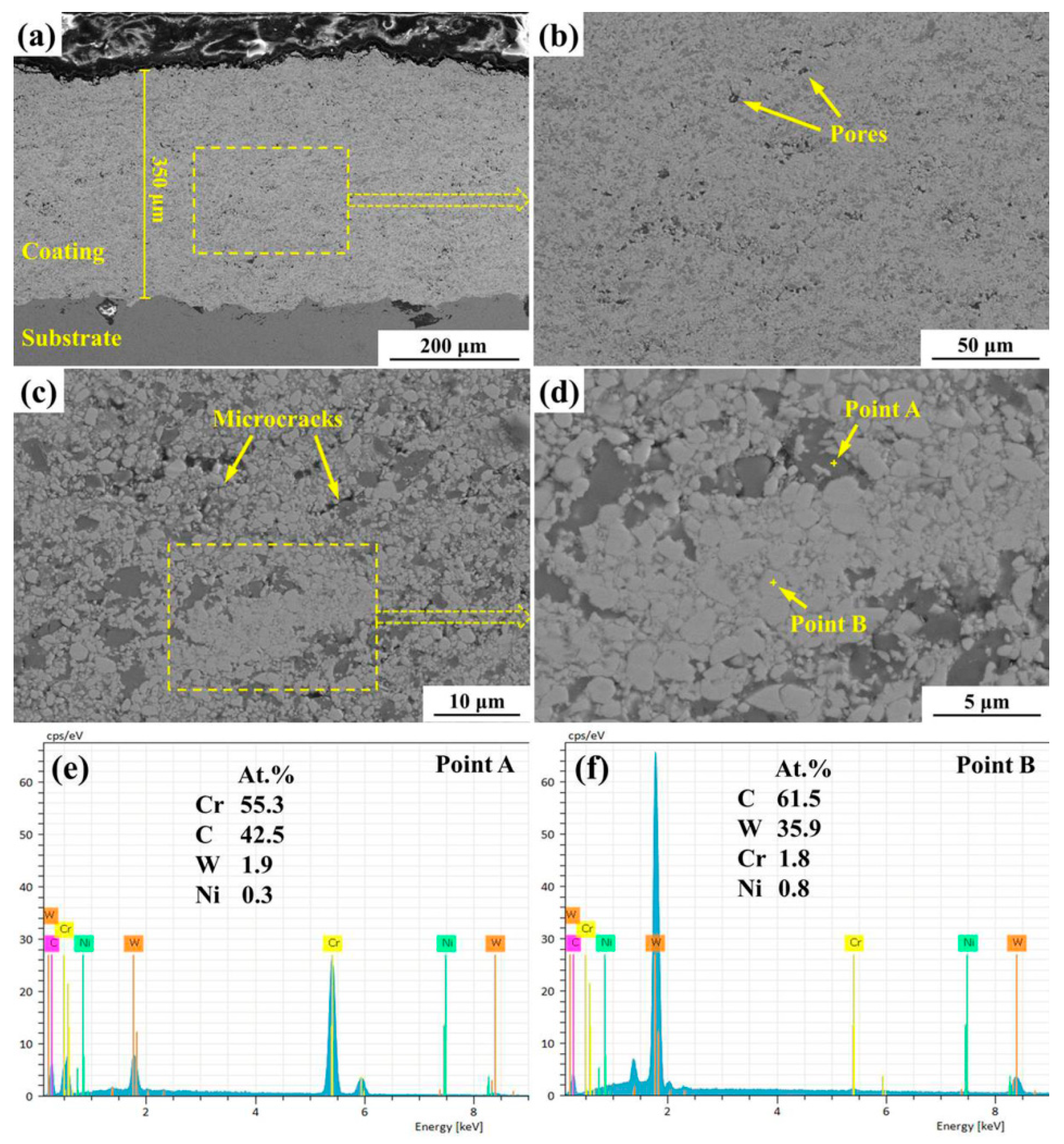
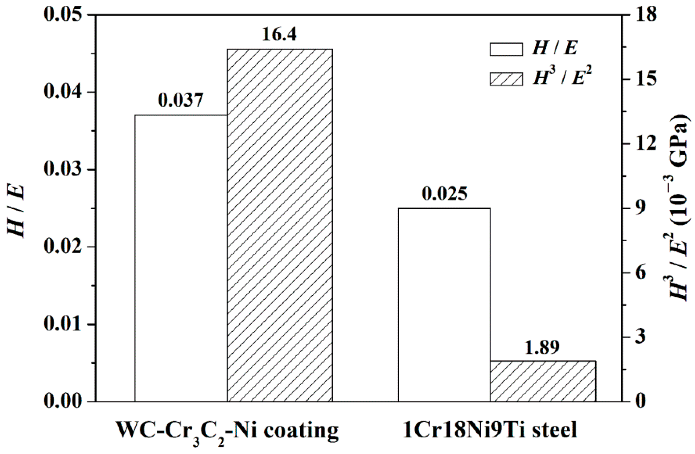
The WC-Cr3C2-Ni coating presented a dense structure with average porosity of 1.15% and thickness of ~350 μm, as well as good combination with the substrate. The H/E and H3/E2 values of the WC-Cr3C2-Ni coating were about 1.5 and 8.7 times as large as those of the 1Cr18Ni9Ti stainless steel, respectively.
(2)
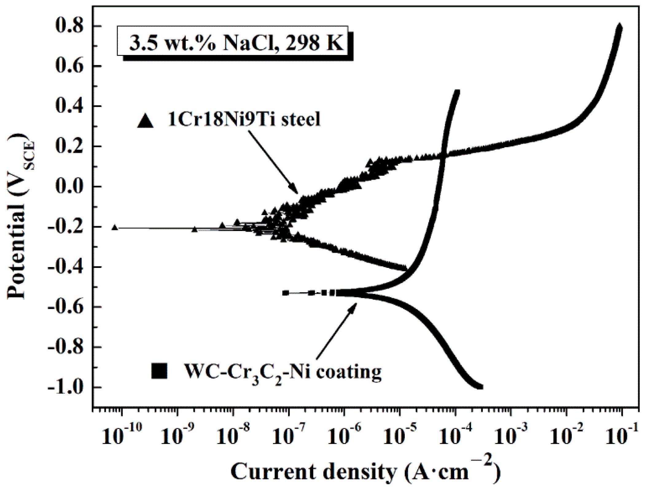
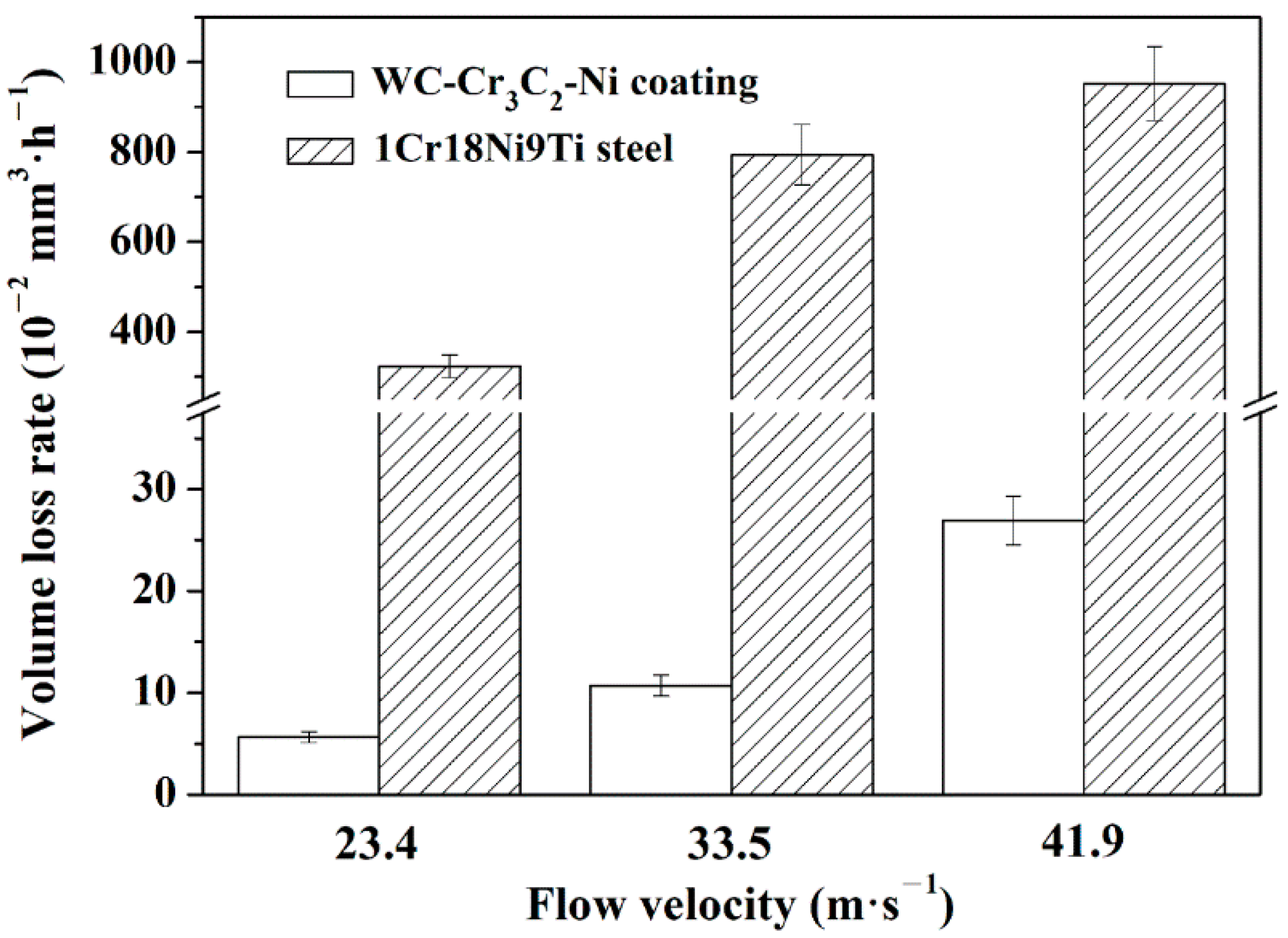
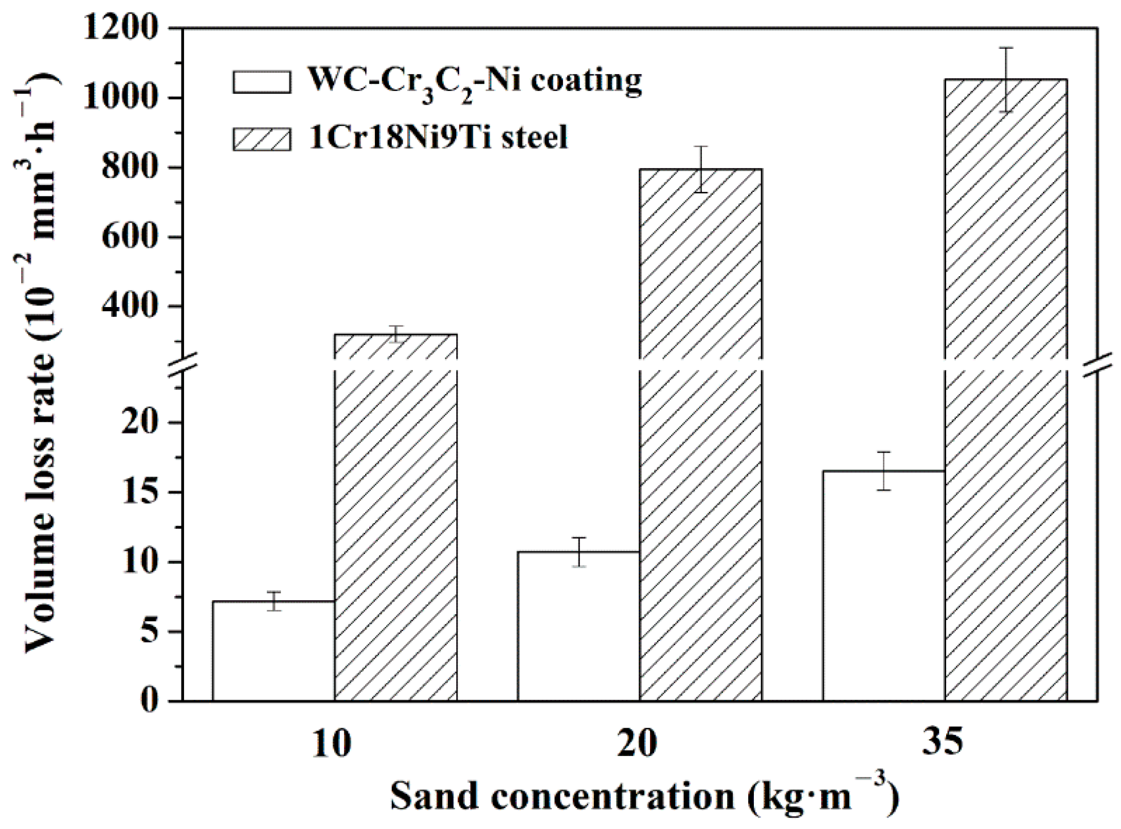
In contrast to the 1Cr18Ni9Ti stainless steel, the WC-Cr3C2-Ni coating possessed superior CSE resistance and worse anticorrosion properties in 3.5 wt.% SCM. Higher FV and SC caused more severe CSE degradations for both the coating and the stainless steel. By taking the amplification of the VLR value as the evaluation index, the coating (377.1%) appeared more influenced by FV in contrast with the stainless steel (194.7%), while the influence of SC on degradation of the coating (129.8%) was less than that of the stainless steel (227.7%).
(3)
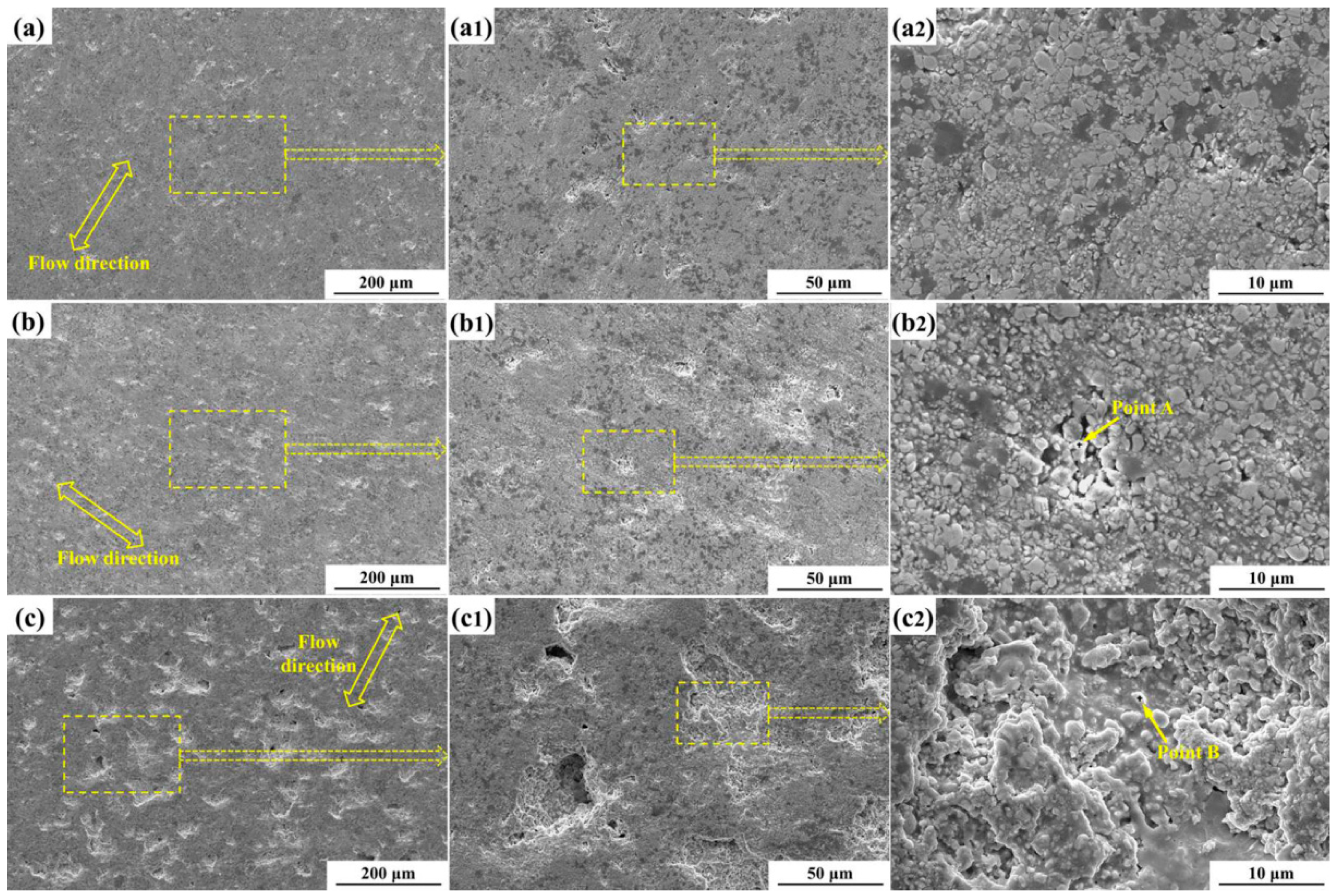
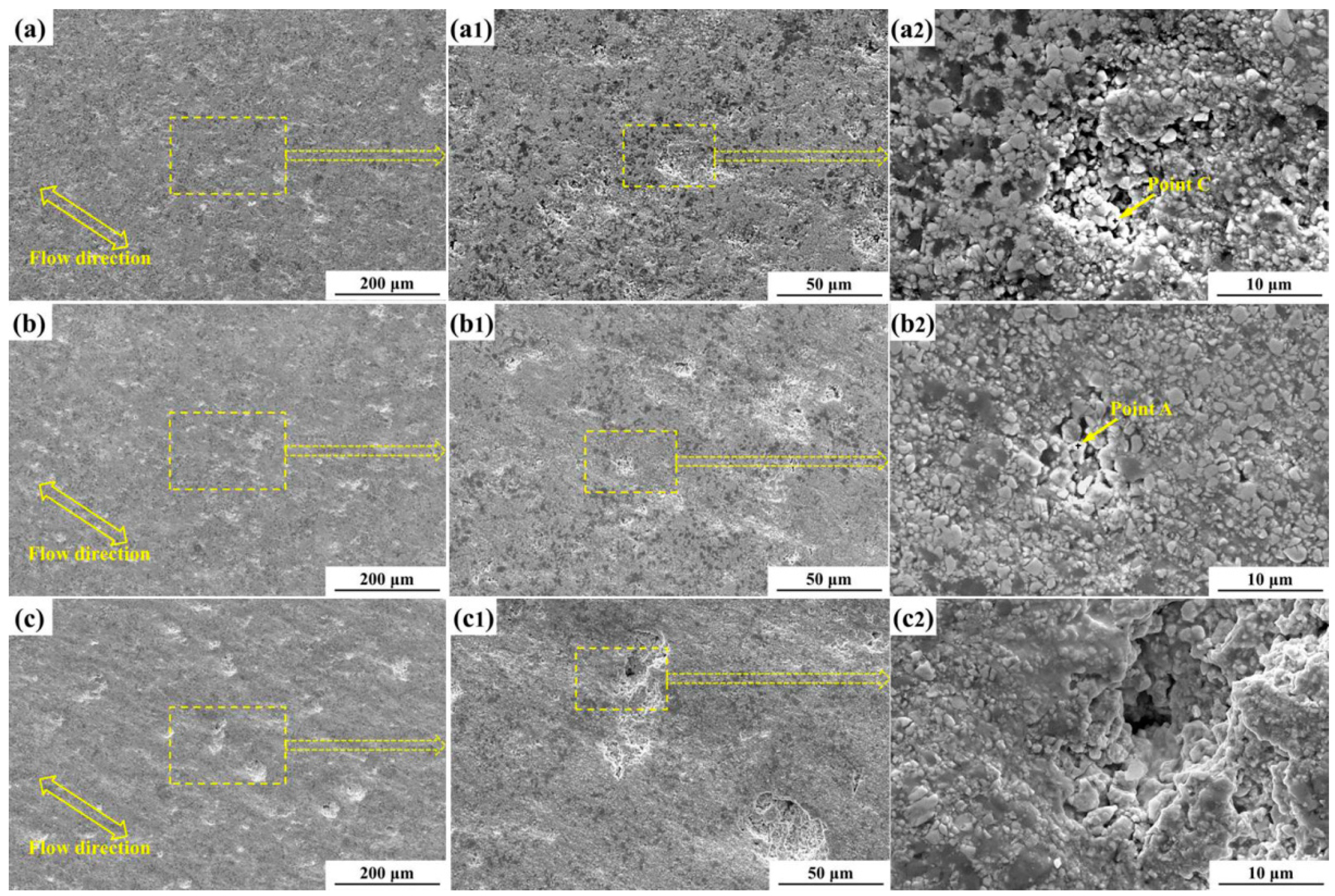
The predominant mechanisms causing the CSE degradation in 3.5 wt.% SCM of the WC-Cr3C2-Ni coating with the increase of the FV and SC were varying in terms of the discontinuous corrosion product films, the erosion pits, the fracturing of hard-phase grains, micro-cutting of soft binder matrix, and the crater formation, as well as coating spalling.

Author Contributions

Conceptualization, S.H.; methodology, W.S. and Z.Z.; investigation, Y.Z., M.K. and X.F.; data curation, J.L.; writing—original draft preparation, J.L.; writing—review and editing, S.H.; supervision, J.L. and S.H.; funding acquisition, J.L. and S.H. All authors have read and agreed to the published version of the manuscript.

Funding

This research was funded by the National Natural Science Foundation of China (grant nos. 52109091 and 51979083), the Fundamental Research Funds for the Central Universities (grant no. KYQN2022050), and the Natural Science Foundation of Jiangsu Province of China (grant no. BK20210409).

Institutional Review Board Statement

Not applicable.

Informed Consent Statement

Not applicable.

Data Availability Statement

The data presented in this study are available on request from the corresponding author.

Conflicts of Interest

The authors declare no conflict of interest.

References

  1. Singh, R.; Tiwari, S.K.; Mishra, S.K. Cavitation erosion in hydraulic turbine components and mitigation by coatings: Current status and future needs. J. Mater. Eng. Perform. 2011, 21, 1539–1551. [Google Scholar] [CrossRef]
  2. Wang, Y.; Wu, J.H.; Ma, F. Cavitation-silt erosion in sand suspensions. J. Mech. Sci. Technol. 2018, 32, 5697–5702. [Google Scholar] [CrossRef]
  3. Zhang, Y.Q.; Zang, W.; Zheng, J.H.; Cappietti, L.; Zhang, J.S.; Zheng, Y.; Fernandez-Rodriguez, E. The influence of waves propagating with the current on the wake of a tidal stream turbine. Appl. Energy 2021, 290, 116729. [Google Scholar] [CrossRef]
  4. Rameshk, M.; Soltanieh, M.; Masoudpanah, S.M. Effects of flow velocity and impact angle on erosion-corrosion of an API-5 L X65 steel coated by plasma nitriding of hard chromium underlayer. J. Mater. Res. Technol. 2020, 9, 10054–10061. [Google Scholar] [CrossRef]
  5. Padhy, M.K.; Saini, R.P. A review on silt erosion in hydro turbines. Renew. Sustain. Energy Rev. 2008, 12, 1974–1987. [Google Scholar] [CrossRef]
  6. Gohil, P.P.; Saini, R.P. Coalesced effect of cavitation and silt erosion in hydro turbines—A review. Renew. Sustain. Energy Rev. 2014, 33, 280–289. [Google Scholar] [CrossRef]
  7. Tang, X.; Zhang, S.; Cui, X.; Zhang, C.H.; Liu, Y.; Zhang, J.B. Tribological and cavitation erosion behaviors of nickel-based and iron-based coatings deposited on AISI 304 stainless steel by cold metal transfer. J. Mater. Res. Technol. 2020, 9, 6665–6681. [Google Scholar] [CrossRef]
  8. Fernández-Álvarez, M.; Velasco, F.; Bautista, A.; Abenojar, J. Effect of silica nanoparticles on the curing kinetics and erosion wear of an epoxy powder coating. J. Mater. Res. Technol. 2019, 9, 455–464. [Google Scholar] [CrossRef]
  9. Prashar, G.; Vasudev, H.; Thakur, L. Performance of different coating materials against slurry erosion failure in hydrodynamic turbines: A review. Eng. Fail. Anal. 2020, 115, 104622. [Google Scholar] [CrossRef]
  10. Singh, J.; Thakur, L.; Angra, S. Abrasive wear behavior of WC-10Co-4Cr cladding deposited by TIG welding process. Int. J. Refract. Met. Hard Mater. 2020, 88, 105198. [Google Scholar] [CrossRef]
  11. Kellner, F.J.J.; Hildebrand, H.; Virtanen, S. Effect of WC grain size on the corrosion behavior of WC-Co based hardmetals in alkaline solutions. Int. J. Refract. Met. Hard Mater. 2009, 27, 806–812. [Google Scholar] [CrossRef]
  12. Castberg, T.S.; Johnsen, R.; Berget, J. Erosion of hardmetals: Dependence of WC grain size and distribution, and binder composition. Wear 2013, 300, 1–7. [Google Scholar] [CrossRef]
  13. Li, G.P.; Peng, Y.B.; Yan, L.W.; Xu, T.; Long, J.Z.; Luo, F.H. Effects of Cr concentration on the microstructure and properties of WC-Ni cemented carbides. J. Mater. Res. Technol. 2020, 9, 902–907. [Google Scholar] [CrossRef]
  14. Ham, G.S.; Kreethi, R.; Kim, H.J.; Yoon, S.H.; Lee, K.H. Effects of different HVOF thermal sprayed cermet coatings on tensile and fatigue properties of AISI 1045 steel. J. Mater. Res. Technol. 2021, 15, 6647–6658. [Google Scholar] [CrossRef]
  15. Lin, J.R.; Hong, S.; Zheng, Y.; Sun, W.; Kang, M.; Fu, X.Q. Cavitation erosion resistance in NaCl medium of HVOF sprayed WC-based cermet coatings at various flow velocities: A comparative study on the effect of Ni and CoCr binder phases. Int. J. Refract. Met. Hard Mater. 2021, 94, 105407. [Google Scholar] [CrossRef]
  16. Souza, V.A.D.; Neville, A. Corrosion and synergy in a WC-Co-Cr HVOF thermal spray coating—Understanding their role in erosion-corrosion degradation. Wear 2005, 259, 171–180. [Google Scholar] [CrossRef]
  17. Magnani, M.; Suegama, P.H.; Espallargas, N.; Dosta, S.; Fugivara, C.S.; Guilemany, J.M.; Benedetti, A.V. Influence of HVOF parameters on the corrosion and wear resistance of WC-Co coatings sprayed on AA7050 T7. Surf. Coat. Technol. 2008, 202, 4746–4757. [Google Scholar] [CrossRef]
  18. Ribu, D.C.; Rajesh, R.; Thirumalaikumarasamy, D.; Kaladgi, A.R.; Saleel, C.A.; Nisar, K.S.; Shaik, S.; Afzal, A. Experimental investigation of erosion corrosion performance and slurry erosion mechanism of HVOF sprayed WC-10Co coatings using design of experiment approach. J. Mater. Res. Technol. 2022, 18, 293–314. [Google Scholar] [CrossRef]
  19. Hong, S.; Wu, Y.P.; Wu, J.H.; Zhang, Y.Q.; Zheng, Y.; Li, J.H.; Lin, J.R. Microstructure and cavitation erosion behavior of HVOF sprayed ceramic-metal composite coatings for application in hydro-turbines. Renew. Energy 2021, 164, 1089–1099. [Google Scholar] [CrossRef]
  20. Hong, S.; Mei, D.C.; Wu, J.H.; Lin, J.R.; Wu, Y.P.; Li, J.H.; Zheng, Y. Hydro-abrasive erosion and cavitation-silt erosion characteristics of HVOF sprayed WC-Ni cermet coatings under different flow velocities and sand concentrations. Ceram. Int. 2022. In Press. [Google Scholar] [CrossRef]
  21. Bolelli, G.; Berger, L.-M.; Bonetti, M.; Lusvarghi, L. Comparative study of the dry sliding wear behaviour of HVOF-sprayed WC-(W,Cr)2C-Ni and WC-CoCr hardmetal coatings. Wear 2014, 309, 96–111. [Google Scholar] [CrossRef]
  22. Bhosale, D.G.; Rathod, W.S. Investigation on wear behaviour of SS 316L, atmospheric plasma and high velocity oxy-fuel sprayed WC-Cr3C2-Ni coatings for fracturing tools. Surf. Coat. Technol. 2020, 390, 125679. [Google Scholar] [CrossRef]
  23. Bhosale, D.G.; Rathod, W.S. Tribological behaviour of atmospheric plasma and high velocity oxy-fuel sprayed WC-Cr3C2-Ni coatings at elevated temperatures. Ceram. Int. 2020, 46, 12373–12385. [Google Scholar] [CrossRef]
  24. Hou, G.L.; Zhou, H.D.; An, Y.L.; Liu, G.; Chen, J.M.; Chen, J. Microstructure and high-temperature friction and wear behavior of WC-(W,Cr)2C-Ni coating prepared by high velocity oxy-fuel spraying. Surf. Coat. Technol. 2011, 206, 82–94. [Google Scholar] [CrossRef]
  25. Hou, G.L.; An, Y.L.; Zhao, X.Q.; Chen, J.; Chen, J.M.; Zhou, H.D.; Liu, G. Effect of heat treatment on wear behaviour of WC-(W,Cr)2C-Ni coating. Surf. Eng. 2012, 28, 786–790. [Google Scholar] [CrossRef]
  26. Zhang, S.H.; Cho, T.Y.; Yoon, J.H.; Li, M.X.; Shum, P.W.; Kwon, S.C. Investigation on microstructure, surface properties and anti-wear performance of HVOF sprayed WC-CrC-Ni coatings modified by laser heat treatment. Mater. Sci. Eng. B 2009, 162, 127–134. [Google Scholar] [CrossRef]
  27. Thiruvikraman, C.; Balasubramanian, V.; Sridhar, K. Optimizing HVOF spray parameters to maximize bonding strength of WC-CrC-Ni coatings on AISI 304L stainless steel. J. Therm. Spray Technol. 2014, 23, 860–875. [Google Scholar] [CrossRef]
  28. Fang, W.; Cho, T.Y.; Yoon, J.H.; Song, K.O.; Hur, S.K.; Youn, S.J.; Chun, H.G. Processing optimization, surface properties and wear behavior of HVOF spraying WC-CrC-Ni coating. J. Mater. Process. Technol. 2009, 209, 3561–3567. [Google Scholar] [CrossRef]
  29. Berger, L.-M.; Saaro, S.; Naumann, T.; Wiener, M.; Weihnacht, V.; Thiele, S.; Suchánek, J. Microstructure and properties of HVOF-sprayed chromium alloyed WC-Co and WC-Ni coatings. Surf. Coat. Technol. 2008, 202, 4417–4421. [Google Scholar] [CrossRef]
  30. Qiao, L.; Wu, Y.P.; Hong, S.; Long, W.Y.; Cheng, J. Wet abrasive wear behavior of WC-based cermet coatings prepared by HVOF spraying. Ceram. Int. 2021, 47, 1829–1836. [Google Scholar] [CrossRef]
  31. Murariu, A.C.; Plesu, N.; Perianu, I.A.; Tara-Lunga-Mihali, M. Investigations on corrosion behaviour of WC-CrC-Ni coatings deposited by HVOF thermal spraying process. Int. J. Electrochem. Sci. 2017, 12, 1535–1549. [Google Scholar] [CrossRef]
  32. Wang, Q.; Zhang, Y.P.; Ding, X.; Wang, S.Y.; Ramachandran, C.S. Effect of WC grain size and abrasive type on the wear performance of HVOF-sprayed WC-20Cr3C2-7Ni coatings. Coatings 2020, 10, 660. [Google Scholar] [CrossRef]
  33. Berger, L.-M.; Saaro, S.; Naumann, T.; Kašparova, M.; Zahálka, F. Influence of feedstock powder characteristics and spray processes on microstructure and properties of WC-(W,Cr)2C-Ni hardmetal coatings. Surf. Coat. Technol. 2010, 205, 1080–1087. [Google Scholar] [CrossRef]
  34. Mayrhofer, E.; Janka, L.; Mayr, W.P.; Norpoth, J.; Ripoll, M.R.; Gröschl, M. Cracking resistance of Cr3C2-NiCr and WC-Cr3C2-Ni thermally sprayed coatings under tensile bending stress. Surf. Coat. Technol. 2015, 281, 169–175. [Google Scholar] [CrossRef]
  35. Hou, G.L.; Zhao, X.Q.; Zhou, H.D.; Lu, J.J.; An, Y.L.; Chen, J.M.; Yang, J. Cavitation erosion of several oxy-fuel sprayed coatings tested in deionized water and artificial seawater. Wear 2014, 311, 81–92. [Google Scholar] [CrossRef]
  36. Hong, S.; Wu, Y.P.; Wu, J.H.; Zheng, Y.; Zhang, Y.Q.; Cheng, J.B.; Li, J.H.; Lin, J.R. Effect of flow velocity on cavitation erosion behavior of HVOF sprayed WC-10Ni and WC-20Cr3C2-7Ni coatings. Int. J. Refract. Met. Hard Mater. 2020, 92, 105330. [Google Scholar] [CrossRef]
  37. Hong, S.; Lin, J.R.; Wu, Y.P.; Wu, J.H.; Zheng, Y.; Zhang, Y.Q.; Cheng, J.B.; Sun, W. Cavitation erosion characteristics at various flow velocities in NaCl medium of carbide-based cermet coatings prepared by HVOF spraying. Ceram. Int. 2021, 47, 1929–1939. [Google Scholar] [CrossRef]
  38. ASTM E2109-01; Standard Test Methods for Determining Area Percentage Porosity in Thermal Sprayed Coatings. ASTM International: West Conshohocken, PA, USA, 2021.
  39. Wang, Y.; Zheng, Y.G.; Wei, K.; Sun, W.H.; Hou, W.L.; Chang, X.C.; Wang, J.Q. Slurry erosion-corrosion behaviour of high-velocity oxy-fuel (HVOF) sprayed Fe-based amorphous metallic coatings for marine pump in sand-containing NaCl solutions. Corros. Sci. 2011, 53, 3177–3185. [Google Scholar] [CrossRef]
  40. Lu, X.X.; Shi, Y.B.; Wang, M. Prediction about seabed erosion/siltation near the water intake of third-phase project for Qinshan nuclear power plant. J. Sediment Res. 2000, 6, 10–15. (In Chinese) [Google Scholar] [CrossRef]
  41. Richards, B.T.; Zhao, H.B.; Wadley, H.N.G. Structure, composition, and defect control during plasma spray deposition of ytterbium silicate coatings. J. Mater. Sci. 2015, 50, 7939–7957. [Google Scholar] [CrossRef]
  42. Berger, L.-M.; Saaro, S.; Naumann, T.; Kašparova, M.; Zahálka, F. Microstructure and properties of HVOF-sprayed WC-(W,Cr)2C-Ni coatings. J. Therm. Spray Technol. 2008, 17, 395–403. [Google Scholar] [CrossRef]
  43. Bhosale, D.G.; Prabhu, T.R.; Rathod, W.S. Sliding and erosion wear behaviour of thermal sprayed WC-Cr3C2-Ni coatings. Surf. Coat. Technol. 2020, 400, 126192. [Google Scholar] [CrossRef]
  44. Celik, E.; Culha, O.; Uyulgan, B.; Ak Azem, N.F.; Ozdemir, I.; Turk, A. Assessment of microstructural and mechanical properties of HVOF sprayed WC-based cermet coatings for a roller cylinder. Surf. Coat. Technol. 2006, 200, 4320–4328. [Google Scholar] [CrossRef]
  45. Babu, P.S.; Basu, B.; Sundararajan, G. Processing-structure-property correlation and decarburization phenomenon in detonation sprayed WC-12Co coatings. Acta Mater. 2008, 56, 5012–5026. [Google Scholar] [CrossRef]
  46. Fu, W.; Chen, Q.Y.; Yang, C.; Yi, D.L.; Yao, H.L.; Wang, H.T.; Ji, G.C.; Wang, F. Microstructure and properties of high velocity oxygen fuel sprayed (WC-Co)-Ni coatings. Ceram. Int. 2020, 46, 14940–14948. [Google Scholar] [CrossRef]
  47. Kakaei, K.; Esrafili, M.D.; Ehsani, A. (Eds.) Graphene and Anticorrosive Properties. In Graphene Surfaces-Particles and Catalysts; Elsevier Science Publishing Company, Inc.: Amsterdam, The Netherlands, 2019; pp. 303–337. [Google Scholar]
  48. Mehdipour, M.; Afshar, A.; Mohebali, M. Electrophoretic deposition of bioactive glass coating on 316L stainless steel and electrochemical behavior study. Appl. Surf. Sci. 2012, 258, 9832–9839. [Google Scholar] [CrossRef]
  49. García, C.; Ceré, S.; Durán, A. Bioactive coatings prepared by sol-gel on stainless steel 316L. J. Non-Cryst. Solids 2004, 348, 218–224. [Google Scholar] [CrossRef]
  50. Li, Z.X.; Zhang, L.M.; Udoh, I.I.; Ma, A.L.; Zheng, Y.G. Deformation-induced martensite in 304 stainless steel during cavitation erosion: Effect on passive film stability and the interaction between cavitation erosion and corrosion. Tribol. Int. 2022, 167, 107422. [Google Scholar] [CrossRef]
  51. Zheng, Z.B.; Long, J.; Guo, Y.; Hui, L.; Zheng, K.H.; Qiao, Y.X. Corrosion and impact–abrasion–corrosion behaviors of quenching–tempering martensitic Fe–Cr alloy steels. J. Iron Steel Res. Int. 2022. [Google Scholar] [CrossRef]
  52. Bansal, A.; Singh, J.; Singh, H. Slurry erosion behavior of HVOF-sprayed WC-10Co-4Cr coated SS 316 steel with and without PTFE modification. J. Therm. Spray Technol. 2019, 28, 1448–1465. [Google Scholar] [CrossRef]
  53. Maekai, I.A.; Harmain, G.A.; Masoodi, J.H. Resistance to slurry erosion by WC-10Co-4Cr and Cr3C2-25(Ni20Cr) coatings deposited by HVOF stainless steel F6NM. Int. J. Refract. Met. Hard Mater. 2022, 105, 105830. [Google Scholar] [CrossRef]
  54. Dular, M.; Stoffel, B.; Sirok, B. Development of a cavitation erosion model. Wear 2006, 261, 642–655. [Google Scholar] [CrossRef]
  55. Aguirre, J.; Walczak, M.; Rohwerder, M. The mechanism of erosion-corrosion of API X65 steel under turbulent slurry flow: Effect of nominal flow velocity and oxygen content. Wear 2019, 438–439, 203053. [Google Scholar] [CrossRef]
  56. Liu, X.B.; Kang, J.J.; Yue, W.; Fu, Z.Q.; Zhu, L.N.; She, D.S.; Liang, J.; Wang, C.B. Performance evaluation of HVOF sprayed WC-10Co4Cr coatings under slurry erosion. Surf. Eng. 2018, 35, 816–825. [Google Scholar] [CrossRef]
  57. Li, S.C. Cavitation enhancement of silt erosion—An envisaged micro model. Wear 2006, 260, 1145–1150. [Google Scholar] [CrossRef]
  58. Sun, J.; Ge, X.F.; Chu, D.D.; Zhang, L.; Meng, H.; Zheng, Y. Effects of sediment diameter and concentration on cavitation characteristics and mechanism. Tribol. Int. 2022, 171, 107543. [Google Scholar] [CrossRef]
  59. Wheeler, D.W.; Wood, R.J.K. Erosion damage in diamond coatings by high velocity sand impacts. Philos. Mag. 2007, 87, 5719–5740. [Google Scholar] [CrossRef]
  60. Katsumata, T.; Matsubara, Y.; Yamamoto, K.; Iwai, Y. Evaluation of coating properties with a Micro Slurry-jet Erosion (MSE) test: Effects of the shape and size of erodent particles on erosion behaviors of TiN coating. Surf. Coat. Technol. 2021, 421, 127443. [Google Scholar] [CrossRef]
  61. Sapate, S.G.; Tangselwar, N.; Paul, S.N.; Rathod, R.C.; Mehar, S.; Gowtam, D.S.; Roy, M. Effect of coating thickness on the slurry erosion resistance of HVOF-sprayed WC-10Co-4Cr coatings. J. Therm. Spray Technol. 2021, 30, 1365–1379. [Google Scholar] [CrossRef]
  62. Su, K.P.; Wu, J.H.; Xia, D.K. Classification of regimes determining ultrasonic cavitation erosion in solid particle suspensions. Ultrason. Sonochem. 2020, 68, 105214. [Google Scholar] [CrossRef]
Figure 1. FE-SEM micrographs of the feedstock powder: (a) typical surface morphology; (b) a magnification of the rectangular frame in (a).
Jmse 10 01341 g001
Figure 2. Schematic diagram of the test apparatus (a), the rotating disk compartment for the CSE test (b), and the corresponding specimen size (c).
Jmse 10 01341 g002
Figure 3. FE-SEM micrographs and EDS analysis of the as-sprayed coating: (ad) typical cross-sectional microstructures, (e) EDS result of Point A, (f) EDS result of Point B.
Jmse 10 01341 g003
Figure 4. XRD patterns of the feedstock powder and the as-sprayed coating [37].
Jmse 10 01341 g004
Figure 5. Nanomechanical properties of the WC-Cr3C2-Ni coating and the 1Cr18Ni9Ti stainless steel.
Jmse 10 01341 g005
Figure 6. Potentiodynamic polarization curves of the WC-Cr3C2-Ni coating and the 1Cr18Ni9Ti stainless steel in 3.5 wt.% SCM.
Jmse 10 01341 g006
Figure 7. Volume loss rates of the WC-Cr3C2-Ni coating and the 1Cr18Ni9Ti stainless steel after CSE for 6 h in 3.5 wt.% SCM at 20 kg·m−3 and different FVs.
Jmse 10 01341 g007
Figure 8. Volume loss rates of the WC-Cr3C2-Ni coating and the 1Cr18Ni9Ti stainless steel after CSE for 6 h in 3.5 wt.% SCM at 33.5 m·s−1 and different SCs.
Jmse 10 01341 g008
Figure 9. FE-SEM images of the WC-Cr3C2-Ni coatings after CSE for 6 h in 3.5 wt.% SCM at 20 kg·m−3 and different FVs: (a) 23.4 m·s−1, (b) 33.5 m·s−1, (c) 41.9 m·s−1.
Jmse 10 01341 g009
Figure 10. FE-SEM images of the WC-Cr3C2-Ni coatings after CSE for 6 h in 3.5 wt.% SCM at 33.5 m·s−1 and different SCs: (a) 10 kg·m−3, (b) 20 kg·m−3, (c) 35 kg·m−3.
Jmse 10 01341 g010
Table 1. Operating parameters of the CSE tests in 3.5 wt.% SCM.
Operating ParametersFlow Velocity (m·s−1)
23.433.541.9
Sand concentration (kg·m−3)10
20
35
Table 2. Composition of elements in different regions of WC-Cr3C2-Ni coating after CSE for 6 h in 3.5 wt.% SCM under different FVs and SCs.
RegionElement (at.%)
OCrCWNi
A11.84.965.616.61.1
B5.711.663.711.87.2
C16.76.556.217.53.1
Publisher’s Note: MDPI stays neutral with regard to jurisdictional claims in published maps and institutional affiliations.

