Article

Development and Optimization of an Offset Spiral Tooth Fertilizer Discharge Device

1
College of Biological and Agricultural Engineering, Jilin University, Changchun 130022, China
2
Key Laboratory of Key Technology on Agricultural Machine and Equipment, Ministry of Education, South China Agricultural University, Guangzhou 510642, China
3
Maoming Branch, Guangdong Laboratory for Modern Agriculture, Maoming 525000, China
4
Huangpu Innovation Research Institute, South China Agricultural University, Guangzhou 510725, China
*
Author to whom correspondence should be addressed.
Agriculture 2024, 14(2), 329; https://doi.org/10.3390/agriculture14020329
Submission received: 14 January 2024 / Revised: 14 February 2024 / Accepted: 17 February 2024 / Published: 19 February 2024
(This article belongs to the Special Issue Agricultural Machinery Design and Agricultural Engineering)

Abstract

:
Due to factors such as a small amount of fertilizer application during rice topdressing and slow machine speed, the ordinary fertilizer discharge device fails to distribute the fertilizer uniformly and accurately as required, making it difficult to meet the needs of precise rice topdressing. This research focuses on the development of an offset spiral tooth fertilizer discharge device suitable for rice topdressing. The study analyzes the amount of fertilizer discharged in one cycle, the fertilizer force, and the motion of the fertilizer particles. In order to enhance the uniformity of the fertilizer discharge device at a low speed and small volume, the discrete element method is employed to conduct experimental research on the key structural parameters that affect the one-cycle amount of discharged fertilizer and the dynamics of the fertilizer discharge device. Through single-factor tests, it was found that the angle, height, number of spiral teeth, and diameter of the fertilizer discharge wheel are closely associated with the fertilizer discharge performance. To further investigate the impact of these four parameters on the fertilizer discharge performance, a regression combination test of the four factors is conducted based on the range optimized by the single-factor tests. A multi-objective mathematical model, considering the key parameters of fertilizer uniformity coefficient, one-cycle amount of fertilizer, and fertilizer discharge torque, is established at three speeds: 20, 55, and 90 rpm. The response surface method is utilized to analyze the influence of the interaction factors on the fertilizer discharge performance. The optimal combination of the key structural parameters was determined as follows: spiral tooth angle of 35.42°, tooth height of 9.02 mm, discharge wheel diameter of 57.43 mm, and tooth amount of 9.37. The bench test results of the device, using the optimal parameter combination and a fertilizer discharge speed of 0–90 rpm, were obtained for four commonly used rice fertilizers. The maximum variation coefficient of fertilizer discharge was found to be 10.42%. The one-cycle amount of fertilizer discharge was measured to be 19.82 ± 0.72 (A Kang), 17.20 ± 0.69 (Ba Tian), 20.34 ± 0.54 (Yaran), and 14.51 ± 0.44 (granular urea). The fertilizer discharge torque remained stable. These results indicate that the achieved optimization meets the precise fertilizer application requirements and can provide technical support for precise topdressing operations.

1. Introduction

Rice, a crucial food crop, is primarily cultivated in Asia, accounting for 89.4% of the global rice production [1]. It plays a vital role in ensuring food security [2]. Fertilizer application is an essential practice for enhancing rice quality and yield [3]. Specifically, applying fertilizers during the tillering stage of rice offers several benefits, such as increasing the number of effective tillering, improving grain quality, reducing cadmium accumulation [4,5], enhancing the protein content, minimizing chalkiness and chalky rice occurrence [6], and reducing greenhouse gas emissions, like methane [7]. Additionally, it helps to achieve higher fertilizer utilization rates [8,9,10]. Numerous agricultural researchers have highlighted the positive effects of rice tillering fertilizer, and the practice of dividing fertilizer into multiple applications has been widely promoted in southern China [11,12]. However, the lack of suitable fertilizer application equipment hinders accurate fertilization standards, limiting the achievement of precise fertilization.
As a crucial element in precision fertilization, the fertilizer distributor plays a vital role in accurately delivering the required amount of fertilizer. The groove wheel fertilizer distributor is widely accepted due to its simple structure and convenient control [13]. For rice basal fertilization, Chen, H.B. et al. designed an air-blowing spiral groove fertilizer distributor [14]. This design optimized the accuracy and uniformity of the fertilizer distributor’s output and investigated the impact of the rotation speed of the fertilizer distributor wheel and the effective length of the groove wheel on the variation coefficient of the fertilizer distributor. Sun, J. et al. utilized a discrete element method and 3D-printing technology to optimize the spiral angle parameter and groove wheel depth of the spiral groove wheel [15]. Similarly, Jinsong Liu et al. focused on enhancing the uniformity of fertilizer distribution by designing a fertilizer diversion plate and optimizing its structural parameters using DEM methold [16]. Additionally, Song XF et al. employed the cohesive model in the discrete element method to conduct simulation regression experiments [17]. Their objective was to optimize the spiral groove structure parameters to address the issue of blockage in the groove wheel fertilizer distributor caused by moisture absorption and the agglomeration of fertilizers.
The current method of applying topdressing to rice using unmanned aerial vehicles does not meet the agronomic requirements for lateral depth topdressing as suggested by previous studies. Chen et al. discovered that applying fertilizer at a depth of 80–120 mm between rows of rice during the tillering stage can enhance its absorption by the rice roots [12]. This not only improves the fertilizer utilization rate but also enhances the quality of rice. However, the amount of fertilizer applied during rice topdressing is typically only about 30% of the basal fertilizer [3]. Moreover, the slow operating speed of rice field machinery poses challenges when using a common groove wheel fertilizer distributor for topdressing. This restricts the fertilizer distributor to work at low rotation speeds and with small groove wheel lengths, leading to difficulties in achieving precise fertilization. This working state has been widely reported to result in an uneven fertilizer flow [15,18]. Therefore, it is evident that a common groove wheel fertilizer distributor is unsuitable for small topdressing operations and cannot fulfill the requirements of rice topdressing.
To address the aforementioned issues, this study developed an offset spiral tooth fertilizer discharge device with a motor drive. The discrete element method was employed to analyze the inherent relationship between the four key parameters of the spiral tooth angle, height, number, and diameter of the fertilizer distributor wheel, and the resulting one-cycle amount of fertilizer and variation coefficient. Single-factor tests were conducted to analyze the individual effects of each parameter and determine their respective ranges of influence. Moreover, regression tests were carried out to analyze the interaction effects between these parameters using the response surface method. A multivariate regression model, considering high, medium, and low speeds, was established to incorporate multiple factors and indicators. Subsequently, a multi-objective parameter optimization was performed to obtain the optimal process parameters. The results of the bench test demonstrate that the proposed fertilizer distributor achieves a variation coefficient that meets operational requirements at low work speeds. This design fulfills the precise delivery requirements of late-stage rice fertilization and provides valuable equipment selection guidance for accurate rice topdressing.

2. Working Principles and Parameter Analysis

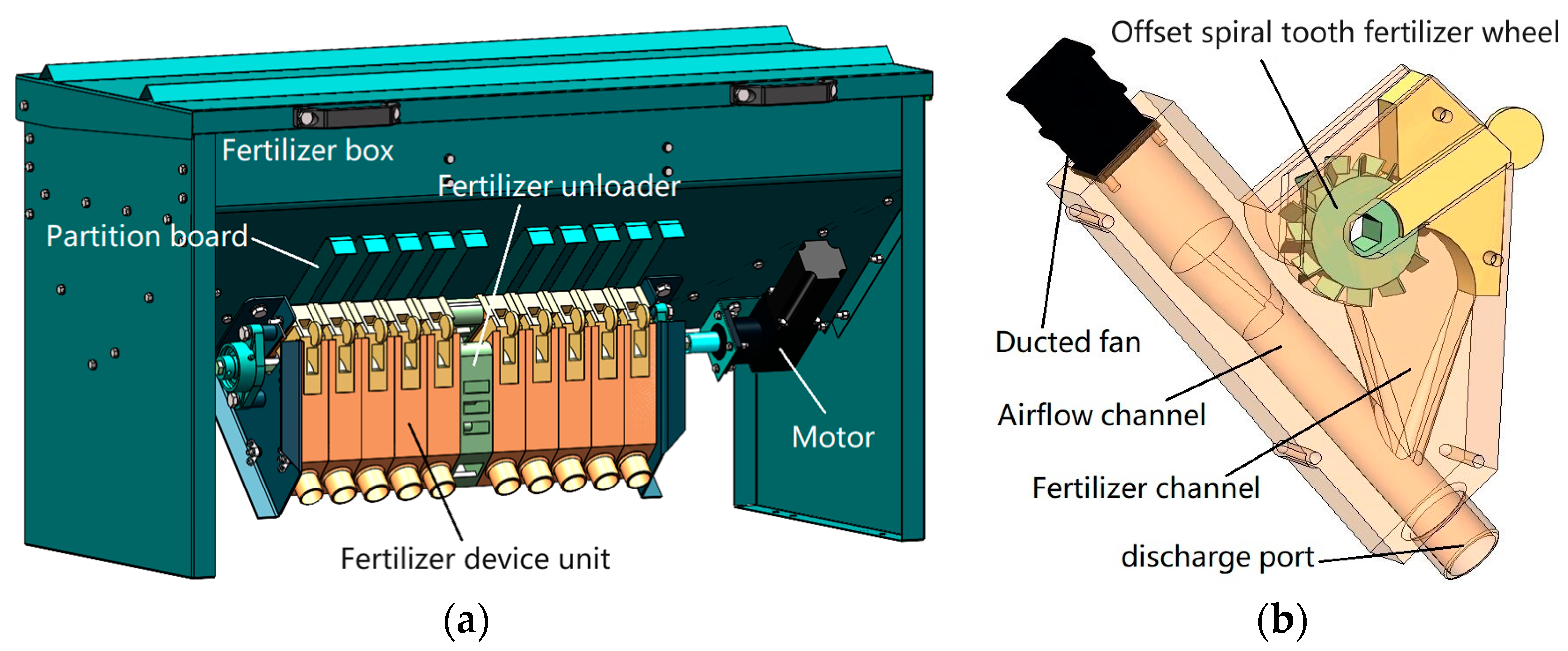
2.1. Structure and Working Principles

The rice topdressing and fertilizer distribution device is illustrated in Figure 1. In Figure 1a, the overall structure of the equipment is depicted, comprising a fertilizer box, a drive motor, a residual fertilizer unloader, and 10 fertilizer device units. The structure of the fertilizer device unit is shown in Figure 1b, consisting of a ducted fan, an offset spiral tooth fertilizer wheel, and a shell.
According to rice-planting agronomy principles, the fertilizer distributor is designed to perform single-row topdressing. Each fertilizer device unit corresponds to a rice row and is centrally installed. Each unit is equipped with an offset spiral tooth fertilizer wheel and a hexagonal shaft passing through the center of the fertilizer wheel. One end of the hexagonal shaft is connected to the drive motor. The fertilizer in the fertilizer box fills the tooth groove on the fertilizer wheel. When the motor is started, the fertilizer wheel rotates uniformly and orderly under the action of the hexagonal shaft, resulting in the even discharge of the fertilizer. A ducted fan is used to quickly deliver the fertilizer to the space between the rice rows. By adjusting the rotation speed of the fertilizer wheel, the amount of fertilizer can be changed to achieve precise topdressing for a single rice row.
The designed fertilizer device belongs to the groove wheel fertilizer device. The conveying part of the groove wheel fertilizer device is divided into a forced layer and a driven layer. The conveying amount of the forced layer depends on the outer contour characteristics of the groove wheel, while the conveying amount of the driven layer is uncertain [19]. In this study, the fertilizer device that was designed did not have a driven layer. The gap between the outer side of the fertilizer wheel and the shell of the fertilizer device unit was 0.5 mm, which is smaller than the particle size of the fertilizer. Due to the lack of buffering in the driven layer, there is a possibility that the fertilizer particles in the closed gap between the fertilizer wheel and the shell are sheared or squeezed, resulting in instability in the torque of the fertilizer device. The offset teeth of the device provide a space for these fertilizer particles to escape. Therefore, the fertilizer output of the groove wheel-type fertilizer distributor was calculated by Equation (1) [20], and the effective working length of the fertilizer wheel was one-third of the ordinary groove wheel. The length of the offset spiral tooth fertilizer wheel was L = 25 mm.
q = L A z γ α 0 ,
where γ represents the material density (g/cm3), α0 is the material filling coefficient, A represents the cross-sectional area of a single groove (cm2), and z represents the number of teeth on the fertilizer wheel.

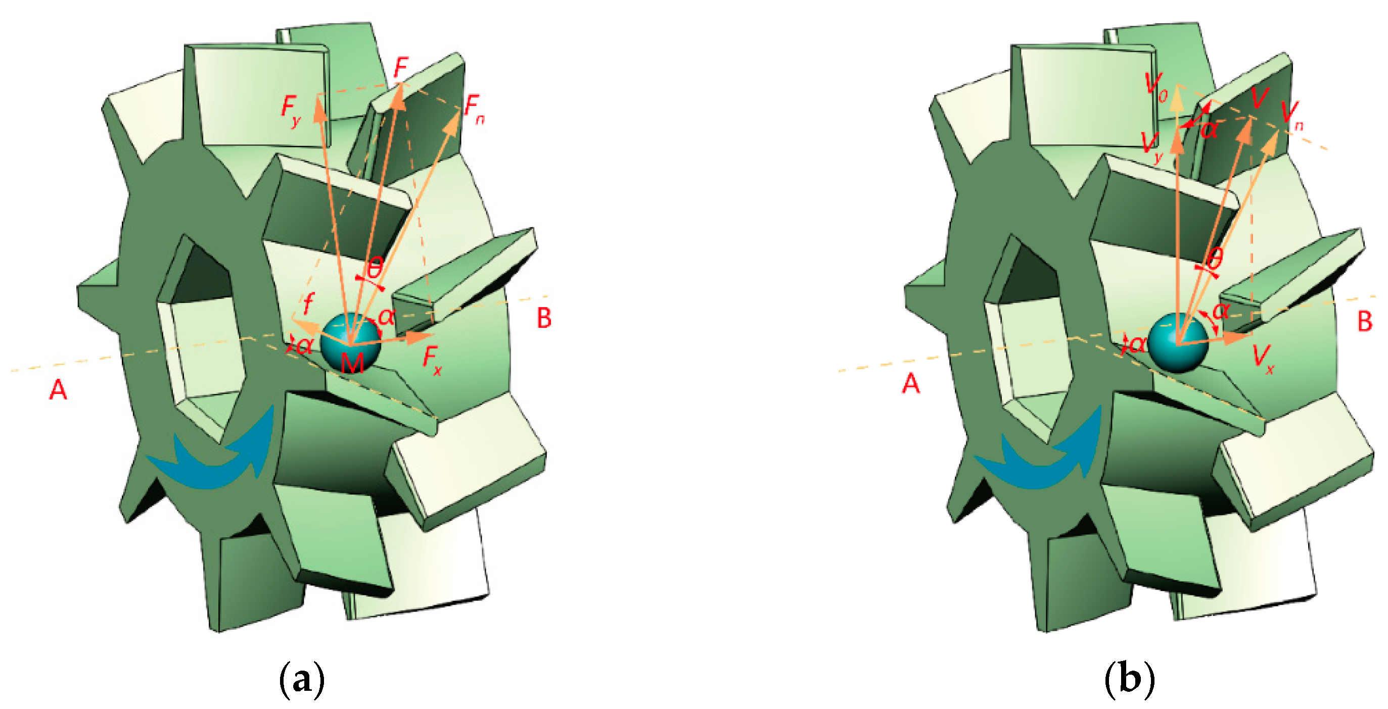
2.2. Kinematic Analysis of the Fertilizer Particles

Fertilizer particles exhibit radial movement as influenced by the fertilizer wheel and shell. Additionally, due to the spiral-inclined surface of the tooth surface, there is a possibility for the fertilizer particles to move axially along the spiral axis. Figure 2a illustrates the force analysis of the fertilizer particle M at r from the fertilizer wheel axis AB. The inclination angle of the fertilizer teeth is represented by α, and the tooth surface exerts a supporting force Fn on the particles, which is perpendicular to the tooth surface. The frictional force between the particles and the tooth surface is denoted as f. The resultant force F, formed by Fn and f, creates an angle θ with Fn. Consequently, the particles experience both radial and axial movement due to the respective components of the force F, namely Fy and Fx [21]. The axial and radial forces acting on the particles are provided in Equations (2) and (3).
F x = F cos ( α + θ ) ,
F y = F sin ( α + θ ) ,
Assuming the fertilizer wheel rotates at an angular velocity of ω and the initial velocity of the fertilizer is 0, the tangential velocity of the fertilizer particle M at a distance r from the rotational axis AB is V0. This velocity is directed along the tangent to the rotational motion at point M. Neglecting the effect of friction results in a resultant velocity Vn that is perpendicular to the blade surface. However, due to the friction between the particles and the spiral tooth surface, the direction of the resultant velocity V undergoes an angular deviation of θ, known as the friction angle. The final resultant velocity V is illustrated in Figure 2b. The axial and radial components of the resultant velocity V are decomposed into Vx and Vy (circular velocity), respectively. The axial velocity and radial motion can be represented by Equation (4) and Equation (5), respectively.
V y = tan ( α + θ ) × ω D 120 × f + 1 r 1 + 2 π R tan ( α + θ ) + r 2 ,
V x = tan ( α + θ ) × ω D 120 × 1 f r 1 + 2 π R tan ( α + θ ) + r 2 ,
where f represents the coefficient of friction between the fertilizer particles and the tooth surface of the fertilizer wheel.
In summary, the performance of the offset spiral tooth fertilizer device is mainly affected by 4 structural parameters: the number of teeth on the fertilizer wheel (z), the groove area (A), the helix angle of the fertilizer teeth (θ), and the rotational speed (ω). The groove area (A) is influenced by the diameter of the fertilizer wheel (D) and the height of the tooth (h). When the tooth thickness is disregarded, the groove area (A) can be calculated using the formula (2Dhh2)π/4z. Therefore, the objective of this study is to conduct experiments to investigate the impact of the number of teeth on the fertilizer wheel (z), the height of the fertilizer tooth (h), the outer diameter of the fertilizer wheel (D), the helix angle of the fertilizer teeth (θ), and the rotational speed (ω).

3. Simulation Analysis

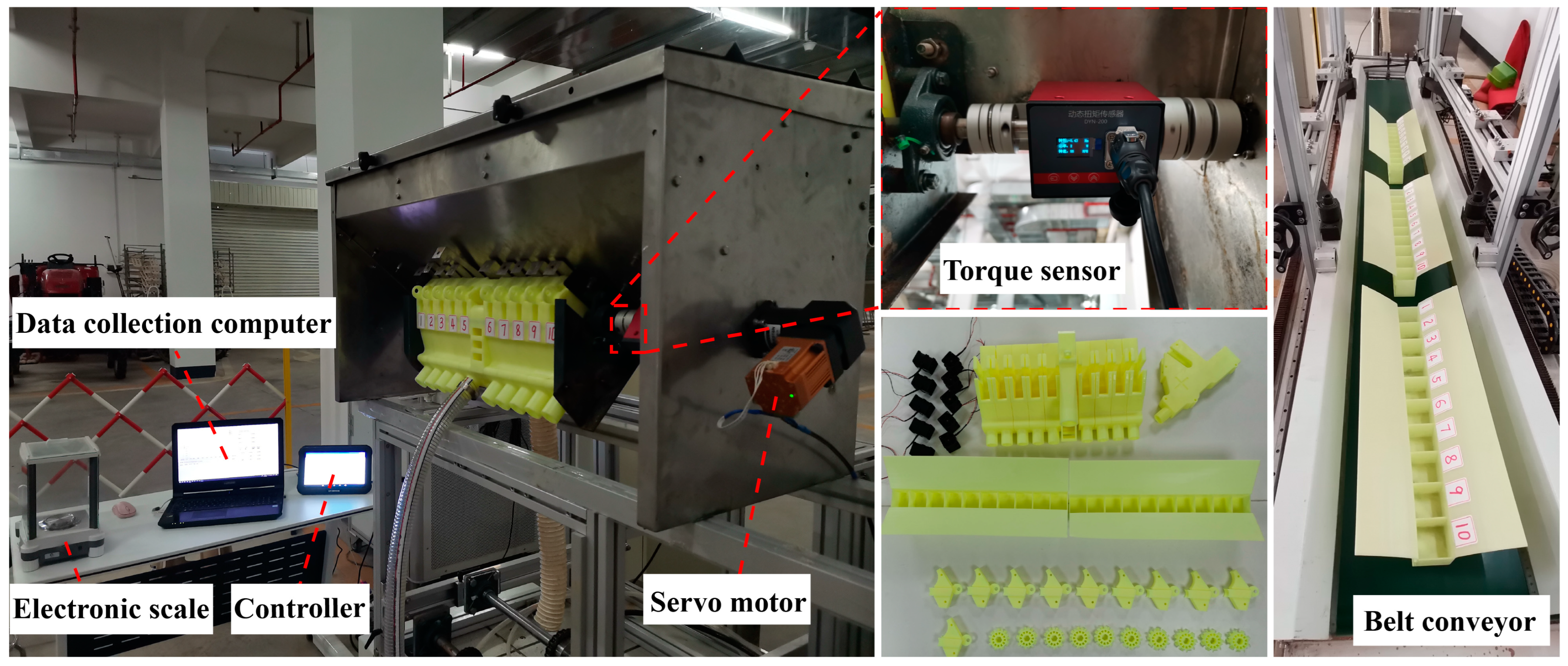
3.1. Simulation Details

The discrete element method (DEM) is a numerical computational method proposed by Cundall P A et al. that is used to study the motion and mechanical characteristics of complex discrete systems [22]. It is considered a mature and well-established theoretical and methodological approach [23]. To clarify the material parameters of fertilizers used for rice topdressing, four commonly used fertilizers in southern China were measured using a grading sieve, an angle of repose measuring instrument, and an emptying method [17]. The density and angle of repose of the four fertilizers are shown in Figure 3a, and the probability distribution density of the particle size is shown in Figure 3b, both of which exhibit a Gaussian distribution. This indicates that there are significant differences between the four fertilizers and that they are generally representative. The four fertilizers are A Kang complex fertilizer (Beijing Yongshengfeng Agricultural Materials Co., Ltd., Beijing, China), Ba Tian (Shenzhen Batian Ecological Engineering Co., Ltd., Shenzhen, China), Yaran compound fertilizer (Norwegian Yaran International Co., Ltd., Hong Kong, China), and granular urea (Hubei Sanning Chemical Industry Co., Ltd., Yichang, China).
In this study, the fertilizer discharge process was assumed to be an ideal water-free environment with no bonding between particles. The Hertz–Mindlin (no slip) contact model was used to describe the interaction between the fertilizer particles and the geometric body of the discharge device [24]. The contact mechanics parameters between the fertilizer particles and the PLA plastic material of the discharge device were determined based on the relevant literature and the experimental methods [25,26,27], as shown in Table 1.
The simulation of the angle of repose of the fertilizer particles was conducted using EDEM 2020 software, as depicted in Figure 4e. The parameters used for the simulation are provided in Table 1. The obtained angle of repose was found to be 27.28°, which closely aligns with the angles of repose measured for the four fertilizers shown in Figure 4a–d. This suggests that the parameters utilized in the discrete element model accurately represent the fertilizers and enable the simulation of the fertilizer particle behavior.

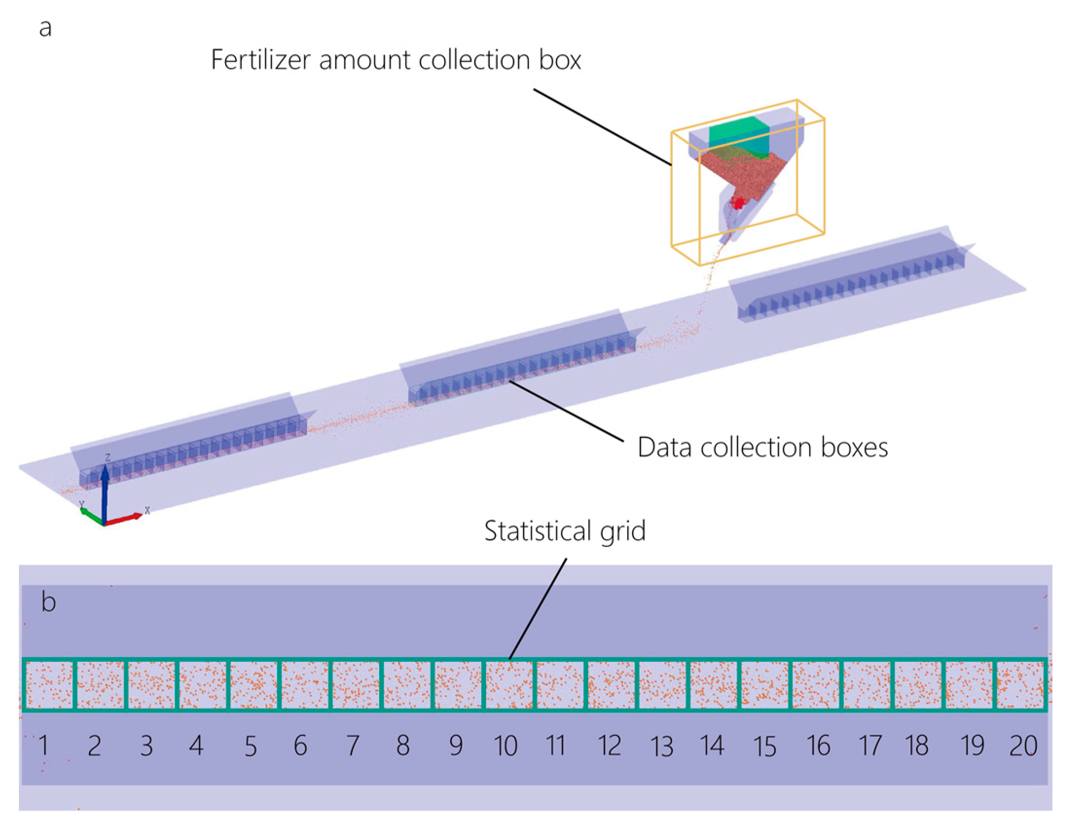
3.2. Evaluation Criteria and Data Collection Methods

The one-cycle amount of fertilizer is a crucial parameter for measuring the performance of a discharge device and serves as the primary basis for assessing its adaptability [20,28]. A larger discharge amount indicates that the device can meet the demand for larger fertilization amounts, while a smaller amount suggests otherwise. This study focuses on developing discharge devices with smaller one-cycle amounts of fertilizer. The variation coefficient of discharge is an evaluation index used to measure the uniformity of discharge. A smaller variation coefficient signifies a more uniform fertilization process and reduces the likelihood of breaking fertilizer strips and gathering fertilizer together [16,29]. Furthermore, considering that the fertilizer discharge device designed in this paper does not have a driving layer, the fertilizer located at the edge of the fertilizer wheel teeth when the wheel filling is completed collides with the fertilizer discharge device shell and brake. This collision causes the fertilizer discharge torque to be unstable. Therefore, the experiment selected a one-cycle amount of fertilizer, variation coefficient of discharge, and discharge torque as indicators to evaluate the design quality. The specific data collection and processing methods are as follows.

3.2.1. One-Cycle Amount of Fertilizer

In the test, the fertilizer box was filled to a minimum of two-thirds of its volume before initiating the discharge process. To collect the fertilizer, a fertilizer amount collection box, consisting of the fertilizer box and discharge device, was placed at the discharge port, as shown in Figure 5a. The one-cycle amount of fertilizer was determined using Equation (6).
Q S = 60 n × q 1 q 2 t 2 t 1 ,
where Qs represents the one-cycle amount of fertilizer (g/cycle); n represents the rotational speed of the discharge wheel (rpm); and q1 and q2 represent the total mass of fertilizer in the box at times t1 and t2, respectively.

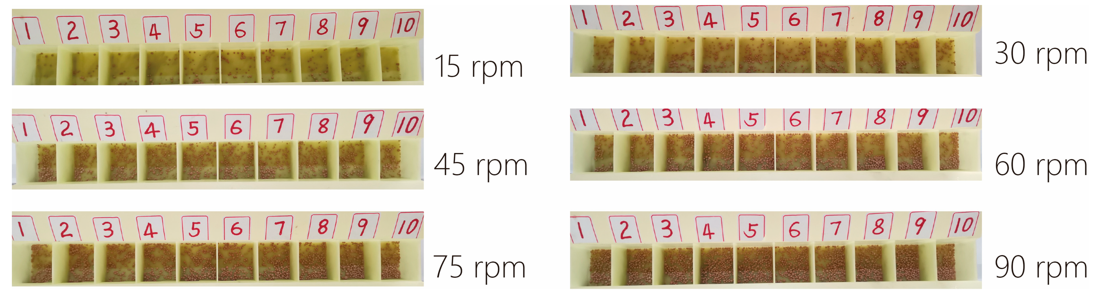
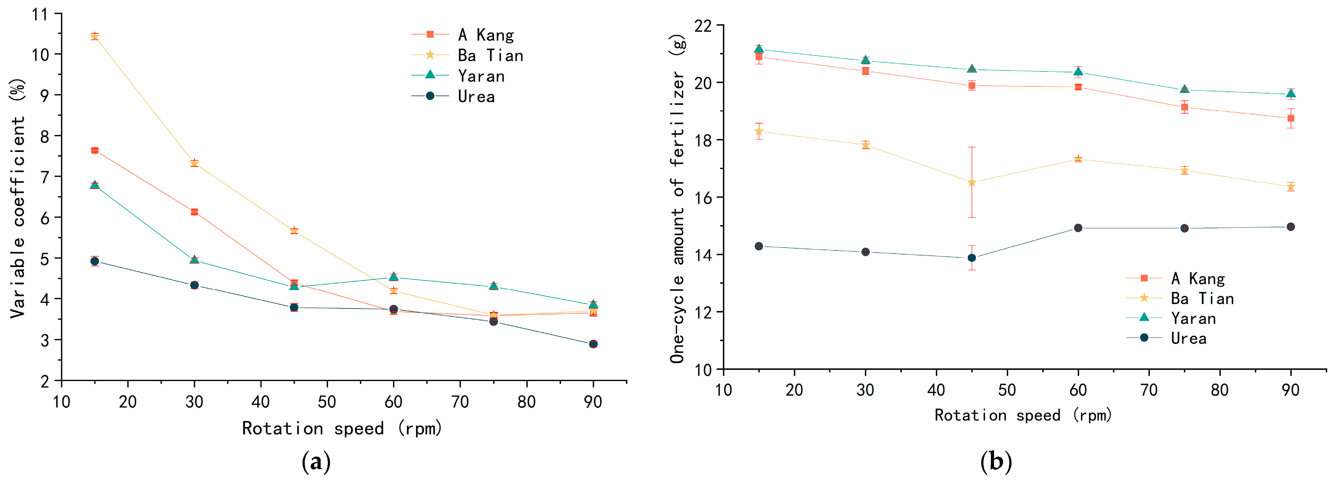
3.2.2. Uniformity of Discharge

In accordance with the relevant studies [25,30,31], three sets of data collection boxes, each containing 20 small cubes measuring 50 mm × 50 mm × 50 mm, were positioned beneath the simulation fertilizer device, as shown in Figure 5b. Once the fertilizer was discharged steadily from the device, the fertilizer device unit was controlled to move along the x-axis at a speed of 0.6 m/s, and the fertilizer was dropped into the data collection box. After the simulation, the quality of the fertilizer in each of the 20 grids was counted individually. The average fertilizer quality, standard deviation, and variation coefficient for the fertilizer uniformity in each statistical grid unit within the fertilizer performance test group were calculated using Equations (7)–(9).
m ¯ = i = 1 20 m i n ( i = 1 , 2 , , 20 ) ,
s = i = 1 20 ( m i m ¯ ) 2 n 1 ( i = 1 , 2 , , 20 ) ,
σ = s m ¯ × 100 % ,
where mi represents the total mass of fertilizer particles in the i-th grid (g); n represents the number of statistical grid units; m ¯ represents the average mass of fertilizer particles in the statistical grid unit (g); s represents the standard deviation between the statistical grid units in a single experiment (g); and σ represents the variation coefficient of the fertilizer uniformity between the statistical grid units in a single test (%).

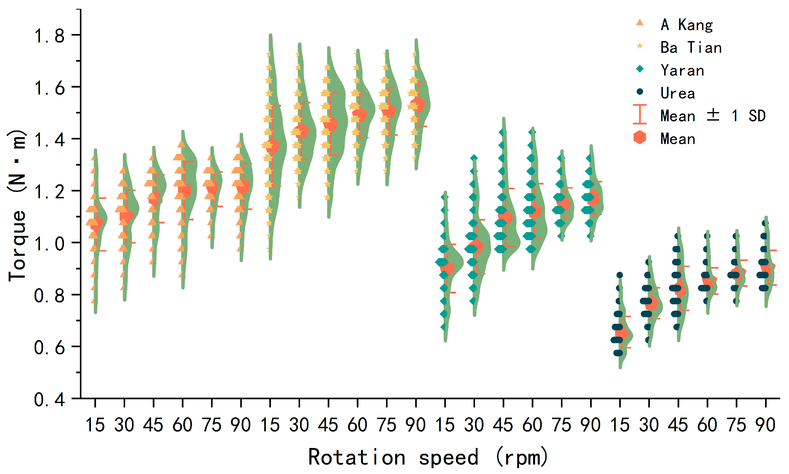
3.2.3. Fertilizer Discharge Torque

The fertilizer discharge device studied in this paper did not have a driven layer of fertilizer; so, the chance of the existence of extrusion and shearing of particles at the closure of the discharge wheel and the shell is higher than that of the fertilizer discharger with a driven layer, and this damage to the fertilizer causes the instability of the fertilizer discharge torque [32]. Therefore, the torque was chosen as one of the evaluation criteria in this paper.
Due to the instability of dynamic torque data, a combined analysis approach is commonly employed for processing its torque load spectrum. This involves methods such as frequency spectrum transformation and rain flow counting [33,34]. However, it is important to note that the discrete element simulation overlooks the mechanical interaction and assembly errors in mechanical structures, which can lead to idealized results. In this study, 500 torque values were obtained within 5 s after stable discharge. These values were then used to create a half-violin plot using the Origin 2021 software. This plot provided insights into the distribution, mean value, and standard deviation of the torque, allowing for a visual representation of torque changes.

4. Single-Factor Test and Result Analysis

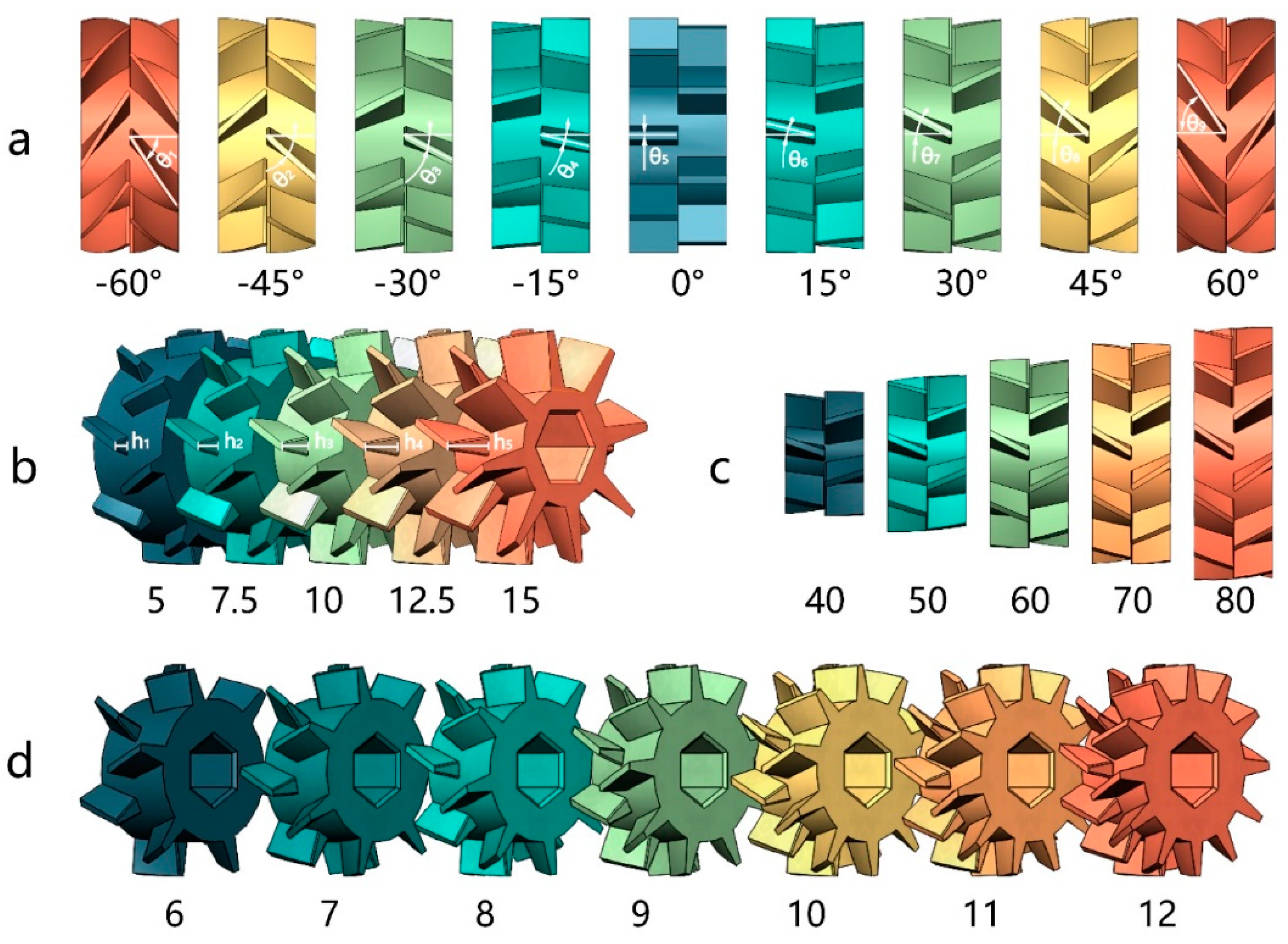
4.1. Single-Factor Test Design

To investigate the impact of four factors-angle, height, number, and diameter of the offset spiral teeth fertilizer discharge wheel-on the discharge performance of the discharge device, single-factor simulation tests were conducted. These tests adhered to the principle of varying only one variable at a time. For the angle factor, nine tests were conducted with the teeth angles ranging from −60° to 60°, as depicted in Figure 6a. The height of the tooth was fixed at 10 mm, the discharge wheel diameter at 60 mm, and the number of discharge teeth at 10. When examining the height of the spiral teeth, the setup was as shown in Figure 6b, with an angle of 30°, a diameter of 60 mm, 10 discharge teeth, and heights of 5 mm, 7.5 mm, 10 mm, 12.5 mm, and 15 mm. Similarly, for the discharge wheel diameter, the five diameters of 40 mm, 50 mm, 60 mm, 70 mm, and 80 mm were employed, as shown in Figure 6c, with an angle of 30°, a height of 10 mm, and 10 discharge teeth. Lastly, when investigating the number of discharge teeth, seven different numbers of teeth were tested, as illustrated in Figure 6d, with an angle of 30°, a height of 10 mm, and a diameter of 60 mm.

4.2. Single-Factor Test Results and Analysis

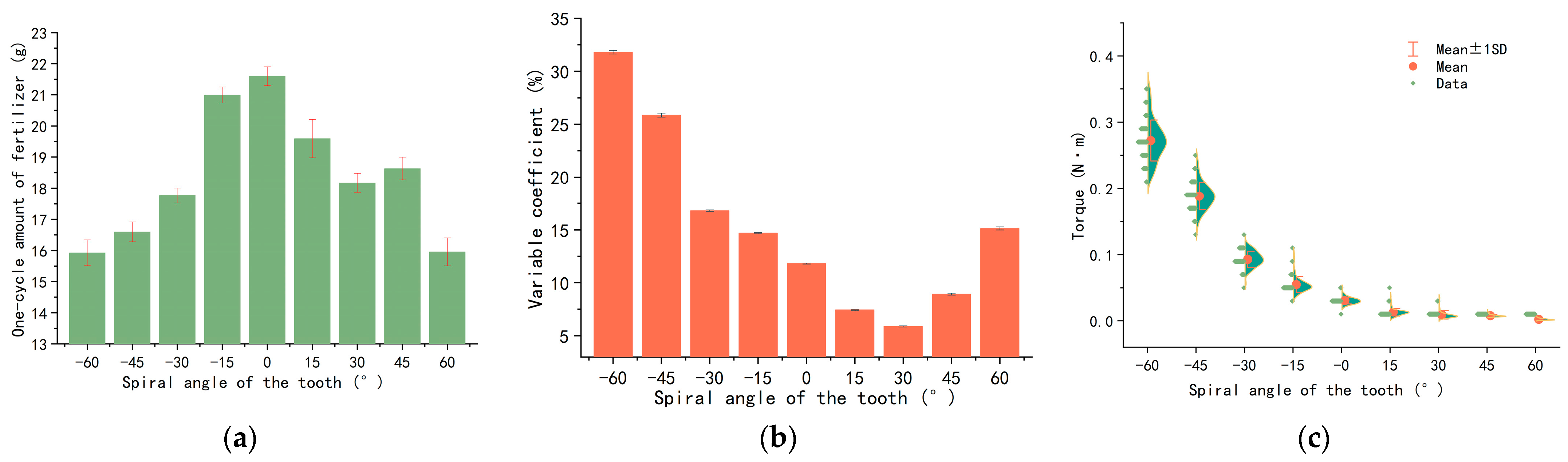
4.2.1. Influence of the Spiral Angle of the Tooth

Figure 7 illustrates the significant impact of the offset spiral teeth angle of the fertilization wheel on various factors, such as the one-cycle amount of fertilizer, and the variation coefficient. Figure 7a demonstrates that the one-cycle amount of fertilizer initially increases with the angle, reaches its peak near 0 degrees, and then decreases. However, within the range of 15–45 degrees, the one-cycle amount of fertilizer changes at a slower rate. Figure 7b indicates that the uniformity of fertilization gradually declines as the angle increases, reaching its lowest point around 30 degrees, and then gradually improving. Additionally, the variation coefficient exhibits an increasing trend with the angle. Figure 7c shows that the fertilizer torque decreases as the angle changes from −60° to 60°, but the rate of decrease slows down after 15°.

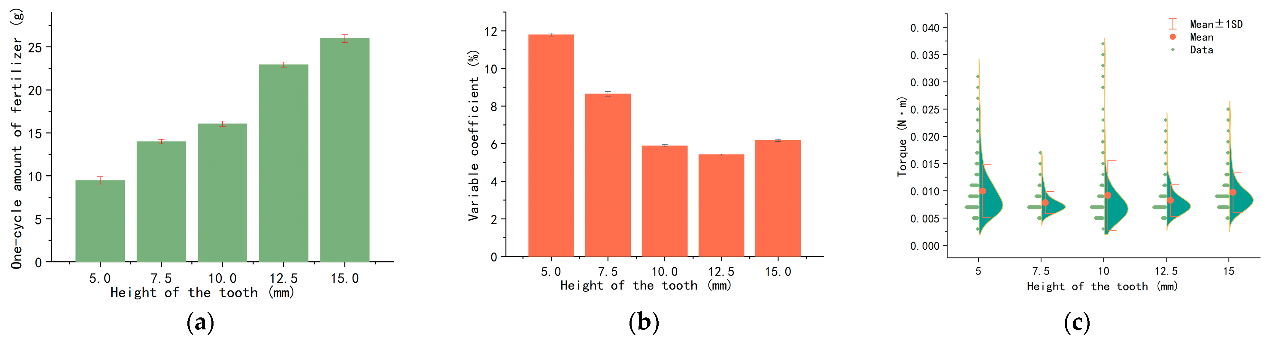
4.2.2. Influence of the Height of the Tooth

Figure 8a illustrates that as the height of the tooth of the fertilizer discharge wheel increases, the one-cycle amount of fertilizer also increases. Additionally, Figure 8b demonstrates that the variation coefficient of the fertilizer output decreases rapidly with the increase in the height of the tooth, and then increases slightly after the height of the tooth reaches 12.5 mm. Figure 8c analyzes the fertilizer torque at various heights of the tooth, revealing that the torque is minimally affected by the height and exhibits a relatively concentrated mean value. However, the maximum torque value is irregularly distributed.

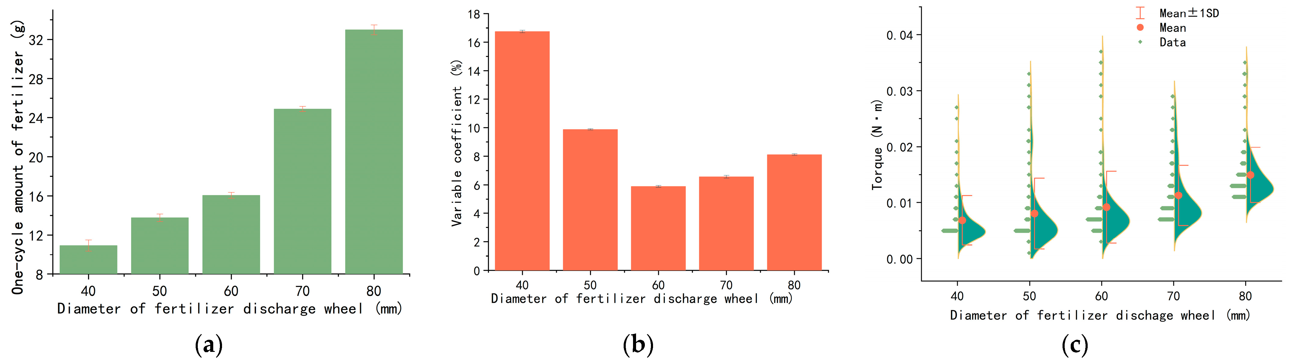
4.2.3. Influence of the Diameter of the Fertilizer Discharge Wheel

The impact of the diameter of the fertilizer wheel on the one-cycle amount of fertilizer is illustrated in Figure 9a. It is observed that, as the diameter of the fertilizer discharge wheel increases, the one-cycle amount of fertilizer also increases. Figure 9b presents the results indicating that the variation coefficient of the fertilizer output initially decreases and then increases with the increase in the diameter of the fertilizer wheel. The minimum value of the variation coefficient is observed near a diameter of 60 mm. The change rate of the variation coefficient is relatively slow before and after this minimum value. The fertilizer torque is depicted in Figure 9c, and it is observed that the mean value of the torque increases with the diameter.

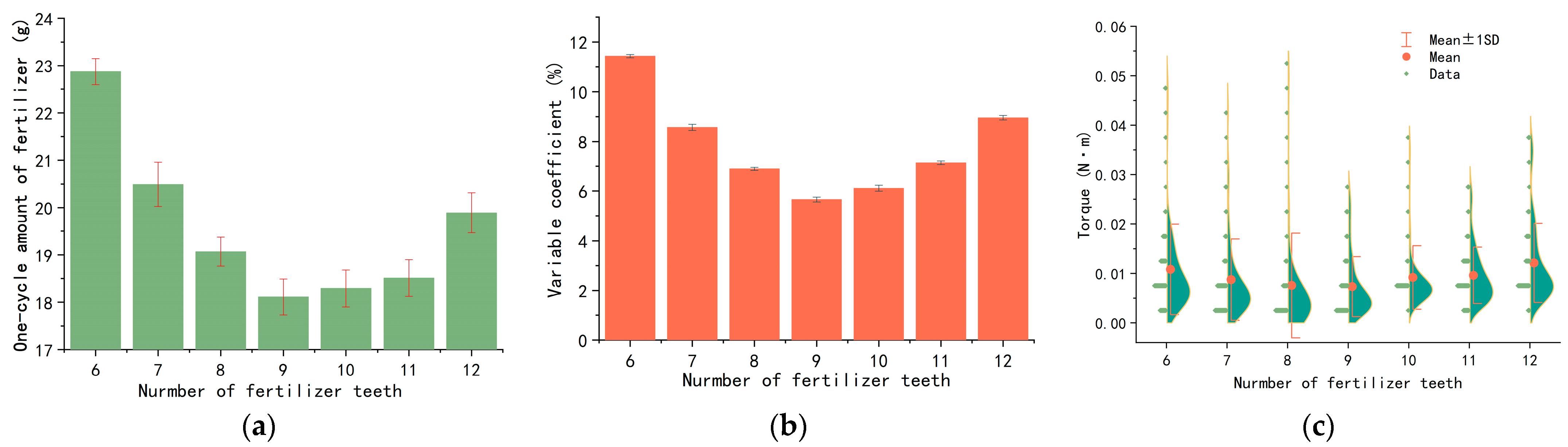
4.2.4. Influence of the Number of Teeth of the Fertilizer Discharge Wheel

According to Figure 10a,b, it can be observed that, as the number of teeth of the fertilizer discharge wheel increases, both the one-cycle amount of fertilizer and the variation coefficient of the fertilizer output exhibit a pattern of initially decreasing and then increasing. The minimum values for both parameters are obtained when the number of teeth is nine. On the other hand, the mean value of the fertilizer torque, as depicted in Figure 10c, shows relatively less variation with respect to the number of teeth.

5. Parameter Regression Test and Optimization

5.1. Regression Test Design

The single-factor test revealed a close relationship among the angle, height, number, and diameter of the offset spiral teeth of the fertilizer wheel and the one-cycle amount of fertilizer, the variation coefficient of the fertilizer output, and the fertilizer torque. To further optimize the performance of these four structural parameters at different operating rotation speeds, a comprehensive assessment of the fertilizer device was conducted at three speeds (20 rpm, 55 rpm, and 90 rpm). A 4-factor 2-level regression combination test was designed.
The test factors and level coding were carried out following Equation (10), and xj2 was centered using Equation (11). The coding results are presented in Table 2, where z1, z2, z3, and z4 represent the offset spiral teeth angle, height, diameter, and number of offset spiral teeth in natural space, respectively. Similarly, x1, x2, x3, and x4 represent the offset spiral teeth angle, height, outer diameter, and number of offset spiral teeth in coding space, respectively.
x j = 2 × ( z j z 0 j ) z 2 j z 1 j ,
x ij = x ij 2 1 N i = 1 N x ij 2 ,
The test was conducted based on the arrangement described in Table 3.

5.2. Regression Model and Significance Test Analysis

The test results were analyzed using a regression model variance analysis, regression coefficient significance test, and lack-of-fit test. Table 4 shows that the p-values of the quadratic regression models for the variation coefficient of fertilizer output, one-cycle amount of fertilizer, and fertilizer torque, established by the influencing factors, were all less than 0.05, indicating their significance. The p-values of the lack-of-fit test were all greater than 0.05, suggesting a high degree of fit and no lack-of-fit phenomenon in the regression equations. Therefore, the nine regression models obtained from the test are effective, and the parameters of the fertilizer applicator can be optimized based on these models.
The p-values obtained from the coefficient significance test were used to evaluate the impact of the parameters on the regression model. A p-value lower than 0.01 indicates that the parameter has a significant impact on the model, while a p-value greater than 0.05 indicates that the parameter has no significant impact on the model. When the discharge wheel was set at a rotation speed of 20 rpm, seven parameters (x2, x3, x1x2, x12, x22, x32, and x42) had an extremely significant impact on the variation coefficient CV(20 rpm) model (p < 0.01). Additionally, two parameters (x1 and x4) had a significant impact on the variation coefficient CV (20 rpm) model (p < 0.05). For the one-cycle amount of fertilizer Q(20 rpm) model, five parameters (x2, x3, x4, x2x3, and x42) had an extremely significant impact (p < 0.01), while parameters x1x3 and x12 had a significant impact (p < 0.05). In terms of the fertilizer torque T(20 rpm), two parameters (x1 and x3) had an extremely significant impact (p < 0.01), and three parameters (x2, x12, and x42) had a significant impact (p < 0.05). When the discharge wheel was set at a rotation speed of 55 rpm, six parameters (x2, x3, x1x2, x12, x22, and x42) had an extremely significant impact on the variation coefficient CV(55 rpm) with a p-value lower than 0.01. Additionally, two parameters (x1 and x1x3) had a significant impact on the variation coefficient CV(55 rpm) with a p-value lower than 0.05. Furthermore, six parameters (x2, x3, x4, x1x3, x2x3, and x22) had an extremely significant impact on the one-cycle amount of fertilizer model Q(55 rpm) with a p-value lower than 0.01. Two parameters (x1 and x3) had an extremely significant impact on the fertilizer torque model T(55 rpm) with a p-value lower than 0.01.When the discharge wheel was set at a rotation speed of 90 rpm, three parameters (x2, x3, and x42) had an extremely significant impact on the variation coefficient CV(90 rpm) model (p < 0.01). Two parameters (x12 and x22) had a significant impact on the variation coefficient CV(90 rpm) model (p < 0.05). Six parameters (x2, x3, x4, x1x3, x2x3, and x22) had an extremely significant impact on the one-cycle amount of fertilizer Q(90 rpm) model (p < 0.01). Two parameters (x1 and x3) had an extremely significant impact on the fertilizer torque T(90 rpm) model (p < 0.01).
The regression model for the variation coefficient of the fertilizer output and the one-cycle amount of fertilizer at different rotation speeds in natural space were calculated using Equation (11), as shown in Equation (12). The model was optimized.
C V ( 20 rpm ) = 141.54 + 0.33 x 1 0.85 x 2 2.4 x 3 12.44 x 4 0.043 x 1 x 2 + 0.0086 x 1 2 + 0.11 x 2 2 + 0.017 x 3 2 + 0.48 x 4 2 Q ( 20 rpm ) = 84.53 0.94 x 1 0.68 x 2 1.33 x 3 6.82 x 4 + 0.011 x 1 x 3 + 0.057 x 2 x 3 + 0.0048 x 1 2 + 0.37 x 4 2 T ( 20 rpm ) = 0.104 0.001 x 1 0.0006 x 2 0.0017 x 3 0.0078 x 4 + 0.0000085 x 1 2 + 0.00046 x 4 2 C V ( 55 rpm ) = 78.68 + 0.47 x 1 0.57 x 2 0.86 x 3 10.42 x 4 0.035 x 1 x 2 0.0091 x 1 x 3 + 0.007 x 1 2 + 0.094 x 2 2 + 0.54 x 4 2 Q ( 55 rpm ) = 57.68 0.73 x 1 0.12 x 2 x 3 4.11 x 4 + 0.011 x 1 x 3 + 0.062 x 2 x 3 0.053 x 2 2 T ( 55 rpm ) = 0.032 0.0006 x 1 + 0.002 x 2 + 0.00059 x 3 + 0.0036 x 4 C V ( 90 rpm ) = 50.27 + 0.88 x 1 0.74 x 2 0.6 x 3 6.41 x 4 + 0.0037 x 1 2 + 0.04 x 2 2 + 0.26 x 4 2 Q ( 90 rpm ) = 7 0.53 x 1 + 0.46 x 2 0.27 x 3 0.54 x 4 + 0.01 x 1 x 3 + 0.059 x 2 x 3 0.079 x 2 2 T ( 90 rpm ) = 0.054 0.00027 x 1 + 0.0015 x 2 0.0019 x 3 + 0.00021 x 4

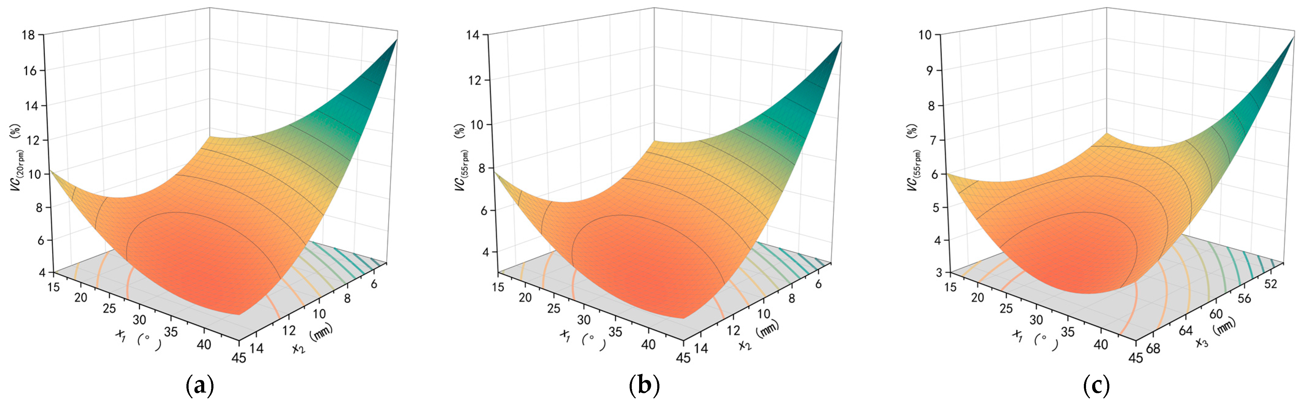
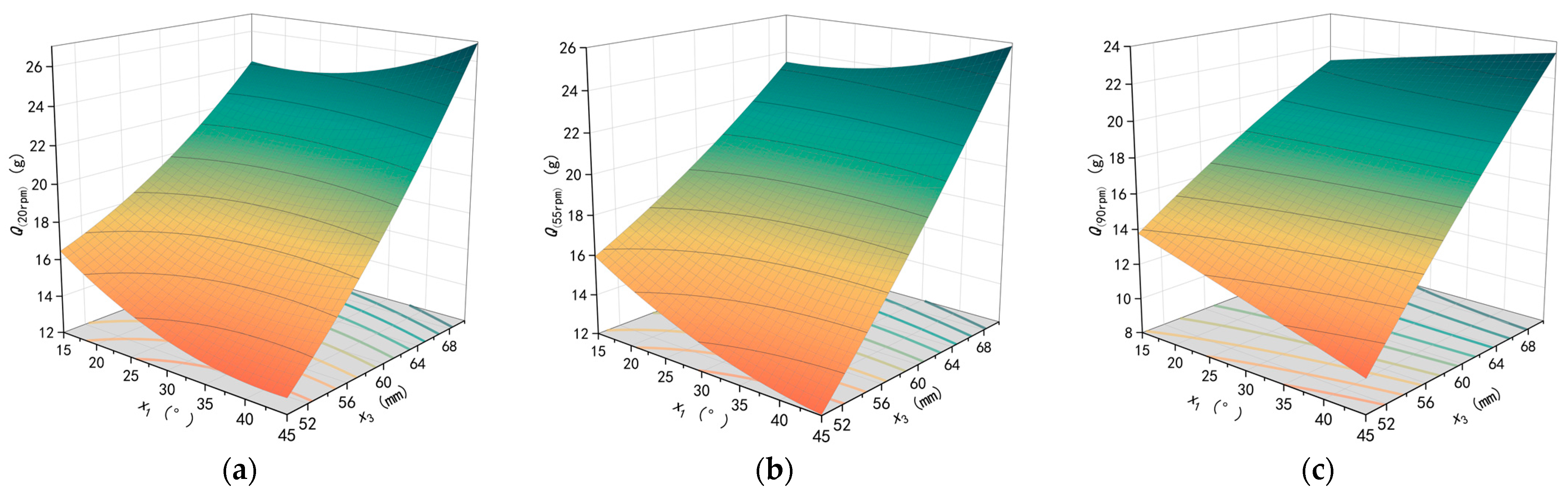
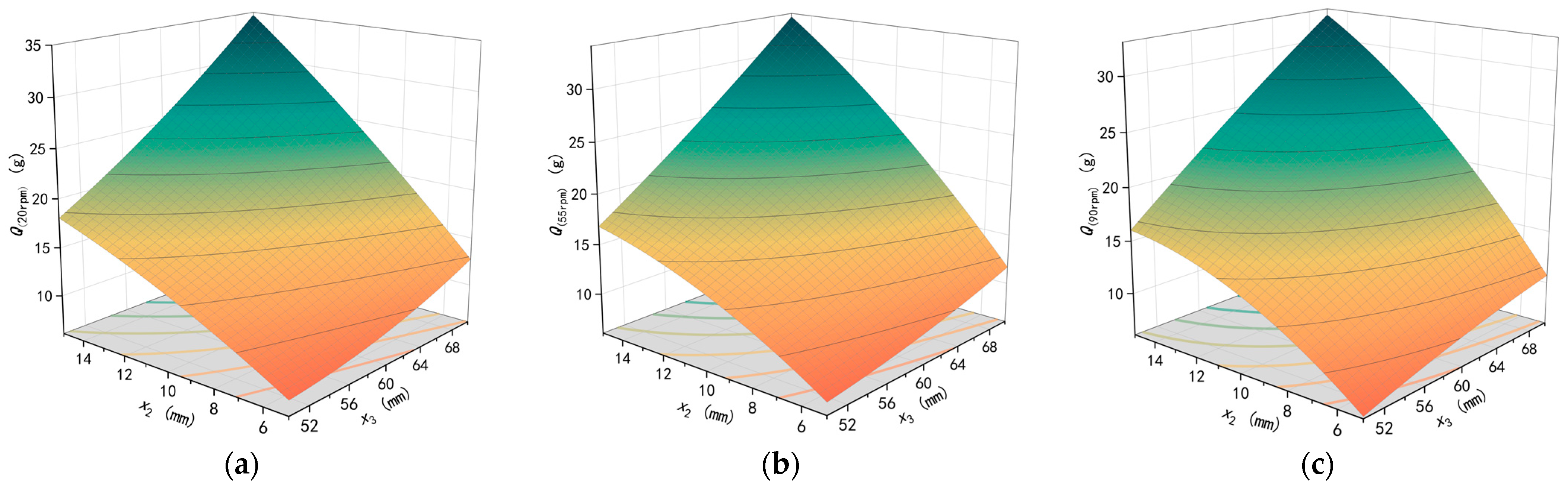
5.3. Analysis of the Interactive Factors

According to the analysis, the test results are influenced by interaction factors. When the rotation speed is 20 rpm, the interaction x1x2 has an extremely significant impact on the variation coefficient VC (20 rpm). The interaction effects x1x3 and x2x3 have significant and extremely significant impacts on the one-cycle amount of fertilizer Q (20 rpm), respectively. At a rotation speed of 55 rpm, the interaction effects x1x2 and x1x3 have extremely significant and significant impacts on VC(55 rpm), respectively. Similarly, the interaction effects x1x3 and x2x3 have extremely significant impacts on Q(55 rpm). At a rotation speed of 90 rpm, the interaction effects x1x3 and x2x3 have very significant impacts on Q(90 rpm). The response surfaces of these interaction effects were obtained using the design-expert 8.0.6 software and are shown in Figure 11, Figure 12, Figure 13, Figure 14 and Figure 15.
Figure 11a,b illustrate the impact of the interaction between the spiral angle and height of the tooth on the variation coefficient. The rotation speeds of 20 rpm and 55 rpm were considered, while keeping the diameter of the fertilizer wheel (x3) at 60 mm and the number of fertilizer teeth (x4) at nine. It is observed that the variation coefficient of the fertilizer output is minimized when the spiral angle of the tooth is large and the height of the tooth is high. Conversely, the variation coefficient increases as the spiral angle of the tooth decreases and the height of the tooth increases. The variation coefficient of the fertilizer output also increases rapidly with the increase in the spiral angle of the teeth and the decrease in the height of the tooth. Furthermore, Figure 11c demonstrates the effect of the interaction between the spiral angle of the tooth (x1) and the diameter of the fertilizer wheel (x3) on the variation coefficient at a rotation speed of 55 rpm. In this case, the height of the fertilizer tooth (x2) is fixed at 10 mm and the number of fertilizer teeth (x4) is nine. It is observed that the variation coefficient VC(55 rpm) initially decreases and then increases with the increase in the spiral angle of the tooth. Moreover, when the spiral angle of the tooth is large, the variation coefficient decreases with the increase in the diameter of the fertilizer wheel.
Figure 12 examines the interaction effect of x1x3, which represents the spiral angle of the tooth (x1) and the diameter of the fertilizer wheel (x3), on the one-cycle amount of fertilizer. The height of the tooth (x2) is fixed at 10 mm, and the number of fertilizer teeth (x4) is set at nine. In Figure 12a, at a rotation speed of 20 rpm, the one-cycle amount of fertilizer increases as the diameter of the fertilizer wheel increases. When the diameter of the fertilizer wheel is small, the one-cycle amount of fertilizer decreases with an increased spiral angle of the tooth. However, when the diameter of the fertilizer wheel is large, the one-cycle amount of fertilizer increases with an increased spiral angle of the teeth. The trend of this interaction effect remains consistent at the rotation speeds of 55 rpm and 90 rpm, as shown in Figure 12b and Figure 12c, respectively.
When the spiral angle of the teeth is 30° (x1) and the number of teeth is nine (x4), the interaction effect between the height of the teeth (x2) and the diameter of the fertilizer wheel (x3) on the one-cycle amount of fertilizer is shown in Figure 13. The effect trend of this interaction on the one-cycle amount of fertilizer remains consistent at the rotation speeds of 20 rpm, 55 rpm, and 90 rpm. The one-cycle amount of fertilizer increases with the increase in both the diameter of the fertilizer wheel and the height of the fertilizer tooth. However, when the diameter of the fertilizer wheel is small, the increase in the one-cycle amount of fertilizer with the increase in the height of the fertilizer tooth is slower compared to when the diameter of the fertilizer wheel is large.

6. Parameter Optimization and Verification Test

6.1. Parameter Optimization

To determine the most effective parameters for the fertilizer device, this study utilized the optimization module of the Design-Expert 8.0.6 software. The objective was to minimize the variation coefficient and torque while maintaining a consistent one-cycle amount of fertilizer of approximately 18 g–20 g. The optimization conditions are shown in Equation (13).
15 ° x 1 45 ° 7.5   mm x 2 12.5 mm 55   mm x 3 65 mm 8 x 4 12 min 5 C V ( 20 rpm ) ( x 1 , x 2 , x 3 , x 4 ) 7.5 min 18 Q ( 20 rpm ) ( x 1 , x 2 , x 3 , x 4 ) 20 min T ( 20 rpm ) ( x 1 , x 2 , x 3 , x 4 ) min 3 C V ( 55 rpm ) ( x 1 , x 2 , x 3 , x 4 ) 5 min 18 Q ( 55 rpm ) ( x 1 , x 2 , x 3 , x 4 ) 20 min T ( 55 rpm ) ( x 1 , x 2 , x 3 , x 4 ) min 2 C V ( 90 rpm ) ( x 1 , x 2 , x 3 , x 4 ) 3 min 18 Q ( 90 rpm ) ( x 1 , x 2 , x 3 , x 4 ) 20 min T ( 90 rpm ) ( x 1 , x 2 , x 3 , x 4 )
The optimization results indicate that the fertilizer device performs optimally with the combination of the following parameters: a spiral angle of teeth angle of 35.42°, a fertilizer teeth height of 9.02 mm, a diameter of the fertilizer wheel of 57.43 mm, and the number of the tooth of nine. These parameters consistently yield the best results across all three speeds.

6.2. Verification Test

To verify the fertilization performance of the optimized results, 3D-printing technology was utilized to manufacture the fertilizer device. The device was then installed on a test platform equipped with a belt conveyor. The platform is depicted in Figure 14. Ten offset spiral tooth fertilizer devices with centrally installed and driven by servo motors were used. A sensor capable of collecting the real-time fertilization torque was installed between the fertilizer device and the motor. The same variation coefficient acquisition box, with specifications identical to those of the simulation test, was placed on a 6 m long belt conveyor. The belt conveyor was adjusted by the controller to operate at a speed of 0.6 m/s, and the test was conducted at different rotation speeds: 15 rpm, 30 rpm, 45 rpm, 60 rpm, 75 rpm, and 90 rpm. The calculations of the fertilization variation coefficient and the one-circle amount of fertilizer followed the same procedure as those of the simulation test. During the test, four types of fertilizers were used: A Kang compound fertilizer, Ba Tian compound fertilizer, Yaran compound fertilizer, and granular urea. The distribution of the discharged fertilizer in the coefficient of variation data acquisition box is as shown in the Figure 15.
The test results, as shown in Figure 16, indicate that the variation coefficient of the discharge for the four fertilizers decreases with the increase in the rotation speed. However, it is important to note that the variation coefficient is still relatively high at low speeds, but it still meets the relevant standards. Figure 16b shows the one-cycle amount of fertilizer of the four fertilizers at different speeds. Within the range of 15–90 rpm, the variation coefficient of the one-cycle amount of fertilizer is 3.63% for the A Kang compound fertilizer, 3.99% for the Ba Tian compound fertilizer, 2.66% for the Yaran compound fertilizer, and 3.03% for granular urea. This suggests that the one-cycle amount of fertilizer of the designed fertilizer device is stable.
Considering the limitations of the simulation experiment in evaluating the friction between the fertilizer discharge wheel and shell, processing error of parts, assembly error, and the disparity between the manure spreading torque in the bench and simulation tests, steps were taken to minimize the interference caused by these errors. Ten identical offset spiral tooth fertilizer units were installed on the same shaft and adjusted to achieve a stable idling torque before testing. The measured idling torque T0 = 0.26 ± 0.09 N·m and the average value of T0 were subtracted from the test data. The fertilizer discharge torque of the four fertilizers at different rotation speeds is illustrated in Figure 17. All four fertilizers show an increasing trend in the fertilizer discharge torque with the rotation speed, but there are significant differences in the torque values among them. Granular urea, with a smaller particle diameter, exhibits the smallest fertilizer discharge torque and a more concentrated distribution, followed by the Yaran compound fertilizer. The A Kang compound fertilizer has a larger torque, and the Ba Tian compound fertilizer has the largest torque. The torque of the three fertilizers with a larger fertilizer discharge torque is also more dispersed compared to that of granular urea. The maximum torque value is 1.75 N·m, and the maximum standard deviation is 0.31, both occurring when the Ba Tian compound fertilizer is at 15 rpm. However, the discussion of the torque in this paper is not sufficient, and further research is needed. Nevertheless, the research results still indicate that the designed manure spreader is adaptable to fertilizers with different material properties.

7. Conclusions

To address the issue of the current universal fertilizer discharge device’s inability to meet the needs of small-displacement fertilization, and the limited discharge amount and slow operation speed of rice topdressing, a new small fertilizer discharge device with offset spiral teeth was designed. This device enables precise topdressing and allows for small amounts of fertilizer to be accurately discharged. The use of offset spiral teeth helps to minimize the variation in fertilizer discharge caused by grooves and ridges, resulting in a more stable fertilizer discharge torque.
Through a theoretical analysis, this study identified four key structural parameters of the fertilizer wheel that affect the one-cycle amount of fertilizer, the force on the fertilizer particles, and the speed of movement. These parameters include the spiral angle, height, number of teeth, and diameter of the fertilizer wheel. Single-factor simulation tests and data analysis were conducted to determine the impact rules of each factor and establish the optimal parameter range. Subsequently, simulation regression experiments and response surface analysis were performed to establish a quadratic regression equation between the key structural parameters and the variation coefficient of fertilizer discharge, the one-cycle amount of fertilizer, and the fertilizer discharge torque. The results of the multi-objective optimization indicate that a spiral angle of the tooth of 35.42°, a height of the tooth of 9.02 mm, a fertilizer wheel diameter of 57.43 mm, and the number of teeth of nine can achieve the minimum variation coefficient of fertilizer discharge, a relatively small one-cycle amount of fertilizer, and a relatively small and stable fertilizer discharge torque required.
In this study, we conducted bench tests using four commonly used fertilizers, at rotational speeds ranging from 15 rpm to 90 rpm. The maximum variation coefficient of fertilizer discharge was found to be 10.42%. In the range of test rotation speed, the one-cycle amount of fertilizer remained stable. Although there were significant numerical differences in the fertilizer discharge torques of the four fertilizers, the overall trend was consistent, and the torque remained stable. The results demonstrate that the designed fertilizer distributor exhibits excellent adaptability and practicability when dealing with small fertilizer discharge demands. It effectively achieves uniform fertilization even with small amounts of fertilizer, thereby providing valuable technical support for further research in the field of fertilizer distribution.

Author Contributions

Conceptualization, L.F., W.Y. and X.L.; methodology, L.F., W.Y., X.L., H.G. and S.S.; software, L.F., S.S. and Q.L.; validation, L.F., H.X. and Q.L.; formal analysis, L.F., W.Y., S.S., W.C. and J.L.; investigation, L.F., S.S., H.X., Z.P. and G.L.; resources, W.Y.; data curation, L.F.; writing—original draft preparation, L.F.; writing—review and editing, L.F.; visualization, L.F.; supervision, X.L.; project administration, X.L. and W.Y.; funding acquisition, W.Y. All authors have read and agreed to the published version of the manuscript.

Funding

The research was funded by the National Key Research and Development Program of China (Grant number: 2021YFD2000405-4) and Independent Research Projects at South China Agricultural University Huangpu Innovation Institute (Grant number: 2023GG002).

Institutional Review Board Statement

Not applicable.

Data Availability Statement

The data presented in this study are available in article.

Conflicts of Interest

The authors declare no conflicts of interest.

References

  1. FAO. World Food and Agriculture—Statistical Yearbook 2022; FAO: Rome, Italy, 2022. [Google Scholar] [CrossRef]
  2. Zheng, B.; Wang, J.; Wu, S.; Wu, H.; Xie, Z.; Wan, W. Spatio-temporal patterns and driving mechanisms of rice biomass during the growth period in China since 2000. Ecol. Indic. 2023, 153, 110389. [Google Scholar] [CrossRef]
  3. Zhang, Z.; Wang, Y.; Chen, Y.; Ashraf, U.; Li, L.; Zhang, M.; Mo, Z.; Duan, M.; Wang, Z.; Tang, X.; et al. Effects of Different Fertilization Methods on Grain Yield, Photosynthetic Characteristics and Nitrogen Synthetase Enzymatic Activities of Direct-seeded Rice in South China. J. Plant Growth Regul. 2021, 41, 1642–1653. [Google Scholar] [CrossRef]
  4. Deng, X.; Chen, Y.; Yang, Y.; Lu, L.; Yuan, X.; Zeng, H.; Zeng, Q. Cadmium accumulation in rice (Oryza sativa L.) alleviated by basal alkaline fertilizers followed by topdressing of manganese fertilizer. Environ. Pollut. 2020, 262, 114289. [Google Scholar] [CrossRef] [PubMed]
  5. Zeng, P.; Zhou, H.; Deng, P.; Gu, J.; Liao, B. Effects of topdressing silicon fertilizer at key stages on uptake and accumulation of arsenic in rice. Environ. Sci. Pollut. Res. 2022, 30, 31309–31319. [Google Scholar] [CrossRef] [PubMed]
  6. Xi, M.; Wu, W.; Xu, Y.; Zhou, Y.; Chen, G.; Ji, Y.; Sun, X. Grain chalkiness traits is affected by the synthesis and dynamic accumulation of the storage protein in rice. J. Sci. Food Agric. 2021, 101, 6125–6133. [Google Scholar] [CrossRef] [PubMed]
  7. Riya, S.; Muroi, Y.; Kamimura, M.; Zhou, S.; Terada, A.; Kobara, Y.; Hosomi, M. Mitigation of CH4 and N2O emissions from a forage rice field fertilized with aerated liquid fraction of cattle slurry by optimizing water management and topdressing. Ecol. Eng. 2015, 75, 24–32. [Google Scholar] [CrossRef]
  8. Wang, D.; Xu, C.; Ye, C.; Chen, S.; Chu, G.; Zhang, X. Low recovery efficiency of basal fertilizer-N in plants does not indicate high basal fertilizer-N loss from split-applied N in transplanted rice. Field Crop. Res. 2018, 229, 8–16. [Google Scholar] [CrossRef]
  9. Tian, Y.; Zhao, X.; Yin, B.; Yan, X. Delaying tillering nitrogen topdressing until the midtillering phase improves nitrogen use efficiency and reduces ammonia emission via rice canopy recapture. Eur. J. Agron. 2023, 142, 126657. [Google Scholar] [CrossRef]
  10. Wang, J.; Wang, Z.; Weng, W.; Liu, Y.; Fu, Z.; Wang, J. Development status and trends in side-deep fertilization of rice. Renew. Agric. Food Syst. 2022, 37, 550–575. [Google Scholar] [CrossRef]
  11. Li, L.; Tian, H.; Zhang, M.; Fan, P.; Ashraf, U.; Liu, H.; Chen, X.; Duan, M.; Tang, X.; Wang, Z.; et al. Deep placement of nitrogen fertilizer increases rice yield and nitrogen use efficiency with fewer greenhouse gas emissions in a mechanical direct-seeded cropping system. Crop. J. 2021, 9, 1386–1396. [Google Scholar] [CrossRef]
  12. Chen, Y.; Fan, P.; Mo, Z.; Kong, L.; Tian, H.; Duan, M.; Li, L.; Wu, L.; Wang, Z.; Tang, X.; et al. Deep placement of nitrogen fertilizer affects grain yield, nitrogen recovery efficiency, and root characteristics in direct-seeded rice in South China. J. Plant Growth Regul. 2020, 40, 379–387. [Google Scholar] [CrossRef]
  13. Wan, C.; Yang, J.; Zhou, L.; Wang, S.; Peng, J.; Tan, Y. Fertilization control system research in orchard based on the PSO-BP-PID control algorithm. Machines 2022, 10, 982. [Google Scholar] [CrossRef]
  14. Chen, H.; Zheng, J.; Lu, S.; Zeng, S.; Wei, S. Design and experiment of vertical pneumatic fertilization system with spiral Geneva mechanism. Int. J. Agric. Biol. Eng. 2021, 14, 135–144. [Google Scholar] [CrossRef]
  15. Sun, J.; Chen, H.; Duan, J.; Liu, Z.; Zhu, Q. Mechanical properties of the grooved-wheel drilling particles under multivariate interaction influenced based on 3D printing and EDEM simulation. Comput. Electron. Agric. 2020, 172, 105329. [Google Scholar] [CrossRef]
  16. Liu, J.-S.; Gao, C.-Q.; Nie, Y.-J.; Yang, B.; Ge, R.-Y.; Xu, Z.-H. Numerical simulation of Fertilizer Shunt-Plate with uniformity based on EDEM software. Comput. Electron. Agric. 2020, 178, 105737. [Google Scholar] [CrossRef]
  17. Song, X.; Dai, F.; Zhang, F.; Wang, D.; Liu, Y. Calibration of DEM models for fertilizer particles based on numerical simulations and granular experiments. Comput. Electron. Agric. 2023, 204, 107507. [Google Scholar] [CrossRef]
  18. Garcia, A.P.; Cappelli, N.L.; Umezu, C.K. Auger-type granular fertylizer distributor: Matemathical model and dynamic simulation. Eng. Agric. 2012, 32, 151–163. [Google Scholar] [CrossRef]
  19. Liu, W.; Hu, J.; Zhao, X.; Yao, M.; Lakhiar, I.A.; Zhao, J.; Liu, J.; Wang, W. An adaptive roller speed control method based on monitoring value of real-time seed flow rate for flute-roller type seed-metering device. Sensors 2020, 21, 80. [Google Scholar] [CrossRef]
  20. Zeng, S.; Tan, Y.; Wang, Y.; Luo, X.; Yao, L.; Huang, D.; Mo, Z. Structural design and parameter determination for fluted-roller fertilizer applicator. Int. J. Agric. Biol. Eng. 2020, 13, 101–110. [Google Scholar] [CrossRef]
  21. Zha, X.; Zhang, G.; Han, Y.; Salem, A.E.; Fu, J.; Zhou, Y. Structural optimization and performance evaluation of blocking wheel-type screw fertilizer distributor. Agriculture 2021, 11, 248. [Google Scholar] [CrossRef]
  22. Cundall, P.A.; Strack OD, L. Discussion: A discrete numerical model for granular assemblies. Géotechnique 1980, 30, 331–336. [Google Scholar] [CrossRef]
  23. Coetzee, C. Review: Calibration of the discrete element method. Powder Technol. 2017, 310, 104–142. [Google Scholar] [CrossRef]
  24. Adilet, S.; Zhao, K.; Liu, G.; Sayakhat, N.; Chen, J.; Hu, G.; Bu, L.; Chen, Y.; Jin, H.; Zhang, S.; et al. Investigation of the pin-roller metering device and tube effect for wheat seeds and granular fertilizers based on DEM. Int. J. Agric. Biol. Eng. 2023, 16, 103–114. [Google Scholar] [CrossRef]
  25. Yang, W.W.; Fang, L.Y.; Luo, X.W.; Li, H.; Ye, Y.Q.; Liang, Z.H. Experimental study of the effects of discharge port parameters on the fertilizing performance for fertilizer distribution apparatus with screw. Trans. Chin. Soc. Agric. Eng. (Trans. CSAE) 2020, 36, 1–8. [Google Scholar] [CrossRef]
  26. Barrasso, D.; Tamrakar, A.; Ramachandran, R. A reduced order PBM–ANN model of a multi-scale PBM–DEM description of a wet granulation process. Chem. Eng. Sci. 2014, 119, 319–329. [Google Scholar] [CrossRef]
  27. Dun, G.; Chen, H.; Feng, Y.; Yang, J.; Li, A.; Zha, S. Parameter optimization and test of key parts of fertilizer allocation device based on EDEM software. Trans. Chin. Soc. Agric. Eng. 2016, 32, 36–42. [Google Scholar] [CrossRef]
  28. Song, C.; Zhou, Z.; Zang, Y.; Zhao, L.; Yang, W.; Luo, X.; Jiang, R.; Ming, R.; Zang, Y.; Zi, L.; et al. Variable-rate control system for UAV-based granular fertilizer spreader. Comput. Electron. Agric. 2020, 180, 105832. [Google Scholar] [CrossRef]
  29. Zhu, Q.; Wu, G.; Chen, L.; Zhao, C.; Meng, Z. Influences of structure parameters of straight flute wheel on fertilizing performance of fertilizer apparatus. Trans. CSAE 2018, 34, 12–20. [Google Scholar] [CrossRef]
  30. Sugirbay, A.; Zhao, J.; Nukeshev, S.; Chen, J. Determination of pin-roller parameters and evaluation of the uniformity of granular fertilizer application metering devices in precision farming. Comput. Electron. Agric. 2020, 179, 105835. [Google Scholar] [CrossRef]
  31. Wang, J.; Fu, Z.; Jiang, R.; Song, Y.; Yang, D.; Wang, Z. Influences of grooved wheel structural parameters on fertilizer discharge performance: Optimization by simulation and experiment. Powder Technol. 2023, 418, 118309. [Google Scholar] [CrossRef]
  32. Fang, L.; Yang, W.; Luo, X.; Wang, Z.; La, D.; Chen, W.; Liu, Q.; Song, S. Impact of filling port structure on the mechanical properties of enclosed screw conveyors. Powder Technol. 2024, 119452. [Google Scholar] [CrossRef]
  33. Han, J.; Kim, E.; Moon, S.; Lee, H.; Kim, J.; Park, Y. Fatigue integrity assessment for tractor-mounted garlic-onion harvester. J. Terramechanics 2021, 100, 1–10. [Google Scholar] [CrossRef]
  34. Kim, Y.-J.; Chung, S.-O.; Choi, C.-H. Effects of gear selection of an agricultural tractor on transmission and PTO load during rotary tillage. Soil Tillage Res. 2013, 134, 90–96. [Google Scholar] [CrossRef]
Figure 1. Structure of the fertilizer equipment. (a) Rice topdressing fertilizer distribution device; (b) offset spiral tooth fertilizer device unit.
Agriculture 14 00329 g001
Figure 2. Kinematic analysis of fertilizer particles: (a) force analysis; (b) motion analysis.
Agriculture 14 00329 g002
Figure 3. Fertilizer parameters. (a) Distribution of the density and angle of repose; (b) probability distribution map of the fertilizer particle size.
Agriculture 14 00329 g003
Figure 4. Measurement and simulation of the angle of repose. (a) A Kang; (b) Ba Tian; (c) Yaran; (d) granular urea; (e) simulated.
Agriculture 14 00329 g004
Figure 5. Schematic diagram of the simulation model and data collection. (a) simulation model. (b) Data collection boxes.
Agriculture 14 00329 g005
Figure 6. Level setting of single-factor test factors. (a) Angle, (b) height, (c) diameter of the fertilizer discharge wheel, and (d) number of teeth for the fertilizer discharge wheel.
Agriculture 14 00329 g006
Figure 7. Single-factor analysis of the spiral angle of the tooth. (a) One-cycle amount of fertilizer. (b) Uniformity of discharge. (c) Fertilizer discharge torque.
Agriculture 14 00329 g007
Figure 8. Single-factor analysis of the height of the tooth. (a) One-cycle amount of fertilizer. (b) Uniformity of discharge. (c) Fertilizer discharge torque.
Agriculture 14 00329 g008
Figure 9. Single-factor analysis of the diameter of the fertilizer discharge wheel. (a) One-cycle amount of fertilizer. (b) Uniformity of discharge. (c) Fertilizer discharge torque.
Agriculture 14 00329 g009
Figure 10. Single-factor analysis of the number of teeth of the fertilizer discharge wheel. (a) One-cycle amount of fertilizer. (b) Uniformity of discharge. (c) Fertilizer discharge torque.
Agriculture 14 00329 g010
Figure 11. Influence of the interaction factors on the variable coefficient. (a) VC(20 rpm). (b) VC(55 rpm). (c) VC(55 rpm).
Agriculture 14 00329 g011
Figure 12. Influence of the interaction factors on the one-cycle amount of fertilizer between the spiral angel and diameter of the fertilizer wheel. (a) Q(20 rpm). (b) Q(55 rpm). (c) Q(90 rpm).
Agriculture 14 00329 g012
Figure 13. Influence of the interaction factors on the one-cycle amount of fertilizer between the height and diameter of the fertilizer wheel. (a) Q(20 rpm). (b) Q(55 rpm). (c) Q(90 rpm).
Agriculture 14 00329 g013
Figure 14. Verification test.
Agriculture 14 00329 g014
Figure 15. Test results of the coefficient of variation at different speeds.
Agriculture 14 00329 g015
Figure 16. Results of the bench test. (a) Uniformity of discharge. (b) One-cycle amount of fertilizer.
Agriculture 14 00329 g016
Figure 17. Half-violin diagram of the fertilizer discharge torque during the bench test.
Agriculture 14 00329 g017
Table 1. Material parameters and contact parameters between discrete element model and fertilizer particles.
ItemParameterValue
FertilizerPoisson’s ratio0.25 [26,27]
Shear modulus (Pa)2.8 × 10⁷ [25]
Density (kg·m3)1320 [25]
Diameter (mm)N (2, 0.5)
PLA plasticPoisson’s ratio0.43 [25]
Shear modulus (Pa)1.3 × 10⁹ [25]
Density (kg·m3)1240 [25]
Interaction between the fertilizer particlesRestitution coefficient0.11 [25]
Coefficient of static friction0.3 [25]
Dynamic friction coefficient0.1 [25]
Interaction between the fertilizer particles and PLA plasticRestitution coefficient0.41 [25]
Coefficient of static friction0.32 [25]
Dynamic friction coefficient0.18 [25]
Table 2. Factor coding table.
zjz1z2z3z4
xj
r45157011
137.512.56510
03010609
−122.57.5558
−r155507
Δ7.52.551
Table 3. Theoretical and test results for the three rotational speeds.
Nox1x2x3x4CV(20 rpm) (%)Q(20 rpm) (g)T(20 rpm) (N·m)CV(55 pm) (%)Q(55 rpm) (g)T(55 rpm) (N·m)CV(90 rpm) (%)Q(90 rpm) (g)T(90 rpm) (N·m)
111115.0542325.82360.009396983.2591925.2110.007853011.360624.84850.00813667
2111−15.6362327.3740.009401234.0033326.45370.009589841.3911225.95370.00850244
311−117.073317.83060.005053215.339716.49330.004136092.6433616.33260.0055662
41−11110.257416.49210.01026047.4881616.15770.007811183.1086715.80150.00876267
511−1−17.9421419.60320.003066565.9324719.18360.00339262.6385518.86930.00362769
61−11−110.365417.6750.009690577.5881516.99310.01031012.6721316.67520.00932542
71−1−1111.424711.49730.006551738.963211.37020.00594793.383811.21580.00622143
81−1−1−112.774812.76220.006807929.574312.57230.005668993.8770812.21640.00606232
9−11115.8662425.19970.01102414.3189924.6350.009435331.6805724.29220.0105494
10−111−16.3036127.31930.01112124.8165226.87390.01256431.9918326.34270.0121553
11−11−116.8671119.3160.008829954.9546919.02820.007970371.9368818.84270.00838506
12−1−1117.8338815.90410.01334685.7422915.52990.01363522.5266915.30390.0148374
13−11−1−18.1029220.74850.008840885.8202820.24030.01025732.5303319.89190.00986663
14−1−11−18.588417.17590.01101636.3497716.75320.01214932.4861916.38950.0111531
15−1−1−117.3988612.3930.008909295.8906712.27270.007839292.2660412.02490.0101356
16−1−1−1−19.414113.81180.00820996.5811813.3580.007513942.9026513.08090.00809152
17r0007.4102419.33990.007829955.5096218.93870.008970372.3885718.62390.00773851
18−r0007.6023519.35360.01071985.4346819.0730.01046272.5163518.92170.0101308
190r006.2769525.480.007397374.6001924.89480.009118372.2113624.80350.00868337
200−r0010.60159.500730.009343037.879389.133680.009389733.002648.850030.00945429
2100r05.4947724.31420.01117673.3244923.76220.01049051.3036223.34560.0143356
2200−r09.392713.93140.006228796.1417213.81050.007104152.8587313.58840.00663835
23000r7.176519.3980.00920996.1105418.46280.008513942.7785218.06130.00909152
24000−r7.8649120.14680.009187875.9761319.9230.009055192.5308519.69630.00915777
2500006.7421519.06640.007954014.6472619.19630.007951612.2221718.63680.00820223
2600005.9862219.03570.007343034.5247318.42980.008389732.0944319.2220.00845429
2700004.9093417.69460.006812323.9637517.54710.00570080.8668617.65960.00571927
2800004.9876417.34330.007882293.1345818.06710.008406010.8966518.59810.00770957
2900005.7226417.78690.00730384.0135117.73730.009397221.4201519.20380.0102343
3000006.9614818.210.006670384.7779318.36270.008777922.2280218.61630.00795364
Table 4. Regression tests’ data analysis.
SourcedfCV(20 rpm) (%)Q(20 rpm) (g)T(20 rpm) (N·m)
Sum of SquaresMean SquareF Valuep-ValueSum of SquaresMean SquareF Valuep-ValueSum of SquaresMean SquareF Valuep-Value
Model14106.877.6311.63<0.0001 **602.9943.07129.56<0.0001 **1.160.0810.54<0.0001 **
x113.983.986.060.0264 *0.340.341.010.33100.300.3038.17<0.0001 **
x2147.7747.7772.80<0.0001 **395.79395.791190.53<0.0001 **0.060.067.560.0149 *
x3114.8714.8722.650.0003 **180.22180.22542.10<0.0001 **0.630.6380.05<0.0001 **
x413.173.174.840.0439 *7.617.6122.880.0002 **0.010.011.470.2447
x1x2110.6010.6016.150.0011 **0.070.070.220.64210.010.011.770.2028
x1x311.391.392.110.16662.512.517.560.0149 *0.020.022.450.1386
x1x410.150.150.220.64270.010.010.040.84060.000.000.030.8624
x2x310.620.620.950.34528.178.1724.590.0002 **0.000.000.140.7156
x2x410.080.080.120.73810.190.190.570.46310.000.000.170.6847
x3x410.800.801.230.28560.000.000.010.91990.000.000.010.9161
x1216.356.359.670.0072 **1.981.985.950.0277 *0.060.068.030.0126 *
x22113.9913.9921.320.0003 **1.051.053.160.09580.020.022.240.1549
x3215.945.949.050.0088 **1.241.243.720.07280.030.033.960.0653
x4216.446.449.820.0068 **3.853.8511.590.0039 **0.060.067.400.0158 *
Residual159.840.66 4.990.33 0.120.01
Lack of Fit106.160.620.830.62362.380.240.460.86400.100.013.720.0799
Pure Error53.690.74 2.610.52 0.010.00
Cor Total29116.71 607.98 1.28
SourcedfCV(55 pm) (%)Q(55 rpm) (g)T(55 rpm) (N·m)
Sum of SquaresMean SquareF Valuep-ValueSum of SquaresMean SquareF Valuep-ValueSum of SquaresMean SquareF Valuep-Value
Model1467.654.8312.97<0.0001 **572.8240.92145.61<0.0001 **1.080.082.930.0236 *
x112.552.556.840.0195 *0.850.853.040.10190.370.3713.940.0020 **
x2128.8028.8077.29<0.0001 **373.15373.151327.97<0.0001 **0.020.020.610.4455
x319.539.5325.580.0001 **170.63170.63607.22<0.0001 **0.580.5822.190.0003 **
x410.820.822.200.15838.948.9431.83<0.0001 **0.030.030.990.3354
x1x216.796.7918.230.0007 **0.430.431.520.23640.010.010.350.5607
x1x311.861.864.980.0412 *2.482.488.840.0095 **0.000.000.120.7372
x1x410.020.020.060.80520.000.000.010.92210.000.000.000.9527
x2x310.200.200.550.47049.569.5634.02<0.0001 **0.010.010.250.6234
x2x410.030.030.080.78110.580.582.050.17240.020.020.860.3692
x3x410.040.040.110.74440.030.030.090.76360.020.020.580.4578
x1214.244.2411.380.0042 **0.750.752.680.12240.020.020.930.3513
x2219.399.3925.200.0002 **3.033.0310.770.0050 **0.010.010.350.5652
x3211.191.193.200.09380.340.341.200.29080.000.000.050.8295
x4217.887.8821.150.0003 **1.241.244.410.05310.000.000.040.8374
Residual155.590.37 4.210.28 0.390.03
Lack of Fit103.730.371.000.53442.490.250.720.69240.310.031.930.2422
Pure Error51.860.37 1.730.35 0.080.02
Cor Total2973.24 577.03 1.47
SourcedfCV(90 rpm) (%)Q(90 rpm) (g)T(90 rpm) (N·m)
Sum of SquaresMean SquareF Valuep-ValueSum of SquaresMean SquareF Valuep-ValueSum of SquaresMean SquareF Valuep-Value
Model1411.550.834.190.0046 **564.4840.32161.90<0.0001 **1.330.094.400.0036 **
x110.260.261.320.26820.980.983.940.06580.470.4722.060.0003 **
x213.113.1115.790.0012 **372.66372.661496.39<0.0001 **0.040.041.690.2132
x312.712.7113.800.0021 **163.53163.53656.63<0.0001 **0.700.7032.33<0.0001 **
x410.050.050.250.62388.208.2032.92<0.0001 **0.010.010.260.6163
x1x210.550.552.800.11520.380.381.540.23400.000.000.050.8306
x1x310.590.592.970.10512.372.379.510.0076 **0.000.000.030.8626
x1x410.130.130.640.43650.000.000.020.89230.000.000.060.8053
x2x310.180.180.910.35618.808.8035.35<0.0001 **0.000.000.080.7799
x2x410.000.000.020.87780.460.461.860.19220.030.031.360.2620
x3x410.210.211.090.31260.020.020.070.79520.000.000.070.8004
x1211.211.216.150.0255 *0.000.000.010.92300.000.000.210.6550
x2211.701.708.620.0102 *6.746.7427.080.0001 **0.010.010.330.5734
x3210.380.381.920.18660.200.200.810.38200.070.073.390.0854
x4211.861.869.470.0077 **0.010.010.030.85970.010.010.390.5411
Residual152.950.20 3.740.25 0.320.02
Lack of Fit100.860.090.210.98352.120.210.650.73490.220.021.030.5179
Pure Error52.090.42 1.620.32 0.110.02
Cor Total2914.50 568.21 1.65
Note: * shows that the item is significant (p < 0.05). ** shows that the item is extremely significant (p < 0.01).
Disclaimer/Publisher’s Note: The statements, opinions and data contained in all publications are solely those of the individual author(s) and contributor(s) and not of MDPI and/or the editor(s). MDPI and/or the editor(s) disclaim responsibility for any injury to people or property resulting from any ideas, methods, instructions or products referred to in the content.

