Article

Energy Management of Sowing Unit for Extended-Range Electric Tractor Based on Improved CD-CS Fuzzy Rules

1
College of Mechanical and Electrical Engineering, Agricultural University of Hebei, Baoding 071001, China
2
Hebei Intelligent Agricultural Equipment Technology Innovation Center, Baoding 071001, China
3
Tianjin Yidingfeng Power Technology Co., Ltd., Tianjin 300380, China
*
Author to whom correspondence should be addressed.
Agriculture 2023, 13(7), 1303; https://doi.org/10.3390/agriculture13071303
Submission received: 28 May 2023 / Revised: 15 June 2023 / Accepted: 24 June 2023 / Published: 26 June 2023
(This article belongs to the Special Issue Agricultural Automation in Smart Farming)

Abstract

:
In order to ensure the continuity and endurance mileage requirements during sowing operations, it is necessary to establish accurate modeling for the working condition of the electric tractor sowing unit by adopting a reasonable energy management strategy and realizing accurate energy prediction. The existing electric tractor sowing unit battery energy management strategy is not optimal since it is mostly based on extensive rules. In this paper, according to the requirements of the sowing conditions, a precise model of electric energy consumption in the sowing cycle was established and an energy management strategy of sowing unit of extended-range electric tractor with power CD-CS was proposed. Fuzzy control rules of the dynamic SOC correction factor were established in the battery maintenance stage, and the NSGA-II algorithm was used to optimize the fuzzy control rules to optimize the battery charging and discharging efficiency. A hardware-in-the-loop simulation test platform was built, and the proposed CD-CS strategy was compared with the fuzzy improvement strategy. The simulation results show that the proposed fuzzy improvement strategy extended the battery life of the power consumption stage by 2131.9 s, which is a significant improvement. The field practical results showed that the SOC decreased by 7.21% and the simulation by 4.94% in terms of power consumption in a cycle. The power consumption variance was within a reasonable range, which further verifies the feasibility of the strategy.

1. Introduction

With the development of intelligent agriculture, a modern agricultural sowing environment is more and more urgent for intelligent agricultural machinery equipment such as an extended-range electric tractor, which has a range extender unit installed on the pure electric tractor infrastructure to extend the travel range and ensure the continuity of operation [1,2,3,4]. Currently, the main demand of extended-range electric tractors is for small- and medium-load operation. Compared with the traditional oil tractor, the extended-range unmanned electric tractor is clean, green, and environmentally friendly because it uses a lithium iron phosphate battery as the main power [5,6].
Research on extended-range unmanned electric tractors should be closely related to agricultural machinery, the soil environment, and other factors to ensure accurate, straight, and continuous operation during the busy farming season. In recent years, extended-range unmanned electric tractors have become a hot topic, and their battery energy management is the key core technology studied by universities and research institutions [7,8]. In 2016, Mariano Gonzalez-de-Soto et al. [9] developed an unmanned hybrid energy tractor aimed at eliminating weeds and pests in precision agriculture. It used electric devices to replace the traditional PTO power output mode, thus saving energy and reducing emissions by nearly 50%. In 2022, Sheng-li Zhang et al. [10] proposed a control method of an electric tractor unit with torque distribution by considering the driving speed and slipping in ploughing conditions, and the strategy reduced the tractor skid rate by 14.1%, the motor energy consumption decreased by 6.8%, and traction energy efficiency improved by 6.8%.
In 2017, Xu Liyou et al. [11] proposed an optimized start-stop strategy for a diesel engine to solve the power utilization problem of extended-range electric tractors. The experiment was carried out under small-area, deep-opening, and continuous transfer operation conditions, and the power consumption increased significantly while the fuel consumption decreased significantly. In 2015, Fang Shuping et al. [12] proposed a fuzzy control strategy to optimize the engine fuel curve for the energy management strategy of serial-connected hybrid tractors. The fuel economy of the strategy improved by 4.16% compared with the power follower strategy, and 8.1% compared with the thermostat strategy. In 2022, Wang Zhenzhen et al. [13] proposed a dynamic programming energy management for rototiller sets of dual-motor extender electric tractors, and the relative variance of the simulation experiment and bench test was 1.77%, which has the rationality of practical application. In 2023, Zhang Junjiang et al. [14] proposed an energy saving control strategy based on the minimum value of Pontriagin for parallel diesel-electric hybrid tractors where the equivalent fuel consumption was reduced by 10.44% under the rotary ploughing condition and 11.20% under the ploughing condition.
Through a literature review and investigation, we found that the existing literature has mostly focused on the ploughing condition of extended-range electric tractors as the research object [15,16,17,18], and there have been few studies on the sowing condition and the combination of unmanned driving and the tractor. This paper focused on an extended-range, unmanned electric tractor sowing unit as the research object, and according to the agronomic requirements of sowing corn, the power consumption is the main factor, and the power following the energy management strategy was improved. An energy management strategy of power consumption and power maintenance mode was proposed. On this basis, a fuzzy control strategy was added to increase the mileage as the goal, and the SOC correction factor was optimized to improve the strategy. The NSGA-II algorithm was used to optimize the fuzzy controller with the objective function of prolonging the working time in the power consumption stage. Finally, the proposed fuzzy SOC correction factor strategy was integrated into the vehicle controller to carry out practical tests, which were compared and analyzed with the simulation results.

2. Materials and Methods

2.1. Architecture and Working Condition Modeling of Extended-Range Electric Tractor

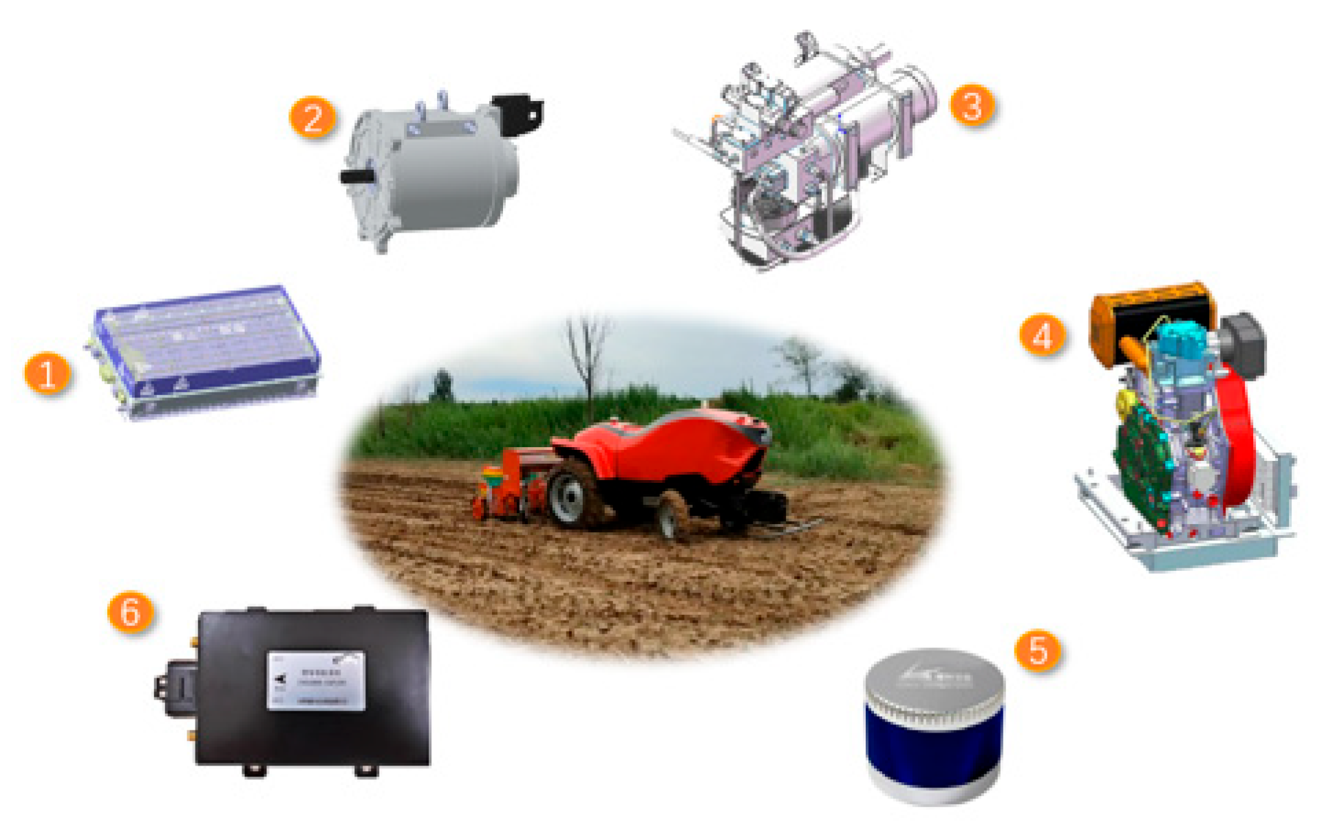
2.1.1. Extended-Range Electric Tractor Architecture

The architecture of ARET is shown in Figure 1. Central electric drive control was adopted, the whole machine was controlled by a central domain controller, and the system integrated a satellite navigation automatic driving system, electric drive system, power battery, range extender, line control movement, line control steering, network communication, and six modules of agricultural tools. As seen in Figure 1, the power battery, range extender, drive motor, and transmission constitute the main parts of the drive system. An independent hydraulic station was used to control the lifting of sowing tools and complete a series of instructions for unmanned sowing operation.
This paper took corn sowing as an example, which can be applied to wheat and other common crops. The ARET seeding unit included three rows of corn planters. The parameters of the whole unit are shown in Table 1, and the structure of the unit is shown in Figure 2.

2.1.2. Working Condition Modeling

Dynamic Load Dynamics Model of Seeding Unit

The establishment of a tire soil model (Figure 3) is key to the personalized modeling of tractors, and the direct effect of the tractor wheels and soil will affect the tractor’s passing performance, traction performance, sowing efficiency, and operation straightness [19]. The wheel is regarded as a rigid structure, and only the contact deformation between the soil and wheel was considered; the load on different soils such as stubble land and sandy land is also different. The wheel adhesion force of the extended-range electric tractor unit during sowing operation was determined by the analysis of the load, as shown below.
M f = f r Z
Z 1 = G ( L a t ) + F k s i n α + M f q + M f 2 L
Z 2 = G a t F k s i n α M f q M f 2 L
where Mf is the wheel resistance moment, Nm; r is the radius of the wheel, m; f is the rolling resistance coefficient; at is the position of the tractor centroid, m; Fk is the vertical distance from the planter’s center of mass to the ground, m; L is the wheelbase of the front and rear wheels, m.

Cycle Condition

Aiming at the problem of the precise modeling of the working conditions of the extended-range unmanned electric tractor unit, the working conditions can refer to the vehicle cycle working conditions with equal proportion [14], or the data of the whole test process are obtained directly through field tests of divided working conditions [13]. Due to the great gap between the soil environmental conditions and asphalt pavement during tractor sowing and transportation, ideal cycle conditions can be difficult to simulate soil resistance changes during tractor field trials [19,20,21], so in this paper, the sowing conditions were divided by test data, as shown in Figure 4a. Figure 4b shows the GUI monitoring interface of the ARET driverless mode operation. By using the RTK base station to locate the four angular latitude and longitude coordinates of the plot in advance and measure the area, path planning can be carried out independently, and the land utilization rate can be rationally used including the choice of head turning type to increase the energy utilization rate.

2.2. Key Components Design of an Extended-Range Electric Tractor
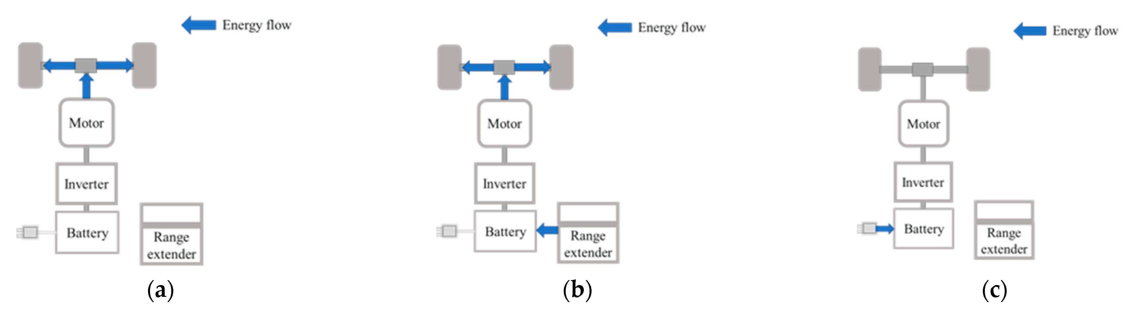
2.2.1. Driving Mode

In this paper, ARET has two energy sources, the battery and range extender, while the drive system has three driving modes [22], namely, the pure electric drive mode, range extender mode, and stop-charge mode. The energy flow of different driving modes is shown in Figure 5.

2.2.2. Traction Motor Design

The dynamic requirements of the tractor and the traction resistance were analyzed according to the characteristics of the driverless electric tractor operating under the sowing condition. During sowing, the resistance of the ditcher was taken as the main source of resistance, and the dynamic modeling and force analysis were carried out on the resistance of the ditcher [20,21]. The resistance equation including soil parameters, ditcher structure parameters, and working characteristics parameters was established. In addition, although the prototype did not include the function of the electronically controlled soil insertion angle according to the resistance equation [20,21], this paper simulated the resistance obtained by the ditcher angle during soil sowing through Adams and EDEM software to obtain the optical angle, and analyzed the resistance during 20~40° insertion, as shown in Figure 6.
Through analysis, it was found that the adjustment resistance of the suspension device decreased gradually with the increase of the ditching angle, but the resistance did not decrease significantly after the ditching angle was 35°. The maximum resistance at the insertion angle of 35° was 118.84 N and the average value was 85.54 N, and the maximum resistance at the insertion angle of 40° was 115.08 N and the average value was 71.14 N; the force fluctuation was large when the insertion angle of 40° was taken into account. Therefore, the insertion angle of 35° was fixed. Considering the performance of connected agricultural machinery and tools and the change in working environment, a 10%~20% reserve should be reserved for average resistance [15]. The traction power can be calculated according to the traction resistance.
F T = ( 1.1 ~ 1.2 ) F K
P r = F T v T 3.6 η T
where FK is the traction resistance, N; vT is the operating speed, km/h; ηT is the traction efficiency.
According to the design tractive force index to calculate the power [22,23,24], we can find the rated motor speed ne under the same working condition per experience. We can calculate the rated torque as:
T e = 9550 P r n e
Due to the complex multi-gear transmission of the electric tractor, it is not suitable for gear shifting when the unmanned electric tractor is working. This machine adopts the method of optimizing the reduction ratio of the unique gear ratio to close the gear-shifting. The driving motor is installed at the input end of the transmission to realize the deceleration drive. The original eight forward gear and eight reverse gear modes are fixed in the third gear mode, and the sowing speed of the unmanned tractor is adjusted by the speed of the motor to realize a continuously variable speed [25]. The transmission of third gear model chooses from all levels of the original tractor shift, as seen in Table 2. The tractor transmission ratio is designed according to the sowing condition [15] as follows:
i 3 = 0.377 n e r i 0 v T
where r is the driving wheel radius, m; i0 is the speed ratio of the main reducer.
The external characteristic curve and efficiency map of the selected motor are shown in Figure 7.

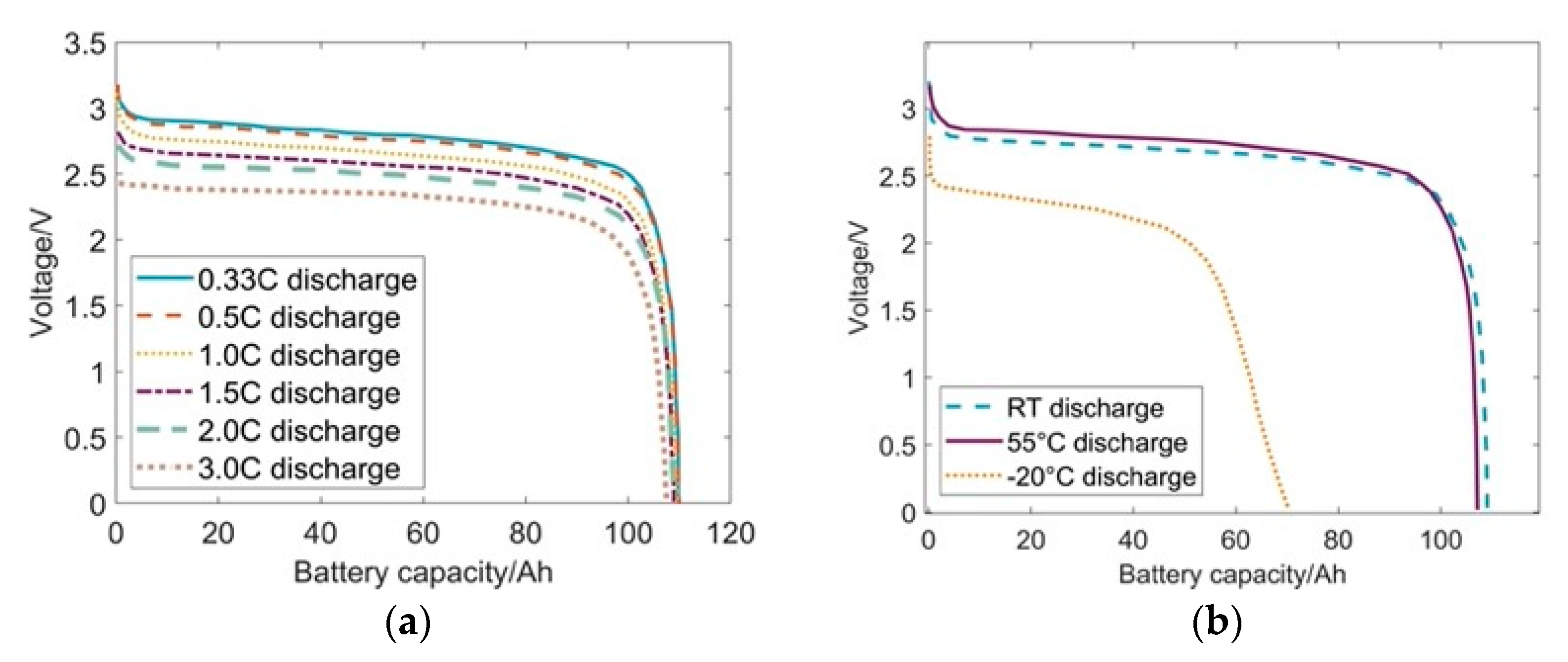
2.2.3. Power Battery Design

Due to the complex working condition of the unmanned electric tractor and the fact that the important parts are difficult to disassemble, the lithium iron phosphate battery was selected as the power battery, which has the characteristics of safety, high temperature resistance, large capacity, and so on.
The work by the tractor to overcome the resistance is:
W l = ( F k + f m g c o s α + 1 2 C D A ρ v T ) S
where CD is the air drag coefficient; A is the windward area, m2; ρ is the air density, kg/m3.
Battery power:
Q l = 1000 W l U l
Therefore, the lithium iron phosphate battery should meet the following two conditions: W ≥ Wl and Q ≥ Ql. Ignoring the thermal effect and transient effects of batteries, this paper introduced a simplified Rint battery model, and the state of battery charge is:
S O C ( t ) = S O C 0 + t 0 t U V O C 2 U V O C 2 4 R B P B 2 R B Q B d t
where SOC is the SOC value at initial time; UVOC is the open-circuit battery voltage, V; RB is the battery internal resistance, Ω; PB is the battery output power, kW; QB is the battery capacity, Ah.
The battery curve is shown in Figure 8:

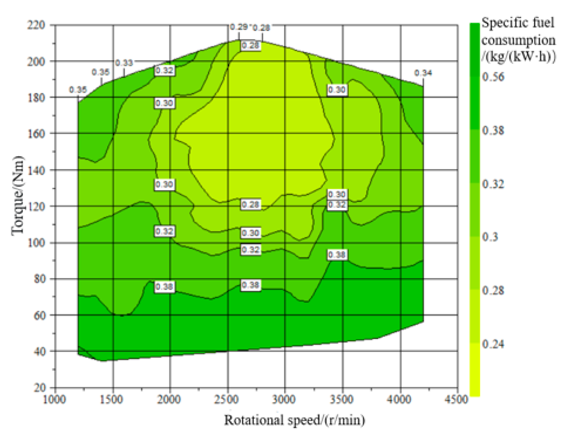
2.2.4. Design of Range Extender

The engine/generator is the main functional unit of ARET, which mainly meets the working requirements of agricultural operations and avoids emergencies such as the shelving of remaining operations due to power depletion during operation. When the SOC value of the battery drops to the lower limit, the range extender opens for auxiliary charging. The design of the range extender needs to meet the power of the unmanned tractor and the power consumption of the unmanned equipment (P0) when operating continuously for a long time. Therefore, its design value is:
P Z = P T + P 0 η E
where ηE is the transmission efficiency. The universal characteristic curve of the engine is shown in Figure 9.

2.3. Energy Management Strategies

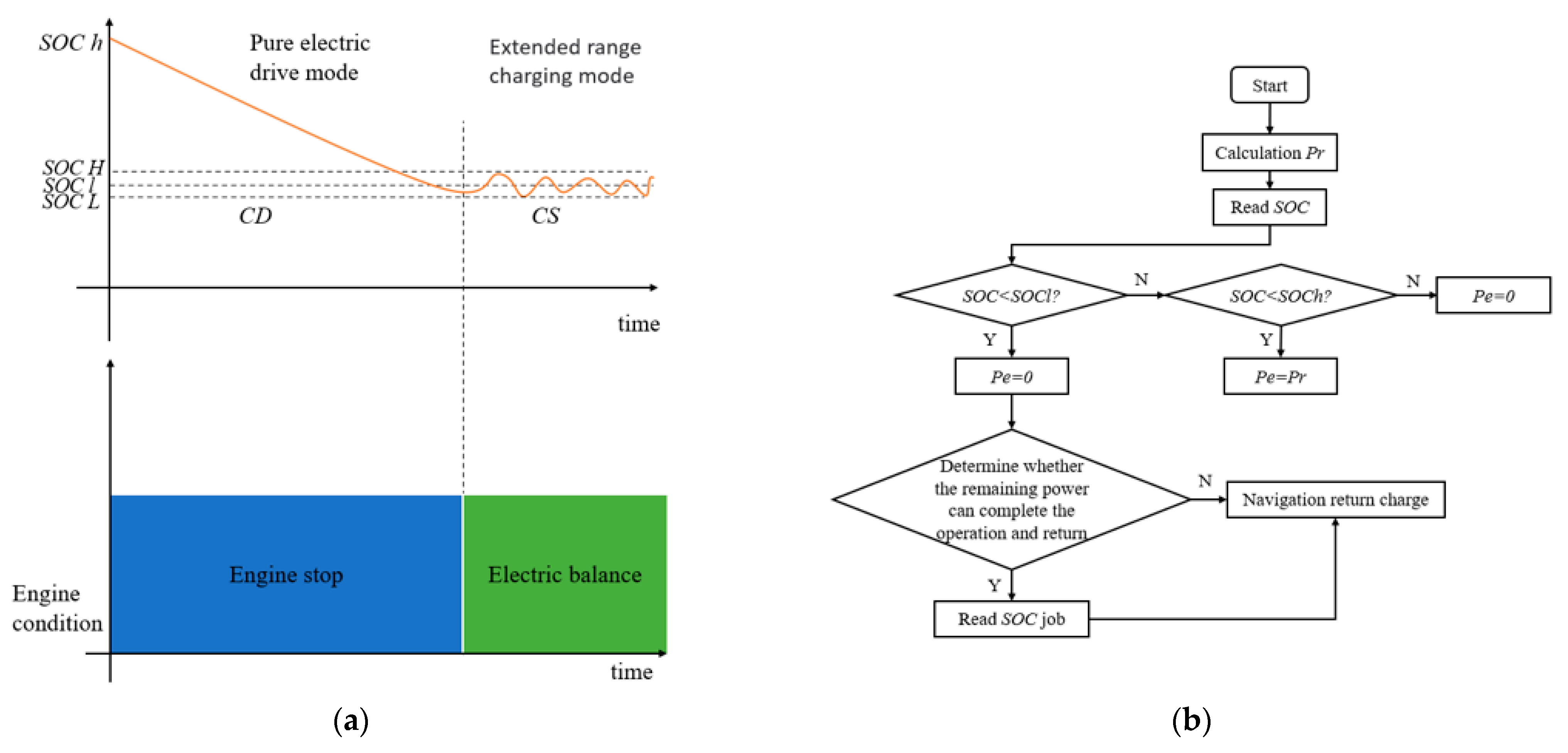
2.3.1. Rule-Based Energy Management Strategy

Since ARET often work in an unmanned environment, in order to ensure the good driving performance of an ARET, two stages of control were adopted based on the traditional power following strategy [26,27]: the first stage is the pure electric drive stage, and the power consumption mode is the CD stage, where the SOC value of the battery continues to decrease from the initial value to the lower threshold of SOC; in the second stage, the range extender starts to work. In order to avoid frequent engine starts and stops, which may cause the SOC of the lithium battery pack to be in a low state for a long time, leading to the phenomenon of discharge occurring in some working conditions, where the range extender continues to open and enters the CS stage of the power maintenance mode. SOC low and SOC high were set to protect the phenomenon of over-discharge or under-discharge of the battery. The SOC of the battery was maintained close to SOCl, and the SOC correction coefficient of its maintenance stage was controlled, as seen in Figure 10. The establishment of direct switching strategies for different driving modes is shown in Figure 11 and the overall specific rules are shown in Figure 12.
In CS mode, the charging state is maintained, and a signal is given to adjust the engine to generate additional power to SOCl.

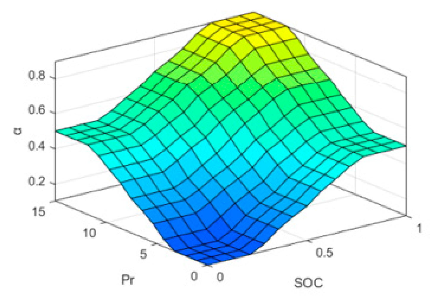
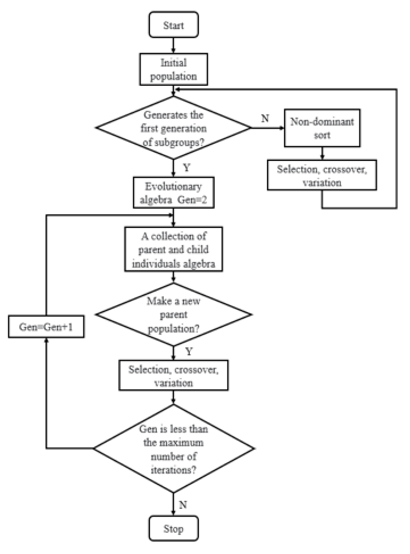
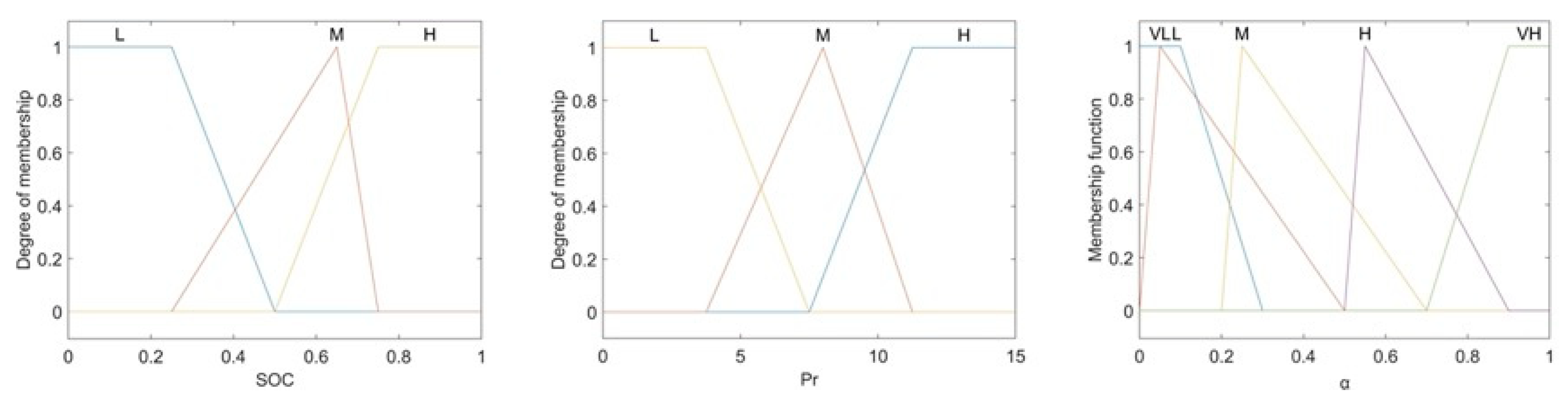
2.3.2. Fuzzy Adaptive Energy Management Strategy

In order to achieve a better control effect, the fuzzy control strategy was further studied on the basis of a regular algorithm [28]. The policy model is shown in Figure 13. Because the fuzzy rules replace the clear rules when necessary, these can be adjusted to improve the freedom of control. The fuzzy logic principle is shown in Figure 14. The fuzzy controller establishes fuzzy rules for the rule-based power consumption and power maintenance strategy SOC. Three-dimensional logical rule surfaces are shown in Figure 15. The control structure has two input variables including Pr and SOC, the fuzzy subset is the [L, M, H] single output, the SOC correction coefficient α, and the fuzzy subset is [VL, L, M, H, VH]. Table 3 shows specific logical rules and Figure 16 shows the membership function rules established.
The fuzzy controller uses the gravity center method to solve the fuzzy, and the fuzzy output ui is:
u i = i = 1 m u i μ u ( u i ) i = 1 m μ u ( u i )
Since the membership function is determined according to experience, considering the economic requirements, the energy consumption was taken as the fitness function to optimize the vertex coordinates of the membership function. The fuzzy controller was optimized by the NSGA-II algorithm. The principle of the NSGA-II algorithm is shown in Figure 17, and the optimization results are shown in Figure 18.
min J = 0 t [ u ( t ) * i ( t ) ) ] s t . S O C L S O C ( t ) S O C H P e _ min P e ( t ) P e _ max P b a t _ f P ess ( t ) P b a t _ c
where Pe is the engine power, kW; Pess is the battery power, KW; Pbat_f and Pbat_c indicate the battery charging and discharging power, kW, respectively.

3. Results and Discussion

3.1. Hardware-In-The-Loop Test and Simulation Model

In the simulation test, the overall model was built in Cruise software and the strategy model was built in Simulink for co-simulation, as shown in Figure 19. The built AVL-Cruise vehicle simulation model was transferred to Simulink by generating CMC files through the CMC function, and corresponding interfaces were defined in the Simulink model. Then, through the real-time workspace RTW (Real Time Workshop) function of MATLAB/Simulink, the C code was generated for the vehicle model and downloaded to the simulator. On the other hand, C code was generated by VS for the good decision control strategy built in MATLAB/Simulink, and the compiled executable file was downloaded. Finally, the signal interaction between the controller and the controlled object was carried out through the CAN bus interface [28,29,30], as shown in Figure 20.

3.2. Data Analysis

Based on the speed condition of the field experiment in the stubble field, the test was carried out, and the cycle was carried out 20 times. The proposed CD-CS strategy and the optimized fuzzy strategy were compared and analyzed, and the analysis results are presented in Figure 21.
Since all the strategies proposed are based on the power consumption stage, the range extender works as the auxiliary power source to improve the power utilization rate. It can be seen from Figure 22 that both strategies could maintain the SOC close to 50% in the power maintenance stage. Compared with the original strategy, the fuzzy strategy proposed had a better maintenance effect, with the fuzzy strategy maintaining close to 49.9% and the CD-CS strategy maintaining near 49.5%. Compared with the CD-CS strategy, the SOC fluctuation of the fuzzy control strategy was smoother, and the proposed fuzzy SOC correction factor strategy extended the battery life of the power consumption phase by 2131.9 s, which had a superior effect. At the end of the power consumption stage, the proposed CD-CS strategy had an obvious upward trend in the way that the SOC correction factor was determined by the tabular-looking method, while the fuzzy strategy output the SOC correction factor by the fuzzy control, achieving an adaptive adjustment effect. The SOC curve was smooth from the power consumption stage to the power maintenance stage. It was found that the motor torque, current, and other parameters increased obviously when the ditcher of the extended-range electric tractor unit was put into soil. In addition, in terms of fuel consumption, the analysis of the truncated cycle segment curve showed that the proposed fuzzy strategy was more stable than the CD-CS strategy.

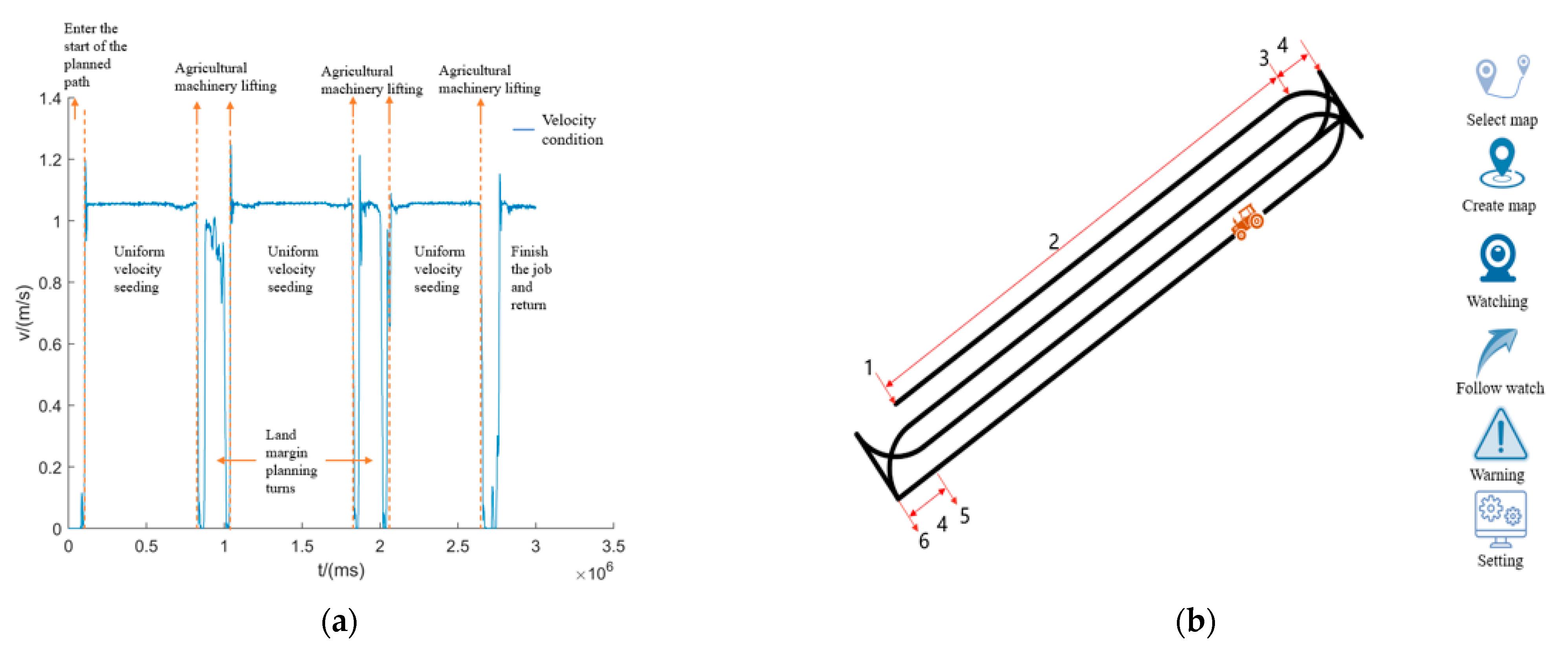
3.3. Field Experiment

In order to verify the rationality and accuracy of the proposed fuzzy control strategy and whether it could meet the agronomic requirements in a real sowing environment, corn sowing experiments were carried out in the experimental field based on the prototype developed by the research group, and the experimental environment was a wheat stubble field. The test steps are as follows:
(1)
Before the test, measure the size of the plot and estimate the seeding area;
(2)
Input the geographical information of the four points of the plot by the map point acquisition device, and generate a sowing area map. The real-time information is then read and input into the database through the CAN card connected to the computer, and the navigation detection interface is opened to monitor the navigation state;
(3)
According to the measured map, use the planning path interface to input the operation width and vehicle overall parameters, divide the sowing area, and plan the path;
(4)
Enter the unmanned mode and input the specified starting point for the test. Save the data after seeding and enter the CANmc monitoring interface to read the data. The specific process is shown in Figure 22, and Figure 23 shows the test photo of the tractor unit.
The extracted test data and simulation data were compared and analyzed, as shown in Figure 24. The time in the figure corresponds to the first cycle of the test data. As can be seen from the motor speed curve, there was little difference between the simulation test speed and the actual test speed, and the average error was 52.6 r/min, which was within the acceptable range. As can be seen from the motor torque curve, its average error was 4.5 Nm. The torque curve was not in good agreement with the simulation test results, and the actual torque will be larger due to the influence of landform changes and other factors in the actual operation. As can be seen from the voltage and current curve, the voltage curve and the simulation data had a high coincidence, the current curve was poor due to the influence of actual unmanned driving and other components and electrical equipment as well as the complexity and variability of soil, which led to the deviation between the results and the expected results, but was within the acceptable range.
A comprehensive comparison between the actual test and the simulation test results showed that the simulation and the actual curves were in good alignment. The simulation model could be well-applied to the whole vehicle test. In terms of the power consumption in a cycle, the SOC decreased by 7.21% in the field test and 4.94% in the simulation. The power consumption error was within a reasonable range, which further verifies the feasibility of the energy management model of the sowing unit of an unmanned electric tractor with the fuzzy strategy.

4. Conclusions

From the above research and analysis, the conclusions of this paper can be summarized by the following three points.
(1)
According to the sowing agronomic requirements of the unmanned agricultural machinery group, the whole machine model of the extended-range unmanned electric tractor was established to analyze the influence curve of the furrow angle on the whole machine resistance under the seeding condition, and transmission gear sealing and a constant speed ratio were adopted to realize the continuously variable speed.
(2)
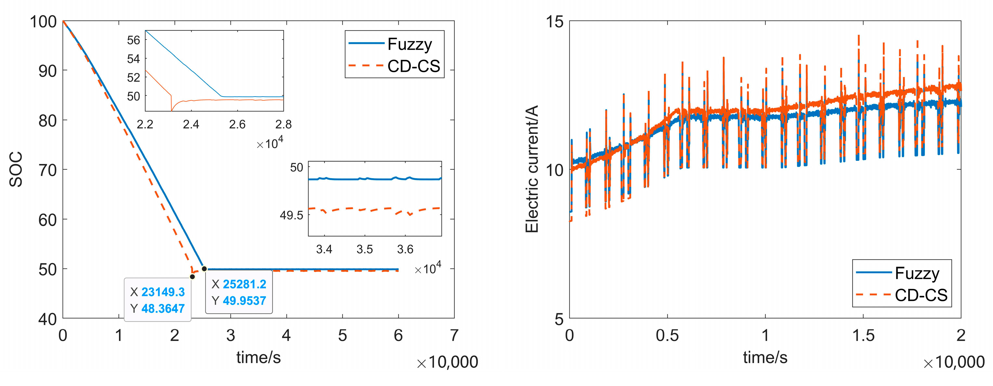
According to the requirements of sowing agronomy, electric energy consumption is the main, fuel consumption is the auxiliary, and the purpose is to extend the battery life under the mode of pure electric drive. For improved power following the energy management strategy, a power consumption and power maintenance mode energy management strategy was proposed by adding a fuzzy control strategy with the aim at increasing mileage, optimizing the SOC correction factor to improve this strategy. The NSGA-II algorithm was used to optimize the fuzzy controller with the objective function of prolonging the working time in the power consumption stage. The simulation results of the proposed fuzzy strategy showed that prolonging the battery life of the battery consumption stage was 2131.9 s, which is a superior improvement.
(3)
By using the fuzzy strategy, the comparison between the actual test and simulation results showed that the SOC decreased by 7.21% in terms of power consumption in a cycle, while the simulation power consumption decreased by 4.94%. The power consumption error was within a reasonable range, which further verifies the feasibility of the established energy management model of the extended-range unmanned electric tractor seeding unit with a fuzzy strategy.

Author Contributions

Conceptualization, Z.W. and J.W.; Methodology, Z.W. and J.W.; Software, Z.W. and J.W.; Validation, Z.W. and C.Z.; Formal analysis, Z.W.; Investigation, S.L.; Resources, J.Y. and Y.X.; Data curation, J.Y. and Y.X.; Writing—original draft preparation, Z.W.; Writing—review and editing, Z.W., J.W. and J.Y.; Visualization, Z.W.; Supervision, J.W.; Project administration, J.Y. and C.Z.; Funding acquisition, C.Z. All authors have read and agreed to the published version of the manuscript.

Funding

This work was supported by the Key Technology Research and Intelligent Equipment Research of an unmanned corn planter in Hebei Province (21327203D); Integrated Application of Key Technologies and Intelligent Equipment of Automatic Wheat Precision Planter (22327202D).

Institutional Review Board Statement

Not applicable.

Data Availability Statement

Not applicable.

Acknowledgments

The authors gratefully acknowledge the editors and anonymous reviewers for their constructive comments on our manuscript.

Conflicts of Interest

The authors declare no conflict of interest.

References

  1. Xie, B.; Wu, Z.; Mao, E. Development and prospect of key technologies on agricultural tractor. Trans. Chin. Soc. Agric. Mach. 2018, 49, 1–17. [Google Scholar]
  2. Zhan, W. Unmanned Dense Planting of Wheat Planting Design and Test of the Unit; Hebei Agricultural University: Baoding, China, 2022. [Google Scholar]
  3. Gonzalez-De-Soto, M.; Emmi, L.; Benavides, C.; Garcia, I.; Gonzalez-De-Santos, P. Reducing air pollution with hybrid-powered robotic tractors for precision agriculture. Biosyst. Eng. 2016, 143, 79–94. [Google Scholar] [CrossRef]
  4. Wang, H.; He, H.; Sun, L. Energy Consumption Analysis and Energy Management Strategy of a Pure Electric Cleaning Vehicle. J. Automot. Eng. 2022, 12, 137–146. [Google Scholar]
  5. Chen, H.; Xie, H.; Sun, L.; Shang, T. Research on Tractor Optimal Obstacle Avoidance Path Planning for Improving Navigation Accuracy and Avoiding Land Waste. Agriculture 2023, 13, 934. [Google Scholar] [CrossRef]
  6. Varshney, A.; Goyal, V. Re-evaluation on fuzzy logic controlled system by optimizing the membership functions. Mater. Today Proc. 2023, in press. [Google Scholar] [CrossRef]
  7. Climent, H.; Pla, B.; Bares, P.; Pandey, V. Exploiting driving history for optimizing the energy management in plug-in hybrid electric vehicles. Energy Convers. Manag. 2021, 234, 113919. [Google Scholar] [CrossRef]
  8. Bai, Y.; He, H.; Li, J.; Li, S.; Wang, Y.X.; Yang, Q. Battery Anti-Aging Control for a Plug-in Hybrid Electric Vehicle with a Hierarchical Optimization Energy Management Strategy. J. Clean. Prod. 2019, 237, 117841. [Google Scholar] [CrossRef]
  9. Bayindir, K.Ç.; Gözüküçük, M.A.; Teke, A. A comprehensive overview of hybrid electric vehicle: Powertrain configurations, powertrain control techniques and electronic control units. Energy Convers. Manag. 2011, 52, 1305–1313. [Google Scholar] [CrossRef]
  10. Zhang, S.-L.; Wen, C.-K.; Ren, W.; Luo, Z.-H.; Xie, B.; Zhu, Z.-X.; Chen, Z.-J. A joint control method considering travel speed and slip for reducing energy consumption of rear wheel independent drive electric tractor in ploughing. Energy 2023, 263, 126008. [Google Scholar] [CrossRef]
  11. Xu, L.; Zhang, J.; Liu, M.; Zhou, Z.; Liu, C. Control algorithm and energy management strategy for extended range electric tractors. Int. J. Agric. Biol. Eng. 2017, 10, 35–44. [Google Scholar] [CrossRef]
  12. Fang, S.; Zhou, Z.; Xu, L. Energy Management Strategy of Series Hybrid Tractors. J. Henan Univ. Sci. Technol. Nat. Sci. Ed. 2015, 36, 61–66. [Google Scholar]
  13. Wang, Z.; Zhou, J.; Wang, X. Design and experiment of energy management model for rototiller group of extended range electric tractor. J. Agric. Mach. 2023, 13, 1–10. [Google Scholar]
  14. Zhang, J.; Feng, G.; Xu, L.; Wang, W.; Yan, X.; Liu, M. Energy Saving Control of Hybrid Tractor Based on Pontriagin Minimum Principle. World Electr. Veh. J. 2023, 14, 27. [Google Scholar] [CrossRef]
  15. Zhang, X. Design Theory and Performance Analysis of Electric Tractor Drive System. Int. J. Eng. Res. Technol. IJERT 2017, 6, 235–238. [Google Scholar]
  16. Li, T.H.; Xie, B.; Wang, D.Q.; Zhang, S.L.; Wu, L.P. Real-time Adaptive Energy Management Strategy for Electric Tractor Driven by Two Motors. Trans. Chin. Soc. Agric. Mach. 2020, 51, 530–543. [Google Scholar]
  17. Liu, M.; Lei, S.; Zhao, J.; Meng, Z.; Zhao, C.; Xu, L. Review of Development history and Research Status of Electric Tractor. Trans. Chin. Soc. Agric. Mach. 2022, 53, 348–364. [Google Scholar]
  18. Yu, Y.; Sun, Y.; Xia, C.; Han, J.; Shi, J.; Gao, H. Dual-layer fuzzy control energy Management Strategy for fuel cell vehicles. J. Chongqing Univ. Technol. Nat. Sci. 2022, 36, 21–28. (In Chinese) [Google Scholar]
  19. Yang, M.; Sun, X.; Deng, X.; Lu, Z.; Wang, T. Extrapolation of Tractor Traction Resistance Load Spectrum and Compilation of Loading Spectrum Based on Optimal Threshold Selection Using a Genetic Algorithm. Agriculture 2023, 13, 1133. [Google Scholar] [CrossRef]
  20. Qiu, Z.; Ma, Y.; Jin, X.; Ji, J.; He, Z. Dynamic modeling and Simulation of High Speed Trenching Resistance of Wheat planter. J. Agric. Mech. Res. 2019, 41, 52–58+109. [Google Scholar]
  21. Zhang, S.; Ren, W.; Xie, B.; Luo, Z.; Wen, C.; Chen, Z.; Zhu, Z.; Li, T. A combined control method of traction and ballast for an electric tractor in ploughing based on load transfer. Comput. Electron. Agric. 2023, 207, 107750. [Google Scholar] [CrossRef]
  22. Kang, H.; Jung, D.; Kim, M.; Min, K. Study of energy management strategy considering various working modes of plug-in hybrid electric tractor. Trans. Korean Soc. Mech. Eng. B 2013, 37, 181–186. [Google Scholar] [CrossRef] [Green Version]
  23. Zhu, Z.; Yang, Y.; Wang, D.; Cai, Y.; Lai, L. Energy saving performance of agricultural tractor equipped with Mechanic-Electronic-Hydraulic powertrain system. Agriculture 2022, 12, 436. [Google Scholar] [CrossRef]
  24. Yu, Y.; Hao, S.; Guo, S.; Tang, Z.; Chen, S. Motor Torque Distribution Strategy for Different Tillage Modes of Agricultural Electric Tractors. Agriculture 2022, 12, 1373. [Google Scholar] [CrossRef]
  25. Kim, N.; Rousseau, A.; Rask, E. Autonomie model validation with test data for 2010 Toyota Prius. Fuel 2012, 48, 46. [Google Scholar]
  26. Lee, H.S.; Kim, J.S.; Park, Y.I.; Cha, S.W. Rule-based power distribution in the power train of a parallel hybrid tractor for fuel savings. Int. J. Precis. Eng. Manuf.-Green Technol. 2016, 3, 231–237. [Google Scholar] [CrossRef]
  27. Shen, P.; Zhao, Z.; Zhan, X.; Li, J.; Guo, Q. Optimal energy management strategy for a plug-in hybrid electric commercial vehicle based on velocity prediction. Energy 2018, 155, 838–852. [Google Scholar] [CrossRef]
  28. Li, P.; Jiao, X.; Li, Y. Adaptive real-time energy management control strategy based on fuzzy inference system for plug-in hybrid electric vehicles. Control Eng. Pract. 2021, 107, 104703. [Google Scholar] [CrossRef]
  29. Mocera, F. A model-based design approach for a parallel hybrid electric tractor energy management strategy using hardware in the loop technique. Vehicles 2020, 3, 1–19. [Google Scholar] [CrossRef]
  30. Xie, B.; Wang, S.; Wu, X.; Wen, C.; Zhang, S.; Zhao, X. Design and hardware-in-the-loop test of a coupled drive system for electric tractor. Biosyst. Eng. 2022, 216, 165–185. [Google Scholar] [CrossRef]
Figure 1. The ARET vehicle architecture.
Agriculture 13 01303 g001
Figure 2. Schematic diagram of the ARET unit.
Agriculture 13 01303 g002
Figure 3. Simplified dynamics model of the ARET seeding unit.
Agriculture 13 01303 g003
Figure 4. Cycle conditions of the seeding operation. (a) Velocity condition. (b) Corresponding speed condition GUI interface: 1. Starting point of path planning (acceleration stage); 2. Uniform seeding stage; 3. Agricultural machinery and tools lifting (excavated deceleration stage); 4. Field planning and turning; 5. Agricultural machinery and tools lifting (excavated deceleration stage); 6. Finish the job and return.
Agriculture 13 01303 g004
Figure 5. ARET driver mode: (a) pure electric drive mode; (b) extended-range mode; (c) parking and charging mode.
Agriculture 13 01303 g005
Figure 6. Influence of the excavation angle on the trenching resistance.
Agriculture 13 01303 g006
Figure 7. External characteristic curve and efficiency map of the motor. (a) External characteristic curve of the motor. (b) Motor efficiency map.
Agriculture 13 01303 g007
Figure 8. Battery curve. (a) Battery discharge curve. (b) Battery temperature discharge curve.
Agriculture 13 01303 g008
Figure 9. Engine universal characteristic curve.
Agriculture 13 01303 g009
Figure 10. Strategy model of the power maintenance stage.
Agriculture 13 01303 g010
Figure 11. The ARET mode switching strategy.
Agriculture 13 01303 g011
Figure 12. Overall framework of the power consumption power maintenance strategy. (a) Principle curve of SOC consumption. (b) ARET overall strategy flowchart.
Agriculture 13 01303 g012
Figure 13. Improved strategy model of fuzzy control.
Agriculture 13 01303 g013
Figure 14. Fuzzy control principle.
Agriculture 13 01303 g014
Figure 15. Rules of 3D fuzzy logic.
Agriculture 13 01303 g015
Figure 16. Membership function of fuzzy control.
Agriculture 13 01303 g016
Figure 17. Schematic diagram of the NSGA-II algorithm.
Agriculture 13 01303 g017
Figure 18. Fuzzy control after optimization.
Agriculture 13 01303 g018
Figure 19. The AVL-Cruise and Simulink co-simulation.
Agriculture 13 01303 g019
Figure 20. Hardware-in-the-loop test diagram: 1. Auxiliary machine; 2. Power; 3. CAN card; 4. VCU; 5. Wiring harness; 6. Testing machine.
Agriculture 13 01303 g020
Figure 21. Comparison curve of the test results.
Agriculture 13 01303 g021aAgriculture 13 01303 g021b
Figure 22. Test process diagram.
Agriculture 13 01303 g022
Figure 23. Test process and prototype demonstration: 1. Battery pack; 2. Motor; 3. Hydraulic station; 4. Range extender; 5. Laser radar; 6. Integrated inertial navigation.
Agriculture 13 01303 g023
Figure 24. Data analysis.
Agriculture 13 01303 g024
Table 1. Important parameters of the ARET device.
ComponentParameterNumerical Value
Vehicle parametersComplete machine quality2060 kg
Radius of front wheel0.382 m
Rear wheel radius0.552 m
Rolling resistance coefficient0.07 (operation)
Wheelbase1.85 m
Connection height0.6 m
MotorRated torque160 Nm
Rated speed6800 r/min
Range extenderRated power30 kW
Battery packBattery cell3.2 V
Voltage144 V
GearboxTotal gear ratio106
Table 2. Gear ratio of the original tractor.
Mode 8 + 8
Forward gearReverse gear
I: 39 17 × 43 20 × 43 20 × 56 12 × 71 14 = 250.975 I: 32 31 × 26 25 × 39 17 × 43 20 × 43 20 × 56 12 × 71 14 = 269.434
II: 25 23 × 43 20 × 43 20 × 56 12 × 71 14 = 166.477 II: 32 31 × 26 25 × 35 23 × 43 20 × 43 20 × 56 12 × 71 14 = 178.721
III: 31 32 × 43 20 × 43 20 × 56 12 × 71 14 = 105.980 III: 32 31 × 26 25 × 31 32 × 43 20 × 43 20 × 56 12 × 71 14 = 113.775
IV: 26 37 × 43 20 × 43 20 × 56 12 × 71 14 = 76.875 IV: 32 31 × 26 25 × 26 37 × 43 20 × 43 20 × 56 12 × 71 14 = 82.529
V: 39 17 × 56 12 × 71 14 = 54.294 V: 32 31 × 26 25 × 39 17 × 56 12 × 71 14 = 58.287
VI: 35 23 × 56 12 × 71 14 = 36.014 VI: 32 31 × 26 25 × 35 23 × 56 12 × 71 14 = 38.663
VII: 31 32 × 56 12 × 71 14 = 22.927 VII: 32 31 × 26 25 × 31 32 × 56 12 × 71 14 = 24.613
VIII: 26 37 × 56 12 × 71 14 = 16.631 VIII: 32 31 × 26 25 × 26 37 × 56 12 × 71 14 = 17.854
Rear power output low speed: 44 13 = 3.385
Rear power output high speed: 41 15 = 2.733
Table 3. Fuzzy logic rules.
PrSOC
LMH
LVLLM
MLMH
HMHVH
Disclaimer/Publisher’s Note: The statements, opinions and data contained in all publications are solely those of the individual author(s) and contributor(s) and not of MDPI and/or the editor(s). MDPI and/or the editor(s) disclaim responsibility for any injury to people or property resulting from any ideas, methods, instructions or products referred to in the content.

