
Study of Potential Application Air Curtains in Livestock Premises at Cattle Management Farms
 ,
,  , ,
, ,  and
and 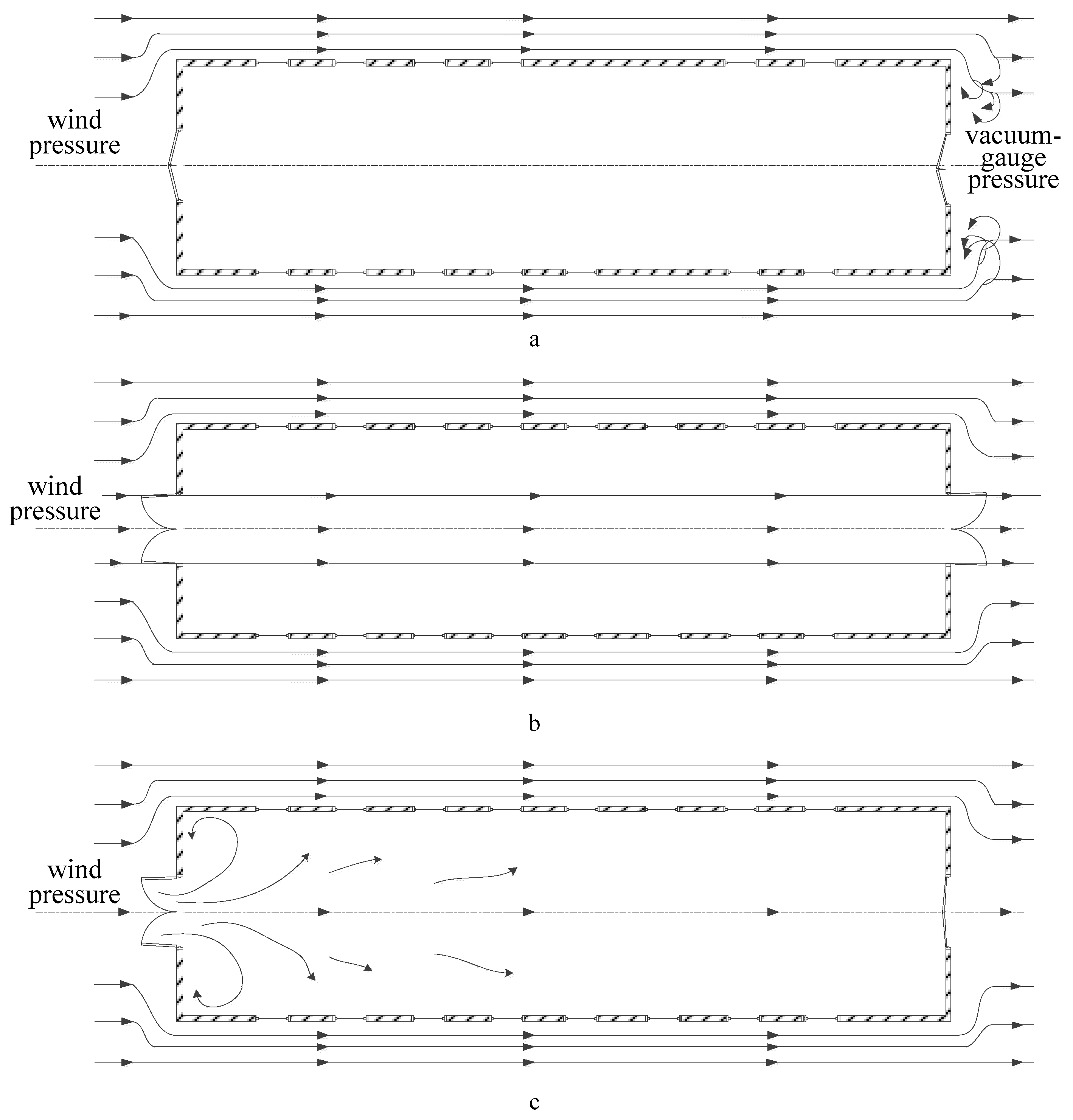
Abstract
:1. Introduction
2. Materials and Methods
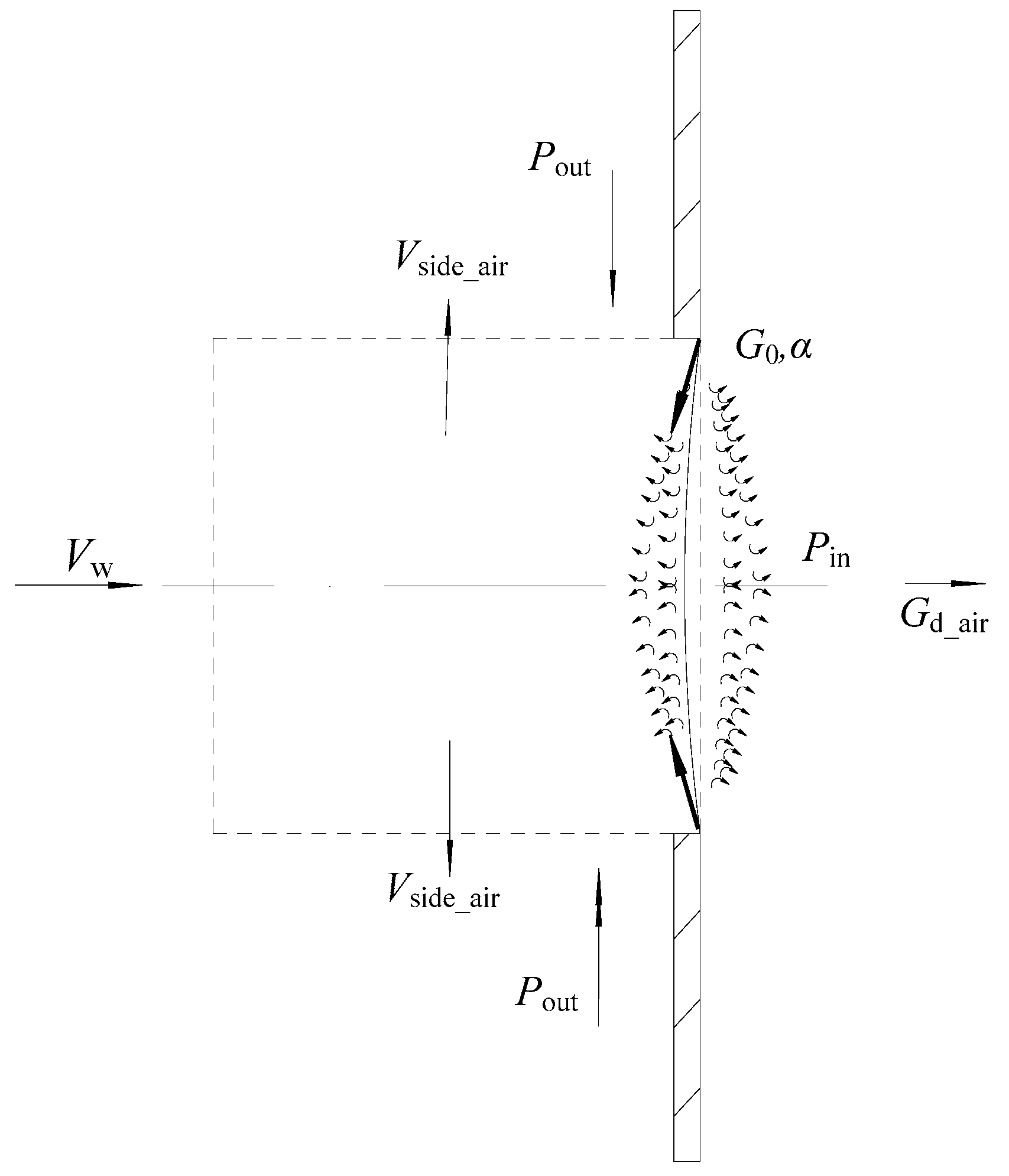
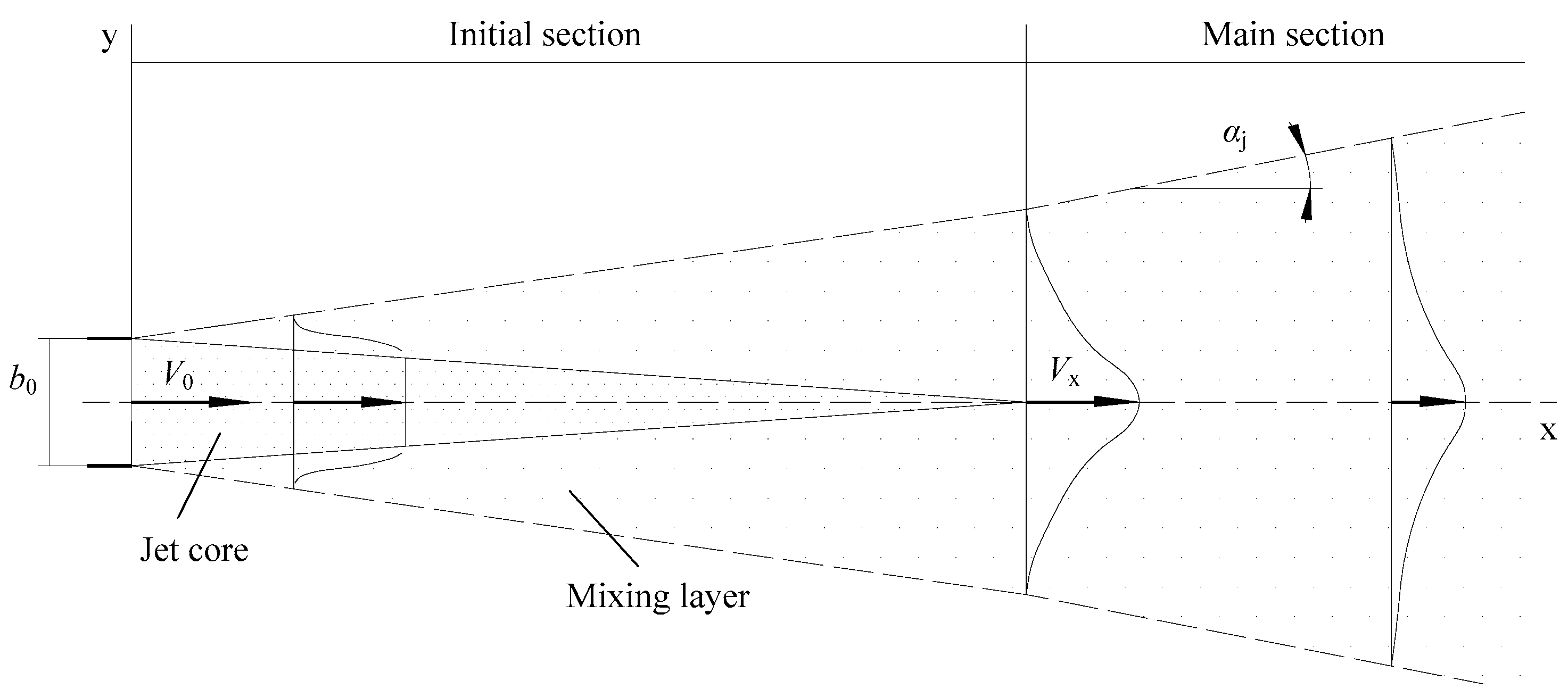
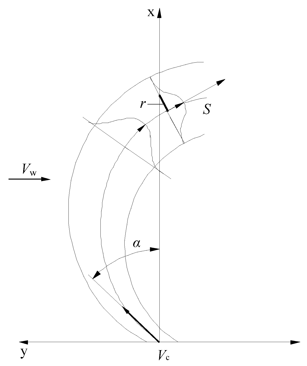
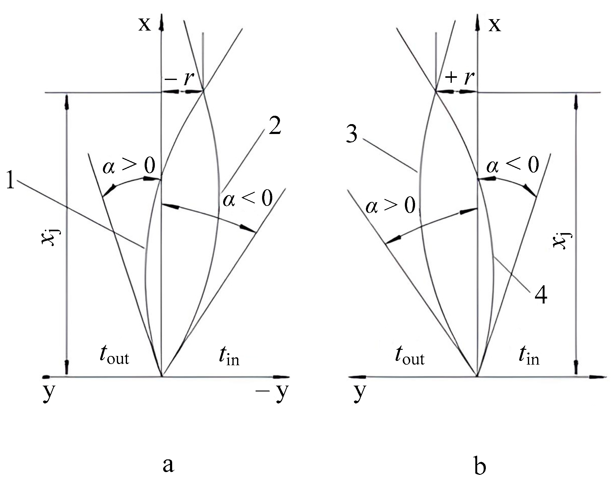
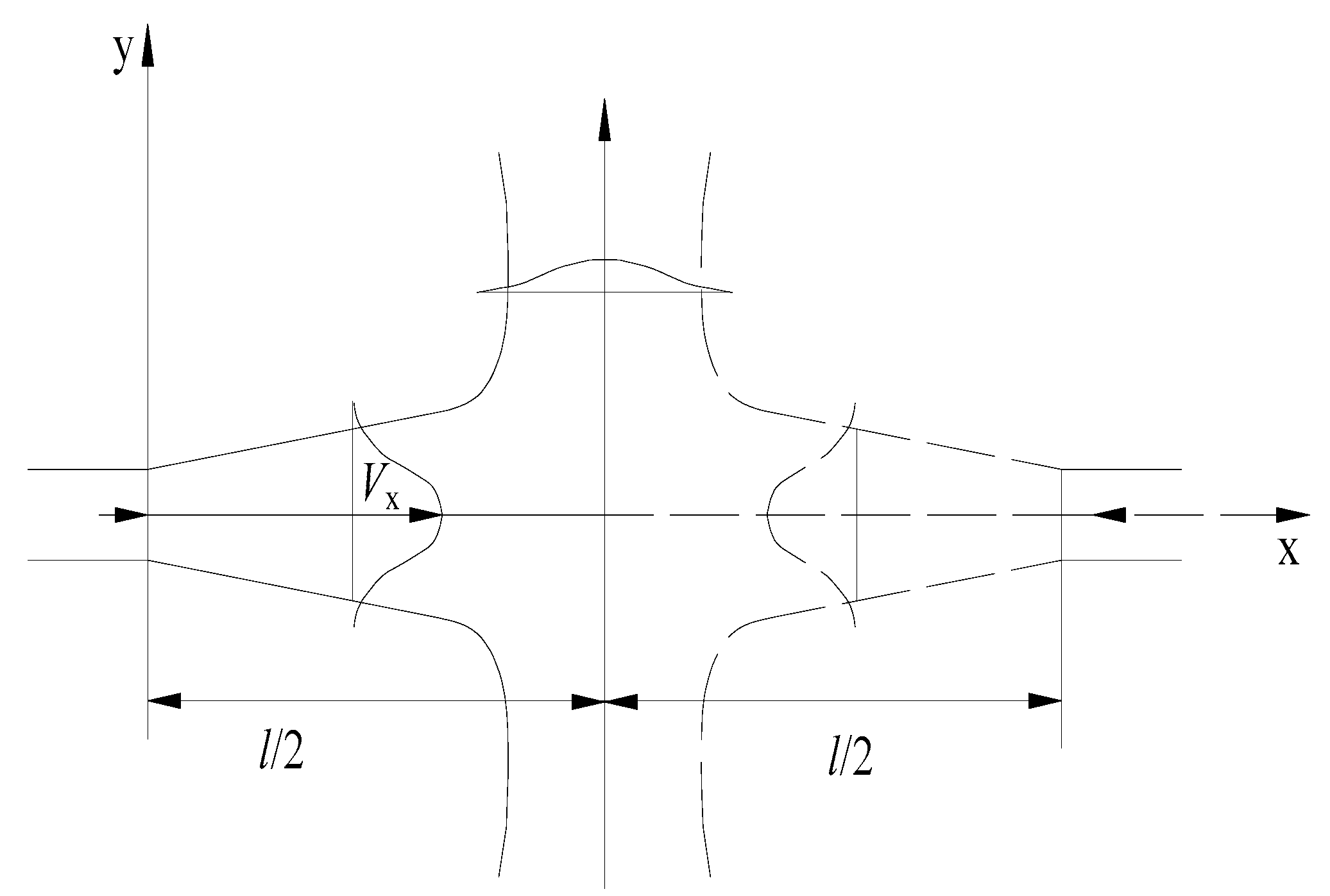
2.1. Theoretical Substantiation of the Air Curtain Operation
- -
- for indoor air intake:
- (1)
- pin < pout—outdoor pressure exceeds that inside the premises, over the entire aperture height;
- (2)
- pin > pout—indoor pressure exceeds that outside the premises, over the entire aperture height.
- -
- for outdoor air intake:
- (3)
- pin < pout—in the bottom part of the aperture;
- (4)
- pin > pout—in the upper part of the aperture.
- -
- The trajectory and position of the air jet axis comply with the condition of the physical model for either counter-moving supply air jets interaction or for a single air jet in a plane perpendicular to the flow (see Figure 6);
- -
- Air jet parameters in the cross-flow, in curvilinear coordinates linked to the air jet axis, are comparable with those of an ordinary immersed jet (air jet effluent into premises filled with air);
- -
- Volumes of air sucked into the jet from both sides are equal to each other, and the volumetric densities of the outdoor and indoor air, as well as that of the air in the air curtain slit output, are assumed to be nearly identical ρin ≈ ρout ≈ ρ0;
- -
- The wind load and air-tightness of premises are taken into account by introducing a certain speed value Vw of a flow perpendicular to the air curtain jet;
- -
- The velocity value of the cross-flow is determined by the difference between the volumetric densities of the outdoor air and of that in the premises is considered as a component of the wind load Vw.
2.2. Theoretical Foundations of Air Curtain Parameters Calculation
3. Results and Discussion
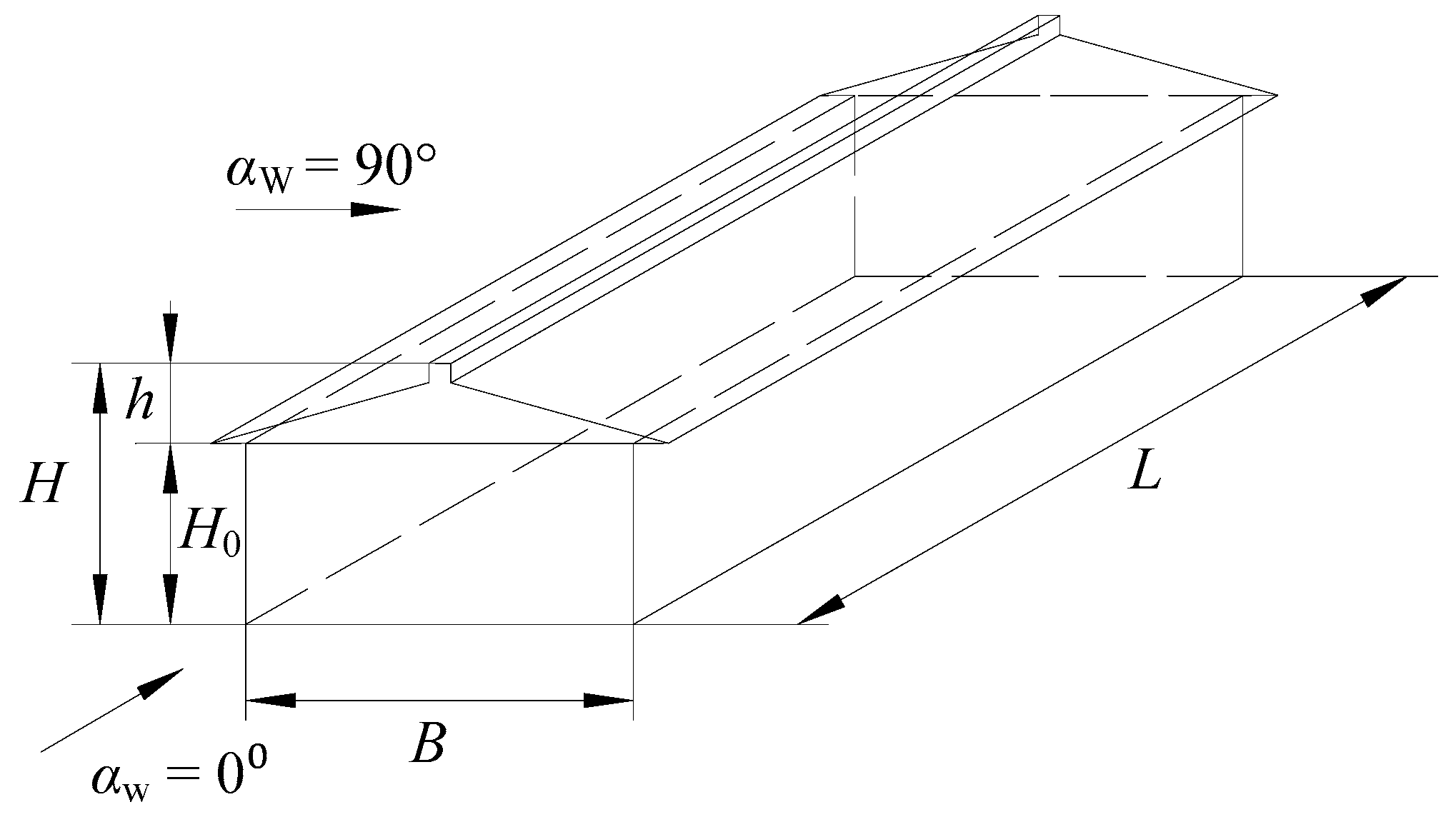
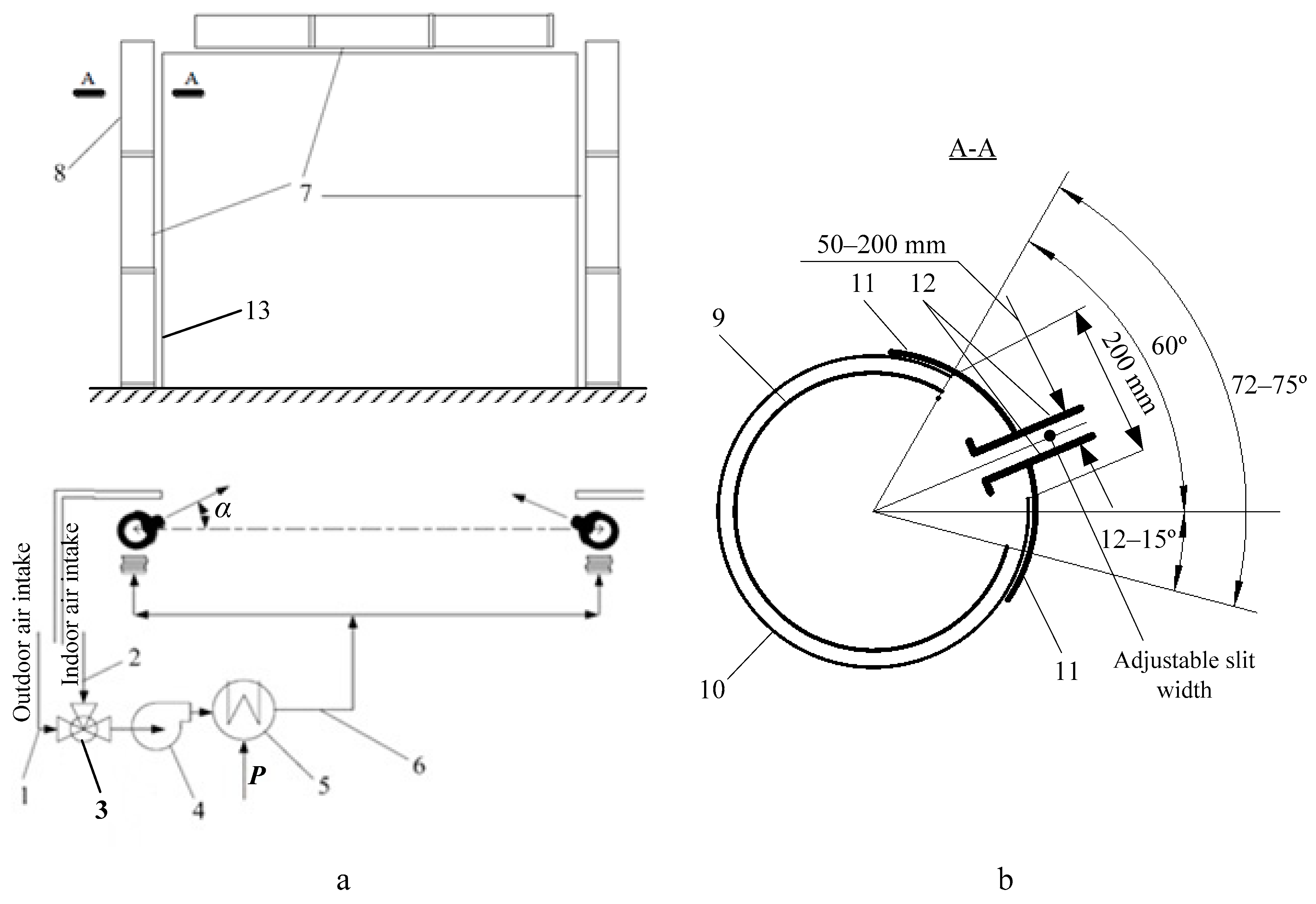
3.1. Designing an Experimental Sample of the Modular Air Curtain
3.2. Results of Tests on the Modular Air Curtain
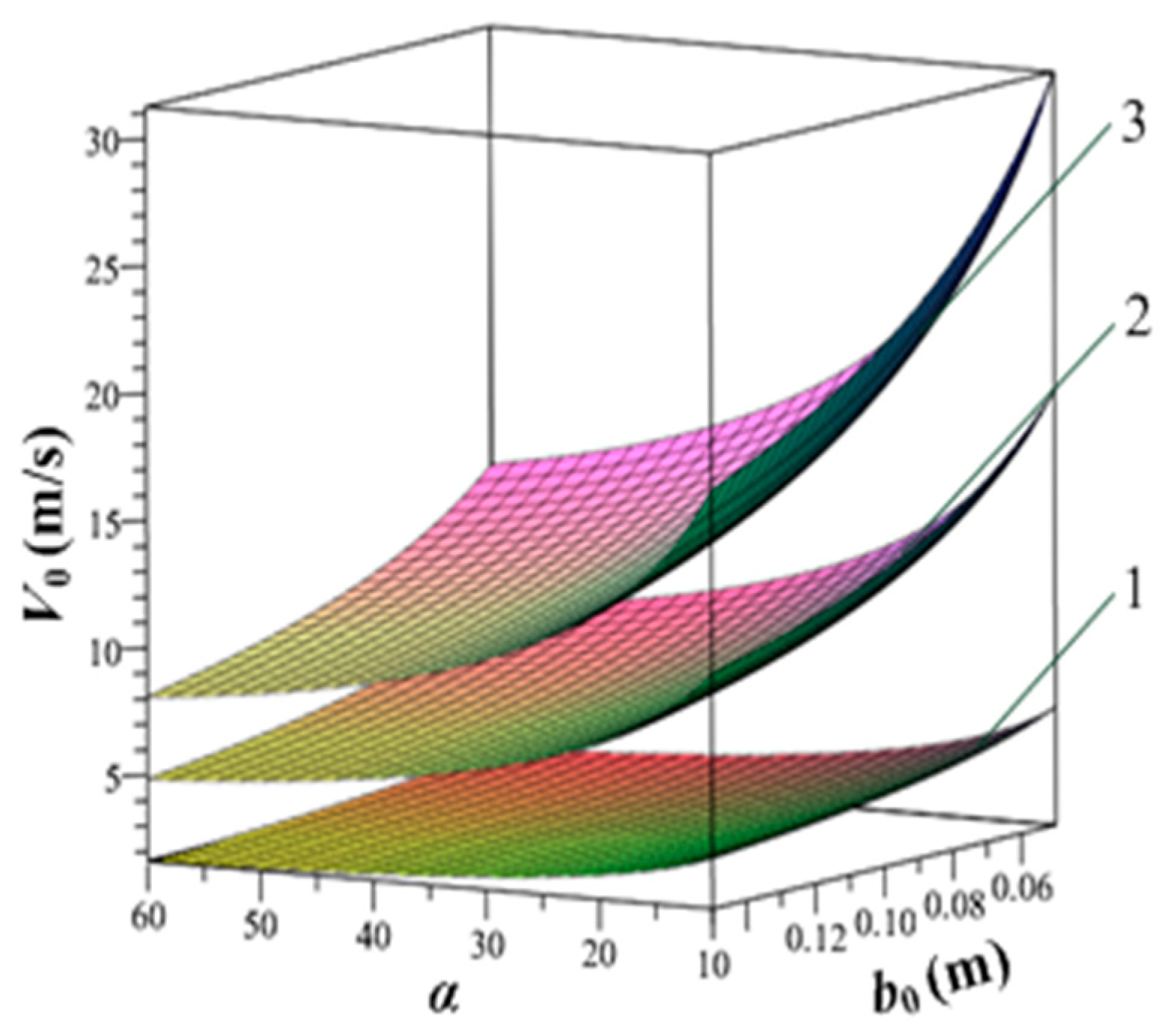
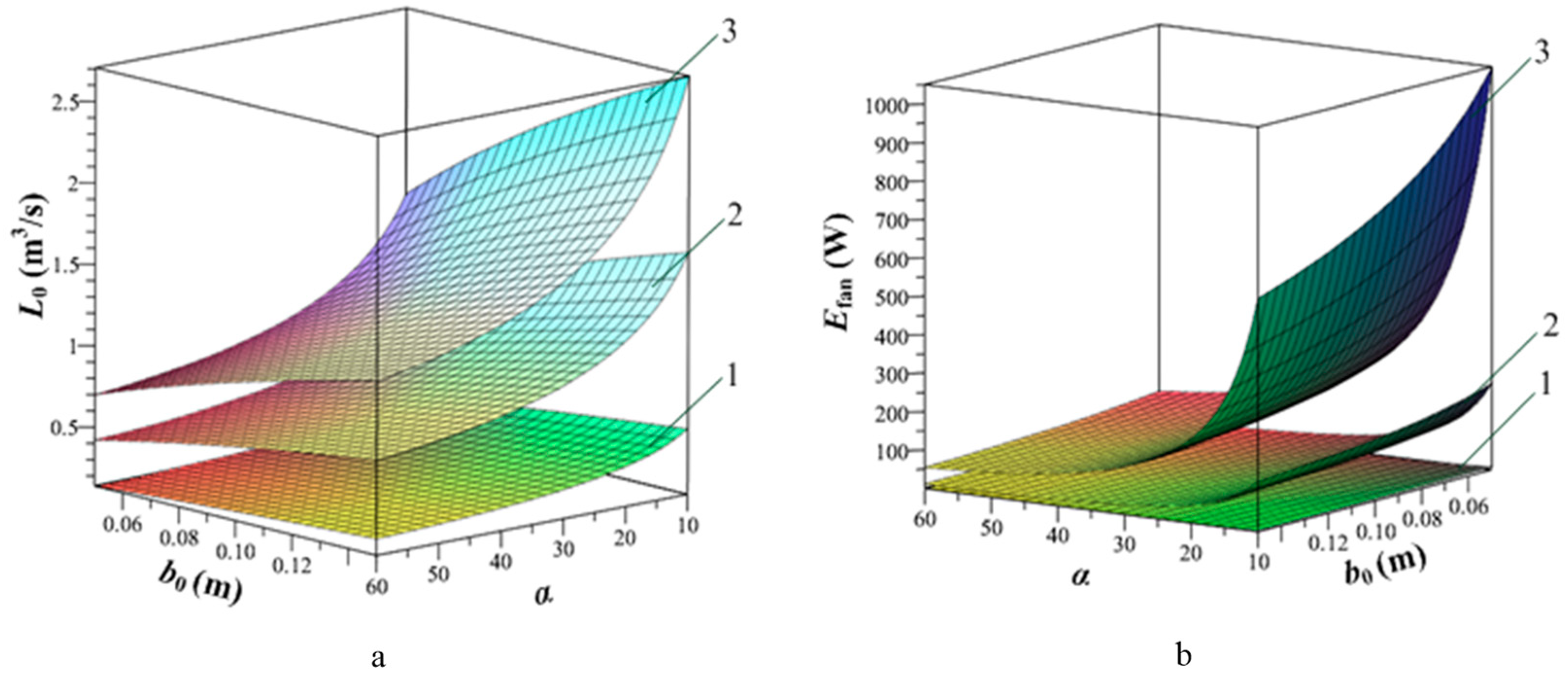
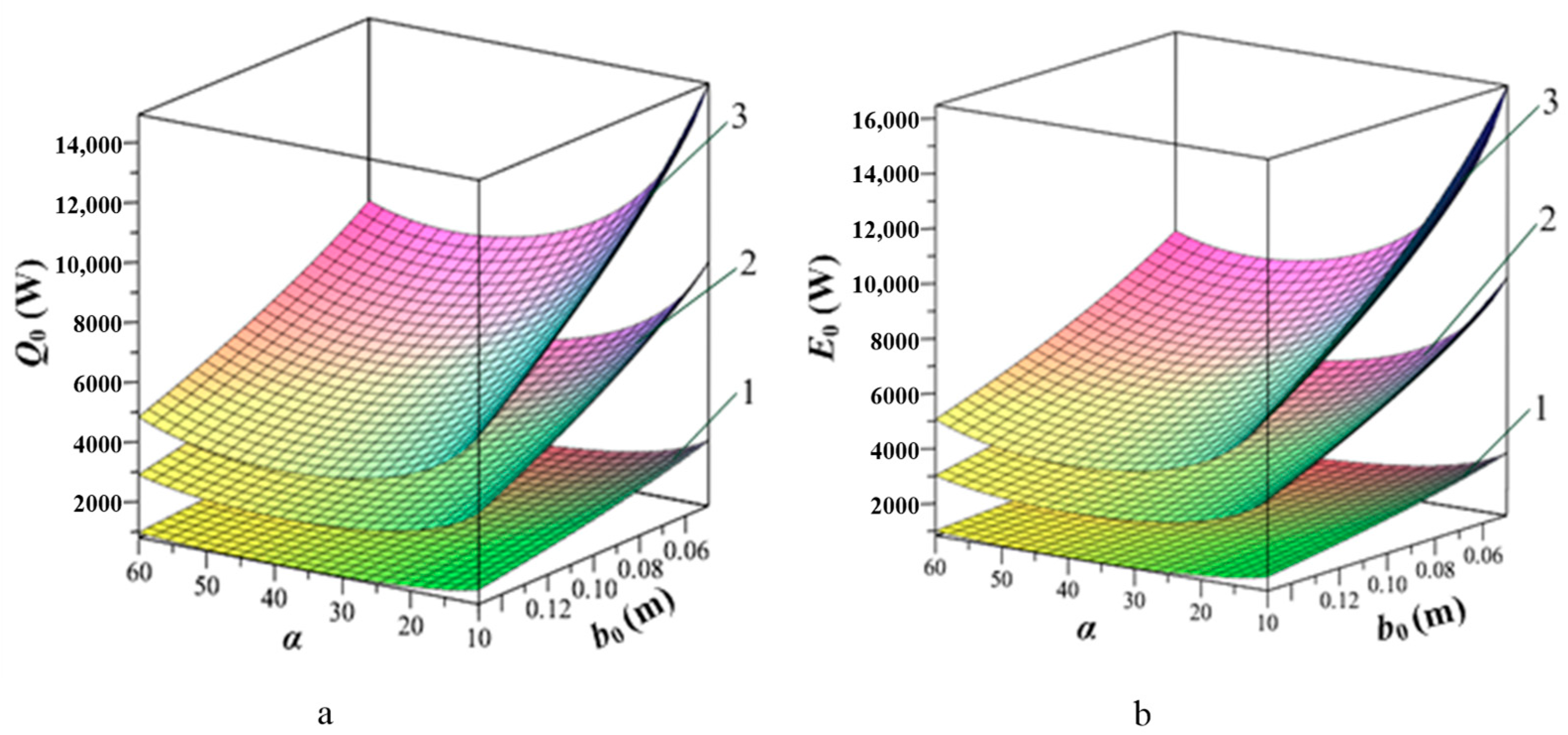
3.3. Calculating the Parameters of the Modular Air Curtain
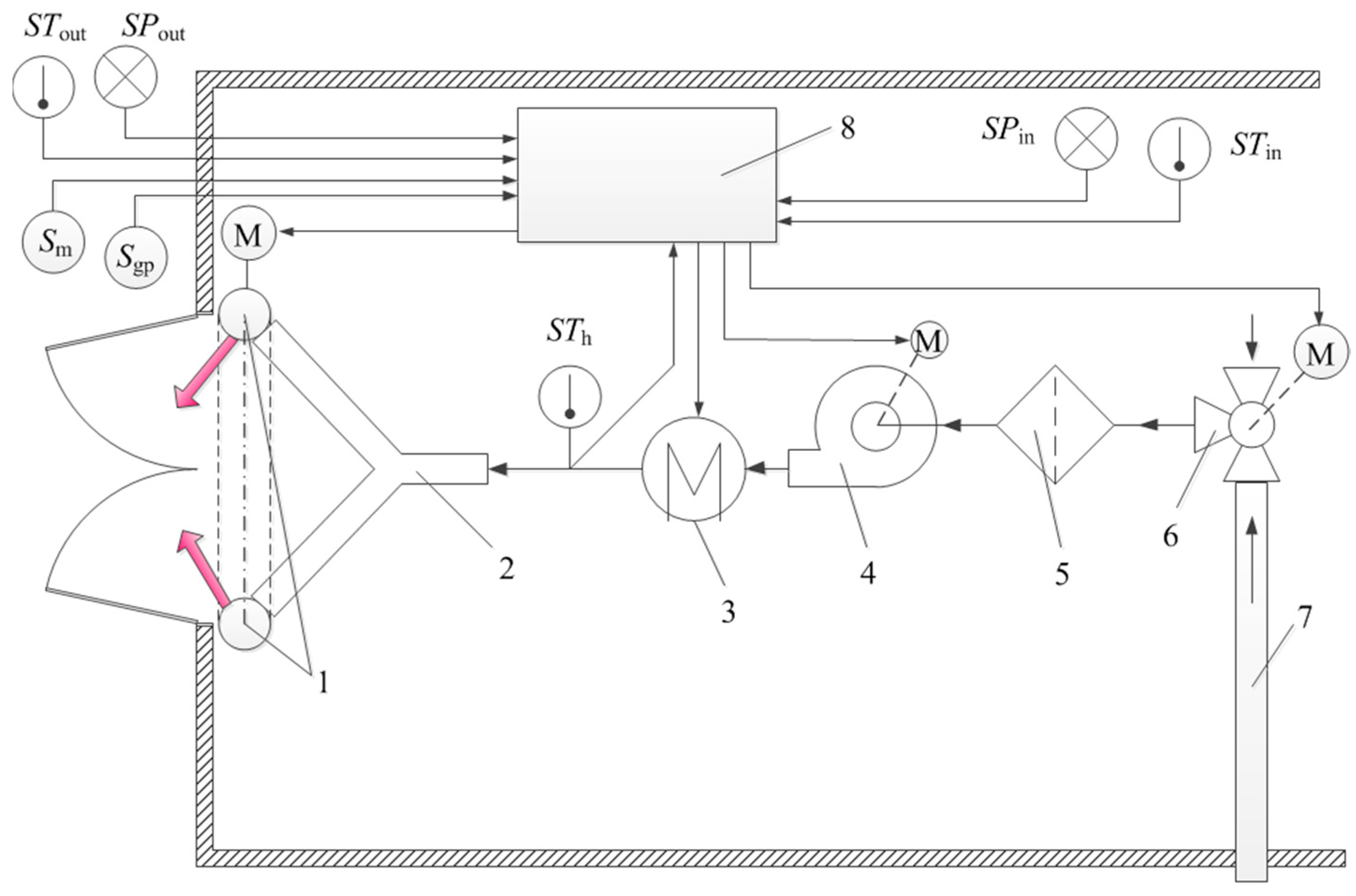
3.4. Block Diagram of the Air Curtain Control System
- -
- Thermal energy characteristics of the air curtain shall be selected depending on the climate parameters of particular regions corresponding to the coldest month conditions (air temperature and wind speed);
- -
- Modular principle of the air curtain structure design;
- -
- Availability of the control functions for the airflow rate and the direction angle of the air jet output from the air curtain slit depending on the wind speed and direction;
- -
- Availability of the air jet temperature control function;
- -
- Heating the air delivered to the air curtain has to be carried out with the use of electric heaters.
4. Conclusions
Author Contributions
Funding
Institutional Review Board Statement
Data Availability Statement
Conflicts of Interest
References
- Tikhomirov, D.; Izmailov, A.; Lobachevsky, Y.; Tikhomirov, A. Energy Consumption Optimization in Agriculture and Development Perspectives. Int. J. Energy Optim. Eng. 2020, 9, 1–19. [Google Scholar] [CrossRef]
- Tikhomirov, D.; Vasiliev, A.; Dudin, S. Energy-Saving Electrical Installations for Heat Supply of Agricultural Objects. In Advanced Agro-Engineering Technologies for Rural Business Development; Kharchenko, V., Vasant, P., Eds.; IGI Global: Hershey, PA, USA, 2019; pp. 96–122. [Google Scholar]
- RD-APK 1.10.01.01-18Methodological Recommendations on Technological Design of Cattle-Breeding Farms and Complexes; Minselkhoz RF: Moscow, Russia, 2018. (In Russian)
- Borshch, O.O.; Borshch, O.V.; Fedorchenko, M.M. Influence of Low Temperatures on Heat Balance in Easily Assembled Premises of Different Types. Ukr. J. Vet. Agric. Sci. 2021, 4, 27–30. [Google Scholar] [CrossRef]
- Borshch, O.O.; Borshch, O.V.; Mashkin, Y.; Malina, V. Behavior and Energy Losses of Cows during the Period of Low Temperatures. Sci. Horiz. 2021, 24, 46–53. [Google Scholar] [CrossRef]
- Borshch, O.O.; Borshch, O.V.; Sobolev, O.I.; Nadtochii, V.M.; Slusar, M.V.; Gutyj, B.V.; Polishchuk, S.A.; Malina, V.V.; Korol, A.P.; Korol-Bezpala, L.P.; et al. Wind Speed in Easily Assembled Premises with Different Design Constructions for Side Curtains in Winter. Ukr. J. Ecol. 2021, 11, 325–328. [Google Scholar]
- Li, Q.; Yao, C.; Ding, L.; Yu, L.; Ma, W.; Gao, R.; Zheng, W. Numerical Investigation on Effects of Side Curtain Opening Behavior on Indoor Climate of Naturally Ventilated Dairy Buildings. Int. J. Agric. Biol. Eng. 2020, 13, 63–72. [Google Scholar] [CrossRef]
- Angrecka, S.; Herbut, P.; Godyń, D.; Vieira, F.M.C.; Zwolenik, M. Dynamics of Microclimate Conditions in Freestall Barns During Winter—A Case Study from Poland. J. Ecol. Eng. 2020, 21, 129–136. [Google Scholar] [CrossRef]
- Hristev, H.; Ivanova, R.; Tasheva, S. A Study of the Farm Factors in Buildings Used for Farming Dairy Cows. Sci. Pap. Ser. D Anim. Sci. 2020, 63, 279–286. [Google Scholar]
- Švajlenka, J.; Kozlovská, M.; Pošiváková, T. Analysis of the Indoor Environment of Agricultural Constructions in the Context of Sustainability. Environ. Monit. Assess. 2019, 191, 489. [Google Scholar] [CrossRef]
- Havelka, Z.; Kunes, R.; Kononets, Y.; Stokes, J.E.; Smutny, L.; Olsan, P.; Kresan, J.; Stehlik, R.; Bartos, P.; Xiao, M.; et al. Technology of Microclimate Regulation in Organic and Energy-Sustainable Livestock Production. Agriculture 2022, 12, 1563. [Google Scholar] [CrossRef]
- Tryhuba, A.; Bashynsky, O.; Hutsol, T.; Rozkosz, A.; Prokopova, O. Justification of Parameters of the Energy Supply System of Agricultural Enterprises with Using Wind Power Installations. E3S Web Conf. 2020, 154, 06001. [Google Scholar] [CrossRef] [Green Version]
- Dorzhiev, S.S.; Bazarova, E.G.; Morenko, K.S. The Features of the Work of Wind-Receiving Devices on Different Speeds of the Wind Flow. In Handbook of Research on Renewable Energy and Electric Resources for Sustainable Rural Development; Kharchenko, V., Vasant, P., Eds.; IGI Global: Hershey, PA, USA, 2018; pp. 383–393. [Google Scholar]
- Dorjiev, S.S.; Bazarova, E.G.; Pimenov, S.V.; Rozenblum, M.I. Development of Wind Power Installations with the Accelerator of an Air Stream for Areas with a Low Speed of Wind. J. Phys. Conf. Ser. 2018, 1111, 012053. [Google Scholar] [CrossRef]
- Khimenko, A.; Tikhomirov, D.; Trunov, S.; Kuzmichev, A.; Bolshev, V.; Shepovalova, O. Electric Heating System with Thermal Storage Units and Ceiling Fans for Cattle-Breeding Farms. Agriculture 2022, 12, 1753. [Google Scholar] [CrossRef]
- Khimenko, A.V.; Tikhomirov, D.A.; Vasilyev, A.N.; Samarin, G.N.; Shepovalova, O.V. Numerical Simulation of the Thermal State and Selecting the Shape of Air Channels in Heat-Storage Cells of Electric-Thermal Storage. Energy Rep. 2022, 8, 1450–1463. [Google Scholar] [CrossRef]
- Khimenko, A.V.; Tikhomirov, D.A.; Kuzmichev, A.V. Experimental Studies of the Thermal Characteristics of Electro-Thermal Storage. IOP Conf. Ser. Earth Environ. Sci. 2021, 839, 052058. [Google Scholar] [CrossRef]
- Tikhomirov, D.; Vasilyev, A.N.; Budnikov, D.; Vasilyev, A.A. Energy-Saving Automated System for Microclimate in Agricultural Premises with Utilization of Ventilation Air. Wirel. Netw. 2020, 26, 4921–4928. [Google Scholar] [CrossRef]
- Trunov, S.S.; Tikhomirov, D.A.; Khimenko, A.V.; Kuzmichev, A.V. Energy-Saving Installation for Heating and Cooling Livestock Premises Using Geothermal Energy. IOP Conf. Ser. Earth Environ. Sci. 2023, 1138, 012043. [Google Scholar] [CrossRef]
- Tikhomirov, D.A.; Trunov, S.S.; Kuzmichev, A.V.; Rastimeshin, S.A.; Shepovalova, O. V Energy-Efficient Thermoelectric Unit for Microclimate Control on Cattlebreeding Premises. Energy Rep. 2020, 6, 293–305. [Google Scholar] [CrossRef]
- Ignatkin, I.; Kazantsev, S.; Shevkun, N.; Skorokhodov, D.; Serov, N.; Alipichev, A.; Panchenko, V. Developing and Testing the Air Cooling System of a Combined Climate Control Unit Used in Pig Farming. Agriculture 2023, 13, 334. [Google Scholar] [CrossRef]
- Kiktev, N.; Lendiel, T.; Vasilenkov, V.; Kapralyuk, O.; Hutsol, T.; Glowacki, S.; Kuboń, M.; Kowalczyk, Z. Automated Microclimate Regulation in Agricultural Facilities Using the Air Curtain System. Sensors 2021, 21, 8182. [Google Scholar] [CrossRef]
- Kim, H.K.; Kang, G.C.; Moon, J.P.; Lee, T.S.; Oh, S.S. Estimation of Thermal Performance and Heat Loss in Plastic Greenhouses with and without Thermal Curtains. Energies 2018, 11, 578. [Google Scholar] [CrossRef] [Green Version]
- Strongin, A.S.; Zhivov, A.M. Energy Efficient Air Curtains for Industrial Gates in Cold Climates. E3S Web Conf. 2021, 246, 08005. [Google Scholar] [CrossRef]
- Tikhomirov, D.A.; Khimenko, A.V.; Trunov, S.S.; Kuzmichev, A.V. Study of the Regularities of the Influence of Air Heat Curtains on the Energy Balance of Livestock Premises. IOP Conf. Ser. Earth Environ. Sci. 2023, 1138, 012044. [Google Scholar] [CrossRef]
- Shelekhov, I.Y.; Dorofeeva, N.L.; Smirnov, E.I.; Shelekhov, M.I.; Dorofeev, I.A. Energy Efficient Methods of Protecting Buildings from Cold Air Flows. IOP Conf. Ser. Earth Environ. Sci. 2020, 880, 012036. [Google Scholar] [CrossRef]
- Andreeva, E.V. Improvement of the Resource-Saving Air-heat Curtain Air Distributor [At the entrances of large industrial premises, warehouses, garages, etc.]. Eng. Tech. Support Agro-Ind. Complex. Abstr. J. 2008, 3, 646. (In Russian) [Google Scholar]
- Johnson, D.A.; Cuaderno, F.R.; Jones, B. Air Curtains as Alternatives to Vestibules. Build. Saf. J. Online 2015, 34–36. [Google Scholar]
- Frank, D.; Linden, P.F. The Effectiveness of an Air Curtain in the Doorway of a Ventilated Building. J. Fluid Mech. 2014, 756, 130–164. [Google Scholar] [CrossRef]
- Frank, D.; Linden, P.F. The Effects of an Opposing Buoyancy Force on the Performance of an Air Curtain in the Doorway of a Building. Energy Build. 2015, 96, 20–29. [Google Scholar] [CrossRef] [Green Version]
- Foster, A.M.; Swain, M.J.; Barrett, R.; D’Agaro, P.; Ketteringham, L.P.; James, S.J. Three-Dimensional Effects of an Air Curtain Used to Restrict Cold Room Infiltration. Appl. Math. Model. 2007, 31, 1109–1123. [Google Scholar] [CrossRef]
- Traboulsi, S.R.; Hammoud, A.; Khalil, M.F. Effects of Jet Inclination Angle and Geometrical Parameters on Air Curtain Performance. ASHRAE Trans. 2009, 115, 617–629. [Google Scholar]
- Kuzmichev, A.V.; Tikhomirov, D.A.; Trunov, S.S. Heat Air Curtains in Microclimate Systems for Livestock Farms. Electr. Technol. Electr. Equip. APK 2019, 1, 14–20. (In Russian) [Google Scholar]
- Kuzmichev, A.V.; Tikhomirov, D.A.; Baklachyan, R.A.; Dobrovolskii, Y.N. The Calculation Methodology and Substantiation of the Technological Scheme of Thermal Curtain. Innov. Agric. 2019, 3, 302–312. (In Russian) [Google Scholar]
- Diskin, M.E. On the Issue of Calculating Air Curtains. AVOC 2003, 7, 58–65. (In Russian) [Google Scholar]
- Rastimeshin, S.A.; Trunov, S.S. Energy-Saving Systems and Technical Means for Heating and Ventilation in Cattle-Breeding Premises; FGBNU VIESH: Moscow, Russia, 2016. (In Russian) [Google Scholar]
- Bogoslovskii, V.N.; Novozhilov, V.I.; Simakov, B.D.; Titov, V.P. Heating and Ventilation (In 2 parts) P. 2. Ventilation; Stroyizdat: Moscow, Russia, 1976. [Google Scholar]
- Baturin, V.V. Fundamentals of Industrial Ventilation; Profizdat: Moscow, Russia, 1990. (In Russian) [Google Scholar]
- Retter, E.I. Architectural-Building Aerodynamics; Stroyizdat: Moscow, Russia, 1984. (In Russian) [Google Scholar]
- Kuzmichev, A.; Tikhomirov, D.; Trunov, S.; Kuzmichev, I.; Lamonov, N. Modular Thermal Air Curtain for Protection of Gate Openings with Variable Vector of Air Jet Direction and Adjustable Width of Slot. Application No. 2019125012, 7 August 2019. RU Patent 2716299 C1, 11 March 2020. (In Russian). [Google Scholar]


Disclaimer/Publisher’s Note: The statements, opinions and data contained in all publications are solely those of the individual author(s) and contributor(s) and not of MDPI and/or the editor(s). MDPI and/or the editor(s) disclaim responsibility for any injury to people or property resulting from any ideas, methods, instructions or products referred to in the content. |
© 2023 by the authors. Licensee MDPI, Basel, Switzerland. This article is an open access article distributed under the terms and conditions of the Creative Commons Attribution (CC BY) license (https://creativecommons.org/licenses/by/4.0/).
Share and Cite
Kuzmichev, A.; Khimenko, A.; Tikhomirov, D.; Budnikov, D.; Jasiński, M.; Bolshev, V.; Ignatkin, I. Study of Potential Application Air Curtains in Livestock Premises at Cattle Management Farms. Agriculture 2023, 13, 1259. https://doi.org/10.3390/agriculture13061259
Kuzmichev A, Khimenko A, Tikhomirov D, Budnikov D, Jasiński M, Bolshev V, Ignatkin I. Study of Potential Application Air Curtains in Livestock Premises at Cattle Management Farms. Agriculture. 2023; 13(6):1259. https://doi.org/10.3390/agriculture13061259
Chicago/Turabian StyleKuzmichev, Aleksey, Aleksei Khimenko, Dmitry Tikhomirov, Dmitry Budnikov, Marek Jasiński, Vadim Bolshev, and Ivan Ignatkin. 2023. "Study of Potential Application Air Curtains in Livestock Premises at Cattle Management Farms" Agriculture 13, no. 6: 1259. https://doi.org/10.3390/agriculture13061259