Article

CFD Simulation and Optimization of the Leaf Collecting Mechanism for the Riding-Type Tea Plucking Machine

1
Zhejiang Academy of Agricultural Machinery, Jinhua 321017, China
2
Zhejiang Province Key Laboratory of Special Purpose Equipment and Advanced Manufacturing, Zhejiang University of Technology, Hangzhou 310023, China
3
Zhejiang Jiu Qi Machinery Co., Ltd., Jinhua 321000, China
*
Author to whom correspondence should be addressed.
Agriculture 2023, 13(5), 946; https://doi.org/10.3390/agriculture13050946
Submission received: 27 March 2023 / Revised: 23 April 2023 / Accepted: 24 April 2023 / Published: 25 April 2023
(This article belongs to the Section Agricultural Technology)

Abstract

:
In the process of tea plucking and leaf gathering, the structure optimization design of the leaf collecting mechanism is the key element responsible for collecting fresh leaves. The unreasonable design and manufacture of leaf collecting mechanisms will cause the smooth collection of fresh leaves, the quality of the collected fresh leaves will be damaged, and the commodity value will be reduced. In order to further study the structural characteristics of the leaf collecting mechanism, an air outlet model of the leaf collecting mechanism was established for the phenomena of internal vortex rotation and impact in the leaf collecting mechanism process. The internal flow field of the leaf collecting mechanism, the movement trajectory of fresh leaves, and the non-homogeneous flow are calculated using computational fluid dynamics (CFD). Based on Box-Behnken’s central combinatorial design theory, the velocity inlet and outlet air structure factors are taken as the influencing factors to carry out response surface test research. The effect of different parameters such as engine rotation, shape of the blowing cavity and air outlet parts, and velocity on the flow is determined. The optimal parameter combination is as follows: the height of the outlet end, the length of the inlet end, and the velocity inlet are 0.01 m, 0.03 m, and 25 m/s, respectively. Furthermore, it was found that when the number of plates increases from 1 to 4, the non-homogeneity decreases all the time, and the distribution of blowing air is improved without a sharp decrease in velocity. The average velocity outlet was larger than the velocity inlet, which meets the requirements of blade gathering. Considering comprehensively, the flow field simulation of the blade collecting mechanism with four baffles was consistent with the test results of the velocity outlet. The validation results showed that the model can successfully simulate the air flow inside the leaf-collecting mechanism, and the reasonable structure design was conducive to reducing the number of collisions between tea buds and improving the quality of tea buds. This research has certain theoretical and practical implications for the accurate plucking of high-quality tea.

1. Introduction

Tea, made from the leaves of Camellia sinensis, is the most popular beverage in the world, second only to water, and mainly produced in China, India, Kenya, and Sri Lanka [1,2]. In 2019, the annual tea production of the above countries was close to five million tons, and the annual value of tea agricultural production exceeded nine billion dollars [3]. Tea leaves are plucked by hand or using a machine [4]. Hand plucking prevents broken leaves and ensures that only the most essentially favorable parts are plucked [5,6,7].
However, a labor shortage has caused the tea industry to shrink. Conventional tea harvesting by hand is labor-intensive. Among the tea-growing countries, Japan, England, France, India, Australia, and Argentina have all realized mechanization of tea harvesting, respectively. However, tea harvesting in China just stands at a semi-mechanized state level. Therefore, plucking machines are used to boost the harvest efficiency of tea leaves. Among the many kinds of plucking machines, riding-type machines have the highest efficiency of approximately 4000–5000 kg/person a day [8,9,10]. Lin et al. [8] develop a guiding and growth status monitoring system for riding-type tea plucking machines using fully convolutional networks.
As collecting fresh leaves is the most initial step in the tea industry chain, it has a particularly critical impact on the yield and quality of fresh leaves. The quality of the tea can be judged from its appearance because the quality of the tea is directly related to the fresh leaves from which it was picked. If the breakage rate of buds and leaves is higher, the quality of fresh tea is judged to be lower; conversely, the more intact the leaves are, the higher the quality is. To prosper in its tea industry, it is necessary for China to improve its mechanization level of tea plucking, not only by researching, designing, and producing but also by popularizing it [10]. The leaf collecting mechanism, as a key part of the tea plucking machine, functions to act on the air volume generated by the fan on the fresh leaves cut from the tea leaf surface and then send the fresh leaves into the leaf collecting mechanism on the vehicle. Whether fresh leaves can be collected successfully depends on the outlet flow velocity of the branch pipe of the ventilation pipeline. If the velocity is too small, fresh leaves cannot be sent to the leaf collecting mechanism. If the velocity is too large, the branch pipe outlet air field is not stable, which is easy to make tea buds shake, seriously affects the quality of fresh leaves. Additionally, the operation power is too large, preventing energy savings and environmental protection.
A reasonable leaf collecting mechanism can improve the transport ability of the cut, fresh leaves to the collecting bag. Therefore, through the analysis of the internal flow field of the air outlet parts and the related research on the uniformity of branch pipe velocity, the corresponding improvement of the parts mechanisms can effectively ensure the quality of tea harvesting.
Computational fluid dynamics (CFD) has recently found increasing applications in the chemical industry, biomedical industry, and food industry [11,12,13]. The present study is the first attempt to simulate heat transfer and polyphenol oxidation during tea fermentation [14]. A three-dimensional transient CFD study was performed to investigate the hydrodynamic characteristics of the teabag motion in a cup during tea infusion [15,16]. In recent years, scholars have used CFD to simulate multi-phase flow. Through the analysis of flow field characteristics, complex structures can be optimized. Therefore, the method is applied to the structure research of tea picking machines [17,18,19,20]. Machine-picked fresh leaves belong to the flexible sheet material, which has the characteristics of complex force and nonlinear deformation. The numerical calculation of its movement characteristics is the difficulty of computer numerical simulation. The gas-solid two-phase flow of flexible materials is the technical bottleneck in the development of agricultural machinery and equipment. The leaf gathering process of a riding-type tea plucking machine was numerically simulated to understand the air flow distribution and form the basic theory of gas-solid two-phase coupling oriented to flexible sheet fresh leaves, which provided the technical basis for the development and optimization of mechanical equipment for tea picking.
In this study, a riding-type tea plucking machine is taken as the research object. Compared with other single-person tea plucking machines and two-person tea plucking machines, the riding-type tea plucking machine reduces manpower, improves the working environment, and greatly improves the efficiency of tea plucking. The general tea plucking machine uses a curved pipe air supply to collect tea buds, while this type of riding-type tea plucking machine adopts a leaf collecting mechanism to do so. Extending the single tuyere of the fan to the whole width of the tea canopy through the appropriate structure and the air out of the uniform effect is the key. The flow field analysis of the leaf collecting mechanism is helpful to the structural design and function realization of the equipment.

2. Materials and Methods

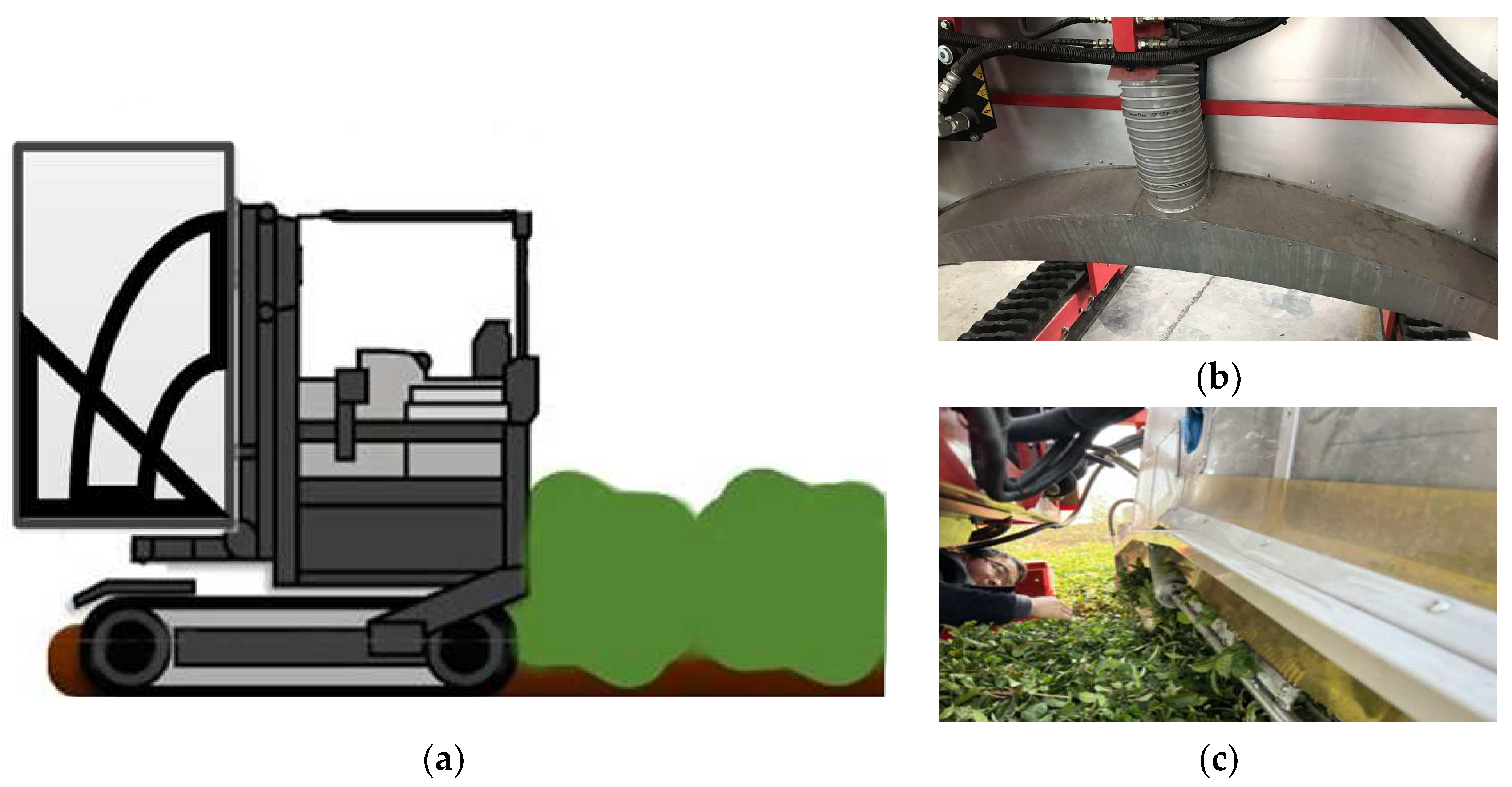
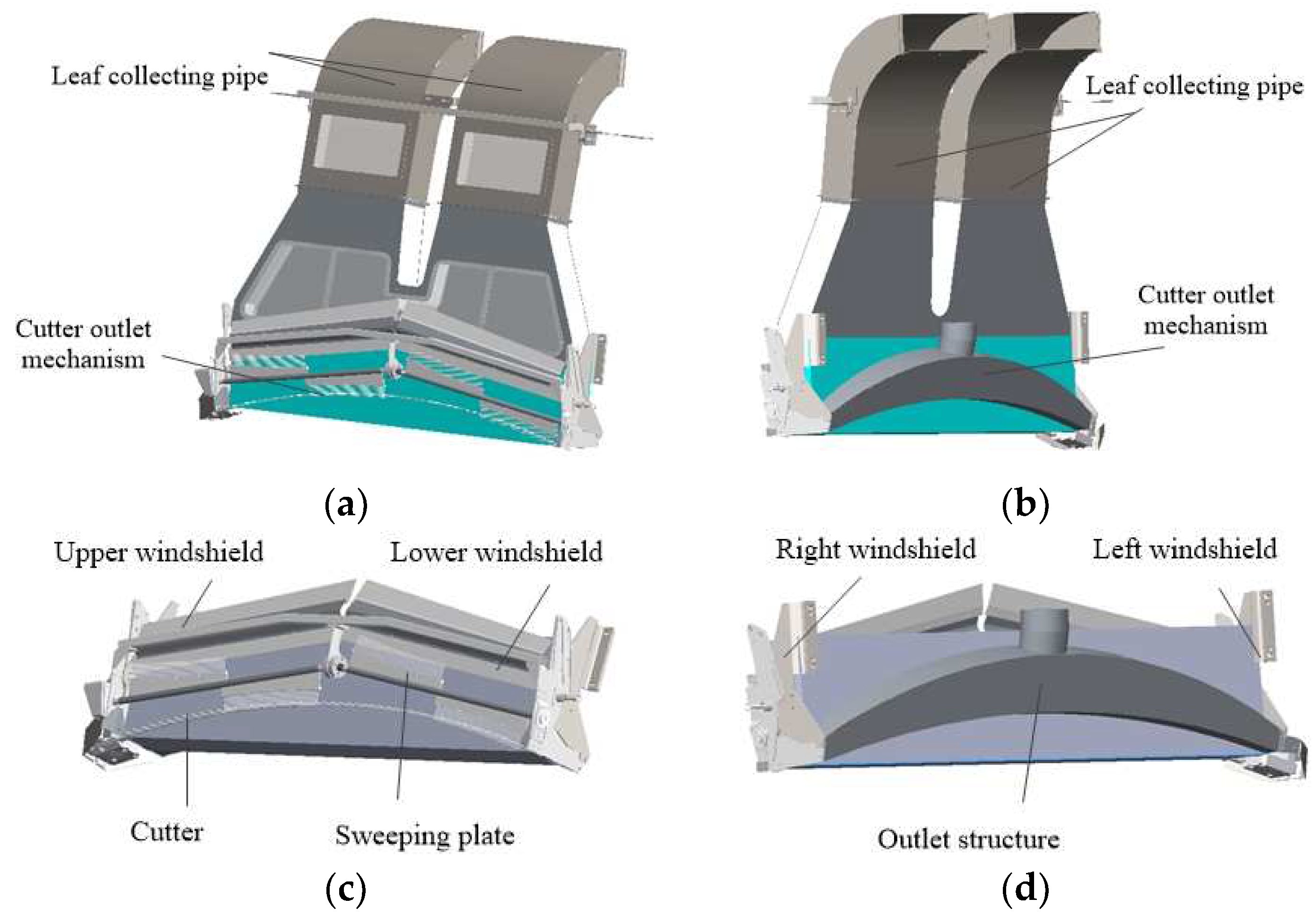
2.1. Overall Structure of Tea Plucking Machine

The riding-type tea plucking machine is composed of main mechanisms such as the plucking mechanism, leaf collecting mechanism, regulating mechanism, and walking mechanism, as shown in Table 1 and Figure 1. The whole equipment is controlled by a hydraulic system, and the bottom is a rubber crawler-type hydraulic chassis to realize cross-line walking. A tea cutting device is arranged on the rack, and the cutting posture is consistent with the tea shape in real time. With the track driven by a hydraulic system, it could travel flexibly in complex tea gardens. While traveling along the tea rows, it rides on the tea trees (two tracks on the other side of the trees), and the cutter moves on the top of the tea crown. Except for moving forward, the cutter has another reciprocating motion of its two blades, which cut the tea leaf off directly. So, the operation principle of the tea plucking machine is to use the upper and lower serrated knives to repeatedly cut the fresh leaves on the tea tree and send them to the leaf collecting box (bag) on the car through a certain airflow. A cutting table for the tea machine is arranged between the cutting mechanism and the collection box (bag). Its structure plays an important role. The use of an effective air supply can make sure that the tea is not damaged and that the quality of plucking fresh leaves is maintained.

2.2. Mathematical Model

The fluid studied in this paper is air. It is assumed that its viscosity does not change with the change of temperature when moving in the leaf collecting mechanism, so it is regarded as an incompressible fluid. According to the riding-type tea plucking machine, the outlet velocity of the airflow flow field in the leaf collecting mechanism must be greater than 10 m/s.
According to the calculation of fluid Reynolds number in a non-circular tube, it is known that the Reynolds number of the flow field of the blade collecting mechanism is Re = 137,886, which is much larger than the critical Reynolds number in engineering applications (Re > 4000 is the turbulent state), so the flow field belongs to the turbulent model.
R e = ρ v D H μ
D H = 4 A P
where v (m/s) is the average flow velocity, ρ (kg/m3) is the fluid density, μ (Pa·s) is viscosity, DH is equivalent diameter, A is the area of the flow section, and P is the wetted perimeter.
Turbulence is a structured flow with strong dispersive, disordered, and dissipative properties. From the perspective of structure analysis, turbulence is a flow formed by the interaction of rotating vortices of different intensities and scales, and its size and steering are random and unsteady. In order to study the influence of ray flow pulsation, the time average of the mean normal field variable φ is defined as:
φ ¯ = 1 Δ τ τ τ + Δ τ φ ( τ ) d τ
The mean quantity φ ¯ and pulsation quantity φ represents the instantaneous random value of the field variable, which is decomposed into
φ = φ ¯ + φ
The sum of the average value and pulsation value is used to represent the flow variable as follows:
u = u ¯ + u u = u ¯ + u v = v ¯ + v w = w ¯ + w p = p ¯ + p
The governing equation of the time-mean flow of the Rayleigh flow is:
div u ¯ = 0
u ¯ t + div ( u ¯ u ¯ ) = 1 ρ p ¯ x + v div ( grad u ¯ ) + [ u 2 ¯ x u v ¯ y u w ¯ z ]
v ¯ t + div ( u ¯ u ¯ ) = 1 ρ p ¯ y + v div ( grad v ¯ ) + [ u v ¯ x v 2 ¯ y v w ¯ z ]
w ¯ t + div ( w ¯ u ¯ ) = 1 ρ p ¯ z + v div ( grad w ¯ ) + [ u w ¯ x v w ¯ y w 2 ¯ z ]
The transport equations of the other variables can be treated similarly, and obtained as follows:
φ ¯ t + div ( φ ¯ u ¯ ) = div ( Γ grad φ ¯ ) + [ u φ ¯ x v φ ¯ y w φ ¯ z ] + S
In actual flow, the governing equation of compressible fluid flow can be obtained by considering only the change in average density. For convenience, except for the mean value of the pulsation value, the upper line denoting the mean value of the time is removed in the following equation:
Continuity   equation :   ρ τ + div ( ρ u ) = 0
N-S equation:
The mass conservation equation and energy conservation equation laws are followed in the study of the flow field of the collector blade mechanism. Because the L-VEL and yPlus algebraic turbulence models calculate turbulent viscosity based only on the local velocity and distance from the nearest wall. The k-ε model is very effective for solving the problem of external flow around complex geometry. Additionally, the change in heat and energy conservation equation is not considered; the standard k-ε model can be used for the turbulent motion equation. The k-ε turbulence model assumes that the flow is completely turbulent and the effects of molecular viscosity are negligible. Based on the equation of Rayleigh kinetic energy, the equation of Rayleigh dissipation rate is introduced:
k = u i u j ¯ 2
ε = μ ρ ( u i x k ) ( u j x k ) ¯
The k-ε turbulence model is a turbulence model proposed by Jones and Launder [21]. It mainly determines the turbulence viscosity coefficient by solving two additional equations: the k equation (k is turbulence kinetic energy) and ε equation (Epsilon, dissipation rate of turbulence kinetic energy), and then solves the turbulence stress. When the standard k-ε model is used to solve the real turbulence problem, the governing equations include the continuity equation, momentum equation, energy equation, k-ε equation, and viscosity coefficient equation [22]. Suppose that the components of a fluid element per unit mass on each coordinate axis are denoted as x, y, and z, respectively:
ρ k t + ρ u j k x j = x j [ ( μ + μ t σ k ) k x j ] + μ t u i x j ( u i x j + u j x i ) ρ ε
ρ ε t + ρ u k k x k = x k [ ( μ + μ t σ ε ) ε x k ] b 2 4 a c + c 1 ε k μ t u i x j ( u i x j + u j x i ) c 2 ρ ε 2 k
μ t = c μ ρ k 1 2 l = ( c μ c D ) ρ k 2 1 c D k 3 2 / l = c μ ρ k 2 / ε
c μ = c μ c D c μ = c μ c D
where k (J) is turbulent kinetic energy, ε (%) is the dissipation rate of turbulent kinetic energy, t is the time variable, l (m) is the turbulence length scale. According to the empirical formula, k = 3/2(uavgI)2, where uavg (m/s) is the average fluid velocity, I is turbulence intensity, ε = C μ 3 / 4 k 3 / 2 / l . The three coefficients c1, c2, and cμ and the three constants σk, σε, and σt are generally 1.44, 1.92, and 0.09 and 1.0, 1.3, and 0.9–1.0, respectively.

2.3. Numerical Calculation

The SOLIDWORKS geometric model of the leaf plucking mechanism was established. The model of the air outlet part of the riding-type tea plucking machine was meshed, and a reasonable turbulence model and solving parameters were selected. The three-dimensional numerical simulation [23,24] of the internal flow field of the air outlet part of the riding-type tea plucking machine was carried out. Through flow field analysis, the structure of the air outlet component is optimized. The simulation results of the optimized structure are compared with the test results of the uniformity of the velocity outlet. The feasibility of numerical simulation of a three-dimensional wind component model is verified. The optimization of the air outlet part improves the overall tea plucking efficiency of riding-type tea plucking machines.

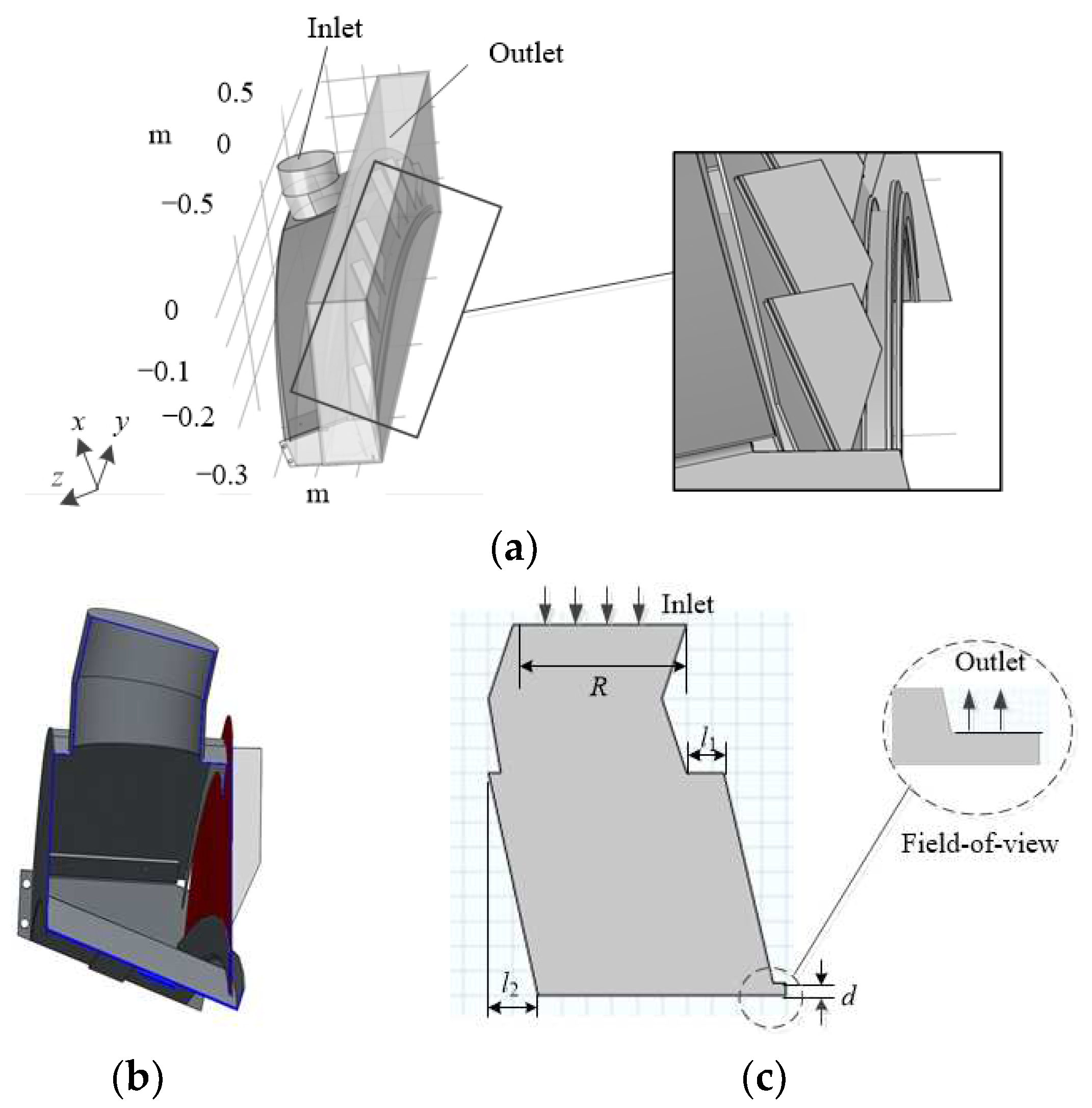
2.3.1. The Physical Model

In order to ensure that the simulation analysis results are consistent with the actual testing, the feasibility of the flow field analysis process of the air outlet part of the riding-type tea plucking machine is measured so as to facilitate the optimization and improvement of the internal structure of the air outlet part. Therefore, before simulating the physical model, the following assumptions should be made:
  • According to the working environment requirements of the air outlet part of the riding-type tea plucking machine in the tea garden, the working medium of the fluid is air, which belongs to the Newtonian flow type of fluid. It is assumed that the density and viscosity of the air are unchanged at the pressure of 102,325 Pa and the temperature of 26.85°, which is a certain value. The air density is 1.16 kg/m3. It is assumed that the working medium is a continuous, incompressible, viscous fluid when the fluid is flowing;
  • Each part of the air outlet part is an absolute rigid body, and it will not deform when working. The interaction between the inner wall of the air outlet part and the working medium is ignored when the fluid flows;
  • When tea is collected by outlet air, it is assumed that the air flow generated by the fan has a uniform air velocity, and the velocity inlet in the flow field area is kept constant in the simulation analysis. The air enters with constant velocity and ignores the heat exchange when the working medium air flows inside the air outlet component. That is, in the process of three-dimensional numerical simulation, the energy equation is not considered, but only the pressure field and velocity field of the flow field are solved;
  • Due to manufacturing errors, there may be a very small amount of air leakage in the air outlet parts of riding-type tea plucking machines. However, when conducting numerical simulation, the model can be simplified as far as possible, or it can be in an ideal state, and the very small part of air leakage can be ignored.
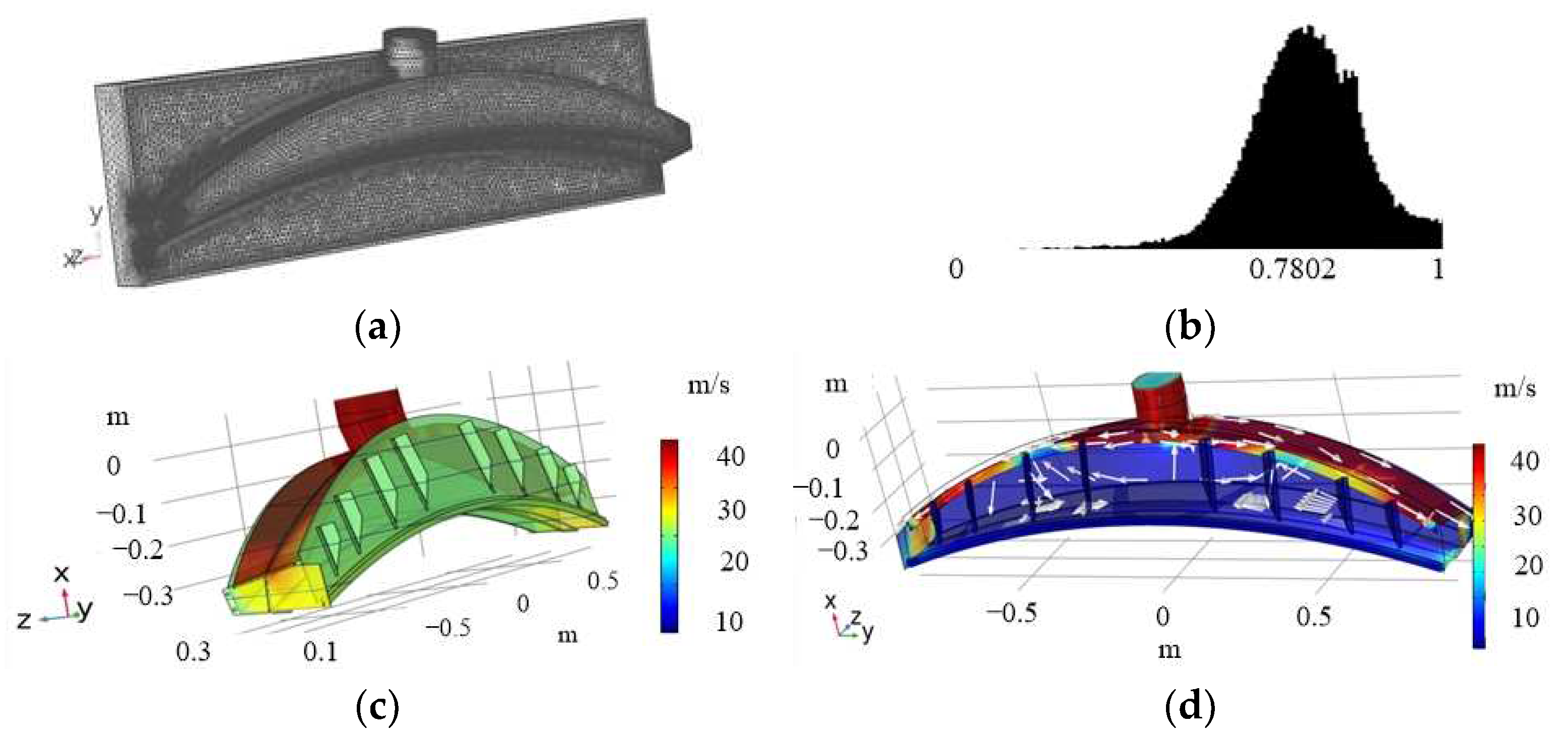
In this paper, the cutting table and leaf collecting mechanism of the riding-type tea plucking machine are taken as models, and their mapping and modeling are carried out (shown in Figure 2). All materials are made of stainless steel. The air volume at the inlet is provided by a medium-pressure fan with a velocity of 7500 rpm. When establishing the model, it is necessary to make the axis of one air inlet and outlet in a plane, simplify the contact between the end of the air inlet and the main air outlet components, and place them horizontally.

2.3.2. Meshing

The SOLIDWORKS software is used to establish the physical model of the air component, as shown in Figure 3a. The air outlet area model is designed according to the actual tea row width and shape characteristics of curves. According to the relevant data of the gentle slope tea garden, in southern tea gardens, the tea tree form is generally 800~900 mm in the height of the tea shed, 1200 mm in the width of the tea rows, and 600 mm in the width between the tea rows. The tea leaves are usually grown on the curved surface with a vertical height of 150 mm. According to the law of tea growth, the tea canopy is built into a certain curvature, which is helpful for tea plucking. The shape and design of the air outlet are consistent with those of the tea tree.
Figure 3a shows the air outlet structure of the simulation object, and the air inlet is a cylindrical pipe that is connected with the fan. The air outlet is the upper and lower sides of the cuboid (drawing the cuboid for simulating the airflow field). According to the geometric model of the air outlet parts, the air inlet and outlet are divided into grids by regions. That is, the air inlet and outlet are divided into structured hexahedral grids, and the main air outlet parts are divided into unstructured tetrahedral grids. The boundary layer at the outlet is created for local mesh encryption processing. The total number of grids is 599,122 (Figure 4a), and the average unit mass is 0.7802 (Figure 4b). The closer the value is to 1 and the overall quality histogram is to the right, the better the grid quality is. So, the grid quality meets the requirements.

2.3.3. The Boundary Conditions

In the numerical simulation analysis of the air outlet components, the influence caused by heat exchange is ignored. That is, the energy equation is not considered; it belongs to turbulent flow, and the working medium is air. There is no phase transition, chemical composition, or chemical reaction in the calculation process. The simulated values are solved based on the pressure separation implicit solver. In order to improve the calculation accuracy, the second-order upwind discrete scheme and SIMPLEC algorithm are used [25]. The working environment is set up as one standard atmosphere. Table 2 lists the boundary condition settings used for the simulation.

3. Results

3.1. Air Outlet Mechanism Model

In order to reasonably design the air outlet parts of a riding-type tea plucking machine in a tea garden and improve the efficiency of leaf collection, the shape of the tea tree after construction should be considered. Considering the actual production and operating conditions, the influence of the velocity inlet, cavity structure, and baffle structure on the leaf gathering effect is further studied.

3.1.1. Air Outlet Cavity Structure

Figure 4 shows the flow field in the cavity of the air outlet part. When the fan air flows from the upper end of the air outlet part and guides the air into the main air outlet cavity, the turbulence intensity is not strong. Due to its structural characteristics, part of the air flow moves radially perpendicular to the cavity, and the other part moves parallel to the cavity. When the air flow is near the bottom of the air outlet cavity, part of the air flow bounces back to the interior of the air outlet chamber and forms a mixed air flow with the upper air flow. The strong collision between the fluids makes the flow field in the cavity complex and forms an eddy current. In addition, the turbulence intensity in the eddy current area increases, especially in the cross-section area, resulting in local resistance loss in the cavity. The other part, according to Bernoulli’s equation, flows out through the gap of the outlet.
Due to the narrow section of the air outlet part, the air flow area changes abruptly, resulting in the contraction of the flow strand and a sudden increase in the turbulence intensity of the air flow rate. However, it will lead to unstable air flow and an uneven distribution of the velocity outlet. According to the interface diagram of the blowing cavity (shown in Figure 3b,c), the wind enters the inner cavity from the upper inlet, fills the whole cavity, and blows out from the right outlet. The structural dimensions are: d = 0.01 m, l1 = 0.03 m, l2 = 0 m, and R = 0.14 m. The flow field in the cavity is simulated when the velocity inlet is accelerated at 25 m/s. As shown in Figure 5, due to the cavity structure, the velocity outlet is significantly greater than the inlet velocity. At different velocity inlets, the velocity outlet when d is 0.01 m is greater than that when d is 0.02 m and 0.03 m (shown in Figure 5a,b). However, when l1 at the inlet is 0.01 m, 0.03 m, or 0.05 m, the change of velocity outlet is similar (shown in Figure 5c,d). Figure 5e,f shows that no matter the value of the inlet velocity, the change trend of the velocity outlet is similar when l2 is 0 m, 0.01 m, and 0.02 m, respectively. However, when R is 0.14 m, the velocity outlet is generally larger than that of 0.10 m and 0.12 m (shown in Figure 5g,h). Comparing Figure 5a with Figure 5g, when R is smaller, the eddy current area of the left flow field is larger, and the flow field is more disordered, which affects the flow velocity. To sum up, the values of d, R, and v have a great influence on the velocity outlet, while the other two factors have no obvious influence.

3.1.2. Air Outlet Baffle Structure

As shown in Figure 6a, the tea canopy surface is trimmed by the machine cutting table so that the circular arc cutter is cut with the tea canopy surface. The air outlet plate is divided into nine areas; the width of each area is not the same, and the distance between the two sides is symmetrical. The narrowest area on the outside is 120 mm, and the widest area in the middle is 437 mm. Three test points (Figure 6b) are set, respectively, in the nine areas of the air outlet plate, and then the average value is taken as the velocity value of this area. According to the analysis of the above model results, the air flow enters through the air inlet, flows out of the air outlet under the action of the flow field in the cavity, and then passes through the baffle partition of the air plate. The velocity inlet accelerates from 13 m/s to 25 m/s, and the velocity change law of each region is consistent (shown in Figure 7). The greater the velocity inlet, the greater the velocity outlet, and the velocity of the outermost region on the left and right sides is greater than that of the inner seven regions, and the difference between the middle velocity is not significant. This is because the two ends of the inner cavity of the air outlet structure are narrow and the middle is wide. After that, the air flow is divided through the air outlet plate, and the area on both sides is narrower than the middle. The simulation results show that the velocity outlet is above 10 m/s. Therefore, the air outlet part disperses the air flow to each area, and the velocity outlet meets the leaf collection effect.

3.2. Optimization of the Air Outlet Mechanism

In the process of tea plucking and leaf gathering, the principle is to maximize the velocity outlet and stabilize the flow field. However, it is difficult to find the optimal solution due to the difference in the degree of influence of parameters such as velocity outlet, baffle spacing, and baffle number on the mechanical properties of the internal flow field. In this paper, by changing some technical parameters to the internal flow field of the corresponding simulation and comparative analysis, the air velocity is changed so as to optimize the air outlet mechanism.

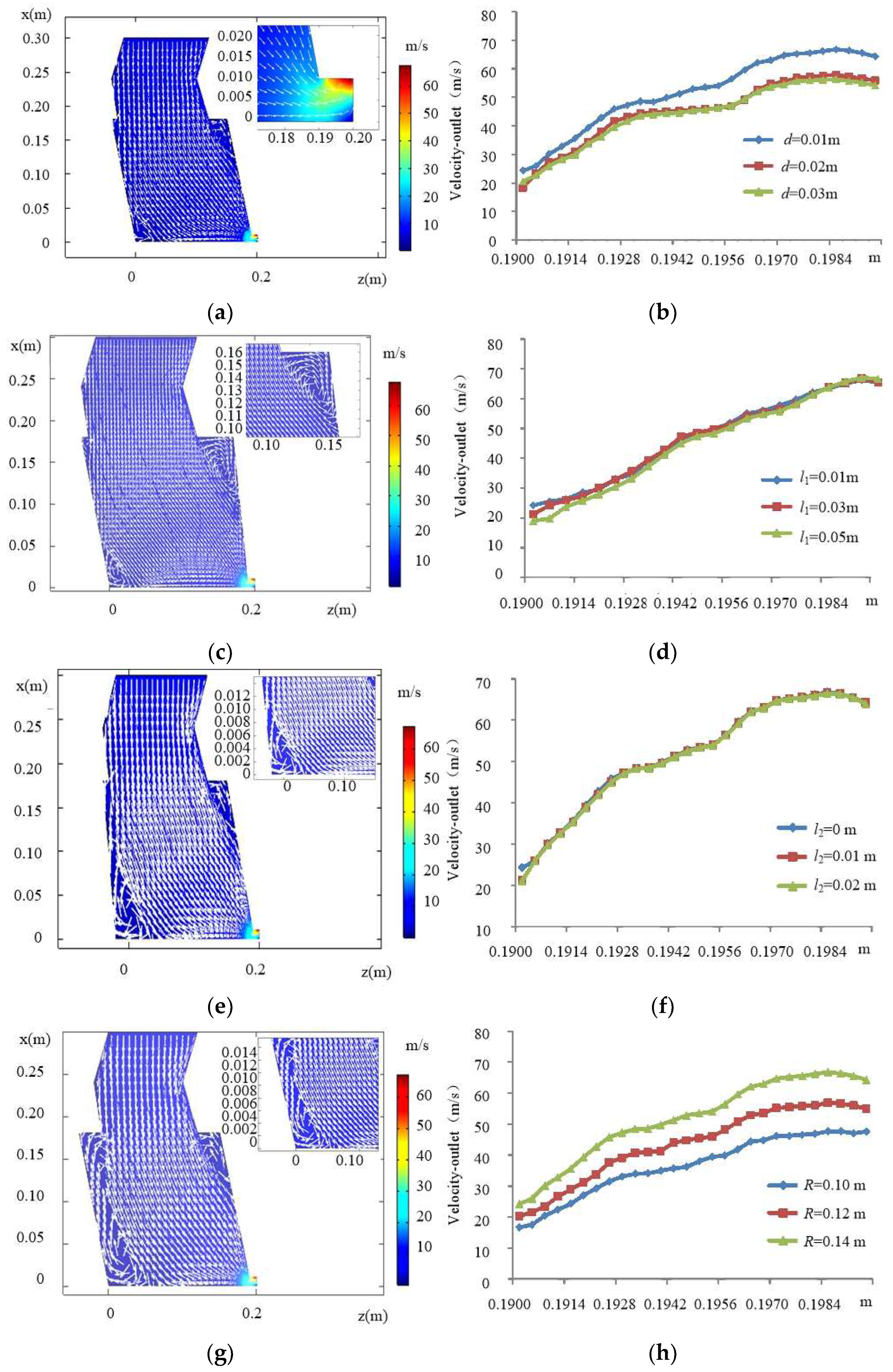
3.2.1. Optimization of the Cavity Structure

In order to optimize the cavity structure, the gas-solid coupling simulation method is used to carry out orthogonal experiments [26], which take d, ll, l2, R, and velocity inlet as test factors. The design of orthogonal test factors is shown in Table 3. The above simulation results show that the distribution of velocity outlet is consistent under different conditions, and the midpoint is taken as the observation point of velocity outlet.
In order to obtain the optimal parameter combination, a five-factor, three-level analysis test was designed according to the Box–Behnken test principle [27], which uses multiple quadratic equations to fit the functional relationship between factors and effect values, and seeks the optimal process parameters through the analysis of regression equations to solve the multi-variable problem, including a total of 46 groups of tests. The test scheme and results are shown in Table 4, with X1, X2, X3, X4, and X5 as the coding values.
The model F-value of 88.26 implies the model is significant in Table 5. There is only a 0.01% chance that an F-value this large could occur due to noise. p-values less than 0.0500 indicate that model terms are significant. In this case, X1, X4, X5, X1X4, X3X4, X4X5, and X12 are significant model terms. Values greater than 0.1000 indicate the model terms are not significant. If there are many insignificant model terms (not counting those required to support hierarchy), model reduction may improve this model. A multiple regression fitting analysis was carried out to establish the response surface regression model of Y to X1, X2, X3, X4, X5, and an analysis of variance was performed on the regression equation. The response surface regression model of Y to X1, X2, X3, X4, and X5 is
Y = 29.92 2.05 X 1 0.307 X 2 0.3363 X 3 + 4.48 X 4 + 9.68 X 5 + 0.1518 X 1 X 2 0.0988 X 1 X 3 1.7 X 1 X 4 0.7428 X 1 X 5 0.0575 X 2 X 3 + 0.0097 X 2 X 4 0.098 X 2 X 5 1.25 X 3 X 4 + 0.0047 X 3 X 5 + 1.57 X 4 X 5 + 2.64 X 1 2 0.0482 X 2 2 0.2966 X 3 2 + 0.0575 X 4 2 + 0.1385 X 5 2
In the constraint optimization solution module, the optimal parameter combination for the maximum velocity outlet Y satisfying the constraint conditions can be obtained. Figure 8 shows the scatter plot of the actual value and the predicted value of the visualized regression model. It can also be seen that d, R, and v are the most significant factors affecting the velocity outlet. A comprehensive analysis of the influence relationship and degree of test factors on the index can be found, as can the corresponding impact of velocity outlet under a single factor change. When d increases, the velocity outlet first decreases and then increases. When the inlet radius increases, the velocity outlet also increases. When the velocity inlet increases, the velocity outlet increases, obviously. However, the change in length of the upper and the bottom length has little effect on the velocity outlet. The optimal parameter combination is as follows: height of the outlet end X1, length of the upper X2, bottom length X3, inlet end radius X4, and velocity inlet X5 are 0.01 m, 0.03 m, 0 m, 0.14 m, and 25 m/s, respectively. The corresponding velocity outlet is 53.348 m/s.

3.2.2. Optimization of the Baffle Structure
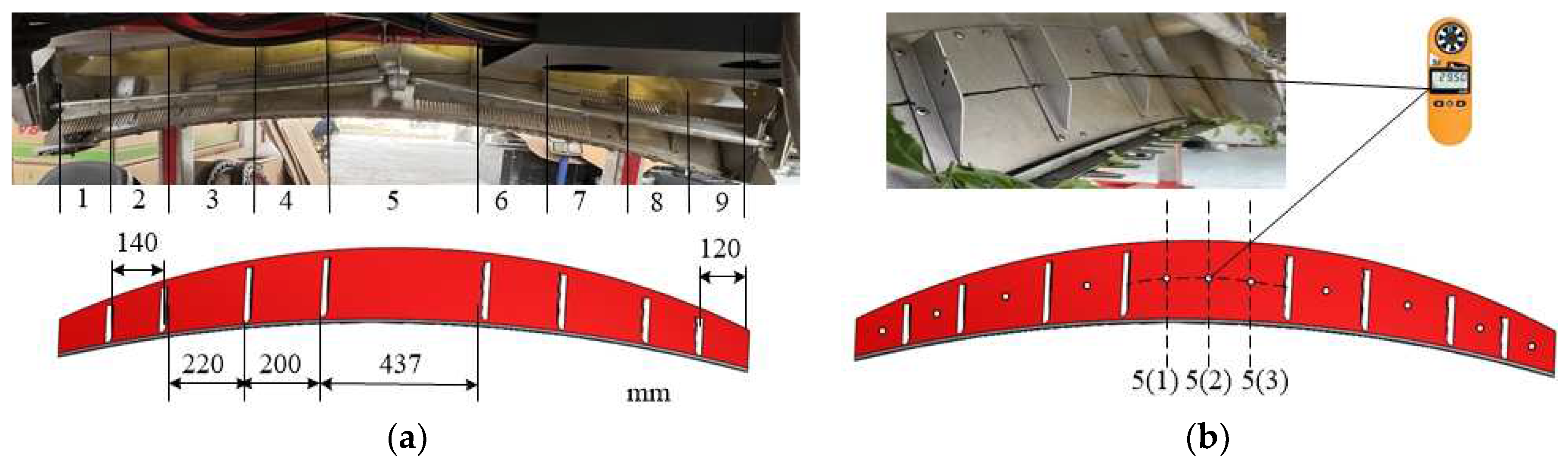
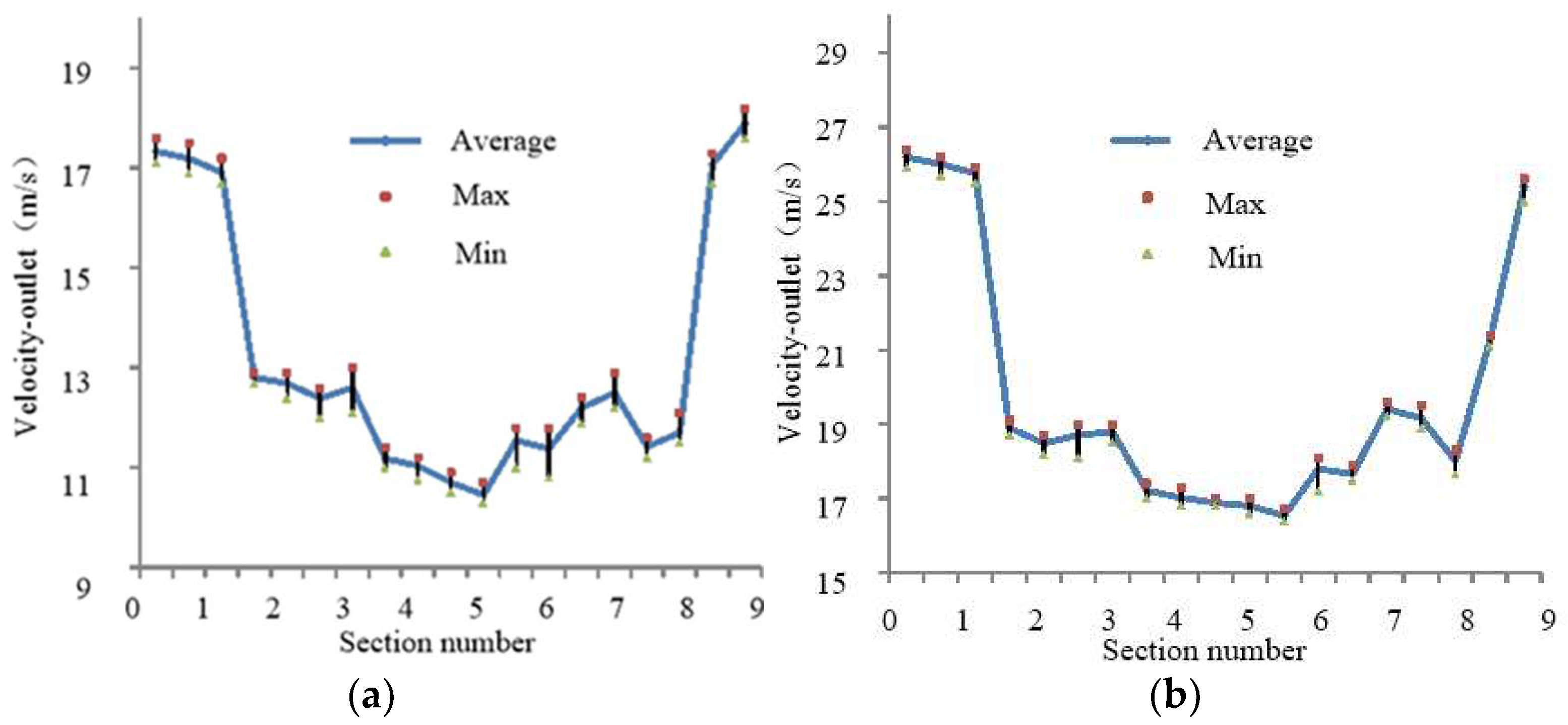
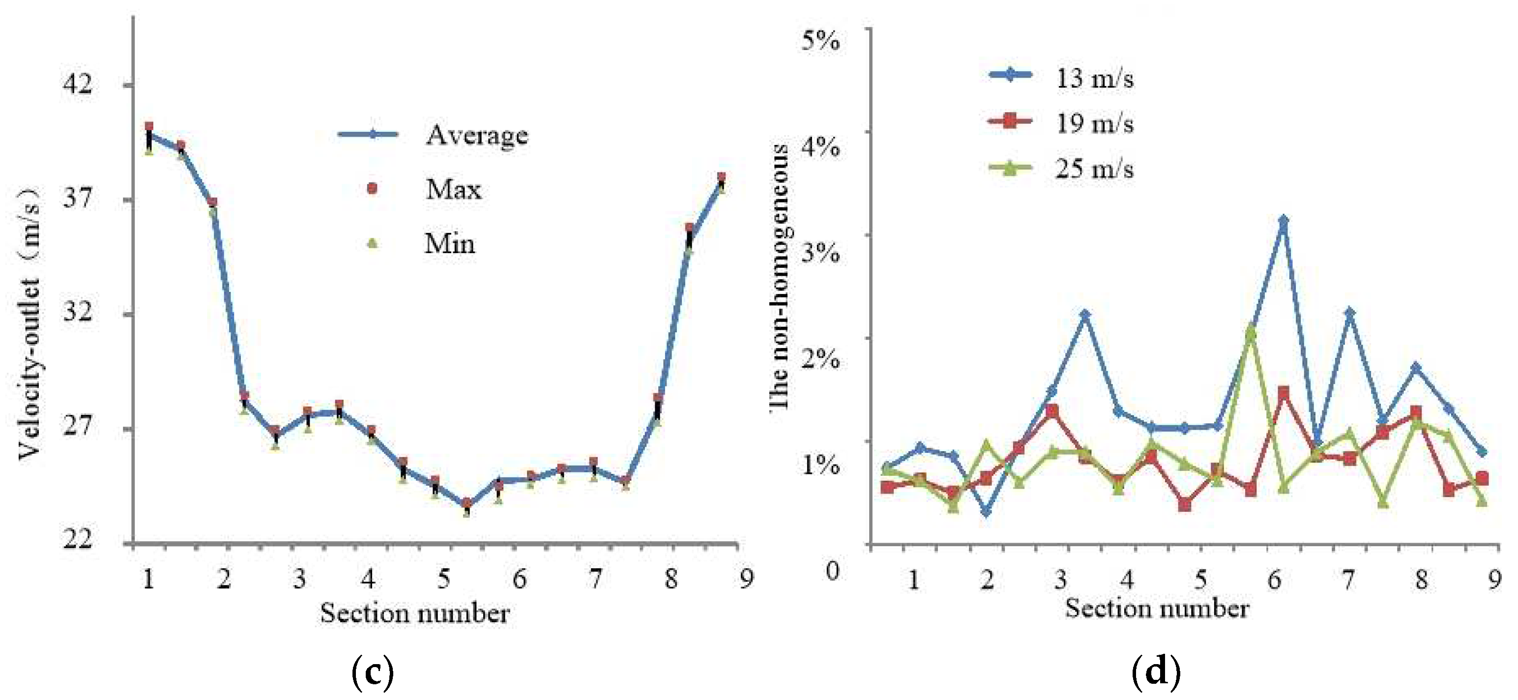
Through multiple groups of data, the mean square error M was used to analyze the uniformity of air velocity:
M = 1 N i = 1 n ( | V i V a | V a )
where Vi (m/s) is the air velocity outlet of each outlet area; Va (m/s) is the average velocity of each air outlet area; and n is the number of air outlet areas.
The value of M indicates the uniformity of air velocity in each outlet area. The smaller the value of M, the more stable the velocity in each area is and the more uniform the distribution of air velocity is, indicating that the consistency of air velocity in each area of the air outlet plate is better.
As shown in Figure 9a, with the increase in the number of plates added, the value of non-uniformity gradually decreased. When adding a partition, the value of M decreases greatly; when the number of plates increased from 1 to 2, it decreased by 13.4%; when it increased from 2 to 3 and from 3 to 4, it decreased by 10.7%. Add more than 4 pieces reduced by less than 10%, there is little change. It can be seen from Figure 9b that, on the whole, the average velocity decreases with the increase in the number of partitions. Therefore, the appropriate number of partitions can not only meet the requirements of the maximum air velocity outlet but also meet the requirements of the uniformity of the velocity distribution. After comprehensive consideration, it is recommended to install four partitions for the model studied in this paper.
In the process of tea plucking, the air outlet area is used for air supply, and the bud leaves sent by the leaf sweeping mechanism are blown into the collecting device. If the velocity in the air outlet area is too small, the tea cannot be blown into the leaf collecting box (bag). The velocity must be increased to meet the requirements for leaf collection. However, with the increase in velocity, the Reynolds number also increases. In the turbulent state, the air particles move disorderedly, and besides the motion parallel to the baffle axis, there is also a violent transverse motion. Therefore, whether it is the unstable flow field caused by the narrow flow field at the outlet or the turbulent flow field caused by the increase in velocity, it is necessary to reduce the friction and swing of the tea bud under the joint operation of the leaf collecting structure and the air outlet area to avoid a serious decline in tea quality. Through the regional division of the air outlet mechanism (symmetrical on both sides, with four air baffle plates on each side), the air outlet velocity and air direction are controlled to ensure the quality of tea.

3.3. Testing

The object of the tea plucking experiment is the fresh leaves collected by machine. The parameters of test measuring instruments are shown in Table 6. Through the fluid analysis of the front structure, several combinations with relatively high target values are obtained for experimental verification. The export of high speed combinations of (1, 1, 0, 1, 1), (1, 0, 1, 1, −1), (1, 0, 0, 1, 1), (0, 1, 1, 1, −1), (1, 0, 1, 1, 1), (1, 1, 1, 1, 1), (1, 0, 1, 1, −1), and (1, 1, 1, 1, 1), The test results were 51.31 m/s, 51.53 m/s, 50.48 m/s, 50.29 m/s, and 52.20 m/s, and 50.68 m/s, 51.30 m/s, and 50.90 m/s, respectively. The result is similar to the simulation result, X2 and X3 are insignificant terms. The tea trees are cut by the round-trip blade of the riding-type tea plucking machine and piled on the cutter head. Fresh leaves are subjected to the action of leaf-collecting wind and reach the leaf-collecting mechanism through the designed air outlet plate. (see Figure 10). In order to improve the collection efficiency of riding-type tea plucking machines, the air outlet part is key. In this paper, the optimized air outlet plate is set with four allegros symmetrical on the left and right sides to form nine air outlet areas. After the fan works smoothly in the idling state, the velocity at the air outlet of the fan and the velocity in the air outlet area are measured by the anemometer. Each area was measured three times. By comparing Figure 7 and Figure 11, it can be seen that the variation rule of air velocity outlet in each area is consistent with the previous simulation results. The velocity on the most two sides is the largest, and there is little difference in the intermediate velocity, indicating the feasibility of using the three-dimensional numerical simulation method to simulate the flow field of air outlet components. When the engine speed of the whole machine is increased, the velocity inlet increases accordingly. As shown in Table 7, the velocity outlet of each area also increases accordingly. In actual production, the engine speed can be adjusted according to the growth of tea trees to control the effect of leaf collection.
Through multiple groups of data measurements, the mean square error (M) in Table 8 is used to analyze the uniformity of each velocity outlet. According to the air velocity test data, draw the velocity relation diagram of each area as shown in Figure 11.
According to the calculation, the non-homogeneity of the air outlet area is shown in Figure 11d. Under different velocity inlets, the non-homogeneous is below 6%, indicating that the air velocity in each area of the air outlet mechanism has little difference. The results are similar to the simulation results. Under a certain velocity, the uniformity of each air outlet area is basically the same, and the quality of tea can be guaranteed.

4. Conclusions

In this paper, the riding-type tea plucking machine is taken as the research object, and the SOLIDWORKS software is used to conduct three-dimensional modeling of the plucking mechanism, leaf collecting mechanism, regulating mechanism, and walking mechanism. This riding-type tea plucking machine, through hydraulic control, can adjust the width and height according to the actual tea garden, tea shed, and tea tree growth. It has good adaptability, reduces labor intensity, and improves the efficiency of tea plucking.
An important index to measure the functional characteristics of a tea plucking machine is the quality of fresh tea leaves after plucking. One of the means to maintain the high quality of tea leaves is the design of leaf collecting mechanisms. The air outlet part of the leaf collecting mechanism of the riding-type tea plucking machine is selected as the research object. With the help of the numerical fluid simulation analysis software platform, the internal flow field of the air outlet part is simulated to show the variation and distribution of its flow field characteristics. In view of the phenomenon of uneven air velocity and internal eddy current in the air outlet, the structure of the air outlet component is optimized, and the distribution of air velocity is improved by installing a separator. At the same time, the air velocity outlet measurement test is made by using the manufactured air outlet component of the tea plucking machine.
  • Due to the growth of tea in the growth process, the tea canopy is built into a certain radian. The key is how to evenly distribute the air flow from the fan to the outlet of the cutting table. The air outlet part is designed to be the same radian as the tea shed surface. Through the collision of air flow in the cavity and the design of the outlet gap, air delivery is realized. The velocity outlet is greater than the velocity inlet, which can meet the requirements of leaf collection;
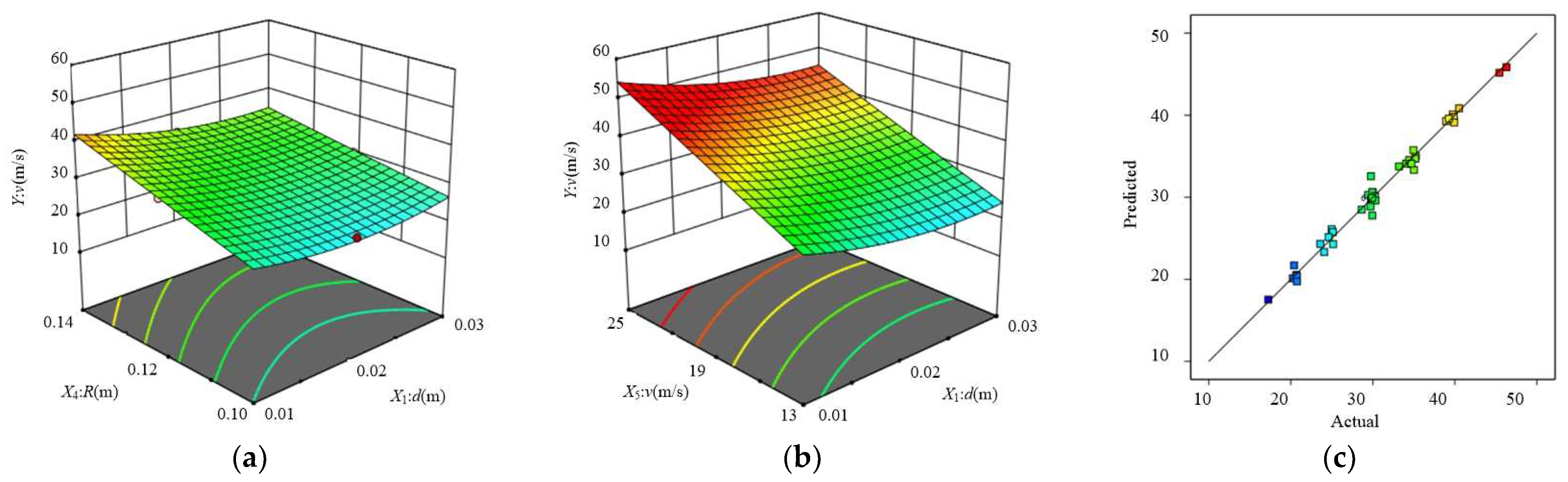
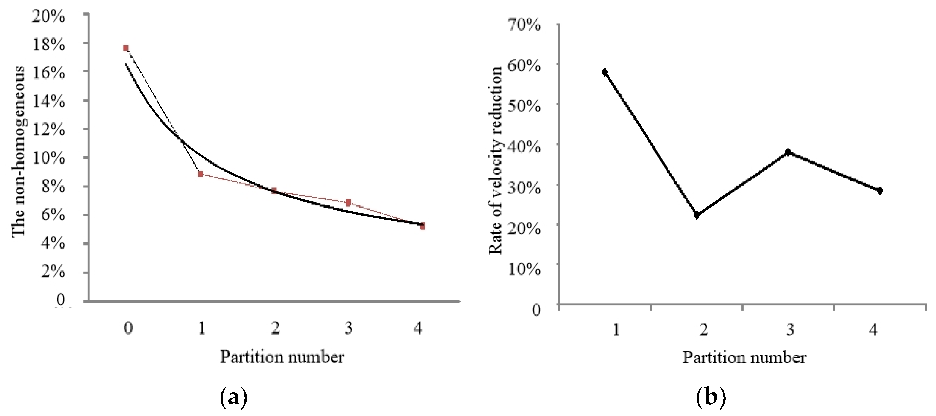
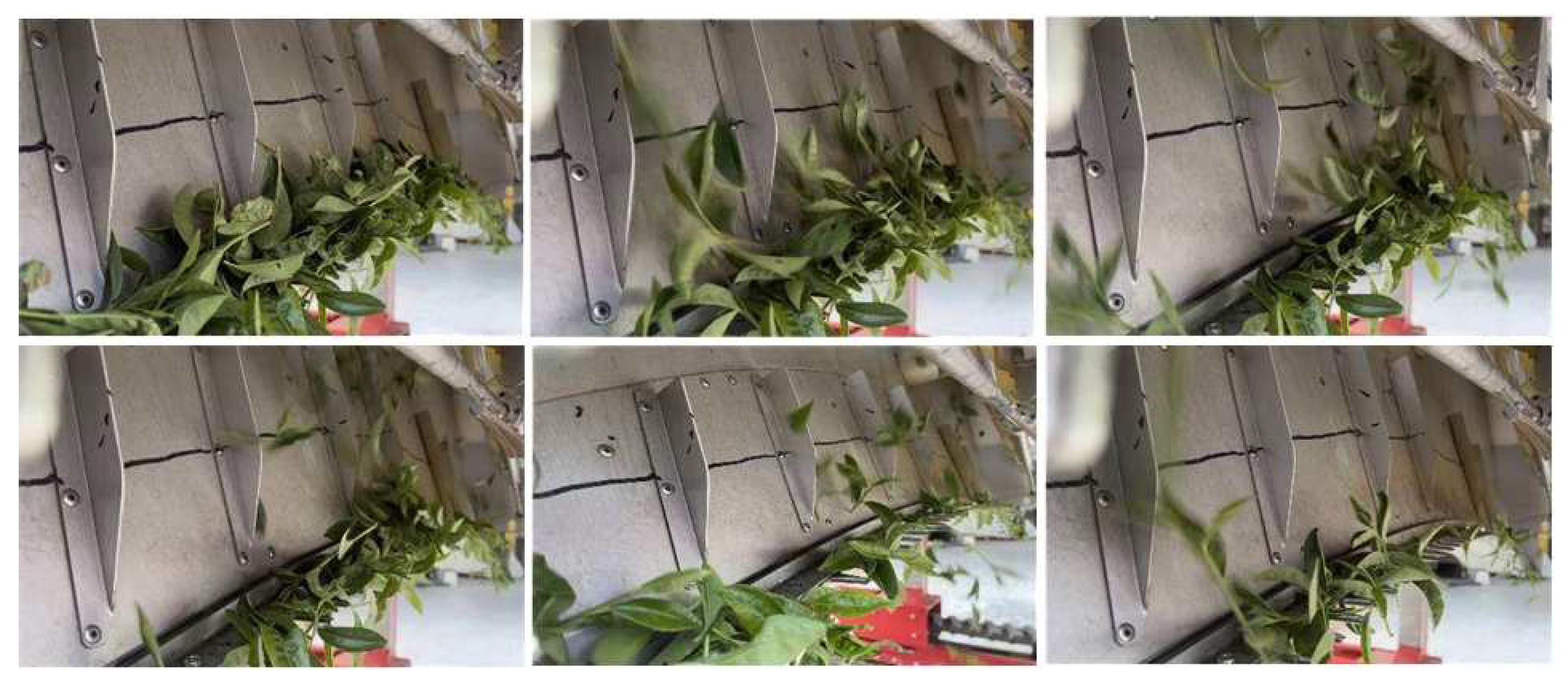
  • Through the structural design of installing a baffle on the air outlet plate, the free air flow is collected and moves upward along the baffle, so that the tea buds are blown into the collecting mechanism along the trend, realizing the diversion function and reducing the collision times between tea buds. Based on Box–Behnken’s central combination design theory, the working parameters of the air outlet system are optimized. The test results show that the main order of influence of the velocity outlet is the velocity inlet, the height of the outlet end, and the length of the inlet end. The optimal parameter combination is as follows: height of the outlet end X1, length of the inlet end X2, and velocity inlet are 0.01 m, 0.03 m, and 25 m/s, respectively. The corresponding velocity outlet is 53.35 m/s. Through fluid simulation, the distribution of the velocity flow field under different numbers of partitions is analyzed. When the number increases, the non-homogeneity can be significantly reduced. When the number exceeds four, the increase in the number does not significantly improve the uniformity of distribution. At the same time, considering that the air velocity outlet should not be too small, the structure of the air outlet parts is optimized, and 4 partitions are installed on the left and right sides to improve the internal flow field and improve the quality of tea buds;
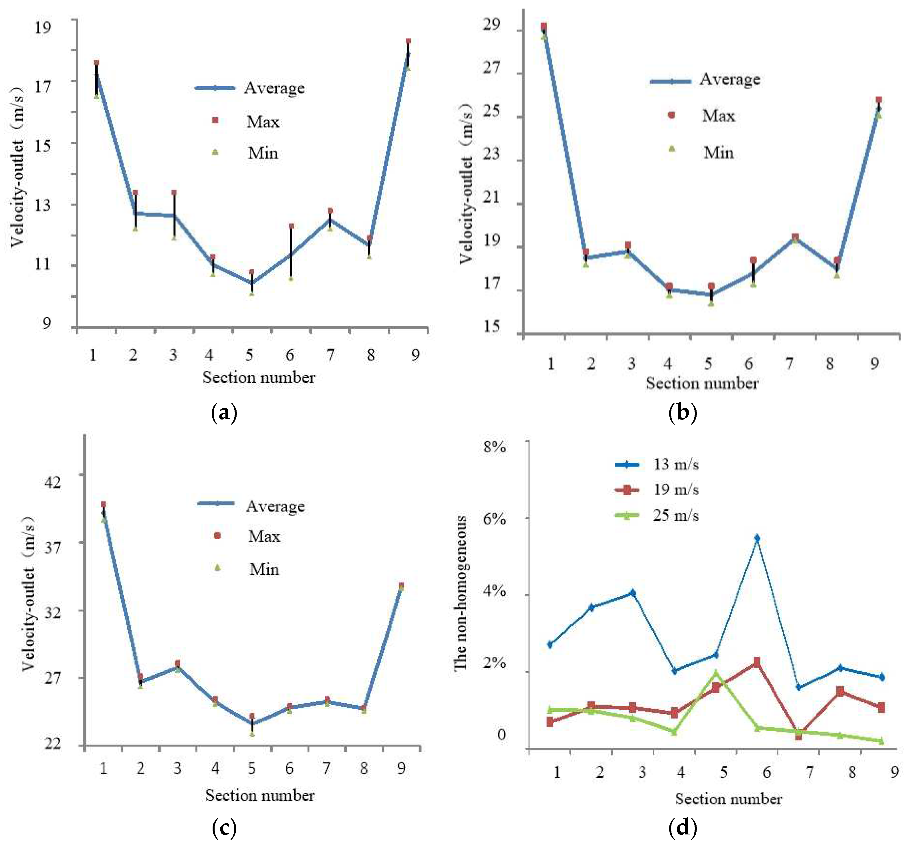
  • In order to achieve the minimum non-homogeneity of the air velocity outlet in each outlet area, the structure of the outlet air part of the tea plucking machine is optimized. The optimized mechanism simulated the velocity flow field, and compared with the test results, the velocity inlet accelerated from 13 m/s to 25 m/s, and the distribution law of velocity change in each region is consistent. The velocity inlet increased, and the velocity outlet also increased. That is, there is a certain positive relationship between the engine speed, fan speed, the velocity inlet of the air outlet mechanism, and the velocity outlet, so the effect of blade collection can be controlled by adjusting the engine speed (the faster the engine speed, the faster the fan speed). The increase of fan speed leads to an increase in the velocity inlet and velocity outlet of the collecting mechanism. The simulation and experimental results show that the mathematical model is relatively accurate, which provides a reliable theoretical basis for the optimal design of the tea plucking machine structure.
Although the mathematical description of the simulation algorithm and the actual working condition of the gap, as well as the simulation calculation of multiple iteration operations, generated rounding errors. The research process is based on an orifice-plate throttling pipeline; it is representative. The ideas and methods can be used in two-phase flow conditions similar to throttling characteristics and complex flow fields, and they are practical in engineering.

Author Contributions

Conceptualization, X.W.; methodology, D.T.; software, X.W.; validation, D.T. and C.C.; formal analysis, G.W. and B.C.; investigation, G.W., L.Z., M.Y. and X.H.; data curation, D.L. and L.J.; writing—original draft preparation, X.W.; writing—review and editing, D.T.; project administration, C.C. All authors have read and agreed to the published version of the manuscript.

Funding

This research was funded by the Key Research and Development Program of Zhejiang Province, China, grant number 2021C02028.

Institutional Review Board Statement

Not applicable.

Data Availability Statement

Data available on request due to privacy.

Conflicts of Interest

The authors declare no conflict of interest.

References

  1. Cabrera, C.; Artacho, R.; Ginmenez, R. Beneficial effects of green tea-a review. J. Am. Coll. Nutr. 2006, 25, 79–99. [Google Scholar] [CrossRef] [PubMed]
  2. Liang, G.Z.; Dong, C.W.; Hu, B.; Zhu, H.K.; Yuan, H.B.; Jiang, Y.W.; Hao, G.S. Prediction of moisture content for congou black tea withering leaves using image features and nonlinear method. Sci. Rep. 2018, 8, 7854. [Google Scholar] [CrossRef] [PubMed]
  3. Wu, C.Y.; Qian, J.; Zhang, J.Y.; Wang, J.; Li, B.; Wei, Z.B. Moisture measurement of tea leaves during withering using multifrequency microwave signals optimized by ant colony optimization. J. Food Eng. 2022, 335, 111174. [Google Scholar] [CrossRef]
  4. Chen, Y.T.; Chen, S.F. Localizing plucking points of tea leaves using deep convolutional neural networks. Comput. Electron. Agric. 2020, 171, 105298. [Google Scholar] [CrossRef]
  5. Xu, W.K.; Zhao, L.G.; Li, J.; Shang, S.Q.; Ding, X.P.; Wang, T.W. Detection and classification of tea buds based on deep learning. Comput. Electron. Agric. 2022, 192, 106547. [Google Scholar] [CrossRef]
  6. Zhang, L.; Zou, L.; Wu, C.Y.; Jia, J.M.; Chen, J.N. Method of famous tea sprout identification and segmentation based on improved watershed algorithm. Comput. Electron. Agric. 2021, 184, 106108. [Google Scholar] [CrossRef]
  7. Gan, N.; Sun, M.F.; Lu, C.Y.; Li, M.H.; Wang, Y.J.; Song, Y.; Ning, J.M.; Zhang, Z.Z. High-speed identification system for fresh tea leaves based on phenotypic characteristics utilizing an improved genetic algorithm. J. Sci. Food Agric. 2022, 102, 6858–6867. [Google Scholar] [CrossRef]
  8. Lin, Y.K.; Chen, S.F.; Kuo, Y.F.; Liu, T.L.; Lee, S.Y. Developing a guiding and growth status monitoring system for riding-type tea plucking machine using fully convolutional networks. Comput. Electron. Agric. 2021, 191, 106540. [Google Scholar] [CrossRef]
  9. Sharma, V.S. Integration of agro-techniques for higher plucker productivity and lower harvesting costs. Tea Sci. 2004, 3, 3–4. [Google Scholar]
  10. Han, Y.; Xiao, H.R.; Qin, G.M.; Song, Z.Y.; Ding, W.Q.; Mei, S. Developing Situations of Tea Plucking Machine. Engineering 2014, 6, 268–273. [Google Scholar] [CrossRef]
  11. Li, C.; Ji, S.M.; Tan, D.P. Softness abrasive flow method oriented to tiny scale mold structural surface. Int. J. Adv. Manuf. Technol. 2012, 61, 975–987. [Google Scholar] [CrossRef]
  12. Chen, J.L.; Xu, F.; Tan, D.P. A control method for agricultural greenhouse heating based on computational fluid dynamics and energy prediction model. Appl. Energy 2015, 141, 106–118. [Google Scholar] [CrossRef]
  13. Wang, T.; Li, L.; Yin, Z.C.; Xie, Z.W.; Wu, J.F.; Zhang, Y.C.; Tan, D.P. Investigation on the flow field regulation characteristics of the right-angled channel by impinging disturbance method. Proc. Inst. Mech. Eng. Part C J. Mech. Eng. Sci. 2022, 236, 11196–11210. [Google Scholar] [CrossRef]
  14. Lian, G.P.; Thiru, A.; Parry, A.; Moore, S. CFD simulation of heat transfer and polyphenol oxidation during tea fermentation. Comput. Electron. Agric. 2002, 34, 145–158. [Google Scholar] [CrossRef]
  15. Dhekne, P.P.; Patwardhan, A.W. CFD model for transient flow fields around teabag during tea infusion. Food Bioprod. Process. 2021, 130, 79–91. [Google Scholar] [CrossRef]
  16. Jaime, G.C.; José, A.G.; Christian, O.D.; Rubén, G.; Sergio, V.; Francisco, C.; Raúl, L. Numerical study of the thermolysis of catechins in green tea. J. Food Process Eng. 2019, 42, e13152. [Google Scholar]
  17. Weng, X.X.; Chen, C.Q.; Wang, G.; Wei, Z.B.; Jiang, L.; Hu, X.R. Numerical Simulation of Leaf Gathering Process of Fresh Leaf Collecting Pipeline Based on CFD–DEM. Trans. Chin. Soc. Agric. Mach. 2022, 53, 424–432. [Google Scholar]
  18. Vijayan, V.; Vivekanandan, M.; Venkatesh, R.; Rajaguru, K.; Antony, A.G. CFD modeling and analysis of a two-phase vapor separator. J. Anal. Calorim. 2021, 145, 2719–2726. [Google Scholar] [CrossRef]
  19. Daza-Gómez, M.A.M.; Pereyra, E.; Ratkovich, N. CFD simulation of two-phase gas/non-Newtonian shear-thinning fluid flow in pipes. J Braz. Soc. Mech. Sci. Eng. 2019, 41, 506. [Google Scholar]
  20. Ji, S.M.; Weng, X.X.; Tan, D.P. Research on the precision processing method for softness abrasive two-phase flow based on LSM. In Proceedings of the 2010 International Conference on Networking, Sensing and Control (ICNSC), Chicago, IL, USA, 10–12 April 2010; pp. 53–57. [Google Scholar]
  21. Jones, W.P.; Launder, B.E. The prediction of laminarization with a two-equation model of turbulence. Int. J. Heat Mass Transf. 1972, 15, 301–314. [Google Scholar] [CrossRef]
  22. Mullya, S.; Karthikeyan, G.; Ganachari, V. Simulation of flow-field and debris temperature analysis in micro-electrical discharge milling using slotted tools. Proc. Inst. Mech. Eng. Part B J. Eng. Manuf. 2022, 236, 1169–1180. [Google Scholar] [CrossRef]
  23. Ermakova, E.; Elberdov, T.; Rynkovskaya, M. Shape Optimization of a Shell in Comsol Multiphysics. Computation 2022, 10, 54. [Google Scholar] [CrossRef]
  24. Yang, X.; Ma, J.; Li, Y.; Sun, X.; Jia, X.; Li, Y. Wall Stresses in Cylinder of Stationary Piped Carriage Using COMSOL Multiphysics. Water 2019, 11, 1910. [Google Scholar] [CrossRef]
  25. Li, J.Y.; Su, N.N.; Wei, L.L.; Zhang, X.M.; Yin, Y.L.; Zhao, W.H. Study on the surface forming mechanism of the solid–liquid two-phase grinding fluid polishing pipe based on large eddy simulation. Proc. Inst. Mech. Eng. Part B J. Eng. Manuf. 2019, 233, 2505–2514. [Google Scholar] [CrossRef]
  26. Fu, J.L.; Zhang, J.; Ding, G.F.; Qin, S.F.; Jiang, H.F. Determination of vehicle requirements of AGV system based on discrete event simulation and response surface methodology. Proc. Inst. Mech. Eng. Part B J. Eng. Manuf. 2021, 235, 1425–1436. [Google Scholar] [CrossRef]
  27. Lan, Z.; Gong, B. Uncertainty analysis of key factors affecting fracture height based on box-behnken method. Eng. Fract. Mech. 2020, 228, 106902. [Google Scholar] [CrossRef]
Figure 1. Configuration of (a) a side view of the riding-type tea plucking machine, (b) the leaf collecting mechanism, and (c) the picking mechanism.
Agriculture 13 00946 g001
Figure 2. Three-dimensional drawing. (a) Cutting table of the tea machine (front). (b) Cutting table of the tea machine (rear). (c) Key components of tea plucking (front). (d) Key components of tea plucking (rear).
Agriculture 13 00946 g002
Figure 3. The physical model of the air component. (a) Air outlet structure drawing and grid model. (b) Schematic diagram of the cutter outlet mechanism. (c) Profile dimension parameter of the cutting outlet mechanism.
Agriculture 13 00946 g003
Figure 4. Flow field characteristics of the outlet structure. (a) Meshing. (b) Cell mass histogram. (c) External flow field. (d) Internal flow field.
Agriculture 13 00946 g004
Figure 5. Flow field distribution and velocity outlet trend diagram (velocity inlet = 25 m/s). (a) Flow field at d = 0.01 m. (b) At different d values. (c) Flow field at l1 = 0.05 m. (d) At different l1 values. (e) Flow field at l2 = 0.02 m. (f) At different l2 values. (g) Flow field at R = 0.1 m. (h) At different R values.
Agriculture 13 00946 g005
Figure 6. Diagram of the air outlet plate. (a) Air outlet area division. (b) Diagram of the measuring points.
Agriculture 13 00946 g006
Figure 7. Under different initial velocity inlets, the velocity distribution and the non-homogeneity of each region of the blade collector plate. (a) Velocity inlet = 13 m/s. (b) Velocity inlet = 19 m/s. (c) Velocity inlet = 25 m/s. (d) The non-homogeneous.
Agriculture 13 00946 g007aAgriculture 13 00946 g007b
Figure 8. Effect of all factors on velocity inlet. (a) l1 = 0.05 m, l2 = 0.01 m, v = 19 m/s. (b) l1 = 0.05 m, l2 = 0.01 m, and R = 0.14 m. (c) Predicted vs. actual.
Agriculture 13 00946 g008
Figure 9. Flow velocity variation of outlet structure. (a) The non-homogeneous. (b) Rate of velocity reduction.
Agriculture 13 00946 g009
Figure 10. The process of fresh leaf harvesting by machine.
Agriculture 13 00946 g010
Figure 11. Under different initial velocity inlets, the velocity distribution (measured) and the non-homogeneity of each region of the blade collector plate. (a) Velocity inlet = 13 m/s. (b) Velocity inlet = 19 m/s. (c) Velocity inlet = 25 m/s. (d) The non-homogeneous.
Agriculture 13 00946 g011
Table 1. The main composition of the tea plucking machine.
MechanismIntroduction
Plucking mechanismCutter motion and leaf sweep components
Leaf collecting mechanismBlower and outlet components
Regulating mechanismAdjust with the height of the tea canopy
Walking mechanismWalking through the crawler site
Table 2. Parameters and boundary conditions of the simulated test fluid.
TypeItemMethod or Value
Simulation parametersGeometric space3D
Number of grids599,122
Turbulence modelStandard k-ε
Discretization methodSecond order upwind
Wall modelNo slip
SolverPressure and implicit solver
Temperature293 K
Density (solid-fresh leaf)532 kg/m3
Poisson’s ratio (solid-fresh leaf)0.4
Density (gas-air)1.22 kg/m3
Viscosity (gas-air)1.225 × 10⁻⁵ Pa∙s
Boundary conditionInlet boundaryVelocity inlet
Velocity inlet(13~25) m/s
Outlet boundaryPressure-outlet
Pressure value102,325 Pa
Acceleration of gravity9.8 m/s2
Table 3. Codes of testing factors.
CodesTesting Factors
d/(m)ll/(m)l2/(m)R/(m)Velocity Inlet/(m∙s−1)
−10.010.0100.1013.00
00.020.030.010.1219.00
10.030.050.020.1425.00
Table 4. Experimental design scheme and response values.
No.Testing FactorsY/(m∙s−1)
X1X2X3X4X5
1001−1024.98
200−1−1025.16
310−10029.94
40000029.92
501−10029.89
60−110030.32
71000−120.40
80011029.77
9100−1029.94
100000029.92
111001035.01
1200−10−120.73
131010029.77
140−10−1025.12
15000−1133.19
160001146.29
171−100029.98
180000029.92
190000029.92
20−100−1028.64
21−1001040.52
221000139.26
23000−1−117.25
2400−11034.95
250010139.91
260−100−120.66
270110029.71
28−10−10034.43
29−1010034.66
3000−10139.88
311100029.43
320001−124.07
330101034.70
340010−120.75
350−100139.74
36−1000145.43
370−101035.17
38−1000−123.60
390−1−10030.27
40−1−100035.24
410000029.92
420100−120.24
430100138.93
44010−1024.61
450000029.92
46−1100034.08
Table 5. Variance analysis of regression equation.
SourceVelocity Outlet
Sum of SquaresdfMean SquareF-Valuep-Value
Model1996.672099.8388.26<0.0001
X1-d67.52167.5259.69<0.0001
X2-l11.5111.511.330.2592
X3-l21.8111.811.600.2176
X4-R320.451320.45283.28<0.0001
X5-v1500.2511500.251326.27<0.0001
X1X20.092110.09210.08140.7777
X1X30.039010.03900.03450.8542
X1X411.57111.5710.230.0037
X1X52.2112.211.950.1748
X2X30.013210.01320.01170.9148
X2X40.000410.00040.00030.9855
X2X50.038410.03840.03400.8553
X3X46.27016.275.540.0267
X3X50.000110.00010.00010.9929
X4X59.88019.888.730.0067
X1260.630160.6353.60<0.0001
X220.020210.02020.01790.8946
X320.767710.76770.67860.4178
X420.028910.02890.02550.8744
X520.167410.16740.14800.7037
Residual28.28251.13
Lack of fit28.28201.41
Pure error050
Cor total2024.9545
Table 6. Description of the measuring instrument.
ModelKestrel 2500
Wind velocity 0.4~60 m/s
Resolution ratio0.01 m/s
Response time ≤3 s
Detection precision±3%
Table 7. Velocity outlet measurement statistics.
AreaSpeed of engine/(r∙min−1)
100015002000
Velocity inlet/(m∙s−1)
131925
Velocity outlet/(m∙s−1)
116.5017.4817.6128.7229.1029.2139.1039.8238.70
213.4112.2012.5218.2018.7818.4926.6127.1026.38
311.9012.5813.3718.7019.1118.6227.6128.1027.59
411.1210.6911.3016.7817.1117.2125.4025.2025.11
510.8210.1110.4117.2016.3816.8123.7224.2122.90
611.2012.3210.6117.6917.3018.4124.6224.8824.90
712.2112.8212.5019.5119.4219.3025.4125.2025.11
811.2811.8011.9117.8818.3917.7024.6124.8124.79
918.3218.0117.3625.1025.2825.8133.7033.8033.59
Table 8. M at different velocity inlets.
Velocity13 m/s19 m/s25 m/s
M
Area
12.71%0.69%1.02%
23.67%1.08%1.00%
34.05%1.06%0.80%
42.01%0.91%0.44%
52.45%1.59%1.98%
65.47%2.25%0.54%
71.60%0.34%0.44%
82.10%1.48%0.36%
91.86%1.05%0.20%
Disclaimer/Publisher’s Note: The statements, opinions and data contained in all publications are solely those of the individual author(s) and contributor(s) and not of MDPI and/or the editor(s). MDPI and/or the editor(s) disclaim responsibility for any injury to people or property resulting from any ideas, methods, instructions or products referred to in the content.

