Article

System Design, Analysis, and Control of an Intelligent Vehicle for Transportation in Greenhouse

Logistics Engineering College, Shanghai Maritime University, Shanghai 201306, China
*
Author to whom correspondence should be addressed.
Agriculture 2023, 13(5), 1020; https://doi.org/10.3390/agriculture13051020
Submission received: 25 April 2023 / Revised: 3 May 2023 / Accepted: 5 May 2023 / Published: 7 May 2023

Abstract

:
Smart agriculture represents a significant trend in agricultural development, given its potential to enhance operational efficiency and reduce labor intensity. Despite the adoption of modern greenhouse technologies, such as sensors and automation systems, crop transportation is still largely achieved through manual labor, largely due to the complex environment and narrow terrain of greenhouses. To address this challenge, this work proposes the design of an intelligent vehicle that is capable of transporting crops in a commercial greenhouse, with the aim of improving operational efficiency and reducing labor intensity. To enable the vehicle to navigate the horizontal and rail surfaces within the greenhouse, a novel chassis structure is designed that is capable of simultaneous driving on both ground and rail surfaces. Additionally, the two-dimensional codes is adopted for positioning and navigation, thereby avoiding the need to modify existing greenhouse road surfaces. Through the implementation of a comprehensive system-control strategy, the intelligent vehicle realized various functions, including ground driving, rail driving, moving up and down the rail, and automatic rail changing. Experimental results demonstrate that the designed intelligent vehicle successfully meets the basic requirements for crop transportation in a greenhouse, providing a solid foundation for future unmanned operations.

1. Introduction

Thanks to improvements in agricultural information and intelligence, the adoption of smart agricultural systems is rapidly increasing. The combination of computer networks, the Internet of Things (IoT), audio and video, wireless communication, expert systems, and other associated technologies [1] in smart agriculture enable real-time remote monitoring [2], environmental control [3], harvesting [4], disease warning [5,6], and identification [7,8]. The future of agricultural development will continue to embrace the trend of smart agriculture. This approach has the potential to enhance agricultural management and production models; minimize the consumption of unnecessary resources such as labor, materials, and finances; and boost the efficiency of agricultural production. The integration of intelligent vehicles into smart agriculture is progressively enabling agronomic automation [9,10]. Intelligent vehicles possess a free movement mode, allowing them to autonomously travel from the farm to a predetermined location. These vehicles exhibit various features, such as automatic barriers, the real-time transmission of on-site images and sensor-collected environmental data, and automatic homing [11,12]. Agricultural robots designed for greenhouses differ from those intended for outdoor farms in terms of their design and control features as greenhouses are closed environments, unlike open agricultural spaces. The mobility and trafficability of smart cars for greenhouses pose the greatest challenges [13,14]. Key technologies include independent navigation, obstacle avoidance, real-time precise positioning, chassis design, drive control, map exploration and creation, path planning, and rail railing control.
The advancement of artificial intelligence and improvements in computer hardware performance have facilitated the development of intelligent mobile platforms for agriculture. Various types of vehicles are employed in greenhouses, as outlined in a comprehensive review by Aslan et al. [15]. Greenhouse intelligent vehicles can be classified into crawler, wheel, and rail types, based on their propulsion systems. The advancement of artificial intelligence and improvements in computer hardware performance have facilitated the development of intelligent mobile platforms for greenhouses. Grimstad et al. [16] developed a low-cost, lightweight, and practical multifunctional agricultural robot mobile platform that can effectively operate in diverse planting environments. A control drive system and multi-sensor fusion are utilized for fruit and vegetable transportation systems. Ye et al. [17] designed a planting plant capable of operating between fruit tree ridges and on relatively flat ground, featuring an autonomous robotic platform for orchard management that can turn and walk independently. Li et al. [18] designed a flexible chassis test prototype based on the principle of four-wheel independent drive and four-wheel independent steering, in accordance with the actual operational requirements of facility agriculture. Zhao et al. [19] designed and tested a dual-arm robot for tomato harvesting in greenhouses, which moves along a rail. Roldan et al. [20], a heterogeneous robot team, consisting of both ground and aerial vehicles, explored the monitoring of environmental variables in greenhouses. A greenhouse with a corridor and heating pipes is a type of enclosed structure that is designed to create an ideal environment for growing plants. Meng et al. [21] developed a multifunctional intelligent vehicle that can move on both surfaces. In the Netherlands, a picking robot named "SWEEPER" was designed to leverage the characteristics of multi-span greenhouse planting conditions, utilizing the heating pipes present in greenhouses [22].
In addition to the various mechanical types of intelligent vehicles, system navigation, positioning, and control are crucial for greenhouse vehicles. In terms of navigation, ground orbital systems can facilitate vehicle movement by installing a steering rail on the greenhouse floor, thanks to their simple structure, easy installation, and handling. Typically, orbital navigation comprises two types: ground and hanging. By placing the vehicle’s guidance route on the rail, the navigation difficulty is reduced. However, this equipment is subject to strict range limitations, and once the rail is installed, it is challenging to modify the existing rail path. Railing navigation technology can be applied more broadly. Other navigation methods include electromagnetic navigation [23], visual navigation [10], and LiDAR [24,25]. Greenhouse mobile platforms can also employ wheel information for navigation purposes [26]. In recent years, wireless railing navigation technology has been utilized in the field of facility agriculture. Positioning and navigation methods based on wireless technology include sonic positioning and navigation [27,28], wireless local area networks [29], radio frequency identification [30], and ultra-wideband [31,32]. Railing navigation is the most widely used navigation method for greenhouse intelligent robots. Navigation accuracy is influenced not only by sensor precision but also by image and data processing algorithms. Accurate trajectory railing is a crucial prerequisite for greenhouse mobile platforms. However, due to errors and disturbances, achieving optimal speed railing in real applications is challenging [33]. To estimate disturbances and correct modeling errors, a nonlinear disturbance observer technique was presented in the literature [34]. A sliding mode control strategy based on an extended state observer was proposed to follow the trajectory of mobile robots while accounting for unknown disturbances and uncertainties [35,36]. A fuzzy-model-based control framework has also been employed to address highly uncertain behavior and vehicle dynamics [37].
In recent years, significant advancements have been made in greenhouse intelligent mobile platforms. Table 1 highlights the various types of intelligent vehicles designed for use in greenhouses, showcasing a diverse range of driving road conditions. To accommodate these differing conditions, intelligent vehicle designs are categorized according to their respective driving mechanisms, including single-wheel drive (1WD), two-wheel drive (2WD), four-wheel drive (4WD), and four-wheel drive with independent steering (4WD4S). To switch between different rows, manual and automatic methods are employed. Of the various automatic row-switching methods, only a few include the capability to switch seamlessly between rail and flat roads. To solve this problem, this work designs an intelligent mobility platform for various driving surfaces in greenhouses. The contributions of this work are as follows:
  • The design of an intelligent vehicle for greenhouses, which can automatically switch between rail and flat ground;
  • The adoption of a low-cost, reliable method for vehicle positioning and navigation without changing the existing environment;
  • The verification of the effectiveness of a designed vehicle on road surfaces, and track driving and rail switching via a greenhouse test.

2. System Requirement and Design

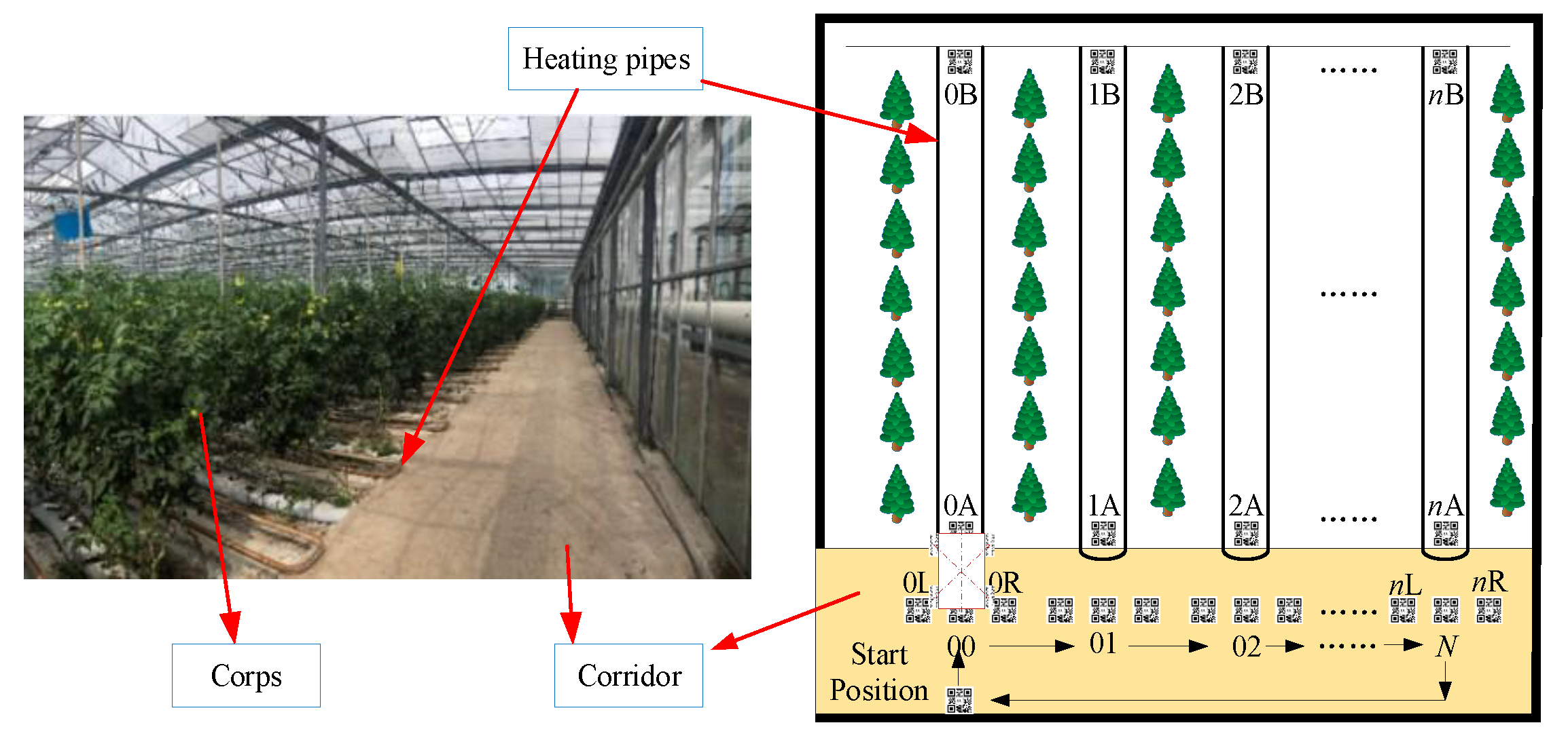
2.1. Environment of Greenhouse

This work was carried out in a commercial greenhouse in accordance with the standard NEN-EN 13031-1:2019/AC:2022. This standard outlines the essential design and construction guidelines for commercial greenhouses, such as the heating system. The heating pipes are strategically placed throughout the greenhouse to ensure even heat distribution. Usually, these pipelines can also carry vehicles, which is convenient for workers to carry out similar picking and spraying operations. In the existing operation process, the work vehicle is manually operated. After working in one row, it is then manually changed to another row, and the operation is repeated until the finish the last row. In this work, the greenhouse measures 150 m in length and 200 m in width, featuring a transparent glass roof and a light control system to regulate lighting duration. There are two types of internal road surfaces: a flat concrete road and a tube rail, which serves as the heating pipe. The rail is situated on one side of the flat concrete surface, with an internal support mechanism ensuring that the rail remains level. The current operating method is manual, requiring effort to transition the vehicle between the flat concrete road and the rail, which can be particularly labor-intensive during harvest and planting seasons. The rail length is 150 m, the rail width is 0.48 m, the rail diameter is 0.05 m, the distance between two adjacent rails is 1.6 ± 0.1 m, and the width of the flat concrete road surface is 2.5 m.
The intelligent vehicle serves as the fundamental platform for transportation, and it must possess specific load capacities. The unloaded mass of the vehicle should be less than or equal to 50 kg, and the rated load should be greater than or equal to 100 kg. The vehicle must maintain stability when operating on both the rail and ground. Dual-mode functionality with automatic transitioning is necessary to fulfill the requirements for movement on rails and ground surfaces. Table 2 shows the design requirements of intelligent vehicle for greenhouses. Additionally, the vehicle must exhibit adequate speed and acceleration in both ground and rail modes. The positioning and navigation system of the vehicle should enable it to operate in greenhouses according to predetermined routes and autonomously travel to accurately reach target points. Consequently, the design requirements for the plant-protection vehicle include:
  • The intelligent vehicle must autonomously switch between flat ground and rail without altering the existing internal environment of the greenhouse.
  • The positioning and navigation system should be as simple and feasible as possible, enabling unattended or remote control functionality within the closed environment of the greenhouse.
  • The designed plant-protection vehicle must have a sufficient carrying capacity to perform tasks such as transportation or spraying.

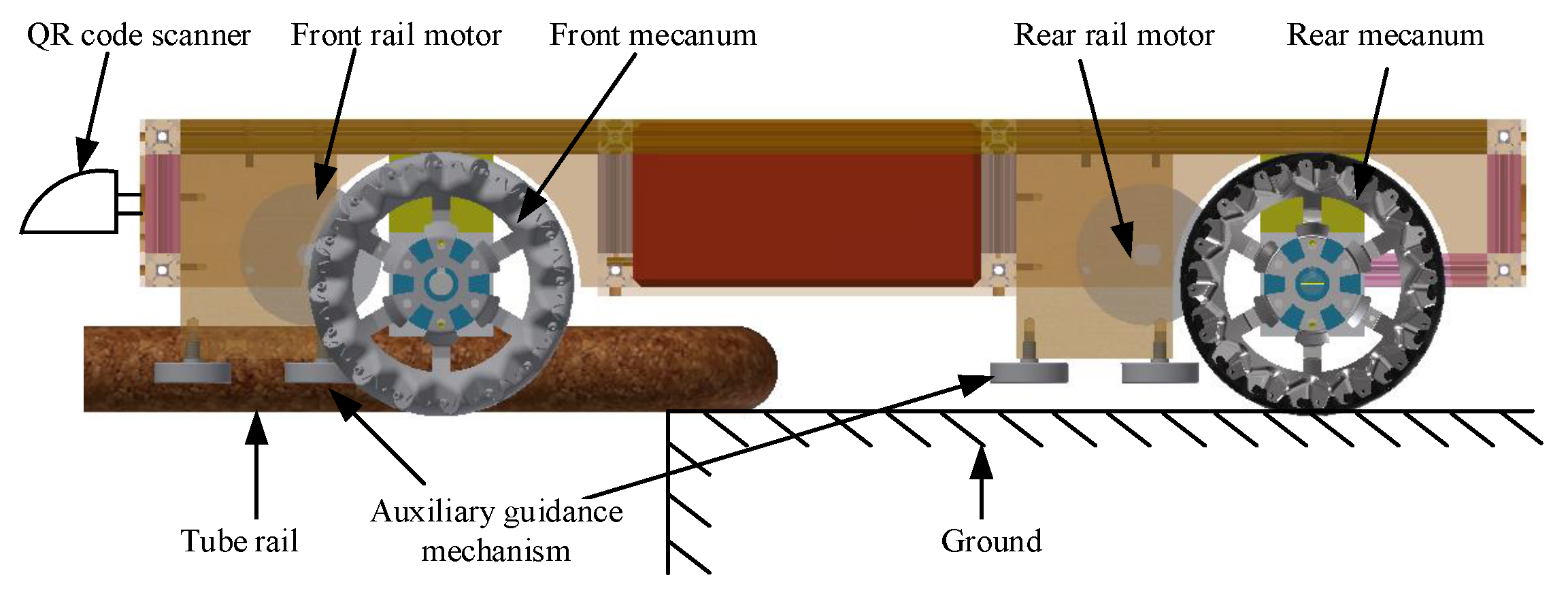
2.2. Vehicle Chassis Design

The vehicle chassis primarily comprises two components: the driving mechanism for flat ground and the tube rail. The driving mechanism of a intelligent vehicle typically involves two aspects: wheel-driven and roller-driven. The wheel-driven mechanism is primarily used for operation on horizontal ground and is achieved by installing four mecanum wheels on the chassis. Conversely, the roller-driven mechanism is primarily used for operation on rails and is achieved by installing two rollers on the chassis. The system structure of the driving mechanism is depicted in Figure 1.
The intelligent vehicle primarily consists of a mecanum wheel-drive mechanism, a roller drive mechanism, a control module, a positioning navigation module, and other components. The main materials used for the vehicle are aluminum and acrylic plastic. The mecanum wheel drive and roller drive mechanism are mounted on the bottom of the vehicle, including the mecanum wheel, motor, rubber-coated roller, guide wheel, and other auxiliary modules. The control module and power supply for the vehicle are installed in the middle of the vehicle, while the positioning navigation module, which mainly consists of a two-dimensional code scanner, is mounted at the front of the vehicle. The vehicle is 0.96 m in length, 0.66 m in width, and 0.28 m in height. The center distance between the front and rear mecanum wheels is 0.62 m, the center distance between the left and right mecanum wheels is 0.50 m, and the center distance between the two rollers is 0.48 m. The mecanum wheel has a diameter of 0.152 m, and the roller has a diameter of 0.082 m.

2.2.1. Ground-Driven Mechanism

The four mecanum wheel drive mechanism is located at the bottom of the vehicle. Each mecanum wheel is independently driven by a brushless DC motor. The mecanum wheel consists of rims and rollers. The rollers have two rotational directions, as illustrated in Figure 2. Mecanum wheels cannot be used individually; they are typically used in pairs, with two left-handed and two right-handed wheels, to achieve arbitrary movement on the horizontal plane.
There are several ways to install the mecanum wheels, primarily categorized into X-square, X-rectangle, O-square, and O-rectangle configurations. Here, X and O represent the shapes of rollers on the four mecanum wheels in contact with the ground, respectively [50]. The wheel drive mechanism designed in this work uses two left-handed and two right-handed wheels, symmetrically installed in an O-shaped rectangle. The shape of rollers on the four wheels in contact with the ground is O-shaped, while the center-line of four wheels is rectangular (as shown in Figure 1). This design allows the vehicle to move in all directions on the horizontal plane. When the vehicle needs to move on ground, the wheel drive mechanism is activated. To switch rails, for example, when the operation is completed on one rail and needs to transition to another, the vehicle only needs to coordinate the four wheels on the ground surface, traversing the entire body from one rail to another without steering. The four-wheel mechanism enhances the vehicle’s mobility in the narrow spaces inside greenhouses, avoiding body posture adjustments such as turning, reducing position errors, and facilitating unmanned operations.

2.2.2. Tube-Rail-Driven Mechanism

To ensure the smooth operation of the intelligent vehicle on the rail, the roller-drive device primarily consists of two roller drive mechanisms and two pairs of guide wheels. The driving motor of the roller driving mechanism is installed inside the roller. When the vehicle operates on the road surface, the rotating roller is elevated above the ground. As the vehicle moves onto the rail, the roller is placed on the rail, as illustrated in Figure 2. A pair of guide wheels is installed at the front and rear ends of the two rollers. This installation method enables the roller drive mechanism to adjust the vehicle’s attitude before the railing, ensuring effective railing for the roller drive mechanism. As the rear roller successively contacts the rail, friction between the roller and rail contact surface ensures the intelligent vehicle runs smoothly on the rail. The two pairs of guide wheels not only help with vehicle railing but also prevent the vehicle from overturning or derailing on the rail.

3. Localization and Navigation
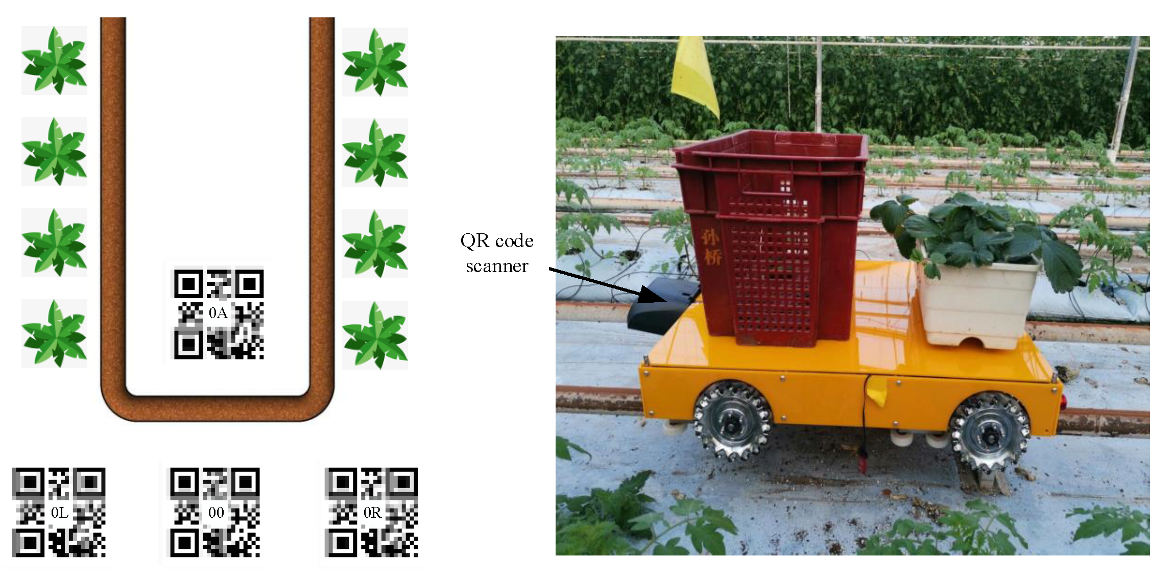
3.1. Localization

Positioning and navigation systems are crucial technologies for autonomous vehicles. As mentioned before, numerous positioning and navigation methods exist for intelligent vehicles, with most of them being suitable for open and less complex environments. For positioning and navigation technology within a greenhouse, it is essential to design a low-cost and reliable approach to ensure that intelligent vehicles achieve autonomous driving according to a predetermined route. Some unique characteristics of greenhouses include:
  • Most modern greenhouses have glass facades, which allow sunlight to enter and create shadows from the top support structures on the ground. This makes it difficult to use image processing technology for positioning;
  • The crop growth environment inside a greenhouse is complex, leading to relatively large location errors when employing wireless positioning methods.
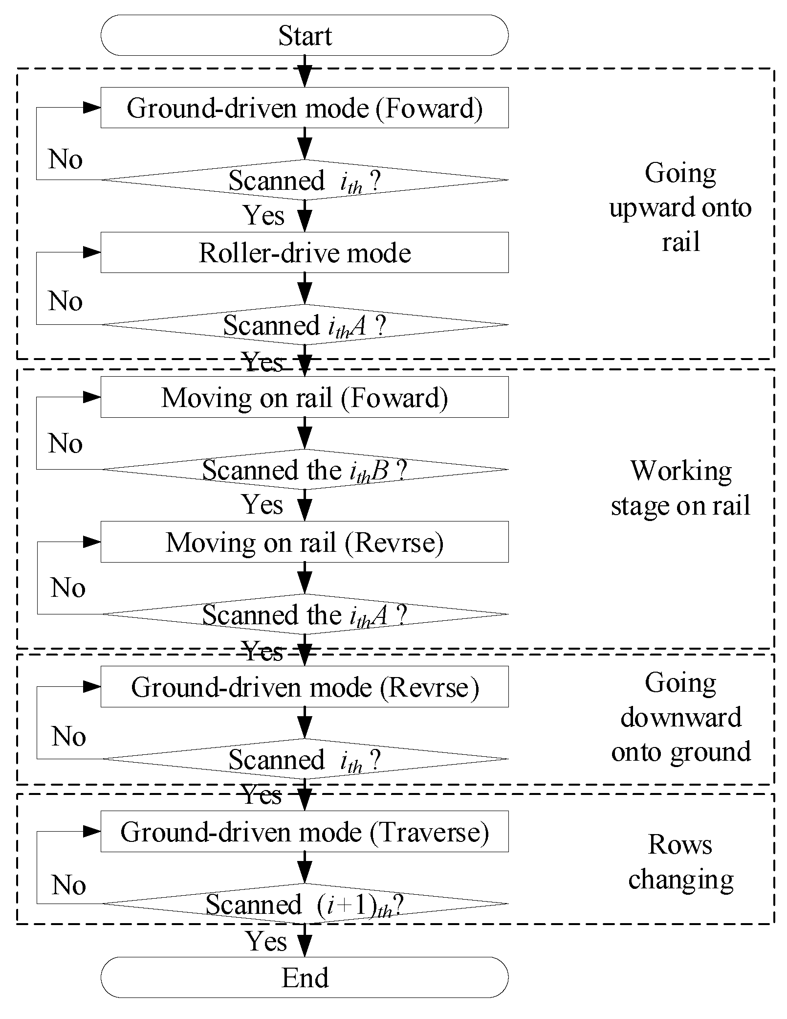
Based on the reasons mentioned above, it is evident that electromagnetic navigation and two-dimensional code positioning are more suitable for the complex environment of a greenhouse. Electromagnetic navigation involves setting magnetic wires under the concrete pavement. However, this method requires the destruction of existing concrete pavement and demands regular maintenance and repair. Furthermore, when the path changes, the wire needs to be relaid. On the other hand, the two-dimensional code-positioning method involves placing it under the rail or on the road surface at the beginning of the rail, as shown in Figure 3. This navigation method’s two-dimensional code can be attached to the beginning of the concrete roadside rail, which is less likely to be damaged. It only requires regular cleaning of dust and debris on the two-dimensional code. As the path changes, the code simply needs to be moved to the specified location, making it a simple and feasible solution. Therefore, this work opts for two-dimensional code-based localization for the vehicle. There are various types of two-dimensional codes, including Data Matrix, MaxiCode, PDF417, and QR Code. The QR Code, a two-dimensional code with fast reflection characteristics, is used for positioning. To improve the success rate and reliability of the vehicle scanning the two-dimensional code, the QR code of each node is duplicated in horizontal and vertical directions. The same two-dimensional code is arranged as shown in Figure 3, ensuring that the vehicle can scan the two-dimensional code even if there is a pose offset in horizontal and vertical directions. Taking the first row as an example, the 0A code is arranged at the front of the rail, the 00 code is arranged on the ground close to the rail, and the 0L and 0R are respectively arranged on the left and right sides of the 00 code for auxiliary positioning.

3.2. Navigation

Figure 4 illustrates that the intelligent vehicle travels between different tube rails to complete transportation. To ensure accurate positioning, the QR code at the front and beginning of each tube rail is scanned twice, while the QR code at the end of the tube rail is scanned once. For example, when the vehicle scans QR code ‘00’ for the first time, it means the vehicle is on the ground and heading towards tube rail No.0. The controller then directs the wheel drive mechanism to move the vehicle forward by the four mecanum wheels. Once the loading rail operation is completed, the QR code scanner obtains the ‘0A’ QR code for the first time, indicating that the vehicle has reached the beginning of tube rail No. 0 and the loading rail operation has been finished. The four mecanum wheels are then suspended, and the rail-driven mode is activated. The vehicle moves towards the end of the tube rail, and upon scanning ‘0B’ for the first time, it indicates that the vehicle has reached the end of tube rail No.0 and needs to execute the rail stop and return action. The roller is rotated in an opposite direction, and after completing the entire tube rail, the vehicle returns to the beginning of the tube rail and scans the ‘0A’ QR code for the second time. This signifies that the vehicle has finished the work on tube rail No. 0 and has reached the beginning of tube rail No.0. The controller then sends the go down tube rail instruction to the wheel drive mechanism. After reaching the end of tube rail, the vehicle scans the No.00 code for the second time, signifying that the vehicle has completed the one tube rail action. The controller sends a horizontal right movement command to the vehicle until it scans the ‘01’ QR code for the first time, and the positioning action of other rails is carried out in the same way. Finally, when the mobile vehicle scans the last tube rail QR code for the second time, the system determines that the vehicle has completed its work and returns. In summary, the intelligent vehicle uses the QR code positioning system to determine its current position and accordingly executes the next action command.

4. Modelling and System Control

4.1. Vehicle Model

The plant-protection vehicle in Figure 5 has an O-rectangular layout for its mecanum wheel mechanism on the chassis. Assuming that the vehicle is running on level ground, the wheel drive mechanism is treated as a rigid body. To analyze the vehicle’s motion, a coordinate system X O Y Z is established with the geometric center of the wheel drive mechanism as its origin O. The motion of the vehicle on the ground is decomposed into three independent components: translation along the x-axis; the y-axis; and rotation about the z-axis. The positive direction along the x-axis is forward, the positive direction along the y-axis is rightward, and the positive direction along the z-axis is counterclockwise. The wheel numbers are indicated in Figure 5.

4.1.1. Kinematics Model

The kinematics of the vehicle can be expressed as follows:
v ¯ X v ¯ Y ω ¯ Z = R 4 1 1 1 1 1 1 1 1 2 ( l X + l Y ) 2 ( l X + l Y ) 2 ( l X + l Y ) 2 ( l X + l Y ) ω 1 ω 2 ω 3 ω 4
The inverse kinematics can be expressed in the following matrix:
ω 1 ω 2 ω 3 ω 4 = 1 R 1 1 ( l X + l Y ) 2 1 1 ( l X + l Y ) 2 1 1 ( l X + l Y ) 2 1 1 ( l X + l Y ) 2 = v ¯ X v ¯ Y ω ¯ Z
where ω 1 is the angular velocity of the mecanum wheel on the front left, ω 2 is the angular velocity of the mecanum wheel on the front right, ω 3 is the angular velocity of the mecanum wheel at the rear left, ω 4 is the angular velocity of the mecanum wheel at the rear right; v ¯ x , v ¯ y , ω ¯ z is the speed of vehicle in the x (horizontal) direction and y (vertical) direction, and the rotation speed in the counterclockwise direction around its geometric center; r is the radius of the mecanum wheel; and l x , l y are the distance from the geometric center of the vehicle to the center of the mecanum wheel in the horizontal and vertical direction.

4.1.2. Dynamics Model

The dynamics of the mobile vehicle is modeled using the Lagrangian method while taking some simplifying assumptions into account. These assumptions include:
  • The vehicle moves on a flat surface, with no potential energy change;
  • The inertia of the mecanum wheel rollers is negligible;
  • The vehicle’s self-coordinate system is situated at its center of gravity.
According to the kinematic equation established by Equation (1), the following can be obtained:
v ¯ x 2 = r 4 × ω 1 + ω 2 ω 3 + ω 4 2 v ¯ y 2 = r 4 × ω 1 + ω 2 + ω 3 + ω 4 2 ω ¯ z 2 = r 4 × 1 l x + l y × ω 1 ω 2 ω 3 + ω 4 2
The kinetic energy E k of vehicle system can be written as
E k = 1 2 m v ¯ x 2 + v ¯ y 2 + 1 2 I z ω ¯ z 2 + 1 2 I ω i = 1 4 ω i 2
where m is the total mass of the plant-protection vehicle; I z is the moment of inertia of the vehicle in z-axis direction; I ω is the moment of inertia of the mecanum wheel; and ω i is the angular velocity of the ith mecanum wheel.
Each mecanum wheel force of the vehicle can be obtained as follows:
T = τ + T g + T f
where T represents the total driving torque of the mecanum wheel; T g is the frictional moment between the mecanum wheel and the ground; and T f is the frictional moment on the shaft when the mecanum wheel rotates. Friction moment T g is the load moment on the mecanum wheel, which is related to the load of vehicle and the friction coefficient μ between the mecanum wheel and the ground. In addition, the weight of the vehicle is distributed to the four mecanum wheels.
T g = μ m g 4 r
The friction torque T f is related to the speed of the mecanum wheel and the axial viscous friction coefficient f of the mecanum wheel, T f = f ω i . There, the following is obtained:
p K T i = τ + μ m g 4 r + f ω
Considering the vehicle system from a single mecanum wheel, the formulas are combined to obtain,
p K T i 1 i 2 i 3 i 4 = m ω 1 ω 2 ω 3 ω 4 + f ω 1 ω 2 ω 3 ω 4 + μ m g r 4 l l l l
where K T is the constant of motor torque and p denotes the pole pairs of brushless DC motors.

4.2. System Control Strategy

After the plant-protection vehicle is powered on, the system is first initialized and the working mode is selected. In remote control mode, the operator controls the vehicle using a remote controller. In automatic mode, the controller receives data from the QR code scanner to determine the vehicle’s current position. Based on this information, the controller generates the next action command, which includes speed control information for the mecanum wheel and the roller. The command is sent to the motor drive mechanism, and the motor is started. The controller uses a closed-loop PID algorithm to control the speed and current, improving the motion accuracy of the vehicle.
A complete workflow intelligent vehicle of can be divided into four stages: moving upward onto the rail, working on the rail, moving toward the ground, and row changing, as depicted in Figure 6. When the scanner scans the QR code with ith at the front of the rail for the first time, it indicates that the vehicle will go upward onto the rail. The mecanum wheels drive the vehicle, and the rollers begin rotating towards the rail. When the vehicle scanner scans the QR code with ith A at the beginning of the rail for the first time, it indicates that the vehicle has completed the action of moving upward onto the rail. The mecanum wheels are stops. The vehicle begin to work on the rail. The QR code ith B located at the end of tube rail indicates the direction in which the vehicle is moving. When the vehicle scanner scans the QR code with ith A for the second time, it means that the vehicle will go downward onto the ground. The rollers continue rotating, and the mecanum wheels start moving downward on the rail. By the time the vehicle scanner scans the QR code ith for the second time, the vehicle has completed the action of going onto the ground. At this point, the plant-protection vehicle stops the rotation of mecanum wheels and rollers. Next, the vehicle moves laterally, starting the rail change operation and entering the next rail to work.

4.3. Vehicle Velocity Control

The vehicular operating environment within a singular rail presents a relatively straightforward control scenario. The primary emphasis of this study lies in the precision of vehicle control when traversing terrestrial surfaces, specifically in the context of facilitating sustainable rail switching. According to the kinematic analysis of mecanum wheel driven mechanism, the vehicle system moving in three directions on the plane depends on the speeds of four mecanum wheels. Therefore, the vehicle platform control can be transformed into the velocity control of each mecanum wheel. The PID algorithm is employed to control the motor’s speed, using the difference between desired and actual speeds as the input value for the controller. The incremental digital PID algorithm is employed for such purposes,
Δ U k = K p E k E k 1 + K I E k + K D E k 2 E k 1 + E k 2
where E ( k ) represents the deviation between the desired and output values; K p represents the proportional gain; K I denotes the integral time constant; and K D signifies the derivative time constant.
Based on the motion equations of the intelligent vehicle, the control output for the vehicle speed is translated into control outputs for each individual mecanum wheel system. The mapping from the speed control input of the vehicle platform to the desired rotational speed of each mecanum wheel motor is demonstrated in the following equation:
u m 1 u m 2 u m 3 u m 4 = 1 R 1 1 ( l X + l Y ) 2 1 1 ( l X + l Y ) 2 1 1 ( l X + l Y ) 2 1 1 ( l X + l Y ) 2 u x u y u ω
where u m i (i = 1, 2, 3, 4) represents the control input for the ith mecanum wheel system. u x , u y , and u w are the output in the x, y, and ω directions.

5. Vehicle Test and Results Analysis

5.1. System Test Environments

In this study, the mobile vehicle was tested under two working conditions: on the rail and on the ground, and the automatic control mode was selected for the vehicle’s movement. Since the vehicle was designed to work on tube rails, the main focus was on its ability to move upward and downward on the rail. Therefore, only one cycle of rail working was tested, with the other cycles expected to be similar to this control. The test results provided the angular velocity of each motor for the mecanum wheel drive, which determines the vehicle’s pose and accuracy of movement on the rail. As for the roller motors, an angular velocity sensor could not be installed due to the roller structure’s limitations, so a current measurement was carried out instead. Each motor-driven mecanum wheel was labeled as front left (FL), front right (FR), back left (BL), and back right (BR), and the vehicle’s movement was realized through the coordination of these four mecanum wheels, as determined by kinematics analysis.

5.2. Results and Analysis

Figure 7 and Figure 8 illustrate the changes in velocity of the mecanum wheels and the current of the motor during the process of vehicle moving up and down the rail. The entire test process was carried out to include the automatic rail change, as well as the two times of moving up and down the rail, as marked in the FL wheel velocity diagram. The analysis process for the velocity change of the other wheels is the same as that of the FL wheel.
As shown in Figure 7, when the vehicle scans the QR code ith for the first time (t = 3 s), it enters the stage of moving upward onto the rail (S1). The vehicle controller sends the command to go upward onto the rail and sets the motor speed to 50 rpm. The FL and BL motors rotate in the opposite direction, while the FR and BR motors rotate in the forward direction. By 5 s, the motor speed reaches 50 rpm and the intelligent vehicle moves straight. After about 2 s, the FL and FR wheels of the vehicle are suspended, while the BL and BR wheels are not yet on the rail, resulting in a large velocity overshoot. After the vehicle scans the two-dimensional code ith A (t = 9 s) under the rail for the first time, it enters the stage of forward driving on the rail (S2), where the entire vehicle is on the rail and all four mecanum wheels are in a suspended state, with all the motors stopped rotating. However, due to control noise and error, the motors still have some residual speed. The vehicle is driven by the roller motor at this point. After operating continuously for about 10 s, the controller sends an instruction for the vehicle to reverse, entering the reverse driving stage on the rail (S3). At this stage, the mecanum wheels are still in a no-load condition on the rail, with a certain speed due to the influence of control noise and error. When the vehicle scans the two-dimensional code ith A (t = 35 s) in the rail for the second time, it enters the stage of moving toward the ground (S4). First, the BL and BR wheels of the vehicle make contact with the ground, followed by the FL and FR wheels.
From Figure 8, it can be observed that the velocity of the BL and BR wheels fluctuates more than the other two wheels, and their driving time is about 1 s longer than that of the FL and FR wheels. When the vehicle scans the ith QR code for the second time (t = 39 s), it completes the moving-toward-the-ground process and begins to move laterally. The transverse movement is completed at t = 44 s, and the vehicle enters the next rail to perform the same workflow. Throughout the whole process, the motor speed is essentially controlled at 50 rpm, and the speed overshoot of the BL and BR wheels is relatively large due to the ground surface not being smooth enough and there being backlash in the transmission systems. The motor current is mostly maintained at around 2.5 A, and the current overshoot is very large. The stability of the wheel speed is mainly ensured during the system control process.
Figure 9 shows the current changes of the roller motor during the mobile vehicle’s movement on the rail. At the beginning of the vehicle’s upward motion onto the rail stage, the roller motor was not rotating, and the driving force of the vehicle was provided by the mecanum wheel. Around 6 s into the process, the roller motor started to rotate, and the vehicle moved steadily on the rail. The driving current at this stage was approximately 5.5 A. After moving forward for about 10 s, the vehicle began to move backward (t = 21 s). As the vehicle scanned the two-dimensional code ith A again, the roller motor stopped rotating, and the vehicle started the downward motion onto the ground stage, which was driven by the mecanum wheel. It can be seen from the figure that the maximum current was about 11 A at the start of the roller, mainly to overcome the inertia force of the vehicle.

6. Conclusions

In this work, an intelligent vehicle was designed for the transportation of crops in a greenhouse. The vehicle is capable of running on both ground and rail in the greenhouse and can automatically change its driving mode between the ground and rail. The mecanum wheel mechanism is used for ground driving, which allows the vehicle to move flexibly. The roller driving mechanism is used for rail driving. The vehicle’s positioning and navigation are achieved using a two-dimensional code system, which is simple and easy to implement without damaging the existing greenhouse environment. The test results demonstrate that the designed intelligent vehicle is capable of performing the functions of moving upward onto the rail, moving toward the ground, rail movement, and automatic rail changing. The system can effectively reduce the labor required for crop transportation in the greenhouse. However, the mecanum wheel is adopted for vehicular propulsion, necessitating the adherence of all four wheels to the ground surface. Nonetheless, the greenhouse corridor’s flooring is composed of concrete, which cannot ensure optimal flat ground. Additionally, as laborers perform their tasks, water accumulation on the ground may occur, leading to deviations in the vehicle’s movement trajectory. Future research will first focus on improving the overall reliability of the vehicle and stabilizing the mecanum wheel driving on uneven terrains.

Author Contributions

Conceptualization, methodology, writing—original draft preparation, and investigation, C.W.; validation, formal analysis, and writing—review and editing, X.T.; and writing—review and editing, supervision, X.X. All authors have read and agreed to the published version of the manuscript.

Funding

This research received no external funding.

Institutional Review Board Statement

Not applicable.

Informed Consent Statement

Not applicable.

Data Availability Statement

Not applicable.

Conflicts of Interest

The authors declare no conflict of interest.

References

  1. Cheng, C.; Fu, J.; Su, H.; Ren, L. Recent Advancements in Agriculture Robots: Benefits and Challenges. Machines 2023, 11, 48. [Google Scholar] [CrossRef]
  2. Bagagiolo, G.; Matranga, G.; Cavallo, E.; Pampuro, N. Greenhouse Robots: Ultimate Solutions to Improve Automation in Protected Cropping Systems—A Review. Sustainability 2022, 14, 6436. [Google Scholar] [CrossRef]
  3. Ullah, I.; Fayaz, M.; Aman, M.; Kim, D. Toward Autonomous Farming—A Novel Scheme Based on Learning to Prediction and Optimization for Smart Greenhouse Environment Control. IEEE Internet Things J. 2022, 9, 25300–25323. [Google Scholar] [CrossRef]
  4. Yang, Q.; Du, X.; Wang, Z.; Meng, Z.; Ma, Z.; Zhang, Q. A Review of Core Agricultural Robot Technologies for Crop Productions. Comput. Electron. Agric. 2023, 206, 107701. [Google Scholar] [CrossRef]
  5. Liu, X.; Hu, Y.; Zhou, G.; Cai, W.; He, M.; Zhan, J.; Hu, Y.; Li, L. DS-MENet for the Classification of Citrus Disease. Front. Plant Sci. 2022, 13, 884464. [Google Scholar] [CrossRef] [PubMed]
  6. Liu, Y.; Hu, Y.; Cai, W.; Zhou, G.; Zhan, J.; Li, L. DCCAM-MRNet: Mixed Residual Connection Network with Dilated Convolution and Coordinate Attention Mechanism for Tomato Disease Identification. Comput. Intell. Neurosci. 2022, 2022, 4848425. [Google Scholar] [CrossRef]
  7. Chen, X.; Zhou, G.; Chen, A.; Yi, J.; Zhang, W.; Hu, Y. Identification of Tomato Leaf Diseases Based on Combination of ABCK-BWTR and B-ARNet. Comput. Electron. Agric. 2020, 178, 105730. [Google Scholar] [CrossRef]
  8. Lv, M.; Zhou, G.; He, M.; Chen, A.; Zhang, W.; Hu, Y. Maize Leaf Disease Identification Based on Feature Enhancement and DMS-Robust Alexnet. IEEE Access 2020, 8, 57952–57966. [Google Scholar] [CrossRef]
  9. Watawana, B.; Isaksson, M. Design and Simulations of a Self-Assembling Autonomous Vertical Farm for Urban Farming. Agriculture 2023, 13, 112. [Google Scholar] [CrossRef]
  10. Kutyrev, A.; Kiktev, N.; Jewiarz, M.; Khort, D.; Smirnov, I.; Zubina, V.; Hutsol, T.; Tomasik, M.; Biliuk, M. Robotic Platform for Horticulture: Assessment Methodology and Increasing the Level of Autonomy. Sensors 2022, 22, 8901. [Google Scholar] [CrossRef]
  11. Tangarife, H.I.; Díaz, A.E. Robotic Applications in the Automation of Agricultural Production under Greenhouse: A Review. In Proceedings of the 2017 IEEE 3rd Colombian Conference on Automatic Control (CCAC), Cartagena, Colombia, 18–20 October 2017; pp. 1–6. [Google Scholar]
  12. Ko, M.H.; Ryuh, B.S.; Kim, K.C.; Suprem, A.; Mahalik, N.P. Autonomous Greenhouse Mobile Robot Driving Strategies from System Integration Perspective: Review and Application. IEEE/ASME Trans. Mechatronics 2014, 20, 1705–1716. [Google Scholar] [CrossRef]
  13. Kondoyanni, M.; Loukatos, D.; Maraveas, C.; Drosos, C.; Arvanitis, K.G. Bio-Inspired Robots and Structures toward Fostering the Modernization of Agriculture. Biomimetics 2022, 7, 69. [Google Scholar] [CrossRef] [PubMed]
  14. Ghobadpour, A.; Monsalve, G.; Cardenas, A.; Mousazadeh, H. Off-Road Electric Vehicles and Autonomous Robots in Agricultural Sector: Trends, Challenges, and Opportunities. Vehicles 2022, 4, 843–864. [Google Scholar] [CrossRef]
  15. Aslan, M.F.; Durdu, A.; Sabanci, K.; Ropelewska, E.; Gültekin, S.S. A Comprehensive Survey of the Recent Studies with UAV for Precision Agriculture in Open Fields and Greenhouses. Appl. Sci. 2022, 12, 1047. [Google Scholar] [CrossRef]
  16. Grimstad, L.; From, P.J. The Thorvald II Agricultural Robotic System. Robotics 2017, 6, 24. [Google Scholar] [CrossRef]
  17. Ye, Y.; Wang, Z.; Jones, D.; He, L.; Taylor, M.E.; Hollinger, G.A.; Zhang, Q. Bin-Dog: A Robotic Platform for Bin Management in Orchards. Robotics 2017, 6, 12. [Google Scholar] [CrossRef]
  18. Li, Y.; Zhou, W.; Song, S.; Qu, J.; Zhou, F.; Guo, K. Design of Experimental Prototype of Flexible Chassis Used in Greenhouse. Trans. Chin. Soc. Agric. Eng. 2017, 33, 41–50. [Google Scholar]
  19. Zhao, Y.; Gong, L.; Liu, C.; Huang, Y. Dual-Arm Robot Design and Testing for Harvesting Tomato in Greenhouse. IFAC-PapersOnLine 2016, 49, 161–165. [Google Scholar] [CrossRef]
  20. Roldán, J.J.; Garcia-Aunon, P.; Garzón, M.; De León, J.; Del Cerro, J.; Barrientos, A. Heterogeneous Multi-Robot System for Mapping Environmental Variables of Greenhouses. Sensors 2016, 16, 1018. [Google Scholar] [CrossRef]
  21. Fei, M.; Wendong, H.; Wu, C.; Sai, W. Design and Experimental Test of Multi-Functional Intelligent Vehicle for Greenhouse. In Proceedings of the 2021 4th IEEE International Conference on Industrial Cyber-Physical Systems (ICPS), Virtual, 10–12 May 2021; pp. 755–760. [Google Scholar]
  22. Ringdahl, O.; Kurtser, P.; Edan, Y. Evaluation of Approach Strategies for Harvesting Robots: Case Study of Sweet Pepper Harvesting. J. Intell. Robot. Syst. 2019, 95, 149–164. [Google Scholar] [CrossRef]
  23. Mousazadeh, H. A Technical Review on Navigation Systems of Agricultural Autonomous Off-Road Vehicles. J. Terramech. 2013, 50, 211–232. [Google Scholar] [CrossRef]
  24. Abanay, A.; Masmoudi, L.; El Ansari, M.; Gonzalez-Jimenez, J.; Moreno, F.A. LIDAR-Based Autonomous Navigation Method for an Agricultural Mobile Robot in Strawberry Greenhouse: AgriEco Robot. AIMS Electron. Electr. Eng. 2022, 6, 317–328. [Google Scholar] [CrossRef]
  25. Jiang, S.; Wang, S.; Yi, Z.; Zhang, M.; Lv, X. Autonomous Navigation System of Greenhouse Mobile Robot Based on 3D Lidar and 2D Lidar SLAM. Front. Plant Sci. 2022, 13, 815218. [Google Scholar] [CrossRef] [PubMed]
  26. Heidari, A.; Parian, J.A. Greenhouse Mobile Robot Navigation Using Wheel Revolution Encoding and Learning Algorithm. J. Agric. Mach. 2021, 11, 1–15. [Google Scholar]
  27. Roldán, J.J.; Cerro, J.; Garzón-Ramos, D.; Garcia-Aunon, P.; Garzón, M.; De León, J.; Barrientos, A. Robots in Agriculture: State of Art and Practical Experiences. In Service Robots; IntechOpen: London, UK, 2018; pp. 67–90. [Google Scholar]
  28. Shiigi, T.; Kondo, N.; Ogawa, Y.; Suzuki, T.; Harshana, H. Temperature Compensation Method Using Base-Station for Spread Spectrum Sound-Based Positioning System in Green House. Eng. Agric. Environ. Food 2017, 10, 233–242. [Google Scholar] [CrossRef]
  29. Yao, L.; Hu, D.; Zhao, C.; Yang, Z.; Zhang, Z. Wireless Positioning and Path Tracking for a Mobile Platform in Greenhouse. Int. J. Agric. Biol. Eng. 2021, 14, 216–223. [Google Scholar] [CrossRef]
  30. Saike, J.; Meina, Z.; Xue, L.; Yannan, Q.; Xiaolan, L. Development of Navigation and Control Technology for Autonomous Mobile Equipment in Greenhouses. J. Chin. Agric. Mech. 2022, 43, 159. [Google Scholar]
  31. Long, Z.; Xiang, Y.; Lei, X.; Li, Y.; Hu, Z.; Dai, X. Integrated Indoor Positioning System of Greenhouse Robot Based on UWB/IMU/ODOM/LIDAR. Sensors 2022, 22, 4819. [Google Scholar] [CrossRef]
  32. Yang, L.J.; Pitla, S.; Yang, Z.D.; Xia, P.P.; Zhao, C.Y. Path Tracking of Mobile Platform in Agricultural Facilities Based on Ultra Wideband Wireless Positioning. Trans. CSAE 2019, 35, 17–24. [Google Scholar]
  33. Chen, W.H.; You, F. Semiclosed Greenhouse Climate Control under Uncertainty via Machine Learning and Data-Driven Robust Model Predictive Control. IEEE Trans. Control Syst. Technol. 2022, 30, 1186–1197. [Google Scholar] [CrossRef]
  34. Gat, G.; Gan-Mor, S.; Degani, A. Stable and Robust Vehicle Steering Control Using an Overhead Guide in Greenhouse Tasks. Comput. Electron. Agric. 2016, 121, 234–244. [Google Scholar] [CrossRef]
  35. Yuan, Z.; Tian, Y.; Yin, Y.; Wang, S.; Liu, J.; Wu, L. Trajectory Tracking Control of a Four Mecanum Wheeled Mobile Platform: An Extended State Observer-Based Sliding Mode Approach. IET Control Theory Appl. 2020, 14, 415–426. [Google Scholar] [CrossRef]
  36. Li, Y.; Zhang, H.; Liang, X.; Huang, B. Event-Triggered-Based Distributed Cooperative Energy Management for Multienergy Systems. IEEE Trans. Ind. Inform. 2019, 15, 2008–2022. [Google Scholar] [CrossRef]
  37. Nguyen, A.T.; Rath, J.; Guerra, T.M.; Palhares, R.; Zhang, H. Robust Set-Invariance Based Fuzzy Output Tracking Control for Vehicle Autonomous Driving under Uncertain Lateral Forces and Steering Constraints. IEEE Trans. Intell. Transp. Syst. 2020, 22, 5849–5860. [Google Scholar] [CrossRef]
  38. Henten, E.J.; Hemming, J.; Tuijl, B.A.J.; Kornet, J.; Meuleman, J.; Bontsema, J.; Os, E.A. An Autonomous Robot for Harvesting Cucumbers in Greenhouses. Auton. Robot. 2002, 13, 241–258. [Google Scholar] [CrossRef]
  39. Singh, S.; Burks, T.F.; Lee, W.S. Autonomous Robotic Vehicle Development for Greenhouse Spraying. Trans. ASAE 2005, 48, 2355–2361. [Google Scholar] [CrossRef]
  40. Masoudi, H.; Alimardani, R.; Omid, M.; Mohtasebi, S.S.; Bagheri, S.S. Design, Fabrication and Evaluation of a Mobile Robot for Spraying in Greenhouses. J. Agric. Eng. Res. 2011, 12, 87–100. [Google Scholar]
  41. Sánchez-Hermosilla, J.; González, R.; Rodríguez, F.; Donaire, J.G. Mechatronic Description of a Laser Autoguided Vehicle for Greenhouse Operations. Sensors 2013, 13, 769–784. [Google Scholar] [CrossRef]
  42. Gázquez, J.A.; Castellano, N.N.; Manzano-Agugliaro, F. Intelligent Low Cost Telecontrol System for Agricultural Vehicles in Harmful Environments. J. Clean. Prod. 2016, 113, 204–215. [Google Scholar] [CrossRef]
  43. Sharifi, M.; Young, M.S.; Chen, X.; Clucas, D.; Pretty, C. Mechatronic Design and Development of a Non-Holonomic Omnidirectional Mobile Robot for Automation of Primary Production. Cogent Eng. 2016, 3, 1250431. [Google Scholar] [CrossRef]
  44. Cantelli, L.; Bonaccorso, F.; Longo, D.; Melita, C.D.; Schillaci, G.; Muscato, G. A Small Versatile Electrical Robot for Autonomous Spraying in Agriculture. AgriEngineering 2019, 1, 391–402. [Google Scholar] [CrossRef]
  45. Heravi, A.; Ahmad, D.; Hameed, I.A.; Ramin Shamshiri, R.; Balasundram, S.K.; Yamin, M. Development of a Field Robot Platform for Mechanical Weed Control in Greenhouse Cultivation of Cucumber. In Agricultural Robots—Fundamentals and Applications; Zhou, J., Zhang, B., Eds.; IntechOpen: London, UK, 2019. [Google Scholar] [CrossRef]
  46. Mosalanejad, H.; Minaei, S.; Borghei, A.; Farzaneh, B. Evaluation of Navigation System of a Robot Designed for Greenhouse Spraying. Int. J. Smart Sens. Intell. Syst. 2020, 13, 1. [Google Scholar] [CrossRef]
  47. Xiong, Y.; Ge, Y.; Grimstad, L.; From, P.J. An Autonomous Strawberry-Harvesting Robot: Design, Development, Integration, and Field Evaluation. J. Field Robot. 2020, 37, 202–224. [Google Scholar] [CrossRef]
  48. Baek, E.T.; Im, D.Y. ROS-Based Unmanned Mobile Robot Platform for Agriculture. Appl. Sci. 2022, 12, 4335. [Google Scholar] [CrossRef]
  49. Su, L.; Liu, R.; Liu, K.; Li, K.; Liu, L.; Shi, Y. Greenhouse Tomato Picking Robot Chassis. Agriculture 2023, 13, 532. [Google Scholar] [CrossRef]
  50. Zhao, Y.; Zhang, C.; Ni, Y.; He, S.; Wen, X. Development of Multifunctional Greenhouse Agricultural Robot. In Proceedings of the 2019 2nd International Conference on Informatics, Control and Automation (ICA 2019), Hangzhou, China, 26–27 May 2019; pp. 181–186. [Google Scholar] [CrossRef]
Figure 1. Overall diagram of the vehicle.
Agriculture 13 01020 g001
Figure 2. Chassis design of the intelligent vehicle.
Agriculture 13 01020 g002
Figure 3. Diagram of the two-dimensional code localization.
Agriculture 13 01020 g003
Figure 4. Schematic diagram of vehicle positioning and navigation in the greenhouse.
Agriculture 13 01020 g004
Figure 5. Diagram of vehicle kinematics.
Agriculture 13 01020 g005
Figure 6. The intelligent vehicle working strategy.
Agriculture 13 01020 g006
Figure 7. Velocity variation of mecanum wheels.
Agriculture 13 01020 g007
Figure 8. Current variation of mecanum wheel motors.
Agriculture 13 01020 g008
Figure 9. Current variation of roller motor.
Agriculture 13 01020 g009
Table 1. Different vehicles used in greenhouse.
YearReferenceMobilityTerrainRows Switching
2002[38]2WDRailManual
2005[39]6WDSand and concreteAutomatic
2011[40]3WDConcreteAutomatic
2013[41]4WDSandAutomatic
2016[42]TrackEarthManual
2016[43]4WD4SEarthAutomatic
2017[18]4WD4SEarthAutomatic
2019[44]TrackEarthAutomatic
2019[45]1WDMonorailRail-guided
2019[22]2WDRailRail-guided
2020[46]2WDConcreteAutomatic
2020[47]4WD4SSandAutomatic
2021[26]4WD4SEarth/ConcreteAutomatic
2021[24]4WDEarthAutomatic
2022[48]2WDConcrete and railAutomatic
2022[10]2WDEarthAutomatic
2023[49]4WDPlastic woven meshAutomatic
Table 2. Requirement of the designed intelligent vehicle.
ItemsUnitRequirements
Maximum rated loadkg100
Speed on the groundm/s 0.5
Working speed on railm/s 0.5
Non-working speed on railm/s1
Change between rail and rail-Automatic
Change between rail and ground-Automatic
Disclaimer/Publisher’s Note: The statements, opinions and data contained in all publications are solely those of the individual author(s) and contributor(s) and not of MDPI and/or the editor(s). MDPI and/or the editor(s) disclaim responsibility for any injury to people or property resulting from any ideas, methods, instructions or products referred to in the content.

