Article

Analysis of Rollover Characteristics of a 12 kW Automatic Onion Transplanter to Reduce Stability Hazards

1
Agricultural Technical Institute, Division of Horticultural Technologies, Ohio State University, Wooster, OH 44691, USA
2
Department of Agricultural Machinery Engineering, Graduate School, Chungnam National University, Daejeon 34134, Republic of Korea
3
Department of Smart Agricultural Systems, Graduate School, Chungnam National University, Daejeon 34134, Republic of Korea
4
Department of Agricultural and Industrial Engineering, Hajee Mohammad Danesh Science and Technology University, Dinajpur 5200, Bangladesh
5
TYM Co., Ltd., Iksan 54576, Republic of Korea
6
National Institute of Agricultural Science, RDA, Jeonju 54875, Republic of Korea
*
Author to whom correspondence should be addressed.
Agriculture 2023, 13(3), 652; https://doi.org/10.3390/agriculture13030652
Submission received: 20 February 2023 / Revised: 9 March 2023 / Accepted: 9 March 2023 / Published: 10 March 2023

Abstract

:
The rollover tendency of upland farm machinery needs to be carefully considered because upland crop fields are typically irregular, and accidents frequently result in injuries and even death to the operators. In this study, the rollover characteristics of an underdeveloped 12 kW automatic onion transplanter were determined theoretically and evaluated through simulation and validation tests considering the mounting position of the transplanting unit and load conditions. The center of gravity (CG) coordinates for different mass distributions, and static and dynamic rollover angles were calculated theoretically. Simulation and validation tests were conducted to assess the static rollover angle under different mounting positions of the transplanting unit and load conditions of the onion transplanter. The dynamic rollover tendency was evaluated by operating the onion transplanter on different surfaces and at different speeds. According to the physical properties and mass of the onion transplanter, the theoretical rollover angle was 34.5°, and the coordinates of the CG gradually moved back to the rear wheel axle after attaching the transplanting part and under upward riding conditions. The average simulated rollover angle was 43.9°. A turning difference of 4.5° was observed between the right and left sides, where a 3° angle difference occurred due to the load variation. During the dynamic stability test, angle variations of 2~4° and 3~6° were recorded for both high and low driving speeds in the vehicle platform and transplanting unit, respectively. The overturning angles also satisfied the ISO standard. This study provides helpful information for ensuring the safety of upland crop machinery operating under rough and sloped field conditions.

1. Introduction

The onion (Allium cepa L.) is the world’s second most consumed and widely cultivated horticultural crop, after the tomato [1]. It contains various phytochemicals, such as organosulfur and phenolic compounds, polysaccharides, saponins, minerals, and antioxidants, which are significant components of the Mediterranean diet, play vital roles in improving human health, and minimize a variety of diseases [2,3,4,5]. The global onion cultivation area has increased by more than 3 million ha from 1990 to 2019, and annual world production was around 97 million tons in 2019 [6]. However, the cultivation rate of onions is decreasing in many countries due to agricultural labor shortages, the aging of the farmers, the increasing cost of labor, and the low mechanization rate of upland crop production systems. Onion farming typically requires between 185 and 260 person-hours per hectare, which is both inefficient and labor-intensive [7]. In order to overcome this drawback, semi-automated and automated transplanters are becoming popular. In semi-automated transplanters, onion seedlings are picked and fed manually, but they are transplanted mechanically. Contrarily, the onion seedlings are picked, fed, and transplanted in synchronized sequences by automated transplanters. Autonomous transplanters can be riding-type or walking-type. Moreover, advanced technologies, such as laser radar, vision systems, and 3S systems integrated with artificial intelligence (i.e., machine vision, deep learning) are currently emerging for improving the accuracy and efficiency of both the unmanned and human–machine cooperative operations of upland crop machinery [8,9,10]. Usually, upland crop transplanters require high clearance as most of the upland crops are transplanted in raised beds. This high clearance sometimes makes the vehicle unstable and results in a rollover [11].
Among the basic considerations during upland crop machinery development, such as power requirement analysis, gearbox optimization, torque calculation, the stress and fatigue determination of major components, and vibration assessment, stability analysis is one of the essential issues to avoid accidents during operations in the field, along with the operator’s safety assurance [12,13,14,15,16,17,18,19]. The rollover tendency of upland farm machinery needs to be considered with importance because upland crop (i.e., onion, garlic, cabbage, radish, or carrot) fields are typically irregular and sometimes very inclined. This frequently results in accidents, injuries, and even the death of the operators [20]. These rollover-related farming incidents account for a sizable fraction of agricultural machinery-related fatalities. For example, 70% of deaths in fatal agricultural accidents in Spain are caused by tractors overturning. In Turkey, 34.1% of farm accidents occur due to the sideways and backward motions of the tractor overturning. Similarly, 32% of fatalities and 6% of non-fatal injuries are caused by overturning in the United States [21]. The stability of the onion transplanter dictates its rollover possibility, which is influenced by the transplanter’s static, dynamic, and operational characteristics. The static and dynamic characteristics include wheelbase, tread width, and center of gravity, while the operating parameters include operational speed, turning radius, land inclination, and surface roughness [22,23].
The lateral and longitudinal rollover tendencies of any agricultural vehicle can be determined by calculating the center of gravity (CG) and stability angles theoretically or by measuring the rollover angle physically. The physical parameters of the machine influence the CG, and the rollover angle depends on the vertical height of the CG [24,25]. The vertical height can be measured using the axle lifting technique, in which the front axle is elevated. The vertical height is estimated using the vehicle’s mass transfer between the front and rear axles [22]. Around 44,000 agricultural machinery accidents were recorded in 2021 in South Korea, where around 11,000 (26%) were rollover-related [26]. According to the Korean Ministry of Environment [27], 23.6% of agricultural land in South Korea has slope angles of 8.5° or more. Driving in those fields increases the possibility of lateral and longitudinal rollover. The dynamic stability of any vehicle is critical for defining the balance function during field operations. Most of the failures are due to either the sudden motion of the base of support or the sudden acceleration of the center of mass of the vehicle. Dynamic stability can be easily determined from the static stability angles and slope of the operating field [28,29,30]. Angle sensors can be used to monitor dynamic instability in real time. Based on the types of agricultural machinery, the required static stability angles vary from 15° to 45° [22]. To decrease the rollover hazards and maintain the optimum efficiency of agricultural machinery, every country recommends a specific slop limit based on the type of field operation. For example, Korea allows a 15° slop limit for tractor-attached four-wheel baler systems, a 12° slop for plough operation, and 10° for tillage operation with obstacle passing in the uplands [27]. In Japan, 8–10° slop is allowed for forage crops that do not require management work; 10–15° slop is recommended for grasslands for hay; and pastures receive gradients of more than 15° [31]. Most countries have enacted legislation to ensure proper agricultural machinery operation and to minimize machinery-related fatalities.
As the fatality rate of rollover incidents is greater than that of other forms of off-road agricultural vehicle hazards, the determination of the static and dynamic rollover characteristics of off-road agricultural vehicles and farm machinery is essential to minimize agricultural work-related fatalities, especially when the vehicle is under development conditions. A 12 kW self-propelled riding-type automatic onion transplanter is under development in this study. Therefore, the objective of this study was to evaluate the rollover characteristics (static and dynamic stability) of the onion transplanter through simulation and validation tests considering the mounted position of the transplanting unit and load conditions.

2. Materials and Methods

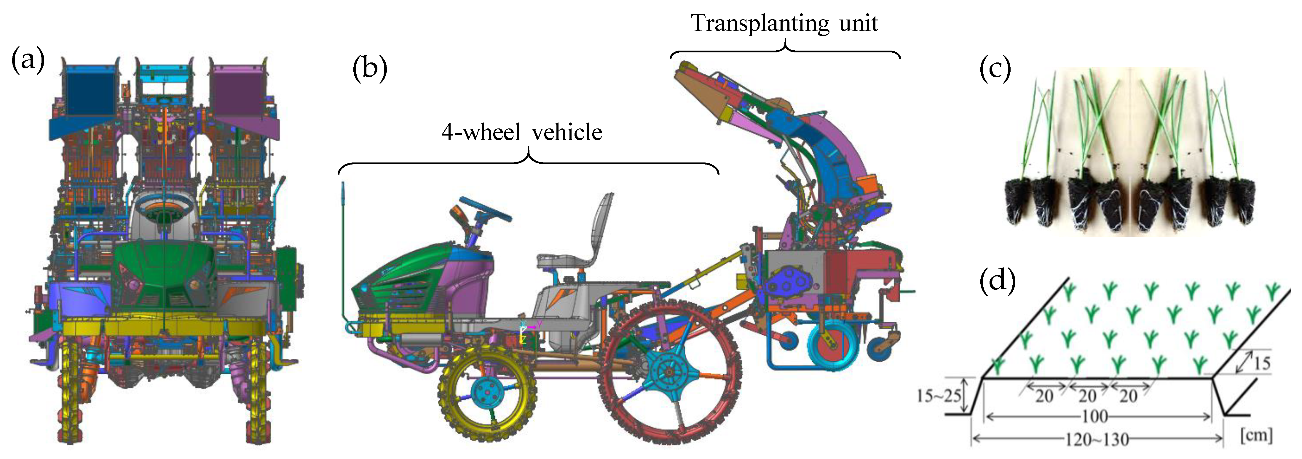
2.1. An Overview of the Underdeveloped Onion Transplanter

A three-dimensional model of the considered onion transplanter is shown in Figure 1a,b. It is a combination of two main units: a 12 kW self-propelled riding-type four-wheel vehicle and an onion transplanting system. The physical features of the prototype onion transplanter are listed in Table 1. The whole transplanting activity is also a combination of three major processes (mechanisms): (a) seedling picking (extraction mechanism), (b) supply (conveying mechanism), and (c) dibbling (planting mechanisms). The onion cell trays were initially placed in the seedling trays. The onion seedlings (Figure 1c) are retrieved from the growing cell seedling tray and placed on the conveyor belts using the pushing rods. Seedlings were transported into the planting hopper by the conveyor mechanism and implanted in six rows according to the seedling planting mechanisms. All of these units are sequentially interlinked. A total of three individual units run together and transplant six seedlings in a row. Finally, two axillary pressing wheels (a total of twelve for six rows) squeeze the earth to keep the seedlings upright and the mulch layer from being damaged. Figure 1d shows the transplanting pattern with dimensions.
The power source (12 kW engine) of the transplanter was attached to the front side of the 4-wheel vehicle; as a result, the front wheels carried most of the vehicle load. When the transplanting unit was hitched to the 4-wheel vehicle, the mass distribution shifted in the opposite direction. Usually, self-propelled, lightweight farm machinery is recommended to use a fixed axle, counterbalance, and tilth to ensure adequate wheel–ground contact during field operations. In this transplanter, the transplanting unit mainly worked as a counterbalance. The weight of the engine, on the other hand, had a significant impact on maintaining uniform contact between the wheels and the operating surface. Several factors of the operating surface, such as uphill and downhill roads, sudden direction changes, steep slopes, or obstacles, cause a rollover. The possibility of rollover can also be determined by calculating the velocity and acceleration range of the transplanter CG, which meets a set of dynamics requirements [32]. The higher velocity limit is used to express dynamic stability, and the acceleration limit at zero speed is used to express static stability.

2.2. Stability Factors Influencing Rollover Severity

There are several ISO standards for evaluating vehicle rollover characteristics in order to achieve stable driving and avoid losing control during operations. ISO 789-6 [33] defines a traditional method of determining the height of the CG using the axle lift method and ascribing board, which are used to compute the static stability angles of tractors. ISO 16251-2 [34] is the updated approach for computing the CG and static stability angles of self-propelled agricultural machinery using the same axle lift method. This ISO standard also suggests counting the weight shift trends by moving fluids from the vehicles. However, several studies, including those by Khorsandi et al. [35] and Wang et al. [36], found no significant effect of this weight-shifting trend. As carrying load significantly affects the position of CG, resulting in a change in stability angle, ANSI/OPEI B71.9 [37] emphasizes the load conditions during the evaluation of the static stability of multipurpose off-highway utility vehicles. It recommends considering two load conditions: (a) the vehicle with operator and passenger loads, (b) the maximum allowable total load mentioned by the manufacturer. The lateral stability angles should not exceed 33° and 24°, respectively, whereas the longitudinal static stability limit is 28° for both conditions. Similarly, ANSI/OPEI B71.4 [38] highlights the attached lawn care equipment. With and without considering the weight of attachments, the lateral and longitudinal rollover angle limits are 25° and 30° for both conditions, respectively. Moreover, the safety factors of standard and narrow-track tractors are addressed by ANSI/ASABE AD26322-1 [39] and ANSI/ASABE AD26322-2 [40]. Safety for agricultural field equipment and the balancing angle of all-terrain vehicles are defined under ANSI/ASAE S318.18 [41] and ANSI/SVIA 1, respectively. ANSI/ASAE S318.18 does not report the stability angles directly, whereas ANSI/SVIA 1 introduces a pitch stability coefficient (Kp), which should be greater than 1. However, the age and gender of the drivers; the types, weight, and age of the vehicle; and the driving time (day or night) are the factors that affect the injury severity of the drivers during stability-related accidents [42,43].

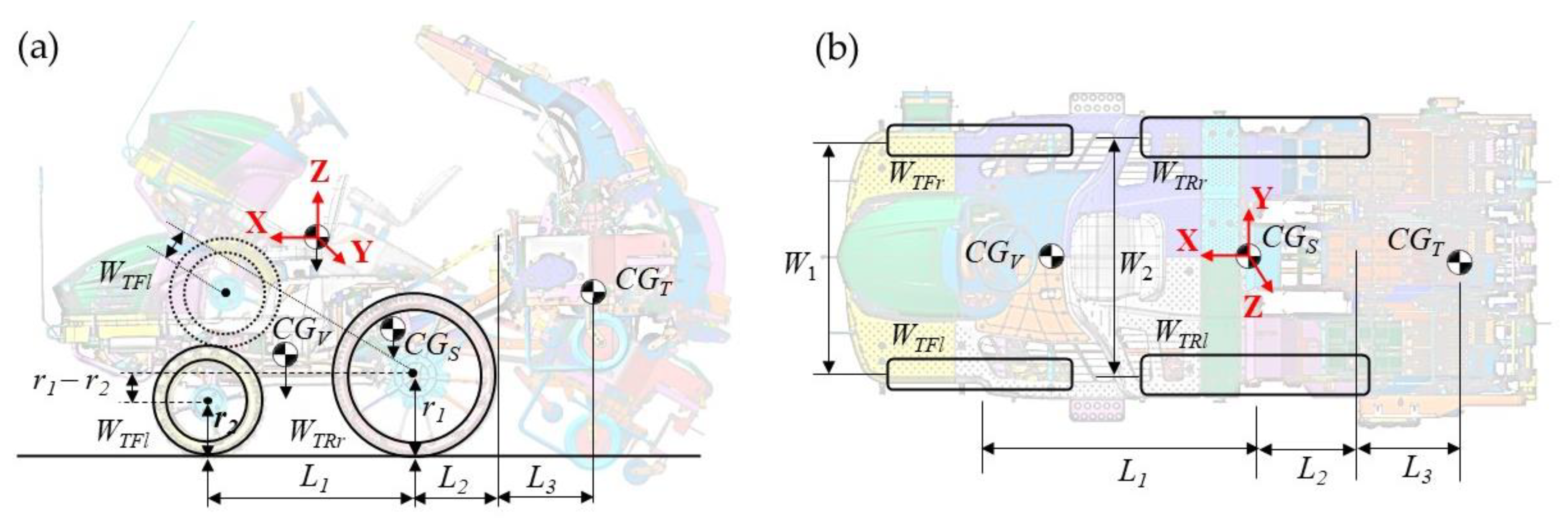
2.3. Determination of Center of Gravity Coordinates by Mass Distribution

A rollover incident is a major hazardous factor that directly affects the operator’s safety. There are two major types of rollovers: tripped (caused by forces from an external object) and untripped (due to the changes in CG) [44]. Although most road vehicle rollovers are tripped rollovers, the percentage of tripping rollovers in agricultural vehicles is comparatively lower, so this study concentrated on untripped rollovers due to steering input, speed, and friction with the ground. The rollover analysis includes calculating the CG coordinates, estimating the transverse rollover angle, and simulating and validating the static or dynamic stability. The center of gravity (CG) is an imaginary point through which the entire mass of an object acts. Figure 2 shows a schematic diagram of the transference of the CG of the onion transplanter. At first, the CG of the four-wheel vehicle (CGV) was calculated. Then, the CG of the whole transplanter (CGT) was calculated considering different load statuses under normal and front axle lifted conditions. The onion transplanter’s reference CG coordinates (X0, Y0, Z0: 0, 0, 0 mm) were assumed to have an origin at the ground point of the rear wheel axle. The front wheel direction of the transplanter indicated the (+) displacement on the X-axis, while the rear wheel direction represented the (−) displacement. Similarly, the right- and left-side of the transplanter indicated the (+) displacement and (−) displacement, respectively, on the Y-axis. Furthermore, on the Z axis, the upper direction represented the (+) displacement, while the ground direction indicated the (−) displacement. The CG coordinates of the vehicle (CGV: XV, YV, ZV) and whole transplanter (CGT: XT, YT, ZT) were calculated using Equations (1)–(3) and (4)–(6), respectively, following ISO 16231-2 [33] and methods of previous studies [20,24,25]. The required physical properties and masses acting on the four wheels of the transplanter for calculating the CG coordinates were mentioned in Table 1. Additionally, δ indicates the tilt angle.
X V = ( ( W V F l + W VFr ) × L 1 )   /   W V
Y V = X V   × cot δ ( W V F l   2 × ( L 1 × cos δ + ( r 1 r 2 ) × sin δ ) ) ÷ W V × sin δ
Z V = ( W V R l × W V R r + W V F l × ( W 1 + W 2 ) / 2 + W V F r × ( W 1 + W 2 ) / 2 )   / W V
X T = ( ( W T F l + W T F r ) × L 1 )   /   W T
Y T = X T   × cot δ ( W T F l × ( L 1 × cos δ + ( r 1 r 2 ) × sin δ ) ) ÷ W T × sin δ
Z T = ( W T R l × W T R r + W T F l × ( W 1 + W 2 ) / 2 + W T F r × ( W 1 + W 2 ) / 2 )   / W T

2.4. Static Stability Analysis

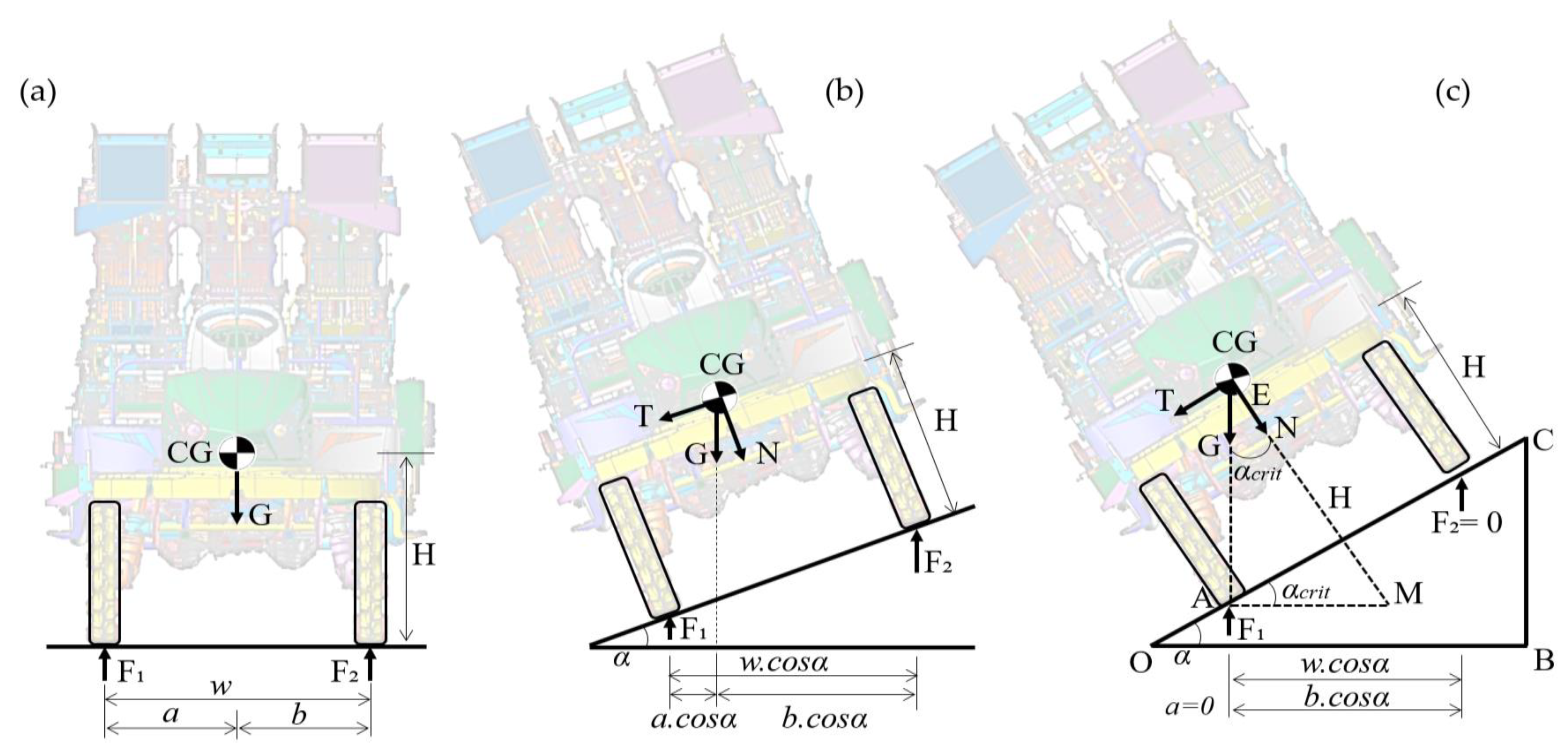
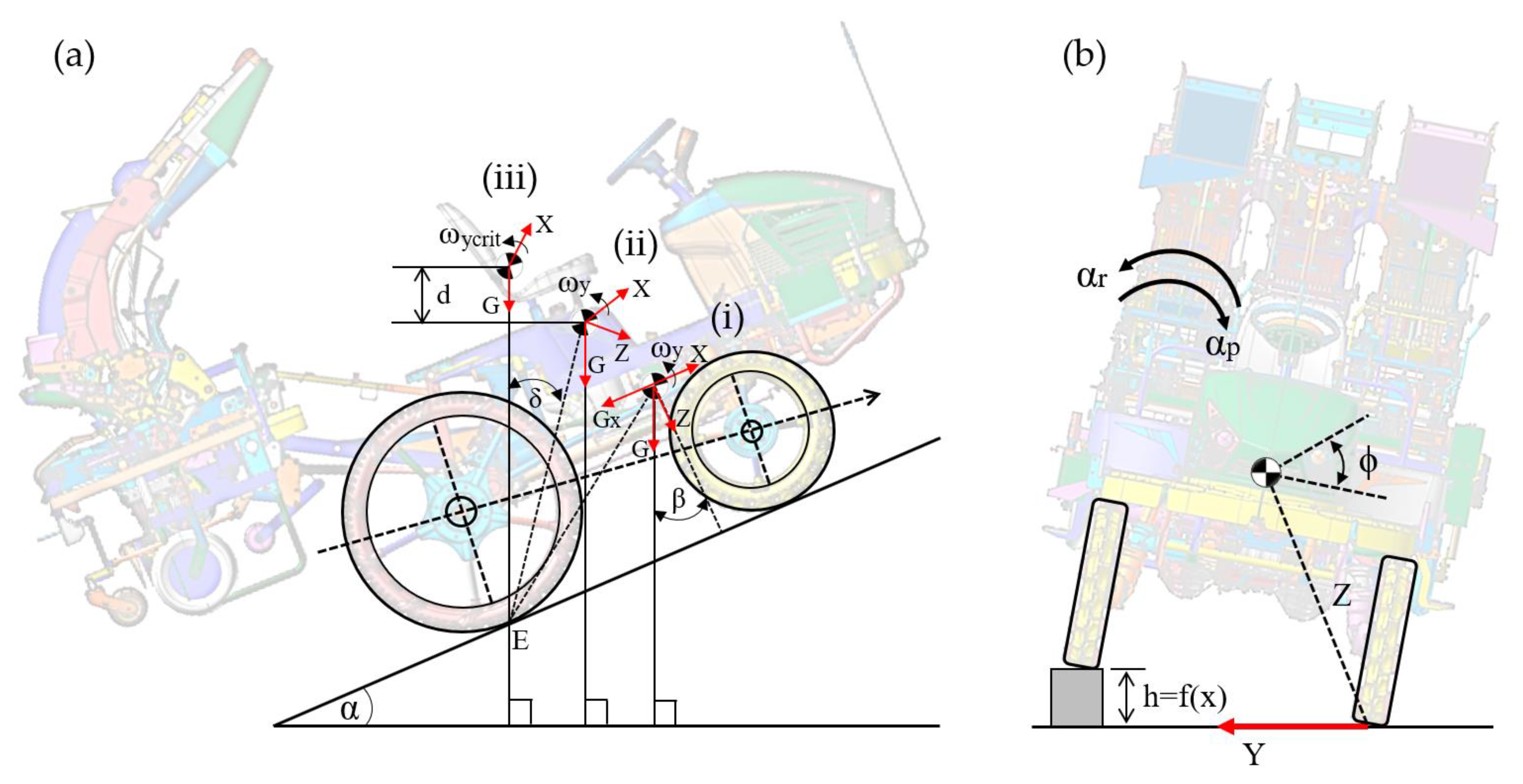
2.4.1. Theoretical Rollover under Static Conditions

According to the road and off-road vehicle system dynamic [23,28,29,30], a rollover is one kind of vehicle incident where the vehicle tips over in its lateral or longitudinal direction. A static rollover occurs due to the transference of CG, and the CG is related to the mass of the vehicle. If the mass of the considered onion transplanter is mt on a horizontal surface and acting through the CG, considering the gravitational constant (g), the mass force of the onion transplanter will be G = mtg. Let F1 and F2 be the ground reaction forces on the right- and left-sided wheels of the vehicle, H be the vertical distance from CG to the ground, and w be the wheel track, as shown in Figure 3a. Equations (7) and (8) explain the relationship between G and the reaction forces operating on the wheels.
F 1 + F 2 = G
F 2 w c o s α = G a
According to Figure 3a, a and b represent the horizontal distance of the CG from the left and right rear wheels, respectively. When the tilt-table (flat surface) begins to tilt, the reaction force F2 decreases gradually with the rising tilting angle (α). As shown in Figure 3b, the resultant force of G, a and b will change at the same time, and two components of G (transversal force T and ground response force N) will be induced. However, b grows and a drops from the initial circumstances, and the onion transplanter remains stable in that situation. The influence of internal fluid (fuel and lubricant) movement was not considered in this calculation. The gradual increment of α, as shown in Figure 3c, causes F2 and a to be zero at some point. This condition and relevant angle can be defined as critical condition and critical angle (αcrit), respectively. Equations (9) and (10) can be used to calculate this angle based on the ∆AEH. According to the road vehicle dynamics, w/(2H) is called Static Stability Factor (SSF) or Rollover Threshold (RT).
t a n α c r i t = T N
α c r i t = t a n 1 w 2 H
The onion transplanter will rollover laterally if the tilting angle is larger than the critical angle. Otherwise, it will stay the same. If the acting direction of CG exceeds the wheel track, the onion transplanter will roll over in the lateral direction. Similarly, longitudinal rollover will occur when the acting direction of the CG exceeds the wheelbase.

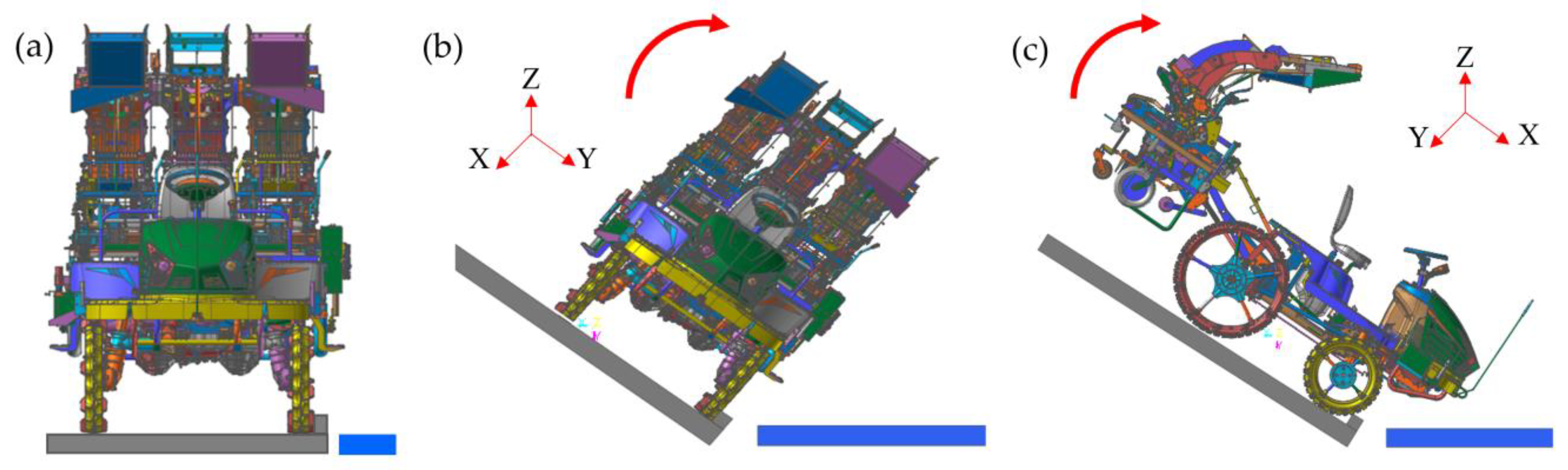
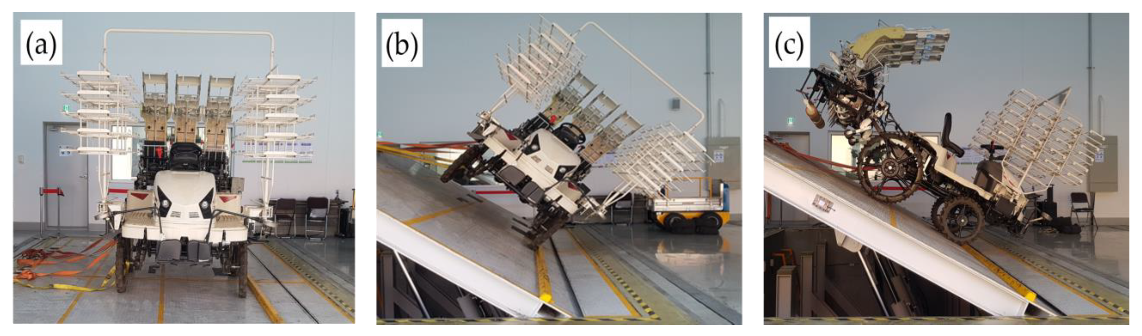
2.4.2. Simulation and Validation under Static Conditions

Simulation provides valuable solutions by giving clear insights into complex systems instead of testing the initial prototype or system physically. It solves real-world problems safely and efficiently. In this study, a simulation was also carried out to determine the static rollover characteristics of the onion transplanter using commercial software (Recurdyn V9R4, FunctionBay, Gyeonggi-do, Republic of Korea) considering the different mounting positions of the transplanting unit and load conditions. A three-dimensional model of the developed onion transplanter was provided by the manufacturer, which was prepared using the SolidWorks software and imported into Recurdyne for simulation purposes. The seedling carrying racks were not included in the 3D model; however, relevant weight was added at the specific point during simulation. All the required properties were defined in the Recurdyn software before initiating the simulation. Figure 4 shows the simulation steps for determining the static (lateral and longitudinal) rollover angles.
Validation refers to the process of confirming that the simulation achieved its intended goals. For any simulation model that is to be used in actual application, it is essential to validate the model insofar as practicable, since real decisions are going to be made based on the validation outcomes. In this study, the static rollovers (lateral and longitudinal) were validated at the Korean Agricultural Technology Promotion Agency, Iksan, Republic of Korea, as shown in Figure 5. Additional weight bags were used instead of the operator and load of the seedling trays. Three replications were applied, and the values were averaged.

2.5. Dynamic Stability Analysis

2.5.1. Theoretical Rollover under Dynamic

According to the road and off-road vehicle system dynamic [23,28,29,30], the tendency of any off-road vehicle to roll over, slip, or lose contact with the ground, exceeding the static equilibrium in a motion condition, is referred to as its dynamic stability. In this study, the dynamic rollover possibility of the onion transplanter was determined following the model of Rédl et al. [45]. If the transplanter is operated on a one-sided uphill path and the kinetic energy related to the contact point of the downhill wheel exceeds the potential energy of CG displacement, the transplanter will roll over. The vertical reaction forces of the downhill wheels (E) play a vital role in this condition. Figure 3 shows the mass components (Gx, Gz) of the transplanter in the slope’s starting position. The rollover possibility will begin with the uphill wheels’ angular rotational trajectory centering the downhill wheels. Equation (11) expresses the relationship between the resulting mass vector and the mass components.
G = G x 2 + G z 2
Equation (12) was used to calculate the direction of the resulting mass vector with respect to the transplanter’s Z-axis, and Equation (13) was used to calculate the coefficient of stability for this particular circumstance.
x = t a n 1 G x G z
ξ = π 2 t a n 1 G x G z x
Even in the static state, the transplanter will roll over if the value of ξ falls below 1. The CG approaches backward on a curving route under the stable condition, but the ξ value remains 1 until the transplanter rolls over, as shown in positions (i) and (ii) of Figure 6a. During this action, the CG goes rearward with respect to point E, following a radius that can be computed using Equation (14).
E C G ¯ = G z 2 + X r 2
The CG moves rearward (e.g., from position (ii) to (iii)) when the onion transplanter rolls over with regard to point E. The kinetic energy of the transplanter in position (ii) is the sum of the concentrated kinetic energy, the kinetic energy for rotation, and the rotational motion of the transplanter’s CG with respect to point E. Equation (15) was used to explain this condition numerically, where 9.8 represents the gravitational constant (g). Similarly, Equation (16) was used to calculate the angular velocity of the transplanter with reference to the Z-axis for position (ii) of the CG.
K E = 1 2 ω y 2 × ( J y + 0.98 G × E C G 2 ¯ )
ω y = 2 K E J y + 0.98 G × E C G 2 ¯
While the CG moves from position (ii) to (iii), an angle is formed between the two places with regard to point E, which was calculated using Equation (17). Moreover, a certain amount of potential energy is gained, which can be represented using Equation (18).
δ = c o s 1 ( K E G + E C G ¯ + c o s ( π 2 β γ ) )
P E = G × E C G ¯ ( 1 sin ( β + δ ) )
The kinetic energy will be higher or equal to the obtained potential energy in this condition, which may cause the onion transplanter to roll over under the dynamic situation. Equation (19) expresses the angular velocity at this position as the critical angular velocity.
ω y c r i t = 2 P E J y + 0.98 G × E C G 2 ¯
If the condition ωyωycrit is met while operating on an uphill slope, the onion transplanter may roll over at any CG position. The same method can be used to determine the rollover possibility of the onion transplanter when operating on a downhill surface.
During driving, any wheel of the onion transplanter may come into contact with incompressible impediments. Ahmadi [40] developed a model to determine the rollover angle in this situation. Figure 6b shows the transplanter’s rolling and pitching velocity and acceleration under this circumstance. The physical properties of the obstacle can be defined by the h = f(x) function. The critical height of the CG caused by the obstacle can be calculated using Equation (20).
h c r i t = w 2 4 + H 2

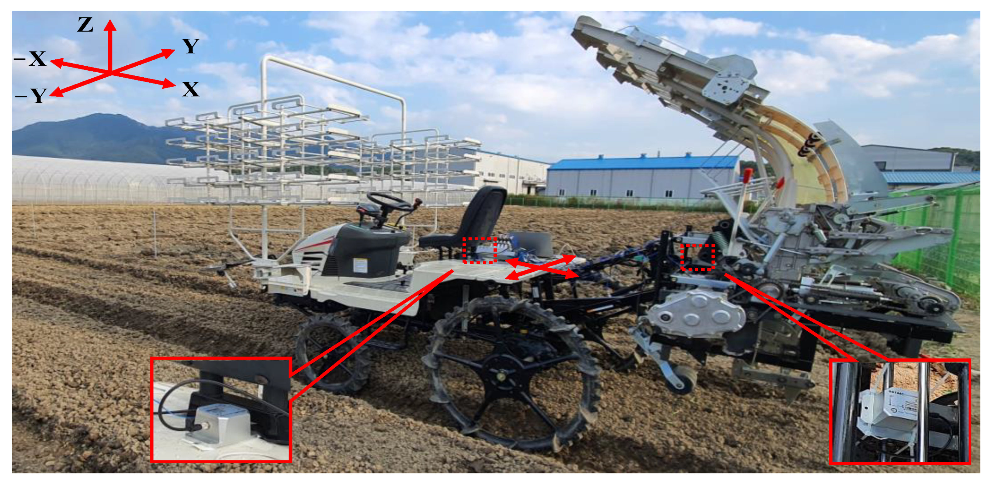
2.5.2. Analysis of Dynamic Stability Characteristics through Field Tests

The dynamic stability of the onion transplanter was evaluated through field tests using an inclinometer (SST300, Shanghai Vigor Technology Development Co., Ltd., Shanghai, China). The inclination meter measured the angle in the X- and Y-axis directions. One of the angle sensors was placed at the floor of the four-wheel vehicle to check the driving stability of the vehicle as well as the swing of the operator’s body. Another angle sensor was placed in the center of the transplanting section to assess the swing tendency during field operations or driving off-road. In this study, three types of driving surfaces, i.e., soil surface, unpaved road, and asphalt road with two driving speeds, such as low (0.12 m·s−1) and high (0.24 m·s−1), were considered. A total of six treatments with three replications were implemented. Figure 7 shows analysis of dynamic stability characteristics through field test.

2.6. Analytical Procedures

The statistical analysis of this study was performed using the Minitab 19.0 statistical package (ver. 2019, Minitab, Rd State College, PA, USA). Data obtained from the static stability validation tests were averaged, and the standard deviation (SD) was determined. For the dynamic stability analysis, raw data were pre-processed at first. The first and third quartiles, interquartile range, upper bound, and lower bound were calculated to remove noise and outliers. Some basic statistical analysis was performed using MS Excel (ver. 2018, Microsoft Corporation, Redmond, WA, USA).

3. Results

3.1. Evaluation of Gravity Coordinates

The mass of the 4-wheel vehicle, transplanter (vehicle + transplanting unit), transplanter with an operator, and transplanter with an operator and carrying load were 575, 1145, 1225, and 1265 kg, respectively. The mass holding ratios by the front- and rear-axles of the whole transplanter, the whole transplanter with an operator, and the whole transplanter with an operator and carrying load under the regular condition were 30.66%:69.34%, 34.045%:65.96%, and 35.49%:64.51%, and under the front axle lifted condition were 19.13%:80.87%, 21.96%:78.04%, and 23.72%:76.28%. Similarly, the mass ratios between the left- and right-sided wheels of the whole transplanter, the whole transplanter with an operator, and the whole transplanter with an operator and carrying load under the normal condition were 50.92%:49.08%, 51.18%:48.82%, and 51.15%:48.85%, and under the front axle lifted condition were 51.35%:48.65%, 51.43%:48.57%, and 51.46%:48.54%. According to Equations (1)–(3), the calculated CGV coordinates (XV, YV, and ZV) of the 4-wheel vehicle were 1016.34, −488.02, and 1188.86 mm, respectively. On the other hand, based on Equations (4)–(6), the CGT coordinates (XT, YT, and ZT) of the whole onion transplanter system for different load conditions and mass distributions are mentioned in Table 2.

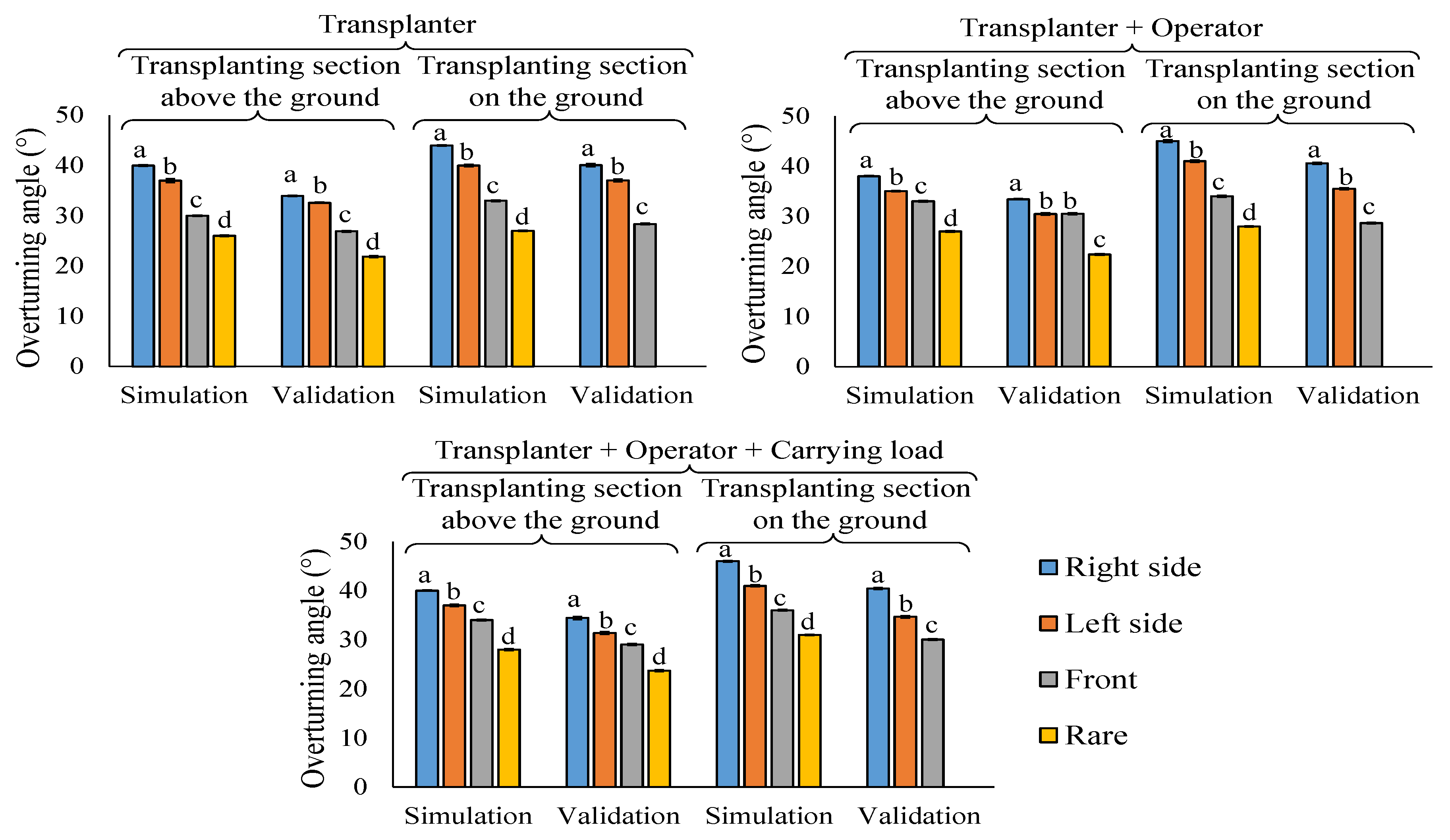
3.2. Characteristics of Static Stability

In this study, the static rollover angle was determined theoretically and evaluated through simulation and validated tests considering load conditions and the position of the attached transplanter. According to the physical properties of the onion transplanter, the critical rollover angle was theoretically 58.43°, and the transplanter will begin rolling over above this angle. The simulated lateral (right, left) and longitudinal (front, rear) rollover angles of the onion transplanter, the transplanter with an operator, and the transplanter with an operator and carrying load were 40°, 37°, and 30°, 26°; 38°, 35°, and 33°, 27°; and 40°, 37°, and 34°, 28°, respectively, when the transplanting section was above ground. Similarly, 44°, 40°, and 33°, 27°; 45°, 41°, and 34°, 28°; 46°, 41°, and 36°, 31° rollover angles were found when the transplanting section was on the ground (test bench). A similar rollover angle trend was observed after the validation tests. The angle difference between the simulation and validation was 3° to 6.5°. The symmetrical structure of the onion transplanter resulted in a 2° to 4° rollover angle difference between the right and left sides turning for all conditions tested. Similarly, a 5° to 8° difference in rollover angle was observed for the longitudinal (front and rear side) overturning. Figure 8 shows the lateral and longitudinal rollover angles based on the load conditions and position of the attached transplanter.

3.3. Characteristics of Dynamic Stability

While the transplanter started moving to power up the rear wheels, there was an angular velocity along the lateral axis of the transplanter. The effect of CG normalized this angular velocity, which helped the transplanter remain stable at the starting time. While the transplanter traveled on a sloped path, there was a change in the position of the CG. Theoretically, the transplanter remained stable on a 39° uphill track. Exceeding this angle (39°), the transplanter will become unstable and will be overturned.
The fluctuation of angles for different driving surfaces and speeds is shown in Figure 9. The average angle fluctuation of the vehicle and transplanting unit during driving on the soil surface was 4° and 6°, respectively, for both high and low driving speeds. However, the average fluctuating angle of the vehicle under the unpaved road condition was the same (4°), and a low fluctuation was observed (2°) for the transplanting unit. The separated X- and Y-axes indicate that the transplanting unit was mounted in a tilted condition while driving the onion transplanter. An almost similar situation was observed in the asphalt road condition. Although the obtained signal patterns differed slightly for each condition, there was no significant difference between the high and low driving speeds. The angle fluctuation pattern was primarily influenced by the driving surface condition for both the vehicle and transplanting unit.

4. Discussion

The rollover possibility of farm machinery mainly depends on its center of gravity. In this study, after attaching the transplanting unit with the 4-wheel vehicle, the gravity coordinates of the vehicle (XV, YV, and ZV) were moved by −92, 155, and −4 mm, respectively. The change in X and Y coordinates indicates a transfer of CG near the rear wheel axle of the vehicle due to the non-supporting self-mass of the transplanter, and the reduction in the Z coordinate reduces the overturning possibility partially as agricultural field machinery with a high positioned CG rolls over more frequently than agricultural field machinery with a lower-positioned CG [46,47]. A similar result was observed by [24]. After hitching the harvester to their experiment, the gravity coordinates changed from 957, −9, and 783 mm to 102, 402, and 770 mm. However, the coordinates of CG change in a different direction when the mass of the attached implement is supported independently [25].
According to ISO 16251-2 [33], the allowable range of the overturning angle is 15 to 45° based on different off-road farm machinery. In this study, stability angles varied from 23 to 45° in the unloaded condition and from 28 to 40° in the loaded condition for the different positions of the transplanting unit, which is very close to the ISO recommendation. Iqbal et al. [48] theoretically analyzed the rollover possibility of upland crop machinery (an automatic pepper transplanter), where they observed around 36° longitudinal and 40° lateral rollover angles during static conditions. The average difference between the simulated and validated left-sided overturning angles was 5°, which might be minimized by specifying the simulation coefficients more accurately. Some static stability validation tests could not be performed due to the severe damage possibility of the transplanter. According to the simulation results, the difference between the loaded and unloaded conditions was 2°, which might not affect the stability of the transplanter system. A similar pattern of findings was observed by Ayers [22] for different off-road vehicles under loaded and unloaded conditions. They observed 6 to 7° of angle variation for terrain vehicles, lawn tractors, off-road utility vehicles, and zero-turn radius mowers. Table 3 shows a brief survey of the static rollover angles of different farm machinery.
Growers prefer autonomous farm machinery with fast operating capability (high field capacity). However, operating farm machinery in any rough terrain in minimum time increases the possibility of rollover incidents. Speed and acceleration are the primary factors for the dynamic instability of off-road vehicles [51,52]. In this study, a negligible angle difference was observed due to speed and driving path variations. This might be because the tests were conducted in the machinery testing beds of TYM Tractors (TYM Tractors, Co., Ltd., Iksan, Republic of Korea), where the driving surfaces were homogenous in condition. Besides this, the operating speeds (0.12 and 0.24 m·s−1) of the transplanter were comparatively lower. For example, tractor-based tillage and cultivation operations (i.e., pesticide spray) were conducted at 0.5 to 2.0 m·s−1 speed [53]. This low operational speed might be another reason behind this low angle fluctuation.

5. Directions for Further Research

The test environments of this study were overly homogenous. Different terrains (i.e., slopes, hills) and on-site tests need to be considered to increase the validity and applicability of these results. Besides the inclination meter data, simulation and validation tests would be beneficial for analyzing dynamic rollover characteristics. In addition, advanced sensing technologies integrated with artificial intelligence, such as surface assessment and automatic driving using LiDAR sensors [54,55], unmanned or remote control using GPS and vision systems [56,57], the real-time feedback control of stability using inclinometers [58] could be included for operational accuracy, increasing machine efficiency, and predicting yield.

6. Conclusions

This study focused on the rollover characteristics of a 12 kW automatic onion transplanter to minimize stability hazards and ensure the operator’s safety. The CG coordinates and static stability angles were calculated mathematically, and static lateral and longitudinal rollover angles were simulated and validated considering different mounting positions of the transplanting unit and carrying load conditions. The dynamic rollover angle was calculated theoretically and evaluated based on the sensor data recorded while operating the onion transplanter on different surfaces and at different speeds. The theoretical and averaged simulated, validated rollover angles were 34.5°, 43.9°, and 31.4°, respectively. Due to the symmetrical structure, a 4.5° turning difference was observed between the right and left sides, and a 3° angle difference occurred due to the variation in load conditions. The calculated dynamic rollover angle was 39°, and a negligible angle difference was observed, 2~4° and 3~6° for the vehicle and transplanting unit, respectively, during driving on different surfaces and at driving speeds. Although the onion transplanter met the ISO standard, because it overturned at a greater than 31° angle, the lower position of the transplanting unit (on the ground) and the loaded condition is safer than other conditions. As most of the tests were conducted in the lab environment, the stability characteristics of the considered onion transplanter might vary slightly in field conditions. This study provides helpful information for ensuring the safety of upland crop machinery operating under rough and sloped field conditions.

Author Contributions

Conceptualization, S.-O.C. and M.C.; methodology, S.-O.C. and M.C.; software, M.C.; validation, M.C., M.A., E.H. and M.N.R.; formal analysis, M.C., M.A., E.H., M.N.R. and S.-O.C.; investigation, S.-O.C.; resources, S.-O.C.; data curation, M.C. and M.A.; writing—original draft preparation, M.C.; writing—review and editing, S.-O.C., M.S.N.K., S.-J.L. and I.-S.C.; visualization, M.C., M.S.N.K. and S.-O.C.; supervision, S.-O.C.; project administration, S.-O.C.; funding acquisition, S.-O.C. All authors have read and agreed to the published version of the manuscript.

Funding

This work was supported by the Korea Institute of Planning and Evaluation for Technology in Food, Agriculture and Forestry (IPET) through the Agriculture, Food and Rural Affairs Convergence Technologies Program for Educating Creative Global Leaders, funded by the Ministry of Agriculture, Food and Rural Affairs (MAFRA) (Project No. 320001-4), Republic of Korea.

Institutional Review Board Statement

Not applicable.

Informed Consent Statement

Not applicable.

Data Availability Statement

All the data reported here are available from the authors upon request.

Conflicts of Interest

The authors declare no conflict of interest.

Nomenclature

Variable notations, definitions, and measurement units
NotationsDefinitions and Units
F1, F2 Ground reaction forces acting on two different wheels, N
G Weight vector of the transplanter, N
GaWeight vector of the transplanter acting on the overturning point, N
wTrack width, mm
lWheelbase, mm
a, bDistance of CG from the left and right wheel, respectively, mm
αSlope angle, °
αcritCritical slope angle, °
TTransverse force acting on CG, N
NGround reaction force acting on CG, N
Gx, GzWeight vector components for X-, and Z-axis, respectively
xVertical direction of the resultant weigh vector, rad
ξStability coefficient, numeric
βAngle between the weight vector and the component towards the Z-axis in position (i), rad
XrVertical distance between the CG and rear-wheel overturning point, mm
ECGRotational radius of CG towards the overturning point, mm
δAngle between the (ii) and (iii) position of the CG, rad
γAngle between the X-axis and the connecting line of overturning point and CG of the transplanter in position (i), rad
KEKinetic energy induced for the rotation of the CG, J
PEPotential energy induced for the rotation of the CG, J
ωyAngular velocity of the transplanter related to Z-axis, rads−1
ωycritCritical angular velocity of the transplanter related to Z-axis, rads−1
JyInduced kinetic energy for the rotation of the CG, J
ωrAngular velocity for the rolling of the transplanter, rads−1
ωpAngular velocity for the pitching of the transplanter, rads−1
HHeight of the transplanter CG, mm
hcritCritical height of the CG of the transplanter, mm
hfFinal height of the CG of the transplanter while passing through any obstacle, mm
αrAngular acceleration for the rolling of the transplanter, rads−2
αpAngular acceleration for the pitching of the transplanter, rads−2
UExternal force on the transplanter during the dynamic condition, N
ΔTDifference in kinetic energy, J
ΔPDifference in potential energy, J
I xxMoment of inertia of the transplanter in X-axis, kg·mm−2
I yyMoment of inertia of the transplanter in Y-axis, kg·mm−2
mtMass of the transplanter, N
VcThe initial velocity of the transplanter while hits an obstacle in the path, mm·s−1
VfThe forward velocity of the transplanter, mm·s−1
θAngle between the overturning point and the peak of the obstacle, rad
ϕAngular displacement of the CG during passes through an obstacle, rad
ζDamping coefficient, numeric
ζn, ζtNormal and tangential damping coefficient, respectively, numeric
kSpring coefficient, numeric
kn, ktNormal and tangential spring coefficient, respectively, numeric
m1, m2, m3Stiffness, damping, and indentation exponent, respectively, numeric

References

  1. Lanzotti, V. The analysis of onion and garlic. J. Chromatogr. A 2006, 1112, 3–22. [Google Scholar] [CrossRef] [PubMed] [Green Version]
  2. Law, Y.-Y.; Chiu, H.-F.; Lee, H.-H.; Shen, Y.-C.; Venkatakrishnan, K.; Wang, C.-K. Consumption of onion juice modulates oxidative stress and attenuates the risk of bone disorders in middle-aged and post-menopausal healthy subjects. Food Func. 2016, 7, 902–912. [Google Scholar] [CrossRef] [PubMed]
  3. Sami, R.; Elhakem, A.; Alharbi, M.; Almatrafi, M.; Benajiba, N.; Ahmed Mohamed, T.; Fikry, M.; Helal, M. In-vitro evaluation of the antioxidant and anti-inflammatory activity of volatile compounds and minerals in five different onion varieties. Separations 2021, 8, 57. [Google Scholar] [CrossRef]
  4. Sharma, K.; Mahato, N.; Hariram Nile, S.; Tal Lee, E.; Rok Lee, Y. Economical and environmentally-friendly approaches for usage of onion (Allium cepa L.) waste. Food Func. 2016, 7, 3354–3369. [Google Scholar] [CrossRef] [PubMed]
  5. Zhao, X.-X.; Lin, F.-J.; Li, H.; Li, H.-B.; Wu, D.-T.; Geng, F.; Ma, W.; Wang, Y.; Miao, B.-H.; Gan, R.-Y. Recent advances in bioactive compounds, health functions, and safety concerns of onion (Allium cepa L.). Front. Nutr. 2021, 8, 669805. [Google Scholar] [CrossRef] [PubMed]
  6. Geisseler, D.; Ortiz, R.S.; Diaz, J. Nitrogen nutrition and fertilization of onions (Allium cepa L.)—A literature review. Sci. Hortic. 2022, 291, 110591. [Google Scholar] [CrossRef]
  7. Rasool, K.; Islam, M.; Ali, M.; Jang, B.-E.; Khan, N.; Chowdhury, M.; Chung, S.-O.; Kwon, H.-J. Onion transplanting mechanisms: A review. Prec. Agri. Sci. Technol. 2020, 2, 195–208. [Google Scholar] [CrossRef]
  8. Li, J.; Tang, Y.; Zou, X.; Lin, G.; Wang, H. Detection of fruit-bearing branches and localization of litchi clusters for vision-based harvesting robots. IEEE Access 2020, 8, 117746–117758. [Google Scholar] [CrossRef]
  9. Lin, G.; Zhu, L.; Li, J.; Zou, X.; Tang, Y. Collision-free path planning for a guava-harvesting robot based on recurrent deep reinforcement learning. Comput. Electron. Agric. 2021, 188, 106350. [Google Scholar] [CrossRef]
  10. Li, C.E.; Tang, Y.; Zou, X.; Zhang, P.; Lin, J.; Lian, G.; Pan, Y. A novel agricultural machinery intelligent design system based on integrating image processing and knowledge reasoning. Appl. Sci. 2022, 12, 7900. [Google Scholar] [CrossRef]
  11. Gao, Q.; Gao, F.; Tian, L.; Li, L.; Ding, N.; Xu, G.; Jiang, D. Design and development of a variable ground clearance, variable wheel track self-leveling hillside vehicle power chassis (V2-HVPC). J. Terramech. 2014, 56, 77–90. [Google Scholar] [CrossRef]
  12. Iqbal, M.Z.; Islam, M.N.; Chowdhury, M.; Islam, S.; Park, T.; Kim, Y.-J.; Chung, S.-O. Working speed analysis of the gear-driven dibbling mechanism of a 2.6 kW walking-type automatic pepper transplanter. Machines 2021, 9, 6. [Google Scholar] [CrossRef]
  13. Reza, M.N.; Islam, M.N.; Chowdhury, M.; Ali, M.; Islam, S.; Kiraga, S.; Lim, S.-J.; Choi, I.-S.; Chung, S.-O. Kinematic analysis of a gear-driven rotary planting mechanism for a six-row self-propelled onion transplanter. Machines 2021, 9, 183. [Google Scholar] [CrossRef]
  14. Ali, M.; Lee, Y.-S.; Chowdhury, M.; Khan, N.A.; Swe, K.M.; Rasool, K.; Kabir, M.S.N.; Lee, D.-H.; Chung, S.-O. Analysis of driving stability and vibration of a 20-kW self-propelled 1-row Chinese cabbage harvester. J. Biosyst. Eng. 2021, 46, 48–59. [Google Scholar] [CrossRef]
  15. Islam, M.N.; Iqbal, M.Z.; Ali, M.; Chowdhury, M.; Kabir, M.S.N.; Park, T.; Kim, Y.-J.; Chung, S.-O. Kinematic analysis of a clamp-type picking device for an automatic pepper transplanter. Agriculture 2020, 10, 627. [Google Scholar] [CrossRef]
  16. Chowdhury, M.; Gulandaz, M.A.; Kiraga, S.; Ali, M.; Reza, M.N.; Kwon, H.J.; Lee, D.H.; Chung, S.O. Turning stability analysis of a 12-kW self-propelled riding-type automatic onion transplanter to ensure user safety. IOP Conf. Ser. Earth Environ. Sci. 2021, 924, 012014. [Google Scholar] [CrossRef]
  17. Islam, M.N.; Iqbal, M.Z.; Ali, M.; Chowdhury, M.; Kiraga, S.; Kabir, M.S.N.; Lee, D.-H.; Woo, J.-K.; Chung, S.-O. Theoretical transmission analysis to optimise gearbox for a 2.6 kW automatic pepper transplanter. J. Agric. Eng. 2022, 53. [Google Scholar] [CrossRef]
  18. Islam, M.N.; Iqbal, M.Z.; Chowdhury, M.; Ali, M.; Shafik, K.; Kabir, M.S.N.; Lee, D.-H.; Chung, S.-O. Stress and fatigue analysis of picking device gears for a 2.6 kW automatic pepper transplanter. Appl. Sci. 2021, 11, 2241. [Google Scholar] [CrossRef]
  19. Rasool, K.; Ali, M.; Chowdhury, M.; Kwon, H.J.; Swe, K.M.; Chung, S.O. Theoretical analysis of velocity, acceleration and torque calculation of a five-bar onion transplanting mechanism. IOP Conf. Ser. Earth Environ. Sci. 2021, 733, 012019. [Google Scholar] [CrossRef]
  20. Chowdhury, M.; Islam, M.N.; Iqbal, M.Z.; Islam, S.; Lee, D.-H.; Kim, D.-G.; Jun, H.-J.; Chung, S.-O. Analysis of overturning and vibration during field operation of a tractor-mounted 4-row radish collector toward ensuring user safety. Machines 2020, 8, 77. [Google Scholar] [CrossRef]
  21. Qin, J.; Zhu, Z.; Mitsuoka, M.; Inoue, E.; Okayasu, T.; Hirai, Y.; Li, Z.; Song, Z. Coupled effect of slope angle and terrain roughness on tractor stability. J. Fac. Agric. 2018, 63, 355–360. [Google Scholar] [CrossRef]
  22. Ayers, P.; Conger, J.B.; Comer, R.; Troutt, P. Stability analysis of agricultural off-road vehicles. J. Agric. Saf. Health 2018, 24, 167–182. [Google Scholar] [CrossRef] [PubMed]
  23. Gillespie, T. Fundamentals of Vehicle Dynamics; Revised edition; SAE International: Warrendale, PA, USA, 2021; pp. 249–260. [Google Scholar]
  24. Choi, K.; Kim, S.-M.; Hong, S. Analysis of static stability by modified mathematical model for asymmetric tractor-harvester system: Changes in lateral overturning angle by movement of center of gravity coordinates. J. Biosyst. Eng. 2017, 42, 127–135. [Google Scholar] [CrossRef]
  25. Hong, S.; Lee, K.; Kang, D.; Park, W. Analysis of static lateral stability using mathematical simulations for 3-axis tractor-baler system. J. Biosyst. Eng. 2017, 42, 86–97. [Google Scholar] [CrossRef]
  26. Myers, M.L. Folding ROPS or automatically deployable ROPS? J. Agric. Saf. Health 2015, 21, 201–204. [Google Scholar]
  27. MAFRA. Agricultural Mechanization Promotion Act. Article 9. Available online: https://elaw.klri.re.kr/eng_mobile/viewer.do?hseq=50965&type=part&key=24 (accessed on 15 February 2023).
  28. Lozia, Z. Rollover thresholds of the biaxial truck during motion on an even road. Veh. Syst. Dyn. 1998, 29, 735–740. [Google Scholar] [CrossRef]
  29. Dukkipati, R.V.; Pang, J.; Qatu, M.S.; Sheng, G.; Shuguang, Z. Road Vehicle Dynamics; SAE international: Warrendale, PA, USA, 2008; pp. 311–353. [Google Scholar]
  30. Lozia, Z. Rollover of the biaxial vehicle (untripped case). Logistyka 2010, 4, 1–8. [Google Scholar]
  31. MAFF. Specific Farming Village Law-Direct Support System for Middle Mountainous Area. Available online: https://www.maff.go.jp/e/data/publish/ (accessed on 25 December 2022).
  32. Cao, D.; Song, X.; Ahmadian, M. Editors’ perspectives: Road vehicle suspension design, dynamics, and control. Veh. Syst. Dyn. 2011, 49, 3–28. [Google Scholar] [CrossRef] [Green Version]
  33. ISO 789-6; 1982 Agricultural Tractors—Test Procedures—Part 6: Centre of Gravity. International Organization for Standardization, ISO: Geneva, Switzerland, 1982.
  34. ISO 16231-2; 2015 Self-Propelled Agricultural Machinery—Assessment of Stability—Part 2: Determination of Static Stability and Test Procedures. International Organization for Standardization, ISO: Geneva, Switzerland, 2015.
  35. Khorsandi, F.; Ayers, P.D.; Freeland, R.S.; Wang, X. Modeling the effect of liquid movement on the center of gravity calculation of agricultural vehicles. J. Terramech. 2018, 75, 37–48. [Google Scholar] [CrossRef]
  36. Wang, X.; Gao, L.; Ayers, P.D.; Su, S.; Yuan, C. The influence of the lift angle on the center of gravity: Measurements for zero turning radius mowers. Appl. Eng. Agric. 2016, 32, 189–199. [Google Scholar]
  37. ANSI/OPEI B71.9; 2016—Multipurpose Off-Highway Utility Vehicles. American National Standards Institute (ANSI): New York, NY, USA, 2016.
  38. ANSI/OPEI B71.4; 2017 Commercial Turf Care Equipment Safety Specifications: Changes. American National Standards Institute (ANSI): New York, NY, USA, 2017.
  39. ANSI/ASABE AD26322-1; 2008 Tractors for Agriculture and Forestry—Safety—Part 1: Standard Tractors. American National Standards Institute (ANSI): New York, NY, USA, 2008.
  40. ANSI/ASABE AD26322-2; 2010 Tractors for Agriculture and Forestry—Safety—Part 2: Narrow-Track and Small Tractors. American National Standards Institute (ANSI): New York, NY, USA, 2010.
  41. ASAE/ASABE S318.18; 2017 Safety for Agricultural Field Equipment. The American Society of Agricultural and Biological Engineers (ASABE): New York, NY, USA, 2017.
  42. ANSI/SVIA 1; 2017 American National Standard for Four Wheel All-Terrain Vehicles. American National Standards Institute (ANSI): New York, NY, USA, 2017.
  43. Dabbour, E.; Dabbour, O.; Martinez, A.A. Temporal stability of the factors related to the severity of drivers’ injuries in rear-end collisions. Accid. Anal. Prev. 2020, 142, 105562. [Google Scholar] [CrossRef] [PubMed]
  44. Phanomchoeng, G.; Rajamani, R. New rollover index for the detection of tripped and untripped rollovers. IEEE Trans. Ind. Electron. 2013, 60, 4726–4736. [Google Scholar] [CrossRef]
  45. Rédl, J.; Váliková, V.; Antl, J. Design of active stability control system of agricultural off-road vehicles. Res. Agric. Eng. 2014, 60, S77–S84. [Google Scholar] [CrossRef] [Green Version]
  46. Fargnoli, M.; Lombardi, M. Safety vision of agricultural tractors: An engineering perspective based on recent studies (2009–2019). Safety 2020, 6, 1. [Google Scholar] [CrossRef] [Green Version]
  47. Reński, A. Investigation of the Influence of the Centre of Gravity Position on the Course of Vehicle Rollover. In Proceedings of the 24th International Technical Conference on the Enhanced Safety of Vehicles (ESV) National Highway Traffic Safety Administration, Gothenburg, Sweden, 8–11 June 2015; pp. 8–11. [Google Scholar]
  48. Iqbal, M.Z.; Islam, M.N.; Ali, M.; Kiraga, S.; Kim, Y.-J.; Chung, S.-O. Theoretical overturning analysis of a 2.6-kW two-row walking-type automatic pepper transplanter. J. Biosyst. Eng. 2022, 47, 79–91. [Google Scholar] [CrossRef]
  49. Jang, B.E.; Chowdhury, M.; Ali, M.; Islam, M.N.; Swe, K.M.; Jung, D.U.; Lee, S.H.; Chung, S.O. Stability and vibration analysis of a tractor-mounted Chinese cabbage collector. IOP Conf. Ser. Earth Environ. Sci. 2021, 733, 012021. [Google Scholar] [CrossRef]
  50. Lysych, M.N. A study of the static lateral stability of a tillage machine-tractor unit on a virtual stand. J. Phys. Conf. Ser. 2020, 1515, 042033. [Google Scholar] [CrossRef]
  51. Mann, M.; Shiller, Z. Dynamic stability of off-road vehicles: Quasi-3D analysis. In Proceedings of the 2008 IEEE International Conference on Robotics and Automation, Pasadena, CA, USA, 19–23 May 2008; pp. 2301–2306. [Google Scholar]
  52. Bietresato, M.; Mazzetto, F. Definition of the layout for a new facility to test the static and dynamic stability of agricultural vehicles operating on sloping grounds. Appl. Sci. 2019, 9, 4135. [Google Scholar] [CrossRef] [Green Version]
  53. Noboru, N.; Michio, K.; Kazunobu, I.; Hideo, T. Field automation using robot tractor. In Proceedings of the Automation Technology for Off-Road Equipment Proceedings of the 2002 Conference, Chicago, IL, USA, 26–27 July 2002; American Society of Agricultural and Biological Engineers: St. Joseph, MI, USA; pp. 239–245. [Google Scholar]
  54. Shan, Y.; Yao, X.; Lin, H.; Zou, X.; Huang, K. LiDAR-based stable navigable region detection for unmanned surface vehicles. IEEE Trans. Instrum. Meas. 2021, 70, 8501613. [Google Scholar] [CrossRef]
  55. Li, Y.; Ibanez-Guzman, J. Lidar for autonomous driving: The principles, challenges, and trends for automotive lidar and perception systems. IEEE Signal Process. Mag. 2020, 37, 50–61. [Google Scholar] [CrossRef]
  56. Kanagasingham, S.; Ekpanyapong, M.; Chaihan, R. Integrating machine vision-based row guidance with GPS and compass-based routing to achieve autonomous navigation for a rice field weeding robot. Precis. Agric. 2020, 21, 831–855. [Google Scholar] [CrossRef]
  57. Wang, T.; Chen, B.; Zhang, Z.; Li, H.; Zhang, M. Applications of machine vision in agricultural robot navigation: A review. Comput. Electron. Agric. 2022, 198, 107085. [Google Scholar] [CrossRef]
  58. Pei, H.; Zhang, S.; Borana, L.; Zhao, Y.; Yin, J. Slope stability analysis based on real-time displacement measurements. Measurement 2019, 131, 686–693. [Google Scholar] [CrossRef]
Figure 1. A 3-D model of the considered automatic onion transplanter: (a) front view, (b) side view, (c) onion seedlings used for transplantation, and (d) a dimensional representation of the transplanting pattern.
Agriculture 13 00652 g001
Figure 2. Schematic diagram of the transference of CG of the onion transplanter: (a) side view, and (b) top view.
Agriculture 13 00652 g002
Figure 3. Schematic view of the lateral rollover of the onion transplanter: (a) normal condition, (b) stable condition, (c) critical (trending to rollover) condition.
Agriculture 13 00652 g003
Figure 4. Simulation of the static rollover of the onion transplanter: (a) normal condition of the onion transplanter on the tilt bench, (b) simulated lateral stability test, and (c) simulated longitudinal stability test.
Agriculture 13 00652 g004
Figure 5. Validation of the static stability: (a) normal condition of the onion transplanter on the tilt bench, (b) validation of lateral stability, and (c) validation of longitudinal stability.
Agriculture 13 00652 g005
Figure 6. Schematic view of the dynamic rollover of the onion transplanter during operation on an uphill path: (a) continuous operation in an upward direction, where positions (i) to (iii) indicate the displacement of the CG, and (b) facing an obstacle in the driving path.
Agriculture 13 00652 g006
Figure 7. Dynamic stability evaluation of the onion transplanter on soil surface.
Agriculture 13 00652 g007
Figure 8. Simulation and validation of the lateral and longitudinal rollover angles of the onion transplanter system under different load conditions and the mounted status of the transplanting unit. Here, a, b, c, d: different letters indicate significant differences (p ≤ 0.05).
Agriculture 13 00652 g008
Figure 9. Assessment of dynamic stability of the onion transplanter under: (a) soil surface, (b) unpaved road, and (c) asphalt road conditions considering high and low driving speeds.
Agriculture 13 00652 g009
Table 1. Specifications of the 12 kW self-propelled riding-type automatic onion transplanter.
Physical PropertiesMass Distribution
Specification of 4-wheel vehicleMass of driver (kg)80
Length (mm)2602Mass of carrying load (kg)40
Width (mm)17164-wheel vehicle
Height (mm)1648Mass in front left wheel, WVFl (kg)250
Front wheel track, W2 (mm)1400Mass in front right wheel, WVFr (kg)237
Rear wheel track, W1 (mm)1400Mass in rear left wheel, WVRl (kg)32
Front wheel radius, r2 (mm)650Mass in rear right wheel, WVRr (kg)56
Rear wheel radius, r1 (mm)950Total mass, WV (kg)575
Wheelbase, L1 (mm)1200Whole transplanterNormalLifted
Rear axle to three-point hitch, L2 (mm)1200Mass in front left wheel, WTFl (kg)198124
Transmission levelHSTMass in front right wheel, WTFr (kg)15395
Maximum power (kW·rpm−1)16.2/3400Mass in rear left wheel, WTRl (kg)385464
Front tread width (mm)80Mass in rear right wheel, WTRr (kg)409462
Rear tread width (mm)150Total mass, WT (kg)1145
Front and rear tire radius diff. (mm)70Whole Transplanter + Operator
Specification of the whole transplanterMass in front left wheel, WTFl (kg)230149
Length (mm)875Mass in front right wheel, WTFr (kg)187120
Width (mm)1626Mass in rear left wheel, WTRl (kg)397481
Height (mm)2036Mass in rear right wheel, WTRr (kg)411475
Ground clearance (mm)850Total mass, WT (kg)1225
Number of rows6Whole transplanter + Operator + Carrying load
Row spacing (mm)200Mass in front left wheel, WTFl (kg)246164
Hill spacing (mm)174Mass in front right wheel, WTFr (kg)203136
Power take-off (rpm)74Mass in rear left wheel, WTRl (kg)401487
Transplanting speed (m·s−1)0.24Mass in rear right wheel, WTRr (kg)415478
Transplanting mechanismMechanicalTotal mass, WT (kg)1265
Table 2. Summary of the CGS coordinates (XT, YT, and ZT) of the whole onion transplanter system for different load conditions and mass distributions.
CGS
Coordinates
TransplanterTransplanter
+ Operator
Transplanter + Operator +
Carrying Load
NormalLiftedNormalLiftedNormalLifted
XT (mm)367.86229.52408.49263.51425.93284.58
YT (mm)−307.69−338.47−352.55−382.71−380.54−409.01
ZT (mm)429.86454.99609.77493.94628.47516.04
Table 3. A summary of the static rollover angle for different farm machinery.
Static Rollover Angle of Different
Farm Machinery
Lateral RolloverReference
LeftRight
Tractor-baler system19.5°19.5°[25]
Cabbage harvester32°30°[14]
Radish collector26.74°38.07°[20]
Chinese cabbage collector33.2°45.6°[49]
Pepper transplanter40.67°40.67°[48]
Tractor with tillage implement36°36°[50]
Terrain vehicles41.3°33.7°[22]
Off-road utility vehicles 46.2°37.7°[22]
Lawn tractors 40°36.4°[22]
Disclaimer/Publisher’s Note: The statements, opinions and data contained in all publications are solely those of the individual author(s) and contributor(s) and not of MDPI and/or the editor(s). MDPI and/or the editor(s) disclaim responsibility for any injury to people or property resulting from any ideas, methods, instructions or products referred to in the content.

