Article

Design and Experimental Study of the Key Components of a Rape (Brassica campestris) Shoots (Changxiangtai 603) Flexible Clamping Harvester

1
College of Mechanical and Electrical Engineering, Hunan Agriculture University, Changsha 410128, China
2
Modern Agricultural College, Yiyang Vocational & Technical College, Yiyang 413049, China
3
Collaborative Innovation Center of Southern Chinese Grain and Oilseed, Changsha 410128, China
*
Author to whom correspondence should be addressed.
Agriculture 2023, 13(4), 792; https://doi.org/10.3390/agriculture13040792
Submission received: 2 March 2023 / Revised: 27 March 2023 / Accepted: 28 March 2023 / Published: 30 March 2023
(This article belongs to the Section Agricultural Technology)

Abstract

:
In view of the current situation of the low degree of mechanized harvesting of rape shoots, combined with the study of the material characteristics of rape shoots, the core components of the harvester were designed and analyzed, and a rape shoots harvester was designed and manufactured. The front-end cutter of the harvester cuts the stalks of rape shoots, while the clamping and conveying device transports and steers the stalks flexibly to achieve low damage and orderly harvesting. The forward speed of the machine, the speed of the clamping belt and the clamping gap were selected as the test factors, while the rate of missed cut, missed clamping, and plant damage were selected as the evaluation indexes for the single-factor and response surface optimization tests. Field validation test showed that the machine could effectively cut and transport rape shoots at a forward speed, clamping belt speed and clamping gap of 0.42 m/s, 0.89 m/s and 11.43 mm, respectively (missed cut rate, 2.63%; missed clamp rate, 4.84%; and plant damage rate, 5.22%). This study provides a reference for the research and optimization of the flexible harvesting device for rape shoots.

1. Introduction

1.1. Research Purpose and Current Situation

Rape is the third largest oilseed crop worldwide, with the largest planting area in China. Rape is widely distributed in the middle and lower reaches of the Yangtze River [1,2]. Rape (rape shoot) has in recent years been used as vegetable due to the development and promotion of double-low kale-type rape. Moreover, rape shoots, as vegetables, have excellent taste, flavor and high nutritional value [3,4]. The traditional manual harvesting method for rape shoots is labor-intensive and inefficient, thus significantly limiting the industrialization of rape shoots [5,6,7].
Only the shoots of rape (stem and leaf) are used as vegetables. The existing harvesting machinery for stem and leafy vegetable parts can be divided into two according to the degree of orderly piling after harvesting (disorderly harvesting and orderly harvesting). Compared with disorderly harvesting, orderly harvesting of vegetables with good piling quality saves time since it avoids secondary cleaning after harvesting. Experts and scholars have carried out a lot of research on orderly harvesting machinery. Hachiya et al. [8] developed a traction-type kale harvester, where the cutter cuts the kale, then transports it to the manual work platform at the back end through the clamping and conveying device at the front end. The processing, boxing and palletizing of kale is then completed on the manual work platform. However, multiple people are required to work at the same time. HORTECH (Italy) developed a SLIDE-CRAB-type leafy vegetable orderly harvester [9] with a double corrugated clamping conveyor belt that can flexibly clamp vegetable roots and stems to avoid vegetable damage during the conveying process, providing a reference for the development of subsequent flexible clamping models. Didamony et al. [10] developed a prototype harvester for the mechanized harvesting of Egyptian cabbage. The harvester was equipped with a cutter inclination adjustment device to adjust the cutting inclination during the working process, and the experiment proved that the harvesting efficiency and mechanized operation level of Egyptian cabbage can be improved. Liu et al. [11] designed an orderly harvester for low-loss harvesting of Chinese little greens by combining high-efficiency and low-loss cutting technology with flexible feeding technology. They also determined the degree of influence of each working parameter on machine efficiency through experiments, and results showed that this model could complete the mechanized harvesting of Chinese little greens. Shi et al. [12] established a model of each component and virtual assembly using Pro/E to design a virtual prototype of an orderly harvester for stem and leaf vegetables. They optimized the structural parameters of the device through virtual simulation tests to ensure the design accuracy and harvesting efficiency of the whole machine. Zhang et al. [13] designed a crawler self-propelled single-row cabbage harvester that could simultaneously complete the harvesting operations of cutting roots, clamping and guiding, conveying and boxing of cabbage. This model was stable and met the basic requirements of mechanized cabbage harvesting.
Mechanized harvesting technology, such as kale harvesters, cabbage harvesters and lettuce harvesters, is relatively mature in developed countries [14,15,16]. The mechanized harvesters have commercially promoted models. However, the foreign models do not have good applicability in China due to differences in operating environment, operating objects and consumer habits. Many key breakthroughs have been made in domestic mechanization research on small leafy vegetables in recent years. Moreover, most small leafy vegetable harvesting machines in commercial circulation have been localized. However, there are very few studies on mechanized harvesting of spherical vegetables and Brassica napus vegetables, with few mature models for commercial promotion, highly dependent on imports, which increases production costs. Therefore, localization is important to reduce the purchase cost of machines [17,18].
Since rape shoots are used as a vegetable after harvest, it is necessary to ensure the efficiency of the harvest and the quality of the sales of the rape shoots after harvest; so, the rape shoots harvester needs to achieve flexible harvesting. In this paper, a rape shoot harvester was designed considering the characteristics of rape shoots for cutting, clamping and conveying, and collecting rape shoots in the field. The key components of the harvester, such as a cutting device and a flexible clamping and conveying device, were also analyzed and field tests were conducted to ensure that the harvester could harvest the rape shoots with low damage and high efficiency. This study provides a reference for the research and optimization of flexible harvesting devices for rape shoots.

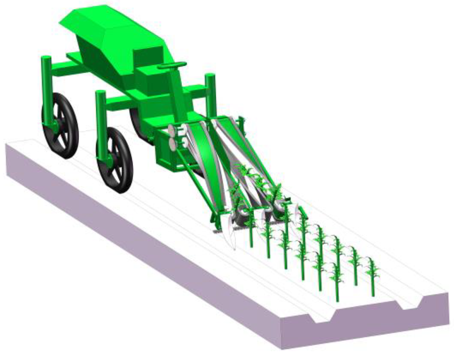
1.2. General Structure of Rape Shoots Harvester

The rape shoot harvester is mainly composed of a cutting device, crop divider, suppression wheel, flexible clamping conveyor belt, synchronous transmission gear, discharge port, clamping belt power input shaft, frame, separation partition, belt tensioning and clamping spacing adjustment device and feeding port. The structure is shown in Figure 1.

1.3. Working Principle and Technical Parameters

The harvester is suspended from the front of the self-propelled chassis in the upland gap, and the power provided by the chassis drives the cutting knife and the flexible clamping conveyor belt to simultaneously operate. Its working diagram is shown in Figure 2; the rape shoots converge on the front of the feeding port under the action of the crop divider as the machine moves. During this process, the lower stalk of rape shoots is in contact with the cutter, while the upper end is in contact with the flexible clamping conveyor belt. The cutter cuts off the lower stalk of rape shoots as the flexible clamping conveyor belt rolls the cut rape shoots into the flexible clamping conveyor device. The rape shoots are then deflected from the vertical direction 90° to the horizontal direction under the action of the belt, then passed through the discharge port to the collection area, completing the whole rape shoot harvesting work.
The main technical parameters of the rape shoot harvesting machine are shown in Table 1.

2. Materials and Methods

2.1. Planting Parameters of Rape Shoots

According to the principle of agricultural machinery and agronomic integration, it is necessary to clarify the planting parameters of crops before determining some agricultural machinery parameters. In this paper, the rape shoot variety “Changxiangtai603”, which was mechanically seeded by the 2BYL-4-type rape ridge fertilization combined seeder independently developed by Hunan Agricultural University, was studied. The seeds were sown in Anxiang County, Changde City, on 20 September 2021. Its planting parameters are shown in Table 2.

2.2. Material Characteristics of Rape Shoots

2.2.1. Basic Physical Parameters of Rape Shoots

In this paper, the material characterization of rape shoots was conducted by sampling on 18 November 2021. The sampling process was performed according to GB/T 5262-2008 “General Provisions on Test Conditions and Methods of Determination”, and the field test sampling was conducted via the “Five-point method” [19]. Analysis of each parameter was repeated ten times, and the average value was taken. The basic physical parameters of rape shoots are shown in Table 3.

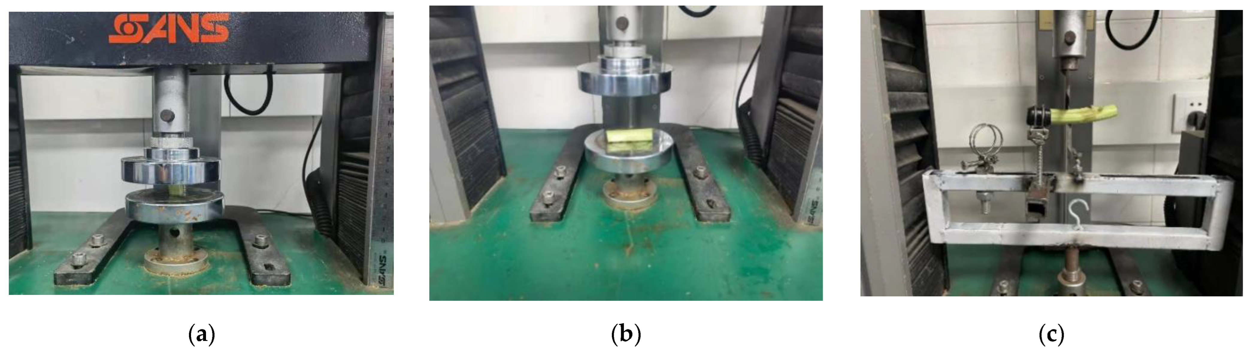
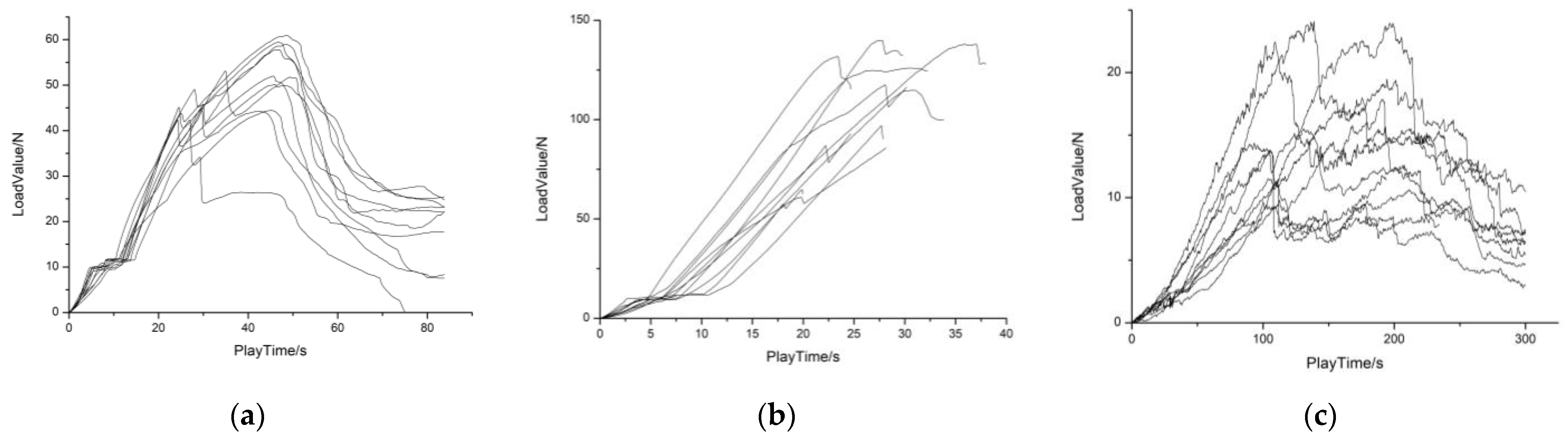
2.2.2. Mechanical Properties of Rape Shoot Stalks

For mechanized orderly harvesting, the rape shoots needed to be cut, clamped and transported. The mechanical forces mainly act on the cut and clamped sections of the stalk. In the case of harvester operation, this is to ensure that the rape shoot stalk can be cut off smoothly in the shearing process and not be crushed in the clamping conveying process. Reference [20] measured parameters such as modulus of elasticity and shear modulus of rape shoots plants. The mechanical properties of the cut and clamped sections of the stalk were analyzed using a microcomputer-controlled electronic universal testing machine (SANS-CMT6104). The mechanical properties of rape shoot stalks were tested as shown in Figure 3.
The calculation formula of the respective parameter was as in [20]:
E = σ ε 1 = Fl 0 S Δ l G = E 2 ( 1 + μ ) μ = ε 2 ε 1 = Δ Dl 0 Δ lD 0
where E is Young’s modulus of rape shoots stalk, MPa; G denotes shear modulus of rape shoots stalk, MPa; μ is Poisson’s ratio; σ is stress on rape shoots stalk, MPa; F is pressure on rape shoots stalk during the test, N; S represents cross-sectional area of rape shoots stalk before the test, mm2; l0 denotes length of rape shoots stalk before the test, mm; D0 is diameter of rape shoots stalk before the test, mm; ∆l expresses change in length of rape shoots stalk before and after the test, mm; ∆D is change in diameter of rape shoots stalk before and after the test, mm; ε1 expresses longitudinal strain; ε2 is transverse strain.
The mechanical properties curve of the rape shoot stalks are shown in Figure 4. The axial modulus of elasticity, shear modulus and Poisson’s ratio of rape shoots were 2.17 MPa, 0.76 Mpa and 0.43, respectively. The radial modulus of elasticity, shear modulus and Poisson’s ratio were 20.31 Mpa, 7.31 Mpa and 0.39, respectively.

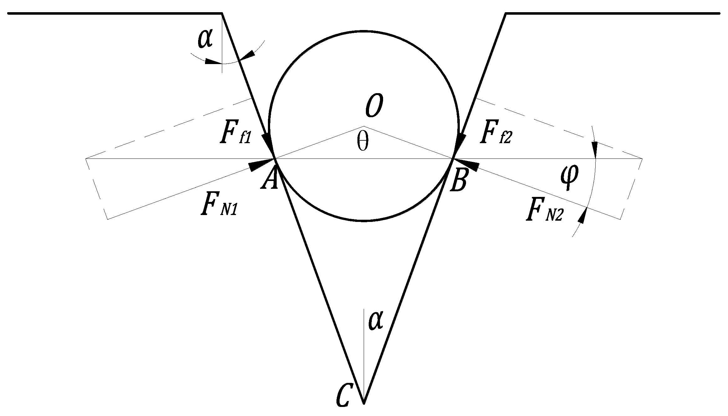
2.3. Cutting Mechanism of Cutting Device

2.3.1. Cutting Device Clamped Stalk Conditions

In this paper, a trapezoidal blade was selected for cutting rape shoots. A large blade slide cutting angle, α, may damage the stalk in the cutting process because it is not clamped by the cutting knife and affect the efficiency of the cutting device. Therefore, the size of the slide cutting angle should be determined only when the stalk is clamped by the cutting knife. Schematic of the stalk clamped by the cutting knife is shown in Figure 5 (the stalk is in the critical state of detachment and clamped) [21].
The clamped stalk is subjected to the joint action of the friction force Ff1 and the positive pressure FN1 of the left-end cutter, and the friction force Ff2 and the positive pressure FN2 of the right-end cutter. In Figure 5, α and φ represent the sliding angle of the cutter and friction angle of the cutter on the stalk of rape shoots, respectively. The force exerted by the left-end cutter on the stalk and the right-end cutter should cancel each other to ensure that the combined force on the stalk is zero (the combined force of the left blade and the right blade should be in the same line). The two blades form ΔOAB since they are identical:
θ + 2 φ = π
Additionally, the right angles ∠OAC and ∠OBC form OABC:
θ + 2 α = π
α should be less than φ for the stalk to be clamped. In this study, the friction angle of the cutter on the stalk of green leafy vegetables was 25–32° [22], and the sliding angle of the cutter blade was 20° (based on previous studies) to ensure that the stalks of rape shoots were clamped during the cutting process.

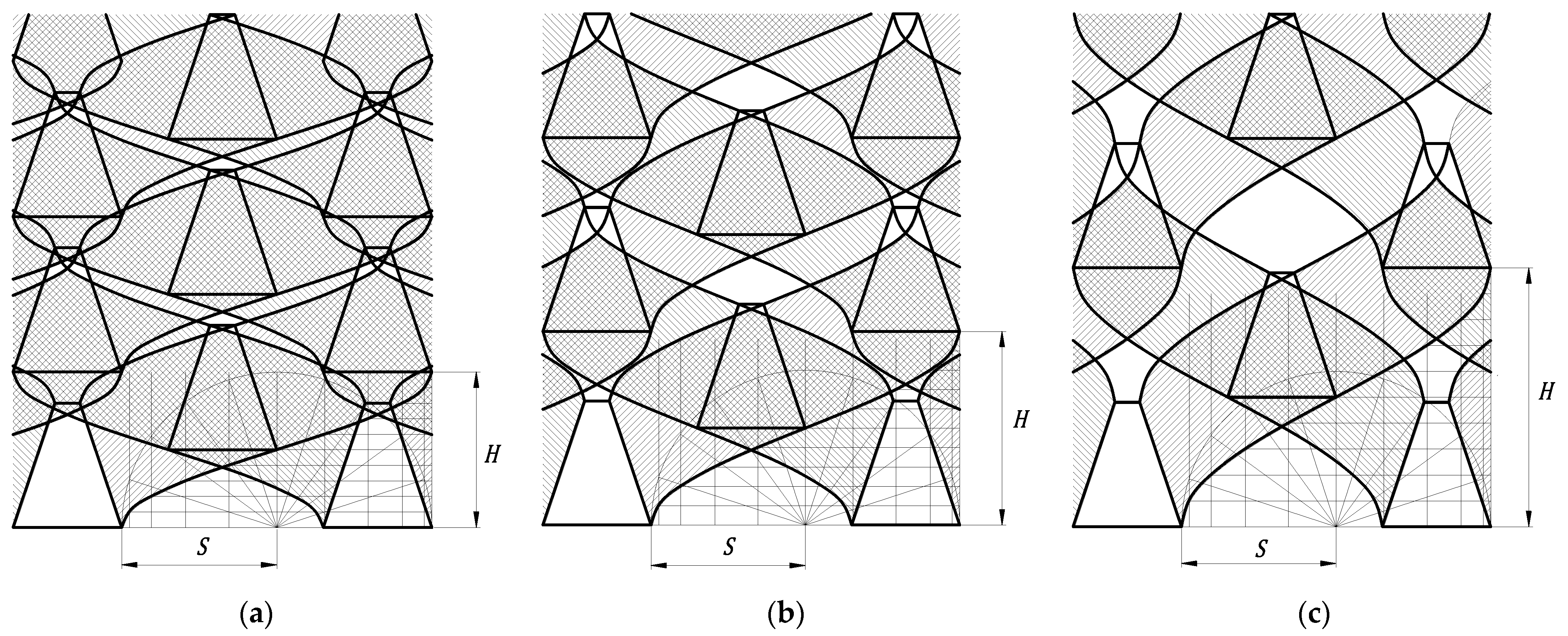
2.3.2. Cutting Speed Ratio

The motion of the cutter of the reciprocating cutter was synthesized by the reciprocating motion of the cutter and the forward motion of the machine. The instantaneous speed of the cutter changes at all times since the cutter is driven by the eccentric wheel for reciprocating motion. Herein, the average speed vp of the cutter was used as the cutter speed to simplify the analysis.
v p = nS 30 = nr 15
The cutter feed distance H is usually used to express the relationship between the cutter speed vp and the machine forward speed vm. The cutter feed distance is defined as the distance that the machine moves within one reciprocal stroke of the cutter movement, and it is calculated by the following formula:
H = v m t = 30 v m n
where n, t and S represent the crank speed (r/min), time for one stroke of the cutter movement (s) and cutter stroke (m), respectively.
The cutting rate ratio λ is defined as the ratio of the cutter speed to the forward speed of the machine, and it significantly affects the cutting quality of the cutter. Therefore, the best cutting rate ratio of the cutter should be identified to optimize the efficiency of the cutting device. The cutting rate ratio is calculated as shown below:
λ = v p v m = nS 30 nH 30 = S H
The range of values of the cutting rate ratio in the field of agricultural engineering is usually determined using the cutting graph method [23], after which an absolute trajectory of the cutter movement under different cutting rate ratios can then be drawn via CAD drawing software to analyze the cutting process of the device.
In Figure 6, I, II and III represent blank area, primary cutting area and repeated cutting area, respectively. The cutting knife feed distance, H, significantly influences the distribution of each area. An increase in the feed distance increases the blank area, decreases the re-cutting area and decreases the feed distance. Therefore, the cutting knife feed distance should be reduced appropriately since the stalks of rape shoots are easily bent, and the market demands high-quality rape shoots. Notably, repeat cutting can lead to power loss.
In this paper, the cutting speed ratio of the cutting device was 0.8. A cutting speed ratio of 0.6 may lead to low quality of the harvested rape shoots since the blank area will be about 20%. This harvesting machine is an upland system self-propelled front-hanging type. Therefore, the machine’s forward speed should not be too fast (1~3 km/h) to prevent rollover. The cutting speed of the cutter can be determined according to the cutting speed ratio.

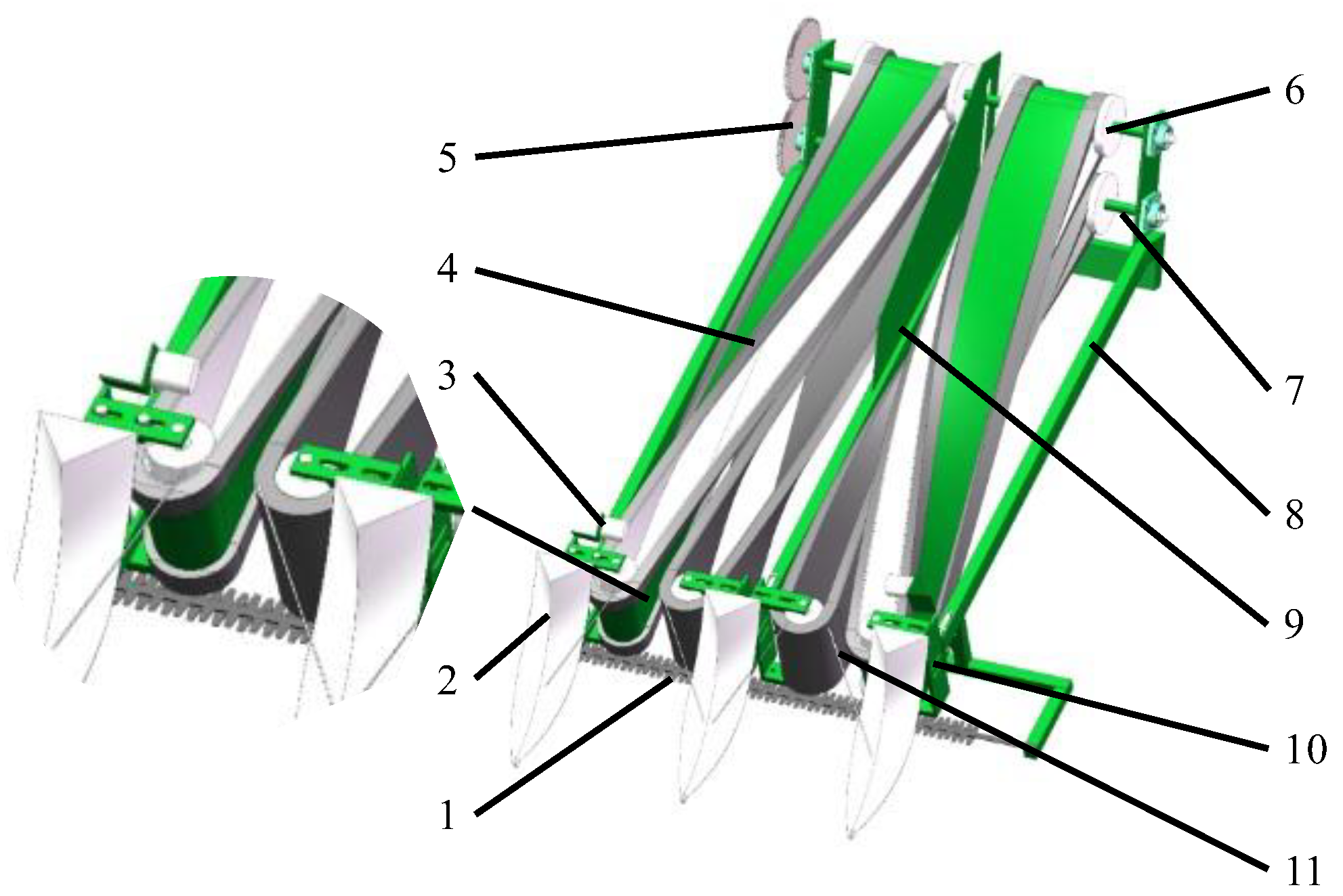
2.4. Design and Analysis of Clamping and Conveying Device

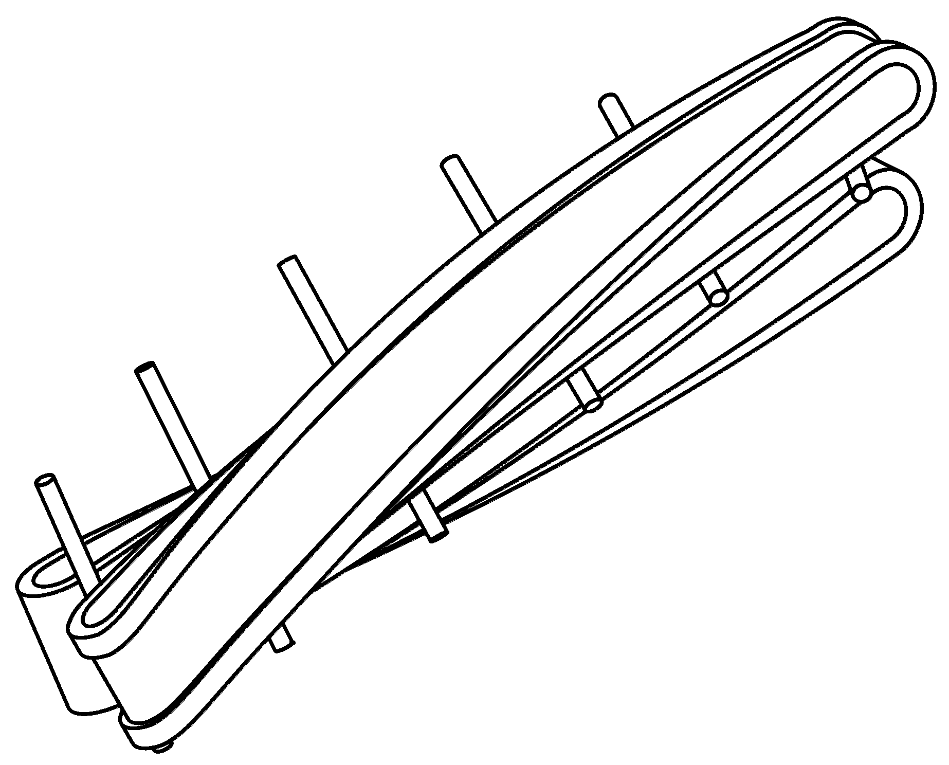
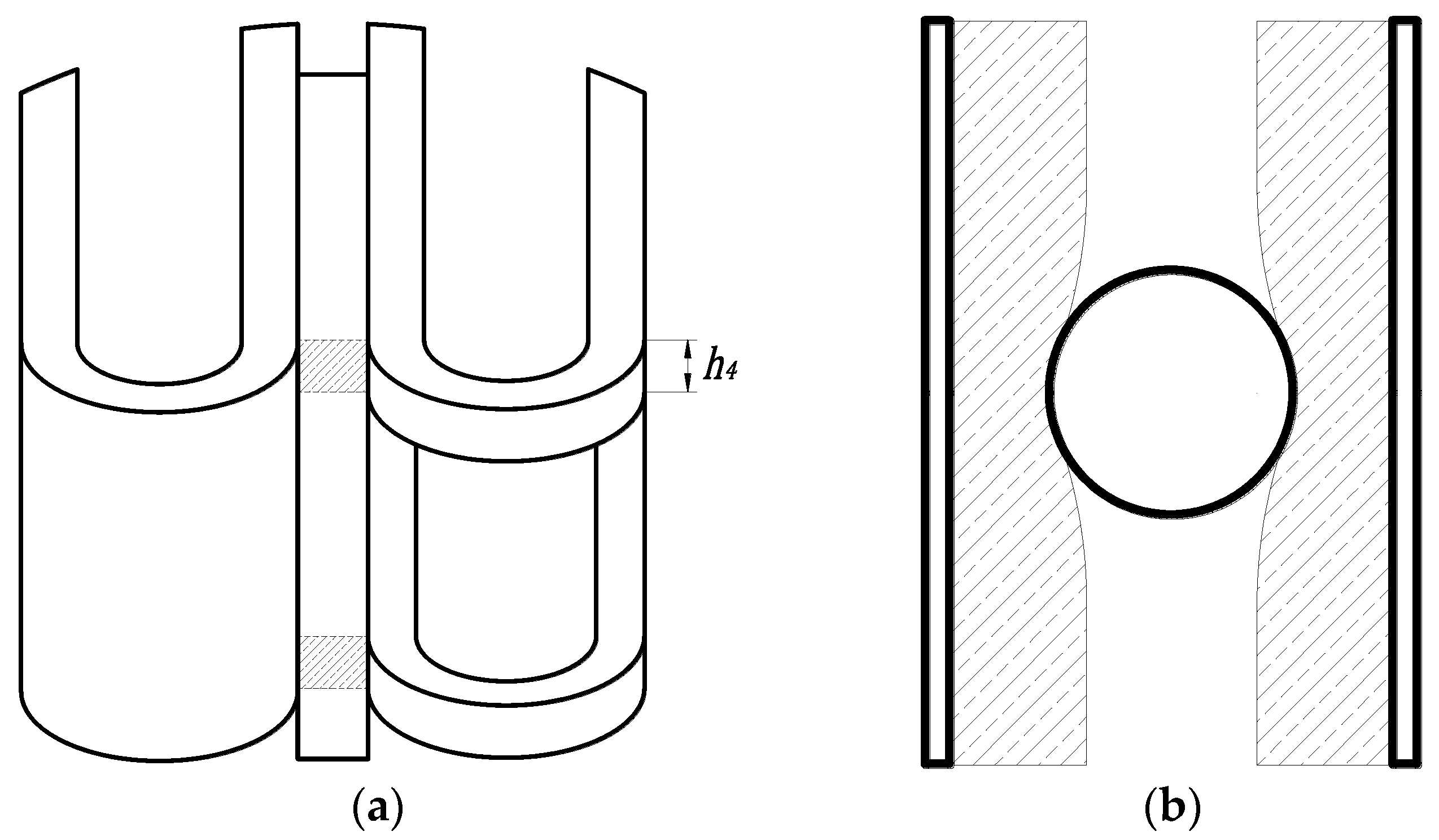
2.4.1. Design of Flexible Clamping and Conveying Device

The clamping and conveying device is the core component of the rape shoot harvester. The device clamps and conveys the cut rape shoots after the front cutting device is completed and the subsequent packing operation is performed. The device achieves orderly spreading through twisted belt clamping and conveying, ensuring 90° deflection of rape shoots from vertical direction to horizontal direction. The specific working state of the device is shown in Figure 7.
The belt tensioning and clamping distance adjustment device is attached to the port to adjust the working condition of the clamping conveyor. The conveyor belt is equipped with a flexible sponge for flexible clamping and conveying effect to reduce damage to rape shoots.

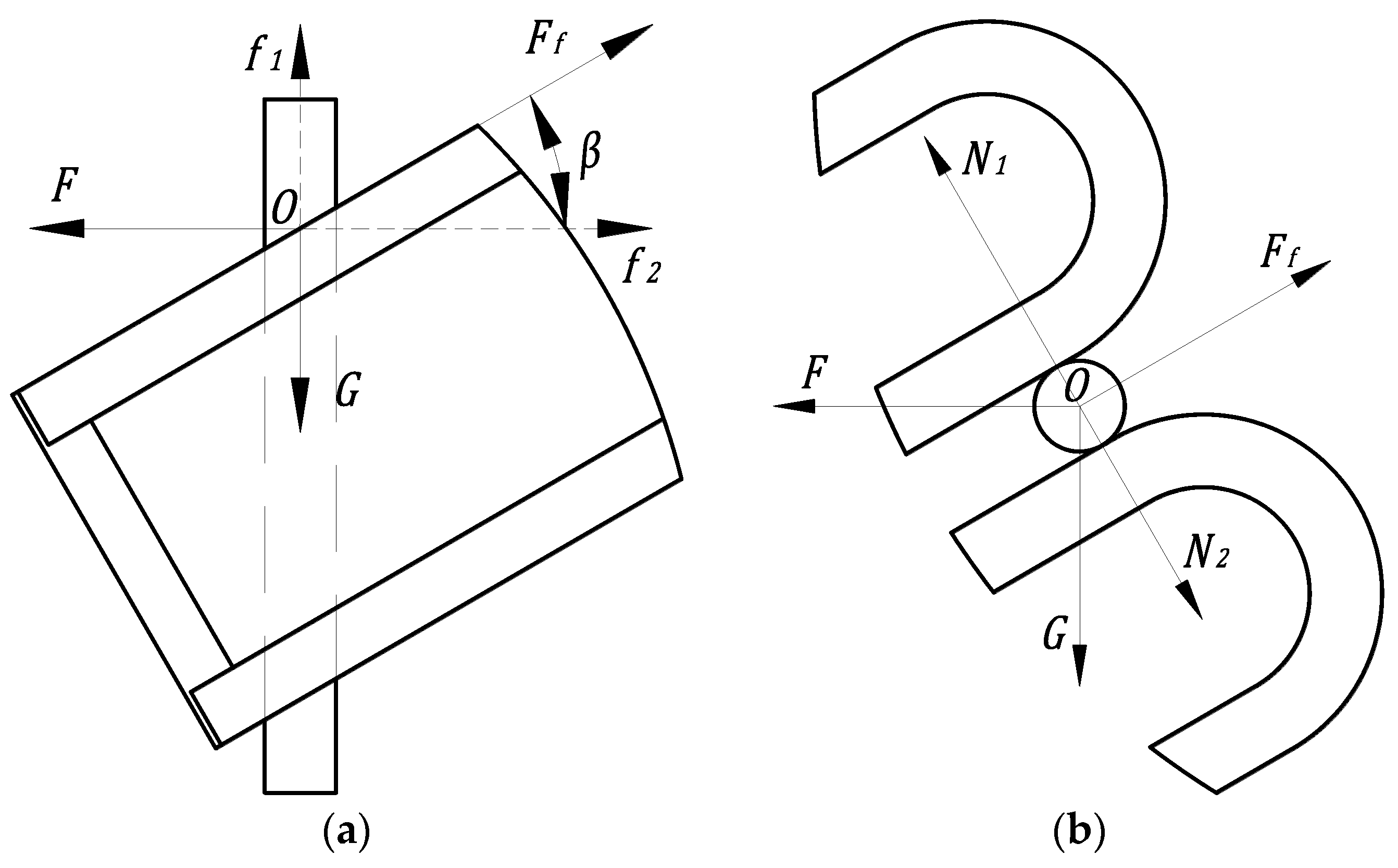
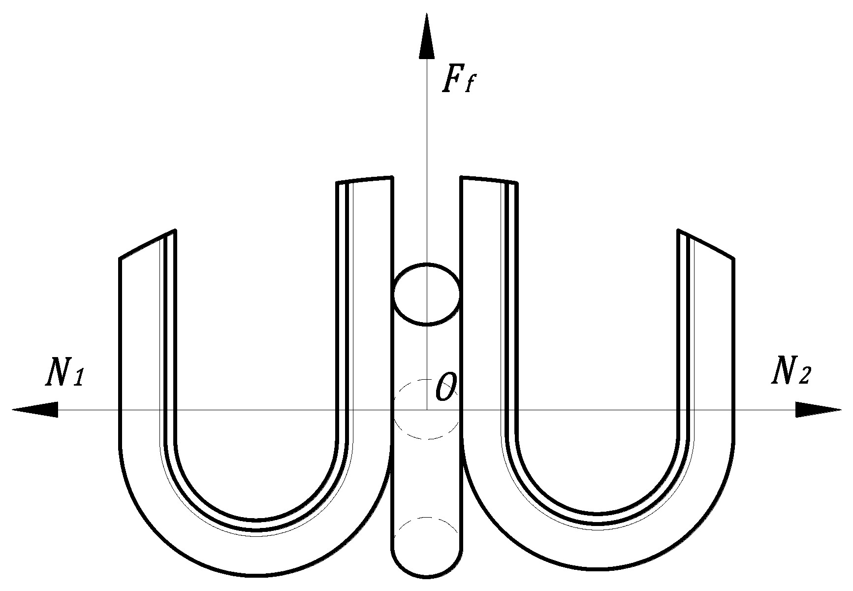
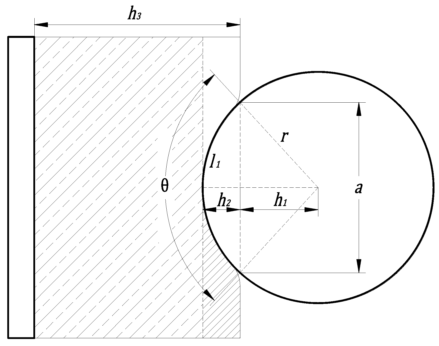
2.4.2. Mechanical Analysis of Stalk Clamping and Conveying

Too much clamping force may cause breakage of rape shoot stalks, while too little clamping force may not achieve the purpose of clamping and transporting. Therefore, force analysis of the two limit positions of feeding and feeding ports during clamping and transport of rape shoots is important.
In Figure 8, F and G represent the working thrust of rape shoots harvester and gravity of rape shoots stalk, respectively; Ff, f1 and f2 represent the friction force during rape shoot stalk holding and conveying, vertical friction force and lateral friction force, respectively; N1 and N2 represent the clamping force of flexible sponge on rape shoots stalks and O represents the center of mass of rape shoots stalks. The force on the center of mass satisfies the following relationship if the stalk enters the clamping device vertically:
f 1 = G = F f   ×   sin β
f 2 = F = F f   ×   cos β
The stalk in the clamping and conveying process of friction significantly impacts the clamping and conveying device efficiency. The clamping and conveying device should clamp the rape shoots, and the process does not produce any directional slip since the belt rotates upward for transportation. However, the stalk produces slip based on the critical state analysis of the stalk force, where the friction of the stalk and the pressure generated by the flexible sponge are proportional to the stalk cross-sectional forces. The force schematic is shown in Figure 9.
The gravity of the stalk starts to act on the flexible sponge of the lower belt when the rape shoot stalks change from vertical to horizontal position. As a result, the upward clamping force of the flexible sponge on the rape shoots gradually increases compared with the downward clamping force of the flexible sponge on the plants. The required clamping force of rape shoots at the feeding port is the maximum value of the clamping and conveying stage. The subsequent clamping and conveying process can ensure that the rape shoots do not slip in any direction and smoothly complete the clamping and conveying operation if the clamping force of the rape shoots at the feeding port ensures that the plants do not slip in any direction.
Herein, the rape shoots vertically clamped in the feed opening were used for analysis. The clamping force N1 and N2 of flexible sponge on the stalk is a pair of equilibrium forces. The clamping force on the rape shoots stalk should satisfy the following equation to ensure that the rape shoots do not slip during the clamping and conveying process and avoid damage to plants:
N max     N 1     G μ sin β
where Nmax and G represent the clamping breaking force (N) and gravity of rape shoots stalk (N), respectively.
The clamping force on the stalk and the pressure on the flexible sponge represent the action and reaction forces based on Newton’s third law. The magnitude of the above action and reaction forces are related to the flexible sponge deformation variables. The state of the stalk in the clamping process is shown in Figure 10.
The flexible sponge of the right-end belt should be set to the middle-hollow state to ensure normal unloading of the stalks at the discharge port. Additionally, the fit of rape shoots with the flexible sponge should also be reduced instantly when the stalk passes through the discharge port to ensure that the shoots do not continue to rotate with the belt and that they can be unloaded smoothly. The area where the stalk is held by the flexible sponge during the clamping and conveying process has two sections with a height of h4. The deformation state of the stalk cross-section in the clamping and conveying state with the flexible sponge was selected for further analysis. The flexible sponge deformation state is shown in Figure 11.
r, h1, h2 and h3 represent radius of rape shoots stalk, half of the distance between two flexible sponges in the clamped state, depth of rape shoot stalks pressed into the flexible sponge and thickness of the flexible sponge, respectively; a, θ and l1 represent the chord length corresponding to the stalk pressed into the part, the angle corresponding to the stalk pressed into the part and arc length corresponding to the stalk pressed into the part, respectively. The part of the stalk section pressed into the flexible sponge forms a bow during plant clamping and conveying. In this study, the pressed-in part was assumed to be rectangular corresponding to the bow, to simplify analysis. The sponge force direction was defined as the opposite direction of the pressed-in sponge, and was calculated as shown below:
N 1 = F h = σ S = E ε S = 2 aEh 2 h 4 h 3 = 4 rEh 2 h 4 2 1 - cos θ h 3
where Fh, σ, S, E and ε represent the internal force on the flexible sponge (N), stress on the flexible sponge (MPa), area of action of the stress (mm2), elastic modulus of the flexible sponge (MPa) and strain on the flexible sponge, respectively.
In this study, E, h4 and h3 were 0.36 MPa, 40 mm and 30 mm, respectively. Notably, the depth of the rape shoot stalk pressed into the flexible sponge increases with increasing the angle of the pressed part and thus increases the clamping force on the rape shoot stalks. The gripping and transporting device must ensure that the plant with the smallest stalk diameter can be gripped and transported by the device, and the plant with the largest stalk diameter will not be damaged during the transporting process. The range of rape shoot stalk pressed into the depth of the flexible sponge and the range of the clamping and conveying distance of the device were obtained based on a previous study on stalk diameter and a radial compression test with the parallel vertical 9 and Equation (10). The clamping and conveying distance was set at 5–20 mm after the calculation.

3. Tests and Results

3.1. Test Materials and Equipment of Indoor Bench Test

A bench test was conducted to test and optimize the overall performance of the prototype of the trial harvester. The sampling area was Anxiang County, Changde City, Hunan Province, and the sampling variety was “Changxiangtai 603” (plant height after harvesting: 490 mm). The bench test was conducted at the Agricultural Mechanization Engineering Training Center of Hunan Agricultural University. The harvested rape shoots were inserted into the fixture shown in Figure 12 (the height of the fixture chassis was 300 mm above the ground). A hollow tubular steel pipe was then installed on the fixture to fix rape shoots and simulate the growth pattern of rape shoots in the field. The device was fixed to one end of the TCC-2.4 soil tank test bench. The movement of the soil tank test bench causes relative displacement between the rape shoots plant in the fixed device and the rape shoots harvester to simulate the field rape shoots harvesting operation.

3.2. Test Method and Evaluation Index

The forward speed of the machine, the speed of the clamping belt and the clamping gap significantly affect the performance of the rape shoot harvester based on the preliminary structural design and theoretical analysis. In this study, the soil tank test vehicle speed was adjusted to change the forward speed of the machine. The clamping belt conveying speed was also adjusted by controlling the hydraulic throttle valve. The position of the tension nut in the clamping conveyor belt tensioning and clamping distance adjustment device were adjusted to alter the clamping gap. The missed cut rate, missed clamp rate and plant damage rate of rape shoots were used as the evaluation indexes of the performance of the harvester based on previous studies [24,25]. The missed cut rate was calculated as follows:
Q = Q 1 Q Z   ×   100 %
where Q, Q1 and QZ represent missed cut rate, number of missed cuts (pieces) and total number of missed cuts (pieces), respectively.
The missed clamp rate was calculated as follows:
J = J 1 J Z   ×   100 %
where J, J1 and JZ represent missed clamp rate, number of missed clamps (pieces) and total number of missed clamp clips (pieces), respectively.
The plant damage rate of rape shoots was calculated as follows:
P = P 1 Z   ×   100 %
where P, P1 and Z represent plant damage rate of rape shoots, number of damaged rape shoots (one) and total number of rape shoots that finished the cutting and clamping and conveying operation (one), respectively.

3.3. Single-Factor Tests Affecting the Harvesting Quality of Rape Shoots

A single-factor test was conducted to investigate the effects of different parameters (the forward speed of machine, clamping belt speed and clamping gap) on the performance of the harvester based on the missed cut rate, missed clamp rate and plant damage rate of rape shoots (as evaluation indicators).

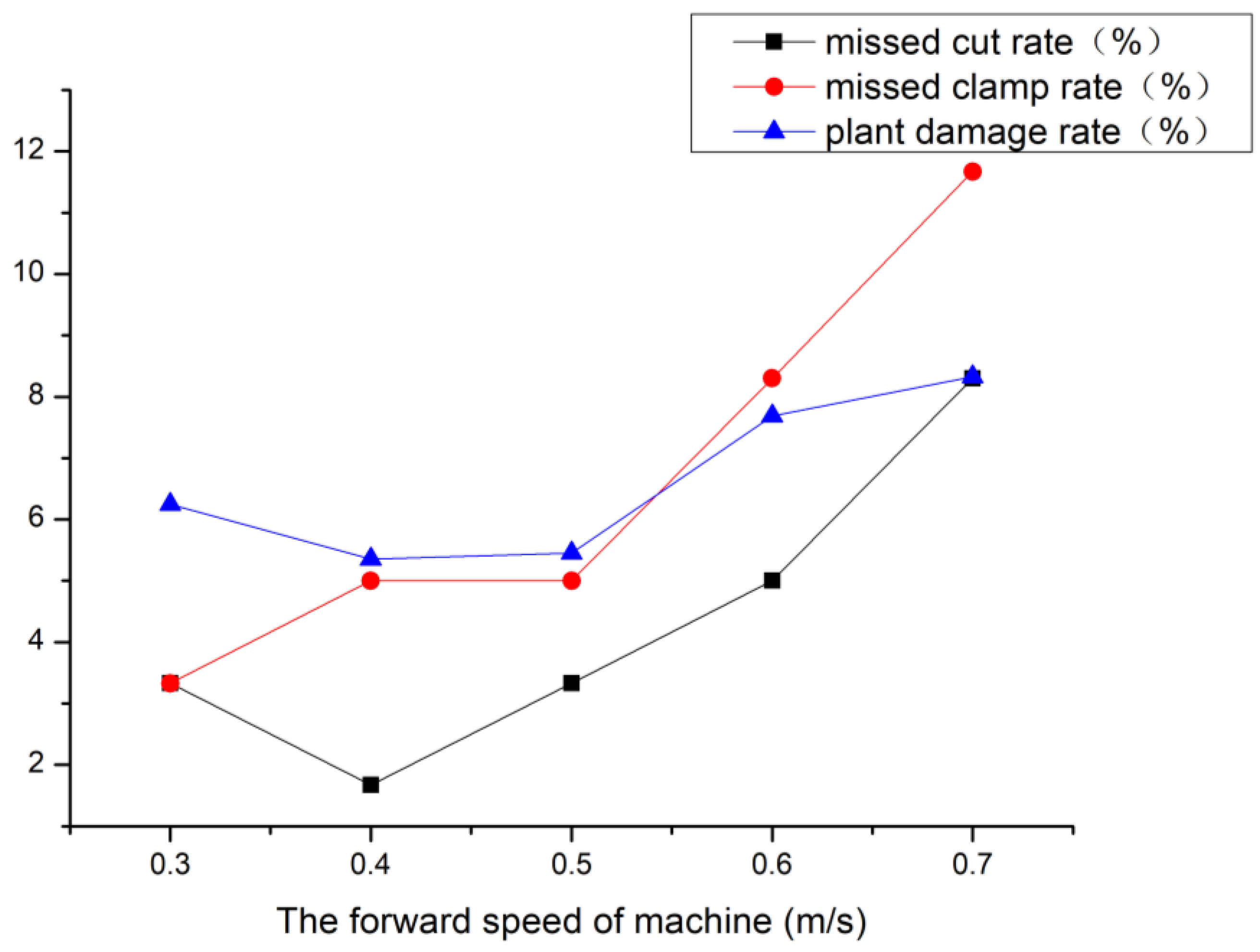
3.3.1. Influence of Forward Speed of Machine on Harvesting Quality

The clamping belt speed and the clamping gap were set at 0.9 m/s and 12 mm, respectively, to assess the effect of the forward speed of the machine on harvesting quality. The test was repeated thrice at each forward speed of the machine (0.3 m/s, 0.4 m/s, 0.5 m/s, 0.6 m/s and 0.7 m/s) using 20 rape shoots in each group (Figure 13).
The missed cut rate decreased first and reach the lowest value at 0.4 m/s, then increased with increasing the forward speed of the machine. Low forward speed had less influence on the missed cut rate. The cutting blank area gradually increased with increasing the forward speed of the cutting tool, which leads to missing cutting. The missed clamp rate increases with the forward speed of machine, and it changes obviously at higher speed. The increase in the forward speed leads to the accumulation of rape shoots in the feed port after cutting, resulting in a certain amount of missed clamp. The plant damage rate first decreased and reached the lowest point at 0.4~0.5 m/s, then increased with increasing forward speed. The rape shoots accumulate in the feed port and slowly slide downward when the forward speed is larger. As a result, the cutter repeatedly cuts the plants, thus increasing the plant damage rate.

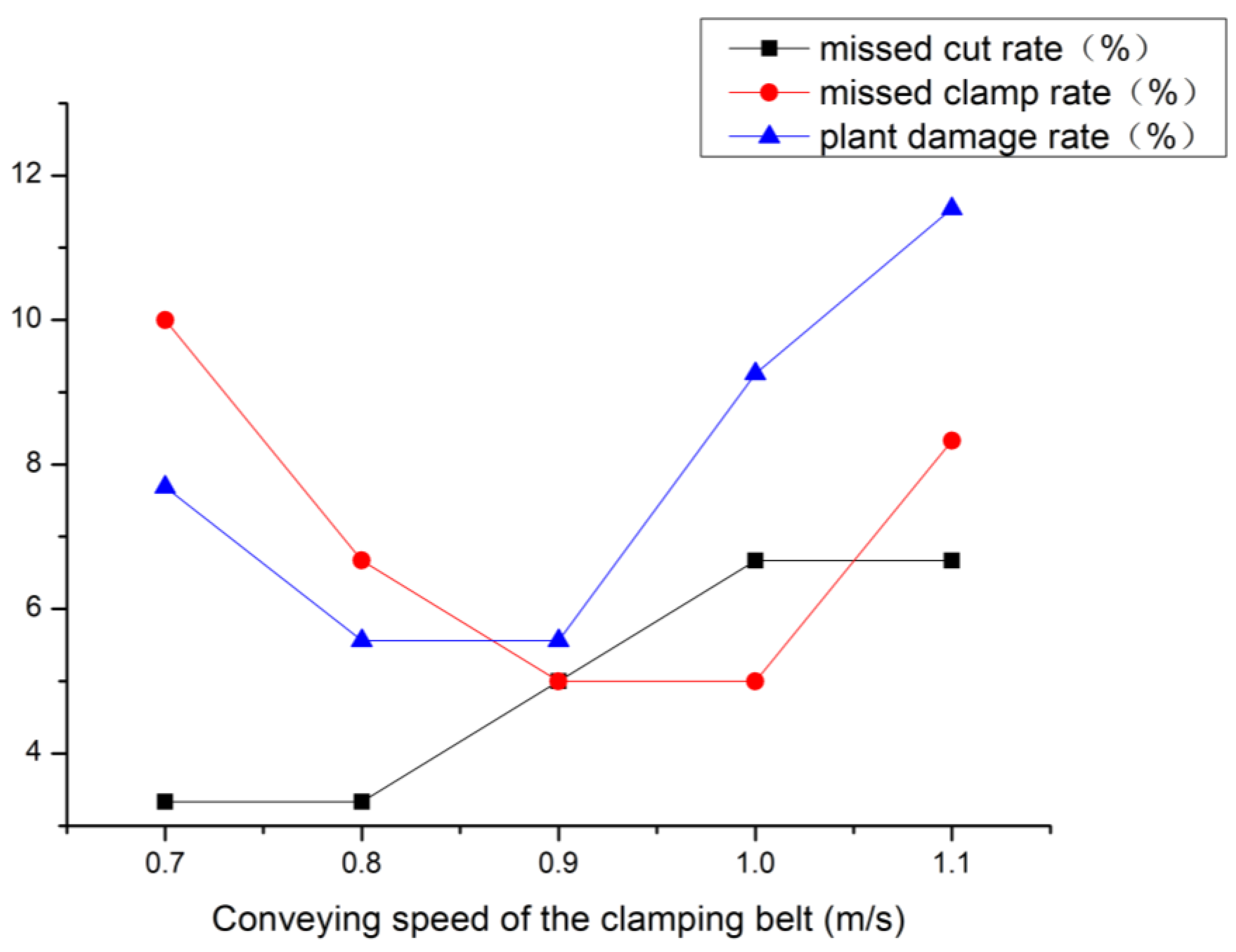
3.3.2. Influence of Clamping Belt Conveying Speed on Harvesting Quality

The forward speed of the machine and the clamping gap were set at 0.5 m/s and 12 mm, respectively, to assess the influence of the clamping belt conveying speed on harvesting quality. The test was repeated thrice at each level of clamping belt conveying speed (0.7 m/s, 0.8 m/s, 0.9 m/s, 1.0 m/s and 1.1 m/s) using 20 rape shoots in each group (Figure 14).
The missed cut rate gradually increased with increasing the clamping belt conveying speed. The missed clamp rate first decreased and reached the lowest value at 0.9~1.0 m/s, then increased with increasing speed of the device. A few rape shoots accumulate at the feed port after cutting when the clamping speed is low, thus increasing the missed clamp rate, and the vibration of the harvester will be increased when the clamping speed is too high, thus affecting the clamping efficiency. The plant damage rate also first decreased and reached the lowest value at 0.8~0.9 m/s, then increased with increasing clamping and conveying speed. The device produces a larger impact on the plant during clamping when the clamping and conveying speed is larger, thus significantly increasing the plant damage rate.

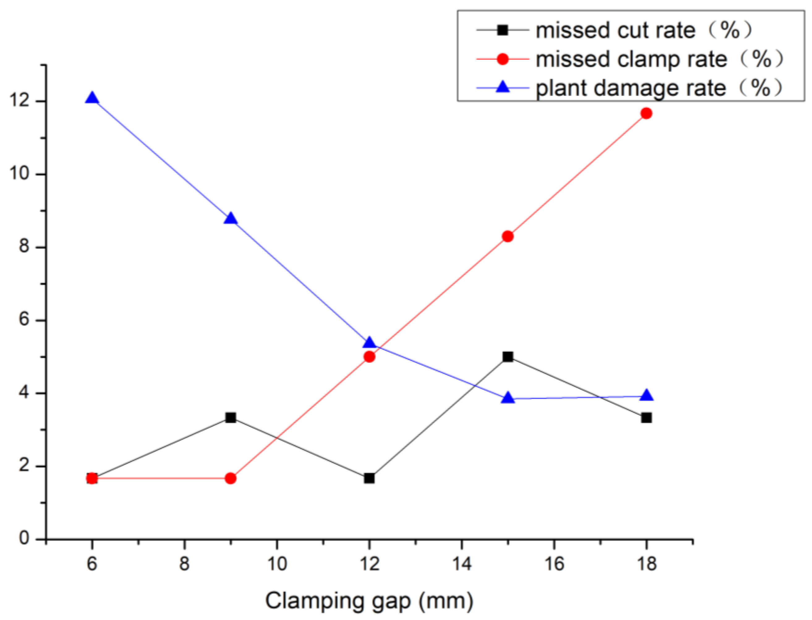
3.3.3. Effect of Clamping Gap on Harvesting Quality

The forward speed of the machine and the conveying speed of the clamping belt were set at 0.5 m/s and 0.9 m/s, respectively, to assess the effect of clamping gap on harvesting quality. The test was repeated thrice at each level of clamping gap (6 mm, 9 mm, 12 mm, 15 mm and 18 mm) using 20 rape shoots in each group (Figure 15). The clamping gap did not significantly affect the missed cut rate. The missed clamp rate gradually increased with increasing the clamping gap. The plant damage rate gradually decreased with increasing the clamping gap.

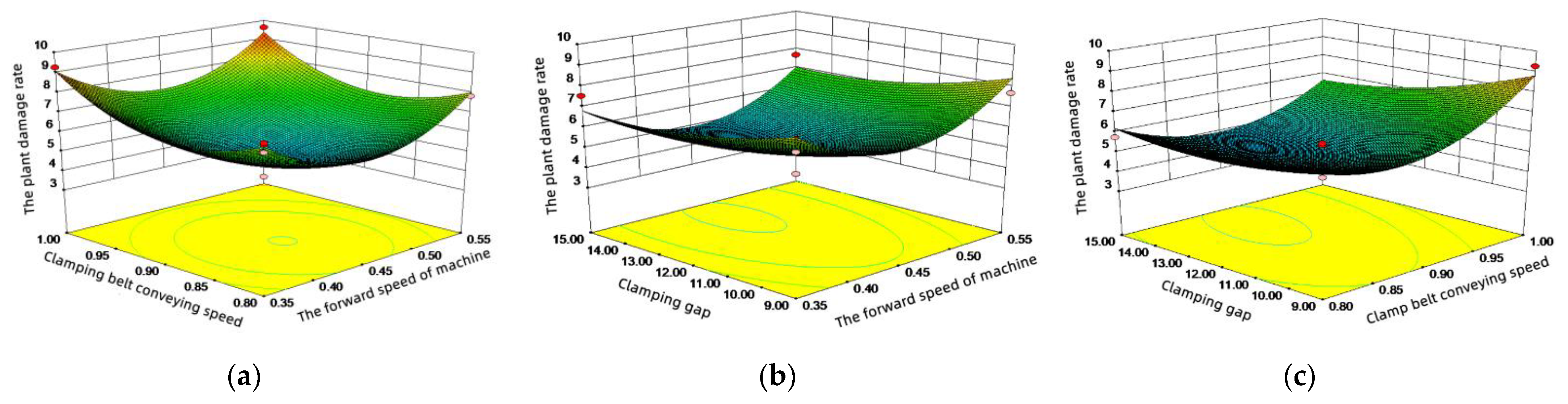
3.4. Response Surface Synthesis Analysis of Rape Shoot Harvesting Quality

The single-factor test showed that the forward speed of the machine, the conveying speed of the clamping belt, and the clamping gap each could affect the performance of the rape shoots harvester. Although the optimal working interval for each factor was determined, each factor interacts with each other during the actual operation, and thus a combined optimal condition is necessary. Therefore, a response surface test was conducted to obtain the regression equation for the harvesting performance of the device to obtain the optimal combination of operating parameters.

3.4.1. Experimental Design and Results

Based on the single-factor test, the forward speed of the machine X1, clamping belt conveying speed X2 and clamping gap X3 were selected as the test factors, and the missed cut rate Y1, missed clamping rate Y2 and plant damage rate Y3 were chosen as the evaluation indexes in the response surface BBD (Box–Behnken Design) test using Design-Expert 8.0.6 software. The coding table is presented in Table 4.
The quadratic regression orthogonal test protocol and results obtained using the Design-Expert 8.0.6 software in line with the test factor level coding table are shown in Table 5.
The test results were analyzed by ANOVA, and the results are presented in Table 6. The data show that the P values of the regression models of missed cut rate, missed clamp rate and plant damage rate were below 0.05, suggesting that they were significant and that the model was valid. The P values of its misfit terms were all insignificant, indicating that the model had a good fit.
The regression equation of each factor with the missed cut rate Y1, missed clamp rate Y2 and plant damage rate Y3 were calculated by excluding the insignificant coefficient of influence in the regression equation based on the ANOVA analysis results.
Y 1 = 3 + 1 . 67 X 1 + 1 . 93 X 1 2 Y 2 = 5   -   1 . 04 X 2   + 1 . 25 X 3 + 1 . 46 X 3 2 Y 3   = 5 . 06 + 1 . 98 X 1 2 + 1 . 49 X 2 2
The regression results demonstrate that the influence of the forward speed of the machine X1, clamping belt conveying speed X2, clamping gap X3 on the missed cut rate Y1 were, in descending order of significance, forward speed of the machine X1, clamping belt conveying speed X2, clamping gap X3; on the missed clamp rate Y2 were, in descending order of significance, clamping gap X3, clamping belt conveying speed X2, forward speed of the machine X1; on the plant damage rate Y3 were, in descending order of significance, clamping belt conveying speed X2, clamping gap X3, and forward speed of the machine X1. The plant damage rate is often used to evaluate the quality of rape shoots, and corresponding surface plots were constructed according to the regression results to determine the influence law of each test factor on plant damage rate, as shown in Figure 16.
It can be seen from Figure 16a that the clamping gap is at the central level. When the clamping belt conveying speed is constant, the plant damage rate first decreases and then increases with the increase in the forward speed; when the forward speed of the machine is fixed, the plant damage rate first decreases and then increases with the increase in the belt conveying speed. As shown in Figure 16b, when the central value of clamping belt conveying speed was selected and the forward speed of the machine was fixed, the plant damage rate was negatively correlated with the clamping gap. When the clamping gap was fixed, the plant damage rate decreased first and then increased with increasing forward speed. As shown in Figure 16c, when the central value of the forward speed of the machine was selected and the clamping belt conveying speed was fixed, the plant damage rate was negatively correlated with the clamping gap; when the clamping gap was fixed, the plant damage rate first decreased and then increased with the increase in the clamping belt conveying speed.

3.4.2. Parameter Optimization

The results were optimized by setting the minimum values of the missed cutting rate, missed clamping rate and plant breakage rate in Numerical using the Optimization module of Design-Expert 8.0.6 software. The results were analyzed and solved, the optimal efficiency of the machine was obtained at a forward speed of 0.42 m/s, a speed of the clamping belt of 0.89 m/s and a clamping gap of 11.43 mm, with a missed cut rate of 2.63%, a missed clamp rate of 4.84% and a plant damage rate of 5.22%.

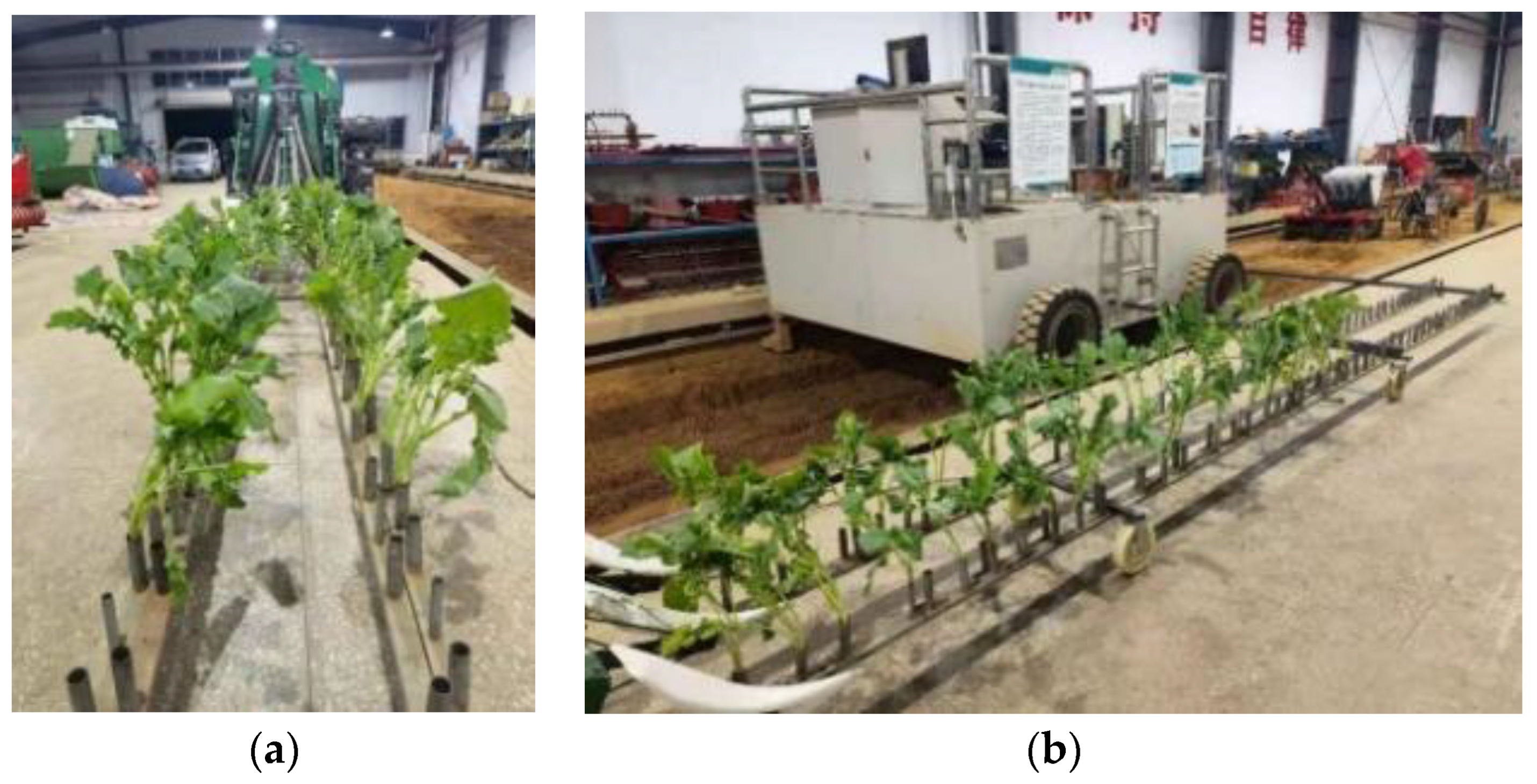
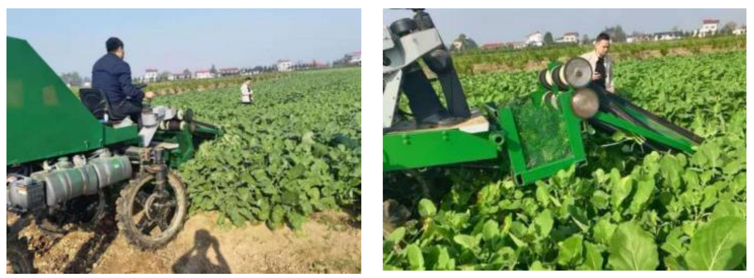
3.5. The Field Trial

To verify the reliability of the optimized results, a field trial was conducted under the optimal working parameters, and the field tests are shown in Figure 10. Anxiang County, Changde City, and Hunan Province were selected as the test sites, and 60 rape shoots were selected from the front end of each ridge. The plants at the back end of the selected rape shoots were removed to play a dividing role. The machine traveled to the boundary to stop the operation, and the test was repeated five times. The obtained test results are presented in Table 7.
When the machine was working in the field with a forward speed of 0.42 m/s, a clamping belt conveying speed of 0.89 m/s and a clamping gap of 11.43 mm, the missed cut rate was 2.67%, the missed clamp rate was 5.33% and the plant breakage damage rate of rape shoots was 5.41%. The deviation of the field test results from the theoretical optimized parameters was 0.04%, 0.49% and 0.19%, respectively, indicating that the optimized scheme was effective (Figure 17). The field test results deviated from the theoretical optimized parameters by 0.04%, 0.49% and 0.19%, suggesting that the optimized scheme was effective and the rape shoots harvester designed here showed good field performance.

4. Discussion

Through the preliminary optimization and experimental verification, the harvest of rape shoots developed in this paper can better complete the mechanized harvest of rapeseed stems and achieve low damage flexibility harvesting. However, by comparing the rape shoot harvester with the world’s advanced harvesters for harvesting other varieties, there are still some limitations. There is still room for improvement in the functional comprehensiveness of the rape shoot harvester developed in this paper. The versatility needs to be improved, and the degree of intelligence is low.
In the subsequent improvement and optimization process, the rape shoot baling and packaging device should be added after the discharge port of the machine to realize the function of cutting, conveying and packaging through a rape shoot harvester. The research on the material characteristics of more varieties of rape shoots should be strengthened to improve the efficiency of agricultural machinery and agronomy and improve the versatility of the rape shoots harvester. The height adjustment system of the header is added in order to not affect the working parameters of the adjusted header, so as to ensure the working efficiency of the machine in different field terrains and when growing different rape shoot plants. Combined with the intelligent system for optimization, a visual recognition system can be installed to adjust the height of the cutting device in real time according to the growth of the rape shoot in the field, and combined with 3S technology to achieve unmanned operation in the field.

5. Conclusions

Based on the current situation of the low mechanization degree of rape shoots harvesting, this paper, combined with the study of the characteristics of rape shoots material, designed a rape shoots harvester. The harvester can complete the orderly and low-loss flexible harvesting of rape shoots in the field. The structure design and working parameter optimization of the cutting device and flexible clamping and conveying device are mainly carried out in this paper. The specific research content is as follows:
(1)
The forward speed of the machine, the speed of the clamping belt and the clamping gap were selected as the test factors, and the missed cut rate, missed clamp rate and plant damage rate were used as the evaluation indexes in the single-factor tests of the rape shoots harvester. The results show that the harvester has a good working effect when the forward speed of the machine is in the range of 0.35~0.55 m/s, the conveying speed of the clamping belt is in the range of 0.8~1.0 m/s and the clamping gap is in the range of 9~15 mm.
(2)
Design-expert 8.0.6 software was used for response surface synthesis analysis design and data optimization, and the optimal working parameters of the rape shoots were a machine forward speed of 0.42 m/s, clamping belt speed of 0.89 m/s and 11.43 mm clamping gap, which resulted in a 2.63% missed cut rate, 4.84% missed clamp rate and 5.22% plant damage rate. The field validation tests showed that the rape shoots were cut effectively and transported stably.

Author Contributions

Conceptualization, D.X. and H.L.; methodology, D.X.; software, W.X.; validation, W.X.; investigation, D.X.; resources, M.W.; data curation, H.L.; writing—original draft preparation, D.X. and H.L.; writing—review and editing, M.W. and H.L.; visualization, H.L.; supervision, H.L.; funding acquisition, M.W. All authors have read and agreed to the published version of the manuscript.

Funding

This research was funded by National Key R&D Program of China, grant number 2022YFD2300103. Teaching Reform Research Project of Universities in Hunan Province, grant number HNJG-2020-0302. Excellent Postgraduate Courses in Hunan Province in 2019, grant number N178.

Institutional Review Board Statement

Not applicable.

Informed Consent Statement

Not applicable.

Data Availability Statement

All data are presented in this article in the form of figures and tables.

Conflicts of Interest

The authors declare no conflict of interest.

References

  1. Liu, Q.; Ren, T.; Zhang, Y.; Li, X.; Cong, R.; Liu, S.; Fan, X.; Lu, J. Evaluating the application of controlled release urea for oilseed rape on Brassica napus in a regional scale: The optimal usage, yield and nitrogen use efficiency responses. Ind. Crops Prod. 2019, 140, 111560. [Google Scholar] [CrossRef]
  2. Songchao, Z.; Chen, C.; Jiqiang, L.; Tao, S.; Xiaoming, L.; Yong, T.; Xinyu, X. The Airflow Field Characteristics of the Unmanned Agricultural Aerial System on Oilseed Rape (Brassica napus) Canopy for Supplementary Pollination. Agronomy 2021, 11, 2035. [Google Scholar]
  3. Wan, X.; Liao, Q.; Liao, Y.; Ding, Y.; Zhang, Q.; Huang, H.; Chen, H.; Zhu, L. Situation and Prospect of Key Technology and Equipment in Mechanization and Intelligentization of Rapeseed Whole Industry Chain. J. Huazhong Agric. Univ. 2021, 40, 24–44. [Google Scholar]
  4. Zhang, Z.; Yin, Y.; Liu, F.; Wang, J.; Fu, Y. Current Situation and Development Countermeasures of Chinese Rapeseed Multifunctional Development and Utilization. Chin. J. Oil Crop Sci. 2018, 40, 618–623. [Google Scholar]
  5. Liao, Y.; Liao, Q.; Zhou, Y.; Wang, Z.; Jiang, Y.; Liang, F. Parameters Calibration of Discrete Element Model of Fodder Rape Crop Harvest in Bolting Stage. Trans. Chin. Soc. Agric. Mach. 2020, 51, 73–82. [Google Scholar]
  6. Liao, Y.; Li, Y.; Wan, X.; Liao, Q.; Shan, Y.; Meng, Z. Design and Experiment of Gantry Type Electric Drive Rapeseed Stalks Harvester. Trans. Chin. Soc. Agric. Mach. 2022, 53, 147–159. [Google Scholar]
  7. Wenqi, W.; Yidong, M.; Longsheng, F.; Yongjie, C.; Yaqoob, M. Physical and Mechanical Properties of Hydroponic Lettuce for Automatic Harvesting. Inf. Process. Agric. 2020, 8, 550–559. [Google Scholar]
  8. Hachiya, M.; Amano, T.; Yamagata, M.; Kojima, M. Development and Utilization of a New Mechanized Cabbage Harvesting System for Large Fields. Jpn. Agric. Res. Q. JARQ 2004, 38, 97–103. [Google Scholar] [CrossRef] [Green Version]
  9. Available online: https://www.hortech.it/en/prd/slide-crab/ (accessed on 8 July 2022).
  10. Ibrahim, E.D.M.; Mohamed, E.S.A. Fabrication and Evaluation of a Cabbage Harvester Prototype. Agriculture 2020, 10, 631. [Google Scholar]
  11. Liu, D.; Xiao, H.; Jin, Y.; Yang, G.; Liu, M. Design and Experiment of the Orderly Harvester of Chinese Little Greens. Int. Agric. Eng. J. 2018, 27, 295–306. [Google Scholar]
  12. Shi, Y.; Zhang, Y.; Wang, X.; Morice, O.; Sun, G. Design of Orderly Harvester in Stems-leafy Vegetables Based on Pro/E. J. Agric. Mech. Res. 2017, 39, 139–143. [Google Scholar]
  13. Zhang, J.; Wang, J.; Du, D.; Long, S.; Wang, Y.; You, X. Design and Experiment of Crawler Self-propelled Single-row Harvester for Chinese Cabbage. Trans. Chin. Soc. Agric. Mach. 2022, 53, 134–146. [Google Scholar]
  14. Sarkar, P.; Raheman, H. A Comprehensive Review of Mechanized Cabbage Harvesting Systems and Its Present Status in India. J. Inst. Eng. India Ser. A 2021, 102, 861–869. [Google Scholar] [CrossRef]
  15. Guan, Z.; Wu, C.; Wang, G.; Li, H.; Mu, S. Design of Bidirectional Electric Driven Side Vertical Cutter for Rape Combine Harvester. Trans. Chin. Soc. Agric. Eng. 2019, 35, 1–8. [Google Scholar]
  16. Mitsuhashi, T.; Chida, Y.; Tanemura, M. Autonomous Travel of Lettuce Harvester using Model Predictive Control. IFAC PapersOnLine 2019, 52, 155–160. [Google Scholar] [CrossRef]
  17. Liu, D.; Xiao, H.; Jin, Y. Research Status and Development Countermeasures of Orderly Harvesting Machine of Leaf Vegetables. Jiangsu Agric. Sci. 2019, 47, 27–31. [Google Scholar]
  18. Wang, W.; Lv, X.; Wang, S.; Lu, D.; Yi, Z. Current Status and Development of Stem and Leaf Vegetable Mechanized Harvesting Technology. J. China Agric. Univ. 2021, 26, 117–127. [Google Scholar]
  19. GB/T 5262-2008; Measuring Methods for Agricultural Machinery Testing Conditions. General Rules. Standardization Administration of the P.R.C.: Beijing, China, 2008; Volume 3.
  20. Liao, Y.; Wang, Z.; Liao, Q.; Wan, X.; Zhou, Y.; Liang, F. Calibration of Discrete Element Model Parameters of Forage Rape Stalk at Early Pod Stage. Trans. Chin. Soc. Agric. Mach. 2020, 51, 236–243. [Google Scholar]
  21. Wang, W. Design and Tests Study of Celery Harvester. Master’s Thesis, Zhejiang Sci-Tech University, Hangzhou, China, 2021. [Google Scholar]
  22. Liu, D. Optimization Design and Experimental Study on Key Components of Orderly Harvester of Chinese Little Greens. Master’s Thesis, Chinese Academy of Agricultural Sciences, Beijing, China, 2019. [Google Scholar]
  23. Bin, Z.; Haolu, L.; Jicheng, H.; Kunpeng, T.; Cheng, S.; Xianwang, L.; Xingsong, W. Ramie Field Distribution Model and Miss Cutting Rate Prediction Based on the Statistical Analysis. Agriculture 2022, 12, 651. [Google Scholar]
  24. Hu, M. Design and Experimental Study of Test Bench of Spinach Mechanical Harvesting. Master’s Thesis, Shandong Agricultural University, Taian, China, 2016. [Google Scholar]
  25. Yao, S. Optimal Design and Experimental Research on Key Components of Cabbage Harvester. Master’s Thesis, Chinese Academy of Agricultural Sciences, Beijing, China, 2020. [Google Scholar]
Figure 1. Schematic diagram of the key structure of the rape shoots harvesting device: 1. cutting device; 2. crop divider; 3. suppression wheel; 4. flexible clamping conveyor belt; 5. synchronous transmission gear; 6. discharge port; 7. clamping belt power input shaft; 8. frame; 9. separation partition; 10. belt tensioning and clamping spacing adjustment device; 11. feeding port.
Agriculture 13 00792 g001
Figure 2. Rape shoot harvesting.
Agriculture 13 00792 g002
Figure 3. Mechanical properties of rape shoot stalks: (a) the axial compression mechanical properties; (b) the radial compression mechanical properties; (c) the shear mechanical properties.
Agriculture 13 00792 g003
Figure 4. Mechanical properties curve of the rape shoot stalk: (a) stalk axial compression characteristic curve; (b) radial compression characteristic curve of stalk; (c) stalk shear characteristic curve.
Agriculture 13 00792 g004
Figure 5. Schematic of the clamped stalk.
Agriculture 13 00792 g005
Figure 6. Cutting diagram with different rate ratios: (a) λ = 1.0; (b) λ = 0.8; (c) λ = 0.6.
Agriculture 13 00792 g006
Figure 7. Rape shoot stalk transport status.
Agriculture 13 00792 g007
Figure 8. Clamping and conveying force diagram of rape shoot stalks: (a) the feeding port; (b) the discharge port.
Agriculture 13 00792 g008
Figure 9. Schematic of the cross-sectional forces of rape shoot stalks.
Agriculture 13 00792 g009
Figure 10. Stalk clamping state of rape shoots: (a) overall status; (b) local status.
Agriculture 13 00792 g010
Figure 11. Flexible sponge deformation state.
Agriculture 13 00792 g011
Figure 12. Bench test operation diagram: (a) front view; (b) side view.
Agriculture 13 00792 g012
Figure 13. Influence of machine forward speed on harvesting performance.
Agriculture 13 00792 g013
Figure 14. Effect of clamping belt conveying speed on harvesting performance.
Agriculture 13 00792 g014
Figure 15. Effect of clamping gap on harvesting performance.
Agriculture 13 00792 g015
Figure 16. Effect of test factors on plant damage rate: (a) X3 = 12 mm; (b) X2 = 0.9 m/s; (c) X1 = 0.45 m/s.
Agriculture 13 00792 g016
Figure 17. The field test.
Agriculture 13 00792 g017
Table 1. Main technical parameters of rape shoot harvesting machine.
ParameterValue
Dimension/m × m × m1.2 × 5.5 × 2.2
Drive modeHydraulic (System pressure 14 MPa)
Working width/mm1000
Operating speed/km·h−10~3
Cutter typeReciprocating double-action knife
Operating efficiency/ha·h−10.36
Number of flexible clamping conveyors2
Table 2. Planting parameters of rape shoots.
ParameterValue
Ridge width/mm600
Furrow depth/mm≤300
Number of plant rows per ridge2
Sowing methodDrilling
Plant row spacing/mm350
Table 3. Basic physical parameters of rape shoots.
Statistical IndicatorsCrop Natural Height
mm
Plant Weight
g
Plant Height after Cutting
mm
Diameter at Cut
mm
Stem Static Friction
Factor
Stalk Density
g·cm−3
Mean value793116.1548813.40.751.04
Maximum value876171.1853215.50.841.15
Minimum value67564.9945811.20.681.01
Standard deviation69.230.9420.431.290.040.04
Coefficient of variation0.090.260.040.100.050.04
Table 4. Code schedule of factors and levels.
LevelsFactor
The Forward Speed of Machine
X1/m/s
Clamping Belt Conveying Speed
X2/m/s
Clamping Gap
X3/mm
−10.350.89
00.450.912
10.551.015
Table 5. Experimental scheme and results.
Experimental NumberExperimental FactorExperimental Index
The Forward Speed of Machine
X1/m/s
Clamping Belt Conveying Speed
X2/m/s
Clamping Gap
X3/mm
Missed Cut Rate
Y1/%
Missed Clamp Rate
Y2/%
Plant Damage Rate
Y3/%
10.450.9012.003.3355.45
20.550.909.006.676.677.69
30.450.9012.001.6755.36
40.450.8015.003.33105.77
50.451.009.00559.26
60.450.9012.0053.335.45
70.450.809.003.336.677.41
80.351.0012.00559.26
90.350.8012.003.336.677.41
100.451.0015.0058.335.77
110.550.8012.006.678.337.84
120.350.909.003.3357.27
130.551.0012.008.3359.62
140.550.9015.006.676.677.69
150.350.9015.003.338.337.55
160.450.9012.001.6755.36
170.450.9012.003.336.673.7
Table 6. Analysis of variance results.
Variance SourceQualified Index A/%Replay Index D/%Missing Index M/%
Sum of SquareDegree of FreedomMean SquareF Valuep ValueSum of SquareDegree of FreedomMean SquareF Valuep ValueSum of SquareDegree of FreedomMean SquareF Valuep Value
Model47.5195.284.760.025839.7394.414.040.039637.0894.124.510.0298
X122.28122.2820.110.00290.3510.350.320.58980.2310.230.250.6328
X25.5615.565.020.06008.6918.697.960.02573.7513.754.110.0823
X30.00010.0000.0001.000012.48112.4811.420.01182.9412.943.220.1159
X1X22.5 × 10−512.5 × 10−52.256 × 10−50.99630.6910.690.630.45331.2 × 10−311.2 × 10−31.3 × 10−30.9718
X1X30.00010.0000.0001.00002.7712.772.540.15520.02010.0200.0210.8877
X2X30.00010.0000.0001.00000.00010.0000.0001.00000.8610.860.940.3654
X1214.16114.1612.780.00900.1810.180.170.694216.56116.5618.120.0038
X224.2014.203.790.09264.5714.574.180.08029.2919.2910.170.0153
X320.1210.120.110.75538.9618.968.200.02421.0711.071.170.3160
Residual 7.7671.11 7.6571.09 6.3970.91
Lack of Fit 2.5 × 10−538.33 × 10−64.3 × 10−61.00002.0730.690.500.70504.0631.352.320.2169
Pure Error7.7641.94 5.5841.39 2.3340.58
Cor Total55.2616 47.3816 43.4716
Note: significant (0.01 < p < 0.05), highly significant (p < 0.01).
Table 7. Optimization parameter test results.
LevelsMissed Cut Rate
Y1/%
Missed Clamp Rate
Y2/%
Plant Damage Rate
Y3/%
13.333.335.36
256.673.77
31.673.337.02
43.338.335.66
5055.26
Average2.675.335.41
Disclaimer/Publisher’s Note: The statements, opinions and data contained in all publications are solely those of the individual author(s) and contributor(s) and not of MDPI and/or the editor(s). MDPI and/or the editor(s) disclaim responsibility for any injury to people or property resulting from any ideas, methods, instructions or products referred to in the content.

