1. Introduction
A vegetable transplanter is an agricultural machine used to transplant vegetable seedlings from a nursery to a field [
1,
2]. There are two types of vegetable transplanters based on the seedling supply method: semi-automatic and fully automatic. For semi-automatic vegetable transplanters, the operator manually places the seedlings into the seedling cylinder. For fully automatic ones, the seedlings are automatically placed in the seedling cylinder using additional mechanical systems [
3,
4,
5]. Fully automatic vegetable transplanters have high operational speeds with continuous operation, which saves labor. However, their working mechanism is more complicated and has special requirements, such as seedlings of a specific size and the use of special pot trays [
6,
7]. Although semi-automatic vegetable transplanters have limited speed, there are no restrictions on seedling size or pot tray type, and the working mechanism is more straightforward [
8]. Both types are equally important, depending on the type of vegetable cultivation [
9].
Vegetable transplanters are also classified based on the working mechanism of the transplanting device, which is an important component for planting seedlings in soil. Four types of transplanting devices have been developed: wheel, rotary, four-bar-link, and cam types [
10]. The most widely used are the cam and four-bar-link transplanters because of their relatively simple structures and ease of use [
11]. The four-bar-link transplanting device uses four-bar-link mechanisms for planting seedlings, whereas the cam transplanter is characterized by a cam that opens and closes the hopper through contact with the bearing [
10].
Several studies on both types of transplanting devices have been conducted, including analyses of working mechanisms and operational characteristics [
12,
13,
14], modification of the transplanting device to improve performance through simulations [
2,
9], and safety analyses [
11,
15]. In contrast, research on the consumed power for both semi-automatic transplanting devices has yet to be conducted.
Research on the consumed power and load characteristics of agricultural machinery, such as tractors [
16,
17,
18,
19,
20,
21,
22], potato harvesters [
23], plows and rotavators [
24,
25,
26,
27], and other types of transplanters (including two-row riding fully automatic vegetable transplanters [
28,
29,
30] and electric semi-automatic vegetable transplanters [
31,
32]), has been performed. Several studies on the consumed power and load characteristics of two-row riding fully automatic vegetable transplanters have been conducted, including one by Kim et al. [
28], who measured the PTO (Power Take-Off) torque during field operation based on the planting distance. Kim et al. [
29] analyzed the PTO shaft load with respect to the planting distance through load spectra and damage-level calculations. Then, Kim et al. [
30] studied the PTO load spectrum under various working conditions, not only with various planting distances but also with different planting depths. Another type of vegetable transplanter studied for its power requirements is the electric semi-automatic vegetable transplanter. This machine is a modification of the conventional transplanting machine in which the power source, which was initially a conventional internal combustion engine, is changed into an electric motor. Lee et al. [
31] measured the current to calculate and analyze the consumed power according to the planting distance and travel speed. Lim et al. [
32] studied the power requirements of this machine based on the torque and rotational speed of the transplanting axle. Despite all the studies on the power consumed by various types of vegetable transplanters, none have been carried out for conventional semi-automatic cam- and four-bar-link transplanters. Therefore, comparative studies on the consumed power and safety of the two transplanting devices are needed for effective transplanting operations.
The purpose of this study was to analyze and compare the consumed power and safety of cam and four-bar-link semi-automatic vegetable transplanters according to engine speed and planting distance. The specific objectives were (1) to measure the torque, rotational speed, and strains on the corresponding spots of both transplanters, (2) to calculate the consumed power, static safety factor, and fatigue life from the measured data, and (3) to compare the torque and consumed power, static safety factor, and fatigue life for the two transplanters under similar operating conditions.
2. Materials and Methods
2.1. Test Equipment
Two types of vegetable transplanters were used in this study: cam and four-bar-link semi-automatic transplanters, which are mainly used on small farms.
Figure 1 and
Table 1 show the shapes and main specifications, respectively, of the cam semiautomatic vegetable transplanter. The shape and main specifications of the four-bar-link semi-automatic vegetable transplanter are shown in
Figure 2 and
Table 2, respectively. Both types of vegetable transplanters consist of engines, transmissions, control sections, wheels, seeding cylinders, transplanting devices, and molding wheels.
The main difference between the two types is the design and working mechanism of the transplanting device.
Figure 3 shows the transplanting device of cam and four-bar-link types. The four-bar-link type of transplanting device consists of several linkages and a transplanting hopper. In the cam type, the transplanting device consists of a frame, cam, bearing, crank, transplanting hopper, and some linkages. Additional differences exist in the transmission part and plant-spacing control device. The cam type has only one transmission to transmit the power from the engine to the wheel and transplanting device, while the four-bar-link type has (a) a driving transmission to transmit the engine power to the wheel and the planting unit and (b) a transplanting transmission to transmit the power received from the driving transmission to the crank of the four-bar-link mechanism of the transplanting device. The planting distance in the cam type is determined from the set value of the digital plant-spacing control device. The cam transplanter has a distance sensor that can measure the traveling distance of the transplanter. If the travel distance reaches the set planting distance in the digital plant-spacing control device, the transplanting device input shaft operates at a constant rotational speed so that it remains constant for various planting distances. In contrast, in the four-bar-link transplanter, the planting distance is determined by adjusting the number of shift stages of the transplanting transmission using a manual lever, which requires empirical skill to adjust the planting distance precisely. At a constant working speed, if the rotational speed of the input shaft of the transplanting device increases, the transplantation distance decreases.
In general, the working mechanism of a semi-automatic vegetable transplanter is as follows. The operator starts the engine and sets the desired planting distance digitally in the control section (for the cam type) or manually using the lever (for the four-bar-link type). The transplanter moves forward, and the transplanting device moves up and down. The operator places the seedlings manually in the seedling cylinder. The seedling cylinder is opened when the transplanting hopper of the transplanting device is in the top position to place the seedling into the hopper. Then, the transplanting device moves down, and the hopper is opened when it is in the bottom position to plant the seedling in the soil. The transplanting device moves up again, while the molding wheel covers both sides of the planted seedling with soil.
2.2. Work Conditions
Field tests were conducted by considering the primary operational conditions for vegetable transplanting. Semi-automatic vegetable transplanters usually work on ridges with soft tilled soil; therefore, the effect of soil strength can be ignored. The variables of the working conditions in this study were engine speed and planting distance. For the cam vegetable transplanter, the engine speeds were set to 1100, 1250, and 1550 rpm, and the planting distances were 0.35, 0.40, and 0.45 m; for the four-bar-link vegetable transplanter, the engine speeds were 1000, 1250, and 1500 rpm, and the planting distances were 0.35, 0.41, and 0.45 m. There are few differences in the engine speed and planting distance conditions between the cam and the four-bar-link types because fine adjustment is difficult. However, the difference is small and can be ignored when comparing the overall trend or tendency of consumed power and safety. The planting depth was set at 70 mm. The test was repeated three times for each working condition, and the data were analyzed using the average value. The experimental field was located in Sinbuk-eup, Chuncheon, Gangwon Province, in South Korea (37°56′24.0″ North and 127°46′59.1″ East with an altitude of 111.00 m.a.s.l.). The field consisted of ridges with a width and height of 0.6 and 0.3 m, respectively.
2.3. Measurement and Analysis
The torque and rotational speed of the input shaft of the transplanting device were derived to investigate the power consumed by the transplanting work of each type of vegetable transplanter. In addition, the operational stress of the transplanting device was measured for the safety analysis. The measurement system consisted of a torque sensor, an RPM sensor, strain sensors, a data acquisition device (DAQ), and a laptop.
Figure 4 shows the instrument setup for the measurement system of the cam vegetable transplanter, whereas the measurement system of the four-bar-link type is shown in
Figure 5. The signal from the sensors was transmitted to the DAQ through a telemetry system, and the data were stored on a laptop. The sampling frequency was set to 100 Hz after preliminary testing.
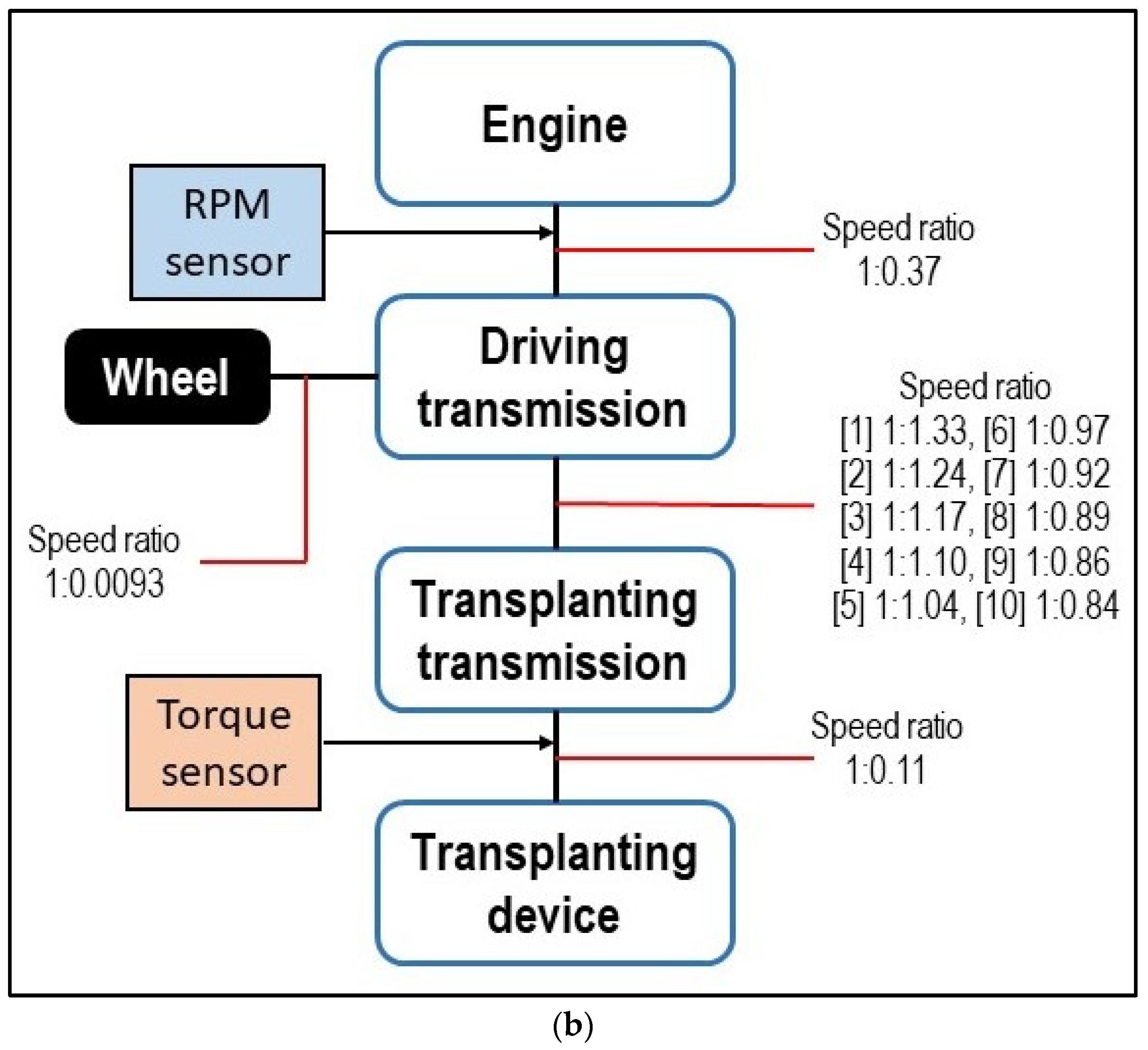
Figure 6 and
Figure 7, respectively, show the locations of the torque sensor and rpm sensor for the cam and four-bar-link types. A torque sensor was installed at the input shaft of the transplanting device, and the rpm sensor was attached to the transmission input shaft. The rotational speed of the input shaft of the transplanting device was derived from the rotational speed of the transmission input shaft and the reduction gear ratio between the two shafts (
Figure 8). The power consumed by the transplanting work was then calculated using Equation (1) [
23].
where
P is the power consumed by the transplanting work (kW),
T is the torque at the transplanting device input shaft (Nm), and
N is the rotational speed of the transplanting device input shaft (rpm).
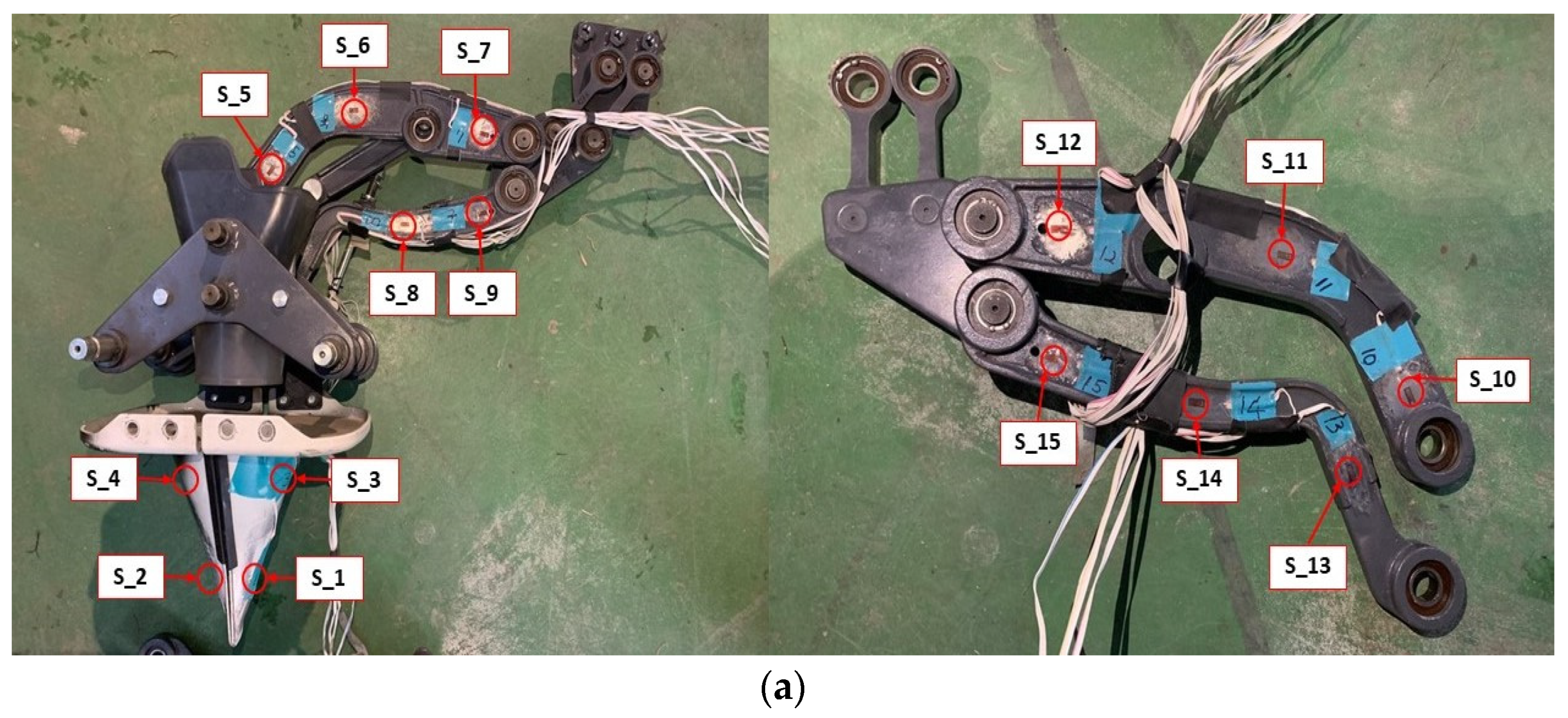
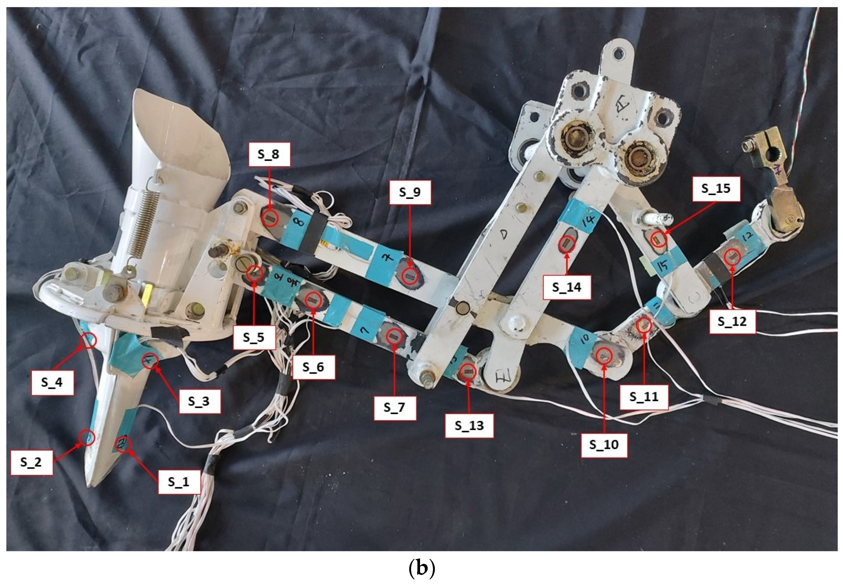
The strain sensors comprised 15 strain gauges attached to the main loading paths of the transplanting device to measure the stress during transplanting. Two types of strain gauges were used: a uniaxial strain gauge (KFGS-5-350-C1-11 L10M3R, KYOWA) to measure one-directional strain in the main loading direction, such as at linkages, and a triaxial strain gauge or rosette (KFGS-1-350-D17-11 L5M3S, KYOWA) to measure the strain in three directions in the main loading direction, such as at the surface of the transplanting hopper. The detailed attachment locations of the strain gauges are shown in
Figure 9 and
Table 3.
The measured strain data were converted into stress data for the safety analysis. Two types of safety analysis were conducted: static safety and dynamic safety (or fatigue life). For the static safety analysis, the static safety factor was calculated using the yield strength of the transplanting device material and the maximum stress that occurred during operation—see Equation (2). As for the maximum stresses, the maximum normal stress was used for uniaxial strain gauges, while the maximum von Mises stress was used for triaxial strain gauges. If the static safety factor is greater than 1.0, the design is considered statically safe. If the static safety factor is less than 1.0, this implies that the design is unsafe or that the part may fail.
where
SF is the static safety factor,
Sy is the yield strength of the transplanting device material (Pa), and
σmax is the maximum operational stress (Pa).
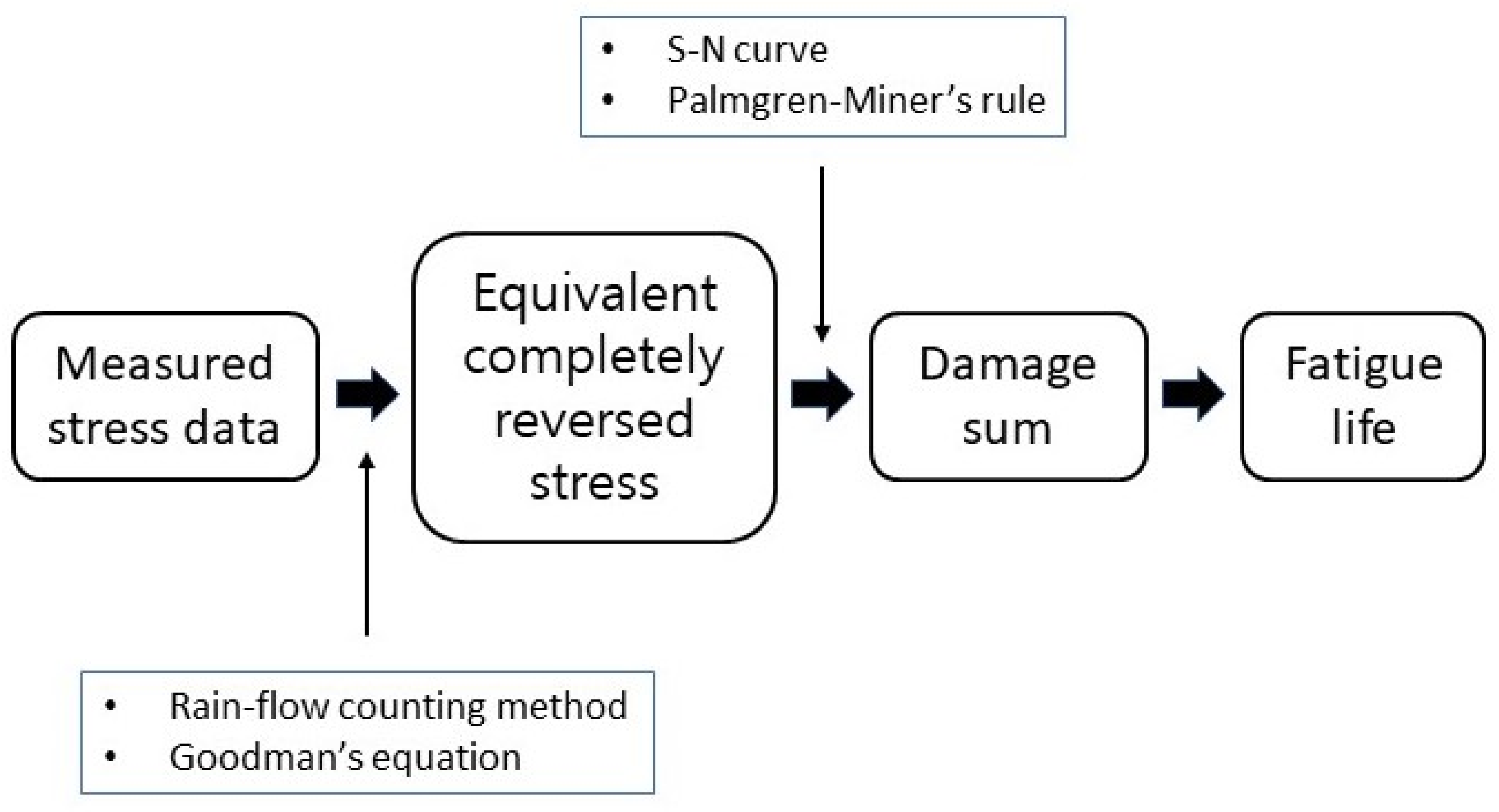
Fatigue life analysis is also required because the transplanting device is subjected to repeated cyclic loads when the vegetable transplanter is working.
Figure 10 shows the fatigue life analysis procedure.
The measured stress was converted into equivalent, completely reversed stresses and their corresponding loading cycles by applying the rain-flow counting method and Goodman’s equation [
33,
34]. The rain-flow counting method is used to obtain the loading cycles for each mean stress and stress amplitude from time-series stress data. Then mean stress and amplitude were used to derive the equivalent completely reversed stress using Goodman’s equation—see Equation (3). The actual applied loading cycle (
ni) can be derived from the rain-flow counting. The life cycles (
Ni) were determined from the S–N curve using the equivalent completely reversed stresses [
35]. The ratio between the actual applied loading cycles and the life cycles is called “partial damage”. The damage sum was calculated by summing the partial damages from all stresses that occurred during the operation using the Palmgren–Miner rule—see Equation (4) [
36]. Fatigue failure occurs when the damage sum reaches 1.0 [
37]. The damage sum and working time were used to calculate the fatigue life of the transplanting device, as shown in Equation (5). The 25.5 h of average annual usage time of vegetable transplanters was considered to determine the fatigue life in years [
11].
where
is the equivalent completely reversed stress (Pa),
is the ultimate strength (Pa),
is the stress amplitude (Pa),
is the mean stress (Pa),
D is the cumulative damage sum,
ni is the number of applied loading cycles for the equivalent completely reversed stress
i (cycles),
Ni is the life cycles for the equivalent completely reversed stress
i (cycles),
Lf is the fatigue life (s), and
t is the working time that generates the cumulative damage sum (s).
4. Conclusions
The torque, rotational speed, and strain were measured for cam and four-bar-link semi-automatic transplanting devices. The field test was conducted under various working conditions. The cam type has three engine speeds (1100, 1250, and 1550 rpm) and three planting distances (0.35, 0.40, and 0.45 m). The four-bar-link type has three engine speeds (1000, 1250, and 1500 rpm) and three planting distances (0.35, 0.41, and 0.45 m). The measured data were used to calculate and analyze the consumed power, static safety factor, and fatigue life of both types of transplanting devices.
The main results of this research are as follows:
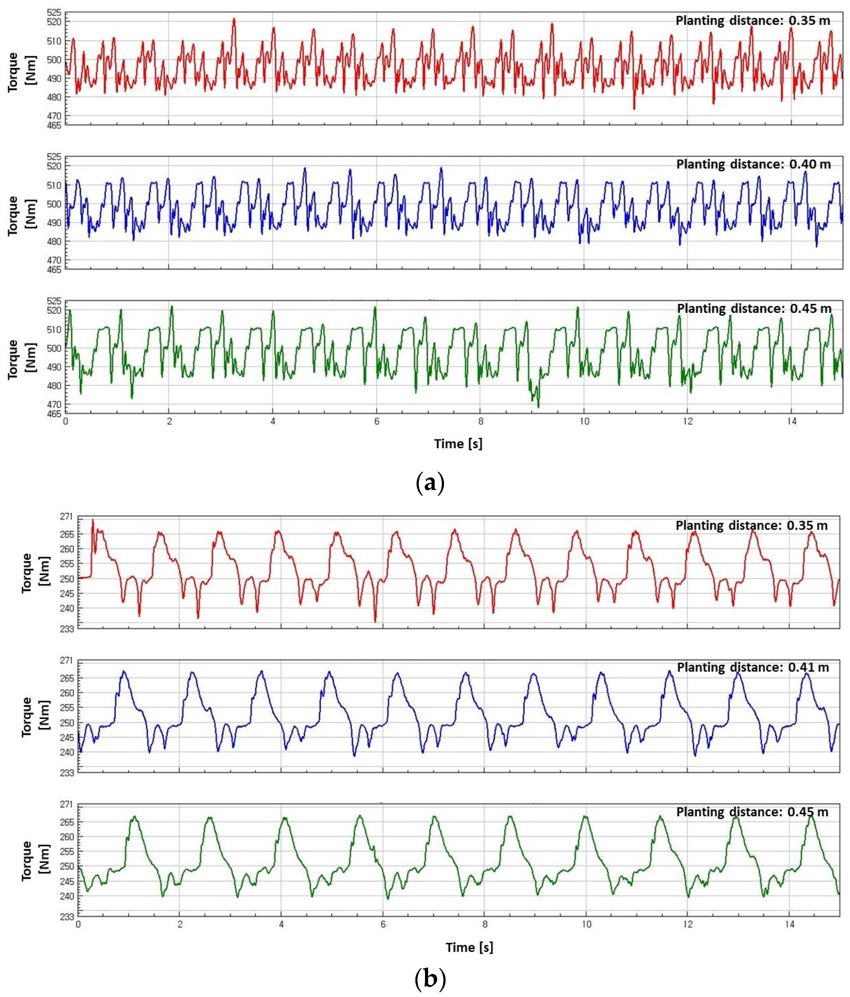
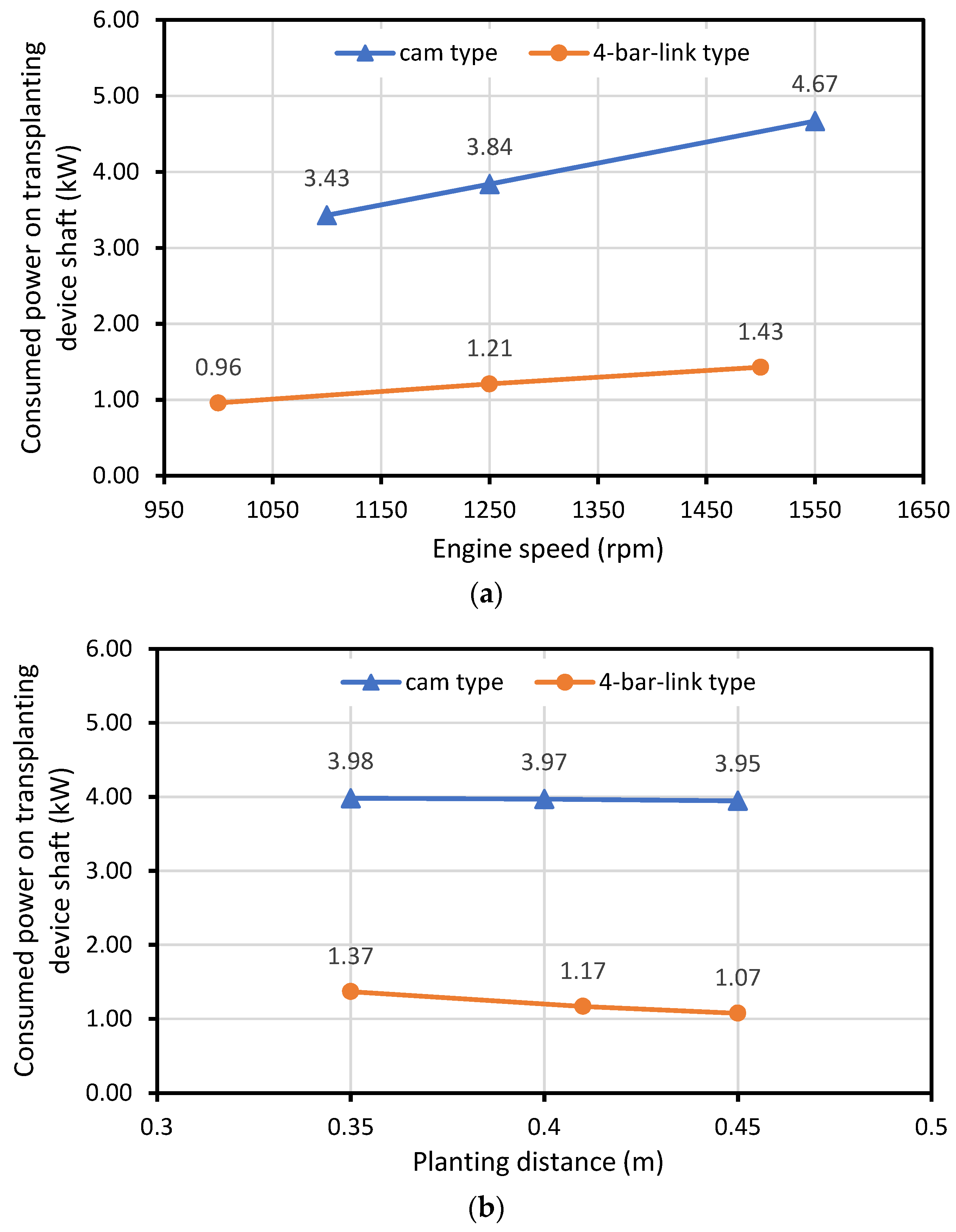
Under similar operating conditions, the cam type had a greater torque and consumed more power than the four-bar-link type owing to its rigid and heavier design. The range of the consumed power on the transplanting device input shaft of the cam type was 3.32–4.68 kW, while it was 0.84–1.66 kW for the four-bar-link type. The consumed power on the transplanting device input shaft increased when the engine speed increased and the planting distance decreased for both types.
The static safety factor was greater than 1.0 for both types at all measurement locations and under all working conditions. The minimum static safety factor for the cam type was 3.35 on the upper side of the transplanting hopper (S_4) at an engine speed of 1550 rpm and a planting distance of 0.35 m. For the four-bar-link type, the minimum static safety factor was 4.05 at one of the linkages (link D) at an engine speed of 1500 rpm and a planting distance of 0.41 m.
The minimum fatigue life for the cam type was 95,603 years at the upper side of the transplanting hopper (S_3) at an engine speed of 1550 rpm and a planting distance of 0.35 m. The minimum fatigue life for the four-bar-link type was 196,000 years at the same location with the minimum static safety factor (link D) at an engine speed of 1500 rpm and a planting distance of 0.41 m.
The rated work efficiencies of the cam and four-bar-link vegetable transplanters are similar. The cam type had a digital plant-spacing control device so that workers could work comfortably. However, considering the power consumption and price of the machine, the four-bar-link vegetable transplanter is highly economical.


