Article

Analysis of Operating Conditions for Vibration of a Self-Propelled Monorail Branch Chipper

1
College of Mechanical and Electronic Engineering, Shandong Agricultural University, Tai’an 271018, China
2
Provincial Key Laboratory of Horticultural Machinery and Equipment, Shandong Agricultural University, Tai’an 271018, China
*
Author to whom correspondence should be addressed.
Agriculture 2023, 13(1), 101; https://doi.org/10.3390/agriculture13010101
Submission received: 5 December 2022 / Revised: 23 December 2022 / Accepted: 23 December 2022 / Published: 29 December 2022
(This article belongs to the Section Agricultural Technology)

Abstract

:
Aimed at the problems of difficult treatment, unreasonable utilization and serious waste of fruit tree residue, combined with the terrain and planting characteristics of hilly orchards, a self-propelled monorail branch chipper was developed. It can realize long distances and large ranges of crushing operations and debris tiling in the garden. Because the monorail branch chipper adopts the half-empty suspension support method, the moving operations and discontinuous cutting of branches can lead to vibration failures or hazards. In response to this problem, modal analysis of a track system with different numbers of nodes by ANSYS software showed that an increase in the number of track sections decreases the natural frequency of each order under the condition of rigid fixation of the support rods, and weakness of vibration is especially seen in sections 1–4, but after a certain amount, the vibrational change tends to level off. The number of lateral rods should be increased for distal short rail branches of less than four sections to reduce operational and operational vibration. The vibration level test results of field multi-condition and multi-point grinding operations showed that the static vibration amplitude of the crusher is basically the same as that of the mobile state. The vibration amplitude of the chipper is significantly increased when in the states from no-load to grinding operation, and the maximum vibration occurs in the left and right direction of the transverse rail, which provides a theoretical basis and optimization direction for further optimization of the single-track branch chipper operational stability problem.

1. Introduction

For large orchard area and high yield annually [1,2], branch pruning is an important part of fruit tree management, and the pruning volume is large [3], but the utilization rate of pruned branches is low and they are usually used as firewood [4,5,6,7]. As a rich biomass resource, fruit tree residues can be used for mushroom substrates, sheet and paper manufacturing, biomass gasification and liquefaction, solid fuel forming, etc. Wood chips can help improve soil if used as mulch, can help control moisture, soil temperature, weeds, and provide organic matter. Another important benefit from wood chip mulch is the suppression of weeds. Limiting weed presence reduces competition for water and nutrients, which supports plant growth [8]. Using this method to utilize wood chips can reduce transportation costs, reduce labor intensity, and reduce the use of chemical fertilizers. In order to promote the green development of the fruit industry, it is the optimal way to use [9].
As is well-known, the hilly region is an important production base of the fruit industry, subject to terrain, planting patterns, and other factors, fruit tree management mechanization level is low, and manual work is intensive, low efficiency, and high cost [2]. Scattered fruit tree planting due to topographical constraints, if collected and transported to the bottom of the mountain for chipping, will increase the collection labor intensity, increase the difficulty of transportation, and reduce chipping and return efficiency. At the same time, once again, limited by the terrain, it is difficult for the existing chipper to enter the orchard, and poor movement in the garden led to a significant reduction in chipping efficiency. The treatment of fruit tree residues in hilly mountainous areas is more difficult and the utilization rate is lower, while no systematic research has been reported on the treatment of organic fertilization by in situ crushing [10].
A lot of research has been done on chippers, for example, the kinematic analysis of the cutting process with flying cutters to facilitate the initial selection of the tool roll size [11]; risk assessment of safety posture during manual feeding with a goal to reduce safety risks [12]; energy consumption tests of different types of chippers, which point out that chippers should have independent engines [13]; and flying knife wear research, which shows that the greater the amount of wear, the worse the crushing quality [14]. In addition, there are studies on the efficiency of wood chip transportation, optimization of screen structure, and cutting speed, by the Plackett–Burman test [15,16]. Few mobile chippers are used inside orchards, limited by topography and other constraints, and those that can be used in hilly orchards are even fewer. Wang Qiang optimized the control system of the orchard chipper, designed with a branch collection device for easy branch collection [17]; Wang designed the chipper with a multi-blade drum structure, where the movement method is wheeled and the pass ability is poor [18]. Therefore, the current hilly orchard chipper used is mostly crawler type, with better pass ability than the wheeled type in the same height block field [19,20]. The self-propelled monorail transporters are the main transport equipment in hilly mountain orchards in China at present. Zhang Yanlin, Song Yuepeng, and other research teams have carried out research work on the design and manufacture, performance optimization and demonstration, and promotion of self-propelled monorail transporters, respectively [21,22]. Based on the monorail transport system, Song Yuepeng et al. developed a branch chipper suitable for hilly mountain orchards. However, the machinery crushing operation vibration is violent, rail shaking is serious, and there exists a large noise. The equipment adopts a free feeding method, the branches jump violently under the vibration and even pop out of the feeding channel to hurt people. In addition, manual feeding efficiency is low, and the fix point feeding needs to be pre-collected by certain points. However, the problem that limits the stable use of the machine and requires further improvement is still the vibration problem in the first place. Vibration of the chipper affects the quality of slicing and reduces the service life, and self-propelled monorail branch chipper vibration is too large, thus it will reduce the strength of the rail installation. Damage to the track, or even dumping, causes mechanical rollover on rails.
Based on this, the paper adopted computer numerical simulation technology to carried out modal analysis and vibration characteristics research on different section number track systems, and, at the same time, carried out vibration level testing of actual crushing operations in multiple working conditions and points in the field. The research results provide a theoretical basis and optimization direction for further optimizing the operational stability of self-propelled single-track branch chippers, and further enhance the utilization level of fruit tree residues and biomass resources in the hilly mountain orchards.

2. Overall Structure and Working Principle

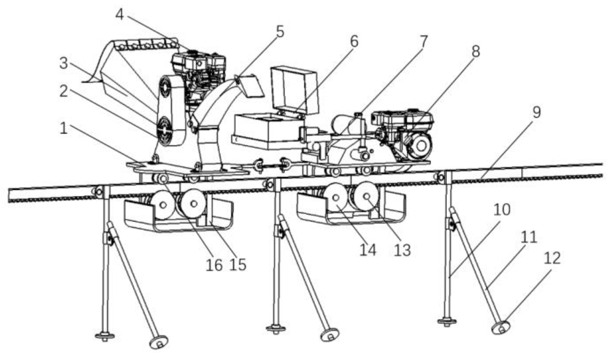
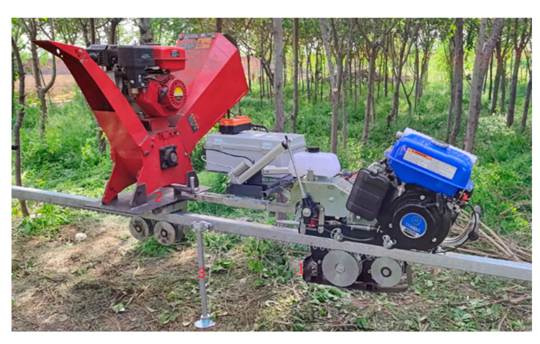
2.1. Overall Structure

Most of the hilly mountain orchard machinery is of crawler type, wheel type, and a single line of track, as the orchard management machinery walking relying on the advantages of the mechanism is obvious. Single-track traction is smaller than wheeled lateral size, puts less pressure on the ground, and is less affected by soft road surface, but has strong climbing ability, has stronger adaptability than the crawler type, is less affected by potholes, has a smaller footprint than double-track traction, and has a more flexible arrangement.
In this paper, a single-track self-propelled branch chipper for hilly orchards is designed based on the single-track traction method. The overall structure is shown in Figure 1.

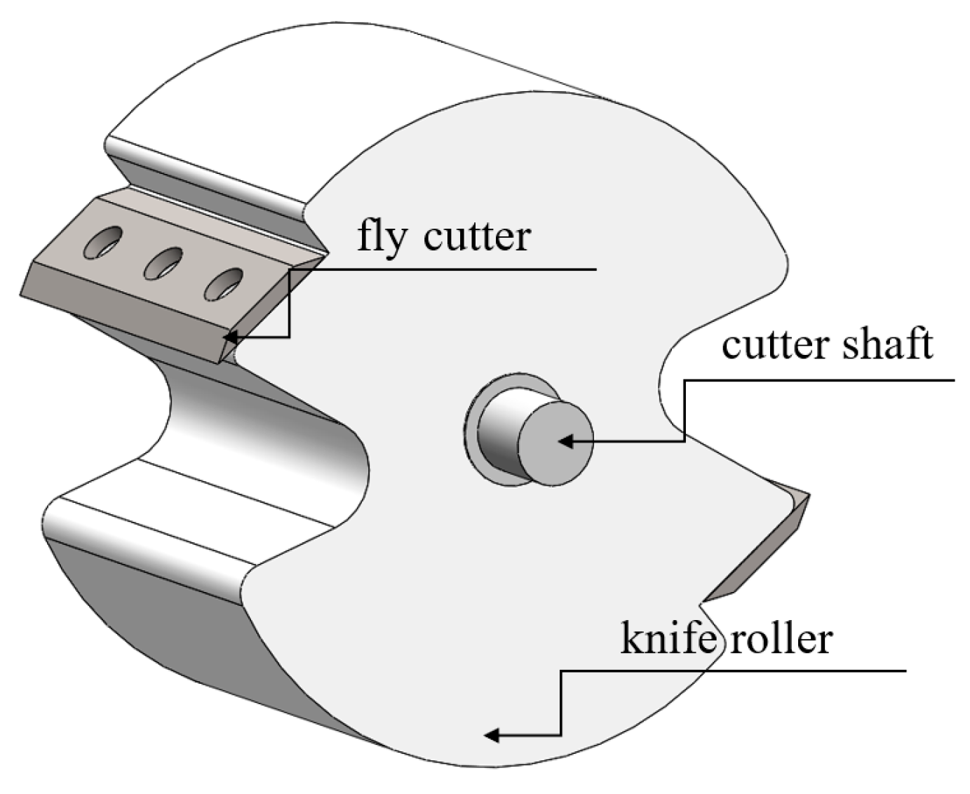
2.2. Working Principle

The randomization of fruit tree branch pruning leads to the haphazard distribution of residual branches, which are difficult to collect; in addition, the low density of branches and the multiplicity of residual fine branches leads to the difficulty of transportation and storage. Self-propelled single-track branch chippers adopt manual feeding with static fixed-point crushing, and mobile crushing as two modes of operation, with a unique branch and shear and shredding operations quickly crushed.
This monorail self-propelled branch chipper adopts dual gasoline engines as the power source, which are used for the traction mechanism and branch crushing mechanism. The traction mechanism and the crushing mechanism are reliably connected to the cross rail through the engagement mechanism, the cross rail is steadily erected at 30 cm from the ground through the main and secondary branches, and the crushing mechanism relies on the traction mechanism to realize the shuttle operation between the gardens, which is convenient and efficient with the remote control system.
Machinery and equipment for internal operations in hilly orchards require small size for easy moving between fruit trees, thus adopt a drum type cutter. A total of two flying knives with symmetrical distribution of 180 °. According to the requirements of fruit tree branch pruning, the diameter of the cut branch is mostly below 40mm, and the operation object of the chipper is the branch within 80mm in diameter. The main technical performance parameters of the single-track self-propelled branch chipper are shown in Table 1.

3. Modal Analysis of Rail Systems

3.1. Principles of Modal Analysis

The phenomenon of violent vibration is common during the operation of the shredder, and its vibration comes from many sources, most notably from the high-speed rotating impact of the cutting mechanism when crushing the branches. Due to the structural form and discontinuous and uneven cutting, shredder vibration is a real problem that can only be optimized, but is unavoidable. The single-track self-propelled branch chipper, due to suspension on top of the cross rail, the crushing mechanism and traction mechanism gasoline engine, knife roller rotation, and discontinuous cutting movement generated by the vibration, will be attached to the track system, causing adverse effects on track safety. The simulation software ANSYS Workbench was used to perform modal analysis of the rail system to provide a basis for subsequent design to avoid resonance and reduce vibration amplitude.
Modal analysis is an effective method to study structural vibration characteristics and is the basis of dynamic analysis. The universal equation for the dynamics of the object is known from classical mechanics as [23]:
M x ¨ + C x ˙ + K x = { F t }
In the equation:
  • M ——quality matrix;
  • C ——damping matrix;
  • K ——stiffness matrix;
  • { F t }——force vector;
  • x ——displacement vector;
  • x ˙ ——speed vector;
  • x ¨ ——acceleration vector.
The physical quantity of time can be neglected in the actual analysis process, and the universal equation of dynamics is simplified as:
K x = F
Doing modal analysis on the statics is closer to the actual results than not considering pre-stressing modal analysis [24]. Based on the results of the static analysis, the vibration pattern and angular frequency can be calculated by the following equation, ignoring the small damping coefficient [25]:
K ω i 2 M { φ i } = 0
From the static analysis Equations (2) and (3), the modal analysis is calculated as:
K + S ω i 2 M { φ i } = 0

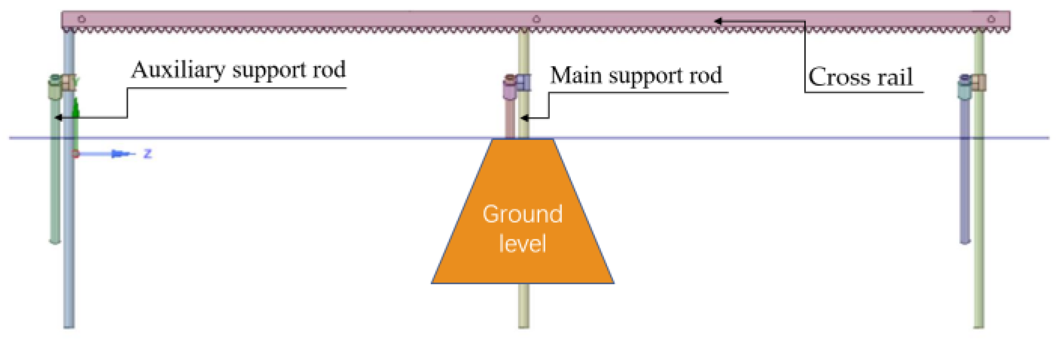
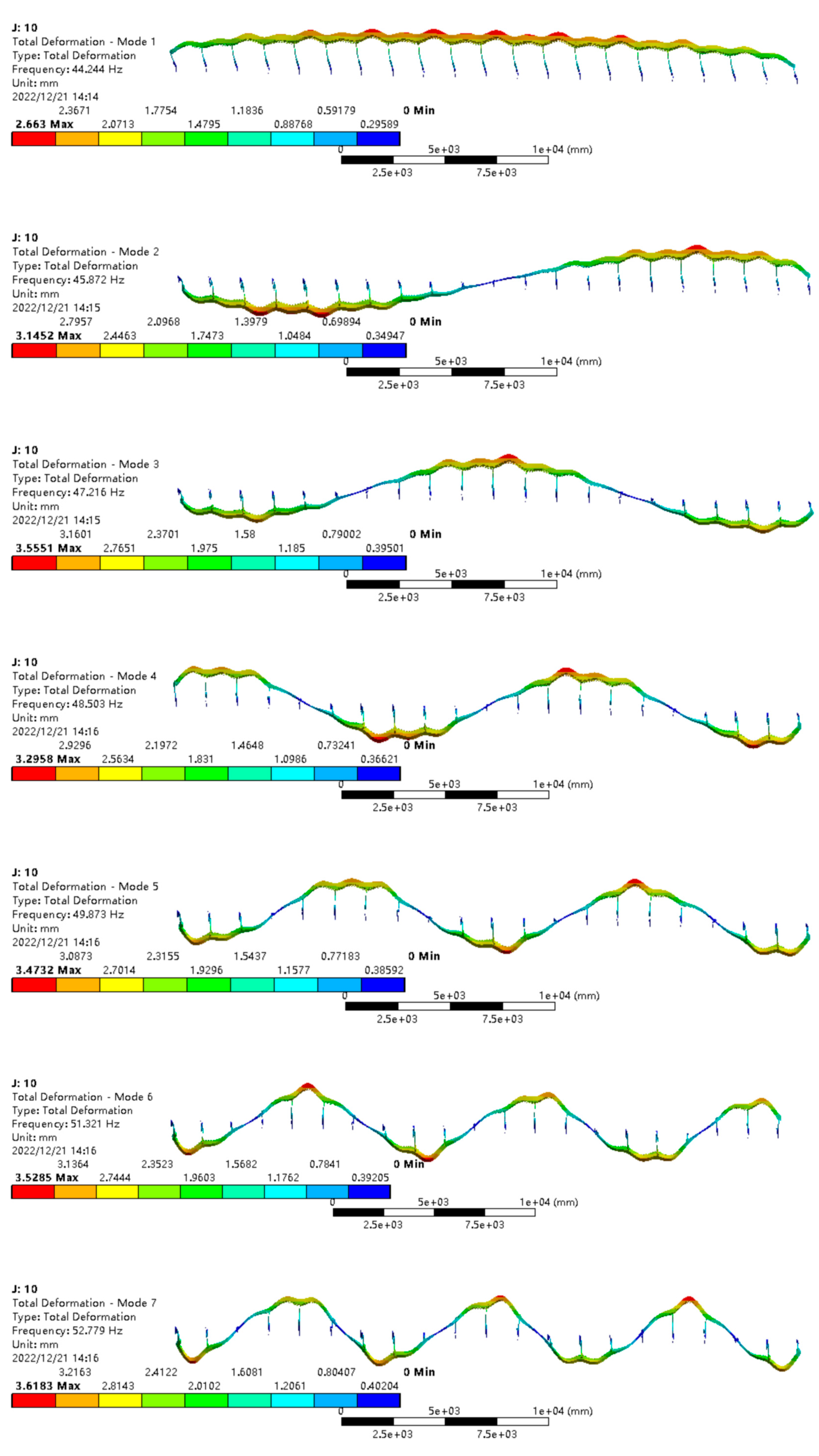
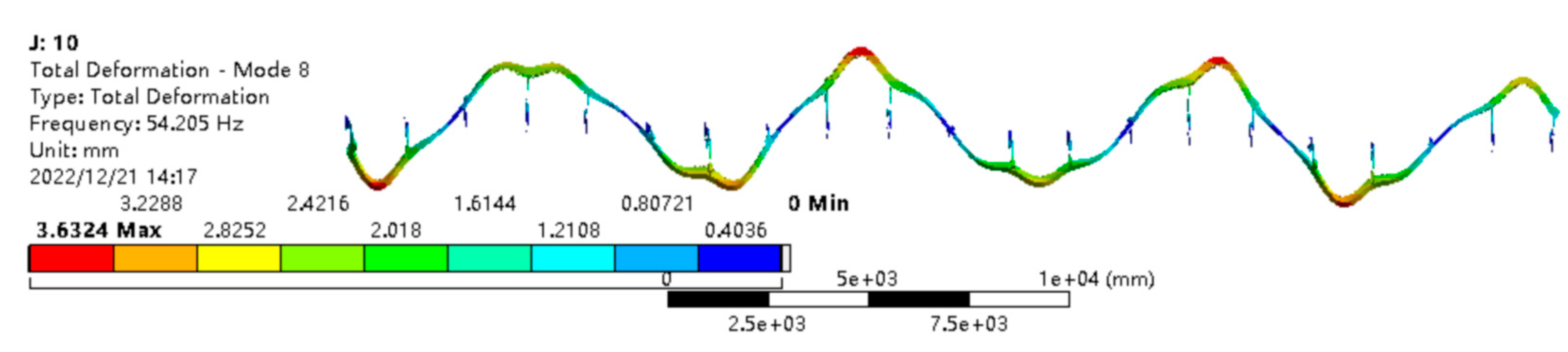
3.2. Rail System Modal Analysis

The track system mainly consists of cross rails and support members, which provided stable support force for the components on it and are the basis for the shuttle operation of this shredder. The main support rod and auxiliary support rod in the actual arrangement of about 400–700 mm are buried in the ground, the cross rail will be supported at a height of 300–400 mm from the ground, the length of the main support rod is 1000 mm, and the length of the auxiliary support rod is 800 mm. The cross rail and support member models were simplified and imported into Workbench software, and the support bars below the ground line were subjected to fixed constraints to simulate the actual erection conditions. The simplified structure and Workbench software import model are shown in Figure 2, and the modal analysis parameters are set as shown in Table 2.
The track system of the monorail is easy to lay, adaptable, and can be built flexibly according to the characteristics of the terrain to realize the curves into straight and steep into slow. In China presently, the hilly mountain orchards are mostly small fields, terraces grouped together, resulting in large gardens, whole garden less, and fruit tree planting is not standardized, and distribution is scattered, so the track system uses distal short branch rail. Hu Yongguang of Jiangsu University designed a variable track device to dynamically connect the trunk and each remote side track with a mobile single or double section track to meet the transportation needs of each field and reduce track construction costs [26]. The number of sections of a single-track system, that is, the length of each track, varies due to the variable track laying. The modal analysis is carried out for the different building forms of the track, namely the different number of sections, in order to investigate the regular relationship between the number of sections and the natural frequency of the track, to reduce the amount of calculation, and to provide guidance for the subsequent design, test, and practical application.
As shown in Figure 3 and Figure 4, it is founded that the inherent frequency of each order decreases as the number of orbital sections increases, the decrease between adjacent sections decreases gradually with the increase of the number of orbital sections, and the larger the order, the faster the decay. Among them, in the 1–4 sections of the track, each order of the natural frequency reduction is obvious; between 1 section and 2 sections, there is an eighth-order vibration reduction of up to 43.5% and a first-order vibration reduction of 5.5%. The reduction of the natural frequency of each order of 4–10 sections of the track is less than 5%, the reduction of the vibration pattern of the first eight orders between 9 and 10 sections are less than 2%, and the first five orders are less than 1%. The corresponding mass normalized vibration pattern is consistent with the overall change of the first eight orders of natural frequency, where sections 1–3 are the obvious change area, sections 3–8 are the undulating overall decline area with small amplitude change range, sections 9–10 are the stable area, and the vibration pattern is basically unchanged. Therefore, the modal analysis of the track after 10 sections is not carried out anymore, and the natural frequency and vibration pattern of 10 sections of track are used as the basis for design and build.
The first-order vibration of the rail system cross rail and the support bar is oscillating left and right along the rail, and the maximum oscillation is stretching outward along the support bar; the second-order vibration pattern is centered on the cross section at the midpoint of the track and twists left and right along the track; the third-order vibration pattern is shown as three equal up and down jumps along the front and back of the support rod, in which the two equal parts are in the same direction and the middle equal parts are in the opposite direction; the fourth-order oscillation pattern is shown as swinging left and right along the track in four equal parts, in which the adjacent equal parts swing in opposite directions while the track is turned to the outside; the fifth-order to eighth-order oscillation patterns are basically the same, which are shown as swinging left and right along the track in 5–8 equal parts. The results of the first eighth-order modal analysis of the 10-section track are shown in Figure 5.

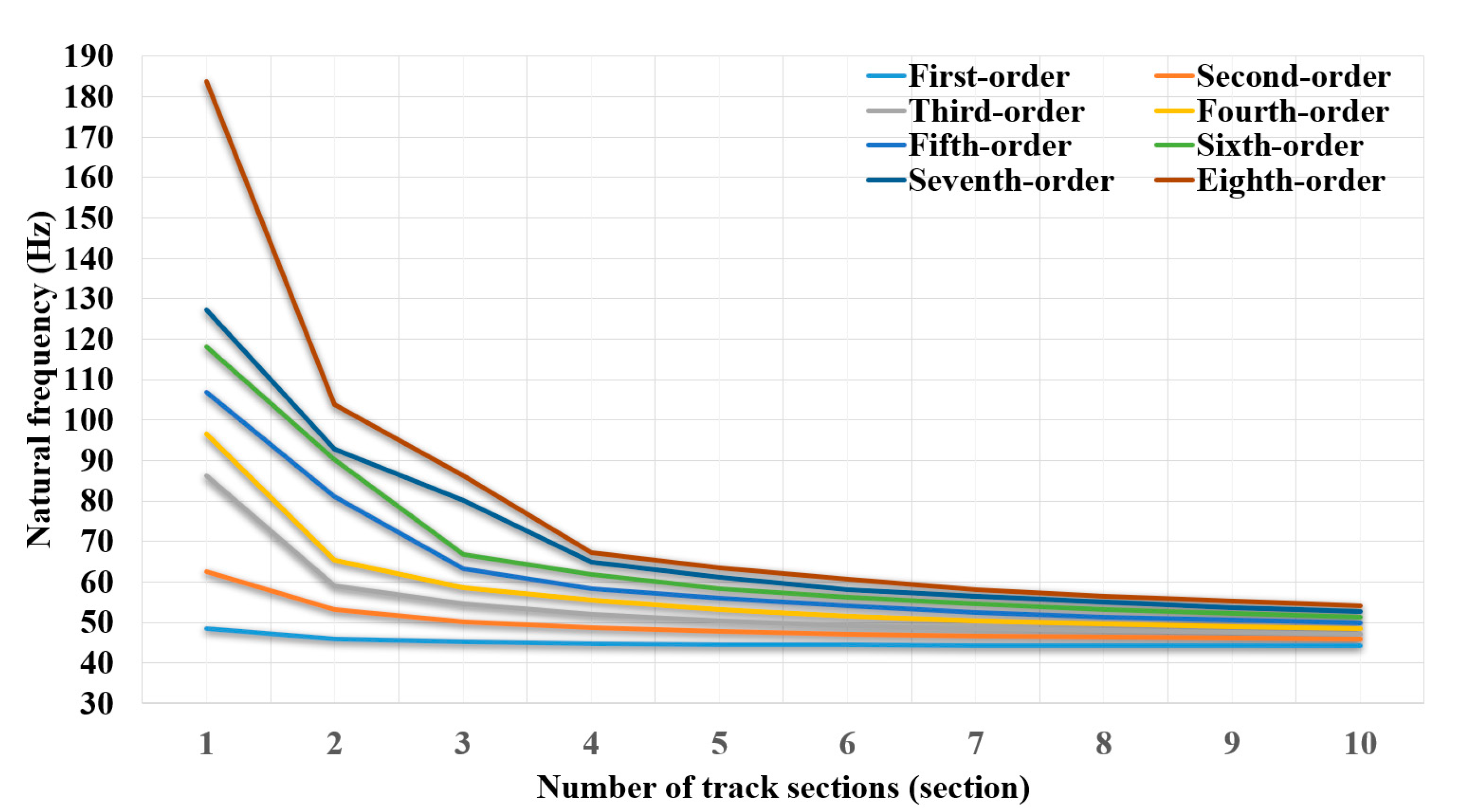
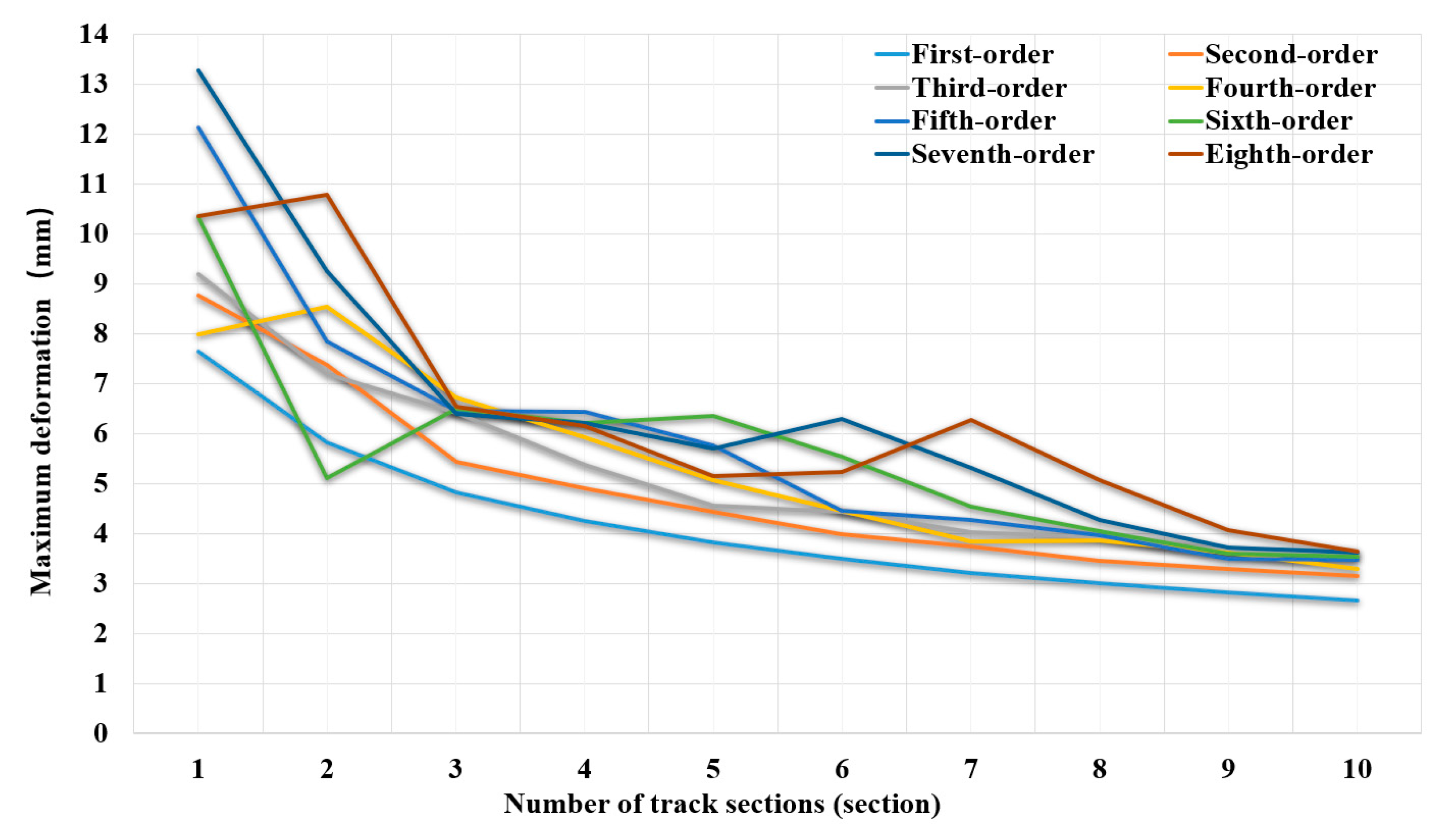
3.3. Analysis of the Results

The single-track self-propelled branch chipper is designed with dual power sources and is a multi-degree-of-freedom elastic system, which is prone to deformation and vibration under external excitation, and also resonates when the external excitation frequency is close to the natural frequency of the member itself, of which the gasoline engine is the main source [27]. Gasoline engine combustion outputs periodic pulse torque, resulting in gasoline engine reaction torque fluctuations; the fluctuations are called combustion excitation, and the frequency calculation equation is [28]:
f 1 = 2 n i 60 c
In the equation:
  • n ——speed of gasoline engine, r/min;
  • i ——gasoline engine’s number of cylinders;
  • c ——number of strokes of gasoline engine.
The inertial excitation of the gasoline engine caused by the mass imbalance of the rotary and reciprocating motion combined with the excitation frequency of the moment of inertia is calculated as:
f 2 = Q n 60
In the equation, Q is the unbalanced scale factor with first-order Q = 2 and second-order Q = 3.
The single-track self-propelled branch chipper adopts a drum structure and consists of a knife roller, flying knife and fixed knife, in which the flying knife and knife roller are cemented together for cutting movement and cooperate with the fixed knife to complete the branch crushing operation. The designed knife roller speed is 2300 r/min and the flying knife wedge angle is 32° [29,30]. The structure of the knife roll is shown in Figure 6.
The knife roller frequency is related to the rotational speed, and its calculation formula is [31]:
f 3 = n 60
The chipper cutting mechanism has two flying knives, which are arranged symmetrically at 180° to reduce unbalanced vibration disturbance. During the crushing operation, the cutting action of the flying knife on the branch is discontinuous, and, therefore, the frequency of impact repetition is:
f 4 = n r 60
In the equation, r —the number of flying knives.
The gasoline engine of the traction mechanism is a 4-cylinder 4-stroke with a speed of 1800 r/min, and the gasoline engine of the crushing mechanism is a single-cylinder 4-stroke with a speed of 3600 r/min, the knife roller speed is 2300r/min.
From the above formula, the traction mechanism combustion excitation frequency is 60 Hz, the first-order inertia excitation frequency is 60 Hz, the second-order is 120 Hz, the combustion excitation frequency of the crushing mechanism is 30Hz, the first-order inertia excitation frequency is 60Hz, the second-order is 120Hz, the knife roller interference frequency is 38Hz, and the impact repetition frequency is 77Hz. Combined with the results of the first eight orders of the rail system modal analysis, it can be seen that the natural frequency of each order of the rail system does not overlap with the external excitation interference frequency, which proved that the single-track self-propelled branch chipper is in a low-frequency stable operation. In addition, from the modal analysis results, it can be seen that the higher the number of track sections built, i.e., the longer the track system, the higher its stability, but after more than 10 meters it basically tends to be the same; for the distal short track branches less than four sections, the number of lateral branches should be increased to reduce the swing amplitude.

4. Vibration Test of the Chipper under Different Working Conditions

In order to further determine the vibration of the single-track self-propelled branch chipper, based on the results of the modal analysis, a 10-section track system was built to support the inter-garden test prototype, with the aim of setting up an operational vibration test system and to conduct vibration test research on the main components of the chipper, i.e., the cutting mechanism, at multiple points under multiple operating conditions such as empty running, stationary crushing operations, and inter-garden shuttle crushing operations, to gain a comprehensive understanding of the operating vibration of the chipper, to investigate the impact of different component vibration frequencies and amplitudes on the crushing quality, and to provide technical reference for subsequent optimization and rational selection of operating modes.
To ensure a simple and compact structure and access to non-standard dense orchards, the crushing mechanism selects a drum cutter. Because its chopping method is chop-can type, the vibration is violent, causes structural damage, and reduces service life [32]. Chou Shucheng tested the vibration of the orchard monorail truck at different operation speeds, and the results showed that the higher the speed, the larger the vibration [28]. Ma Hongyue explored the effect on vibration conditions of a drum chipper with different speeds and different feeds, and it is proposed that it works in a low-frequency steady state [33]. In this paper, they compared the characteristics of the two and controlled the speed for a fixed value on the transport vehicle. This test session was divided into static fixed point no-load, static fix point shredding, mobile no-load, and mobile shredding. Test points were located at the rear end of the tractor travel mechanism protection frame, the surface of the crushing mechanism pallets, and the middle of the main support rod. The test schematic is shown in Figure 7.

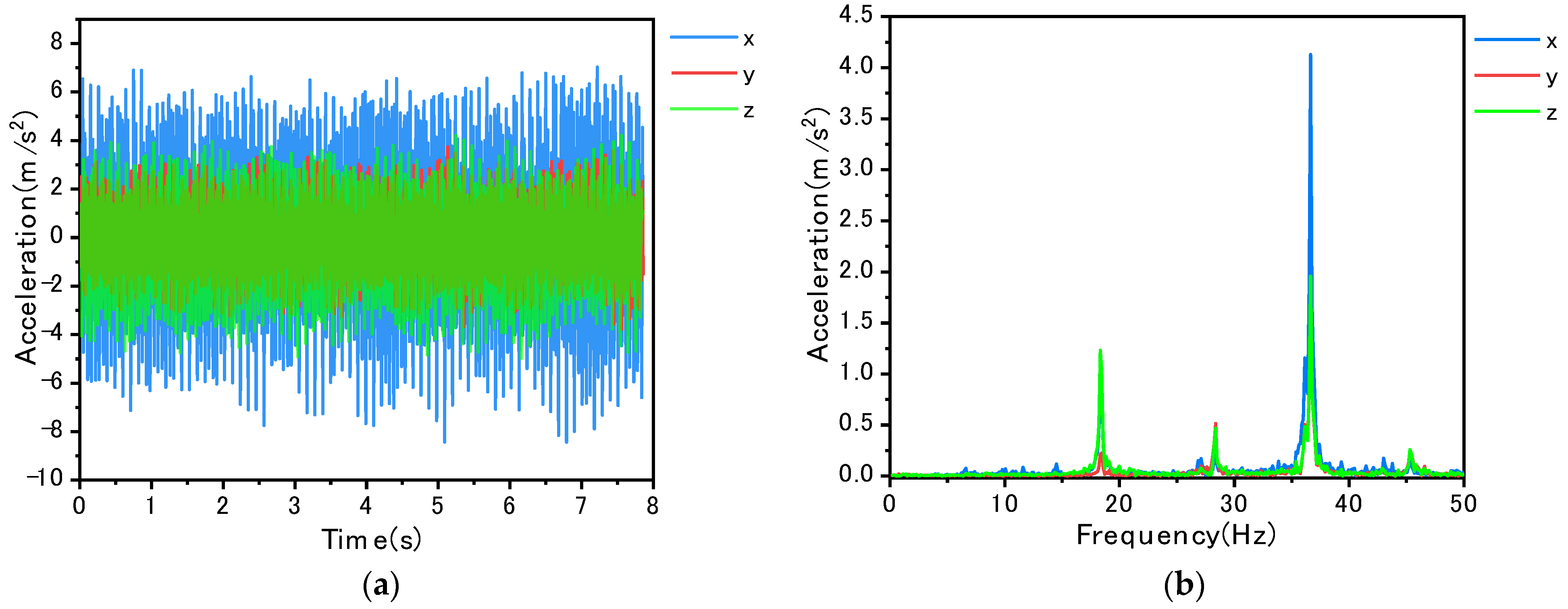
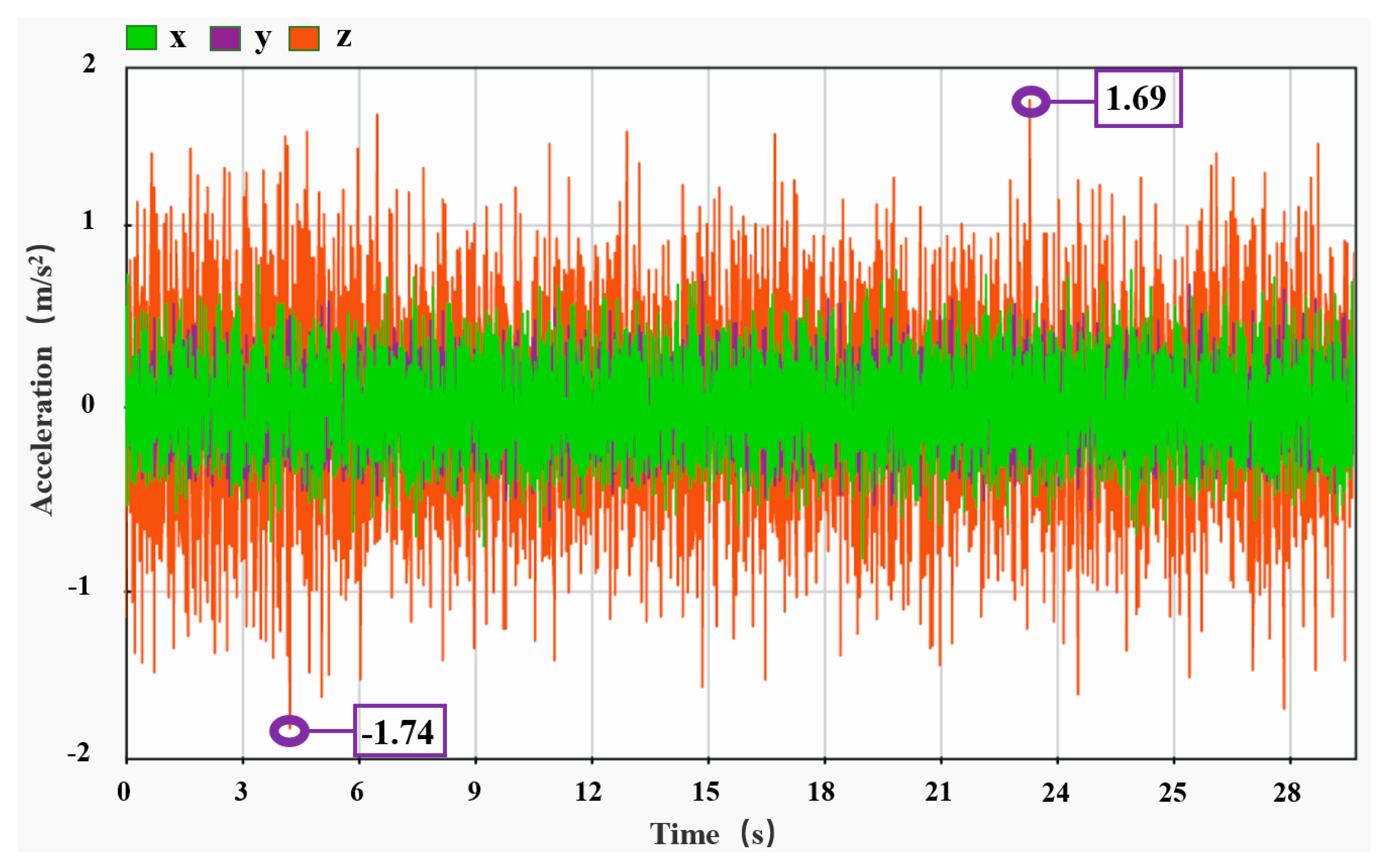
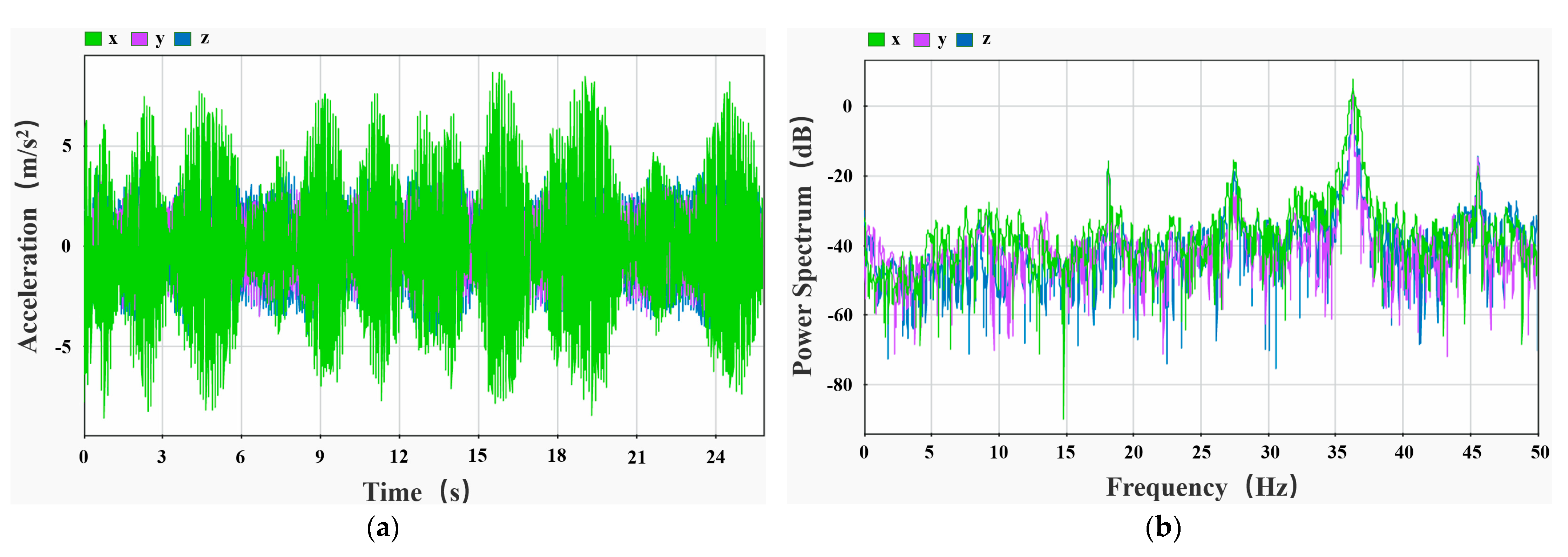
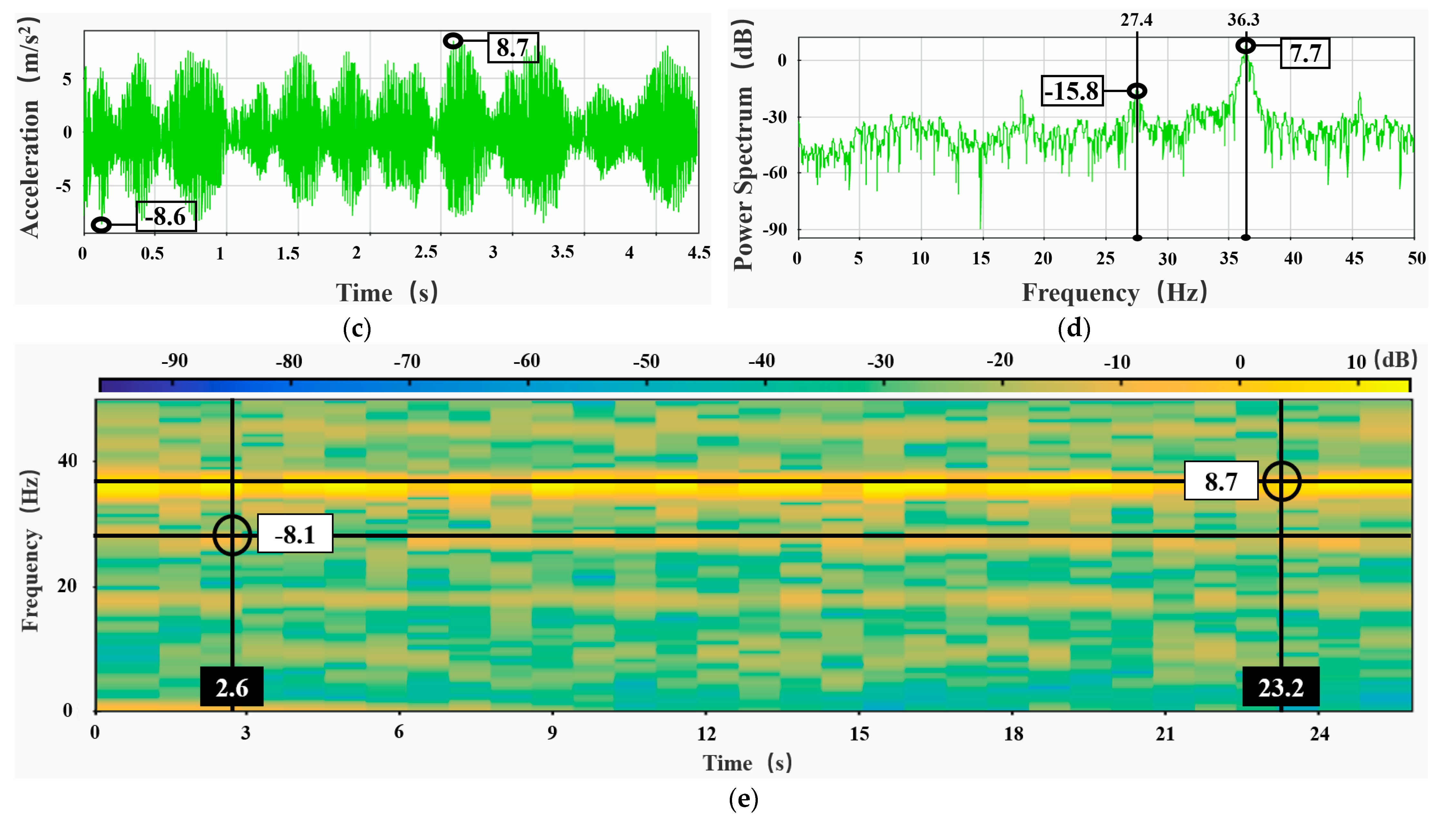
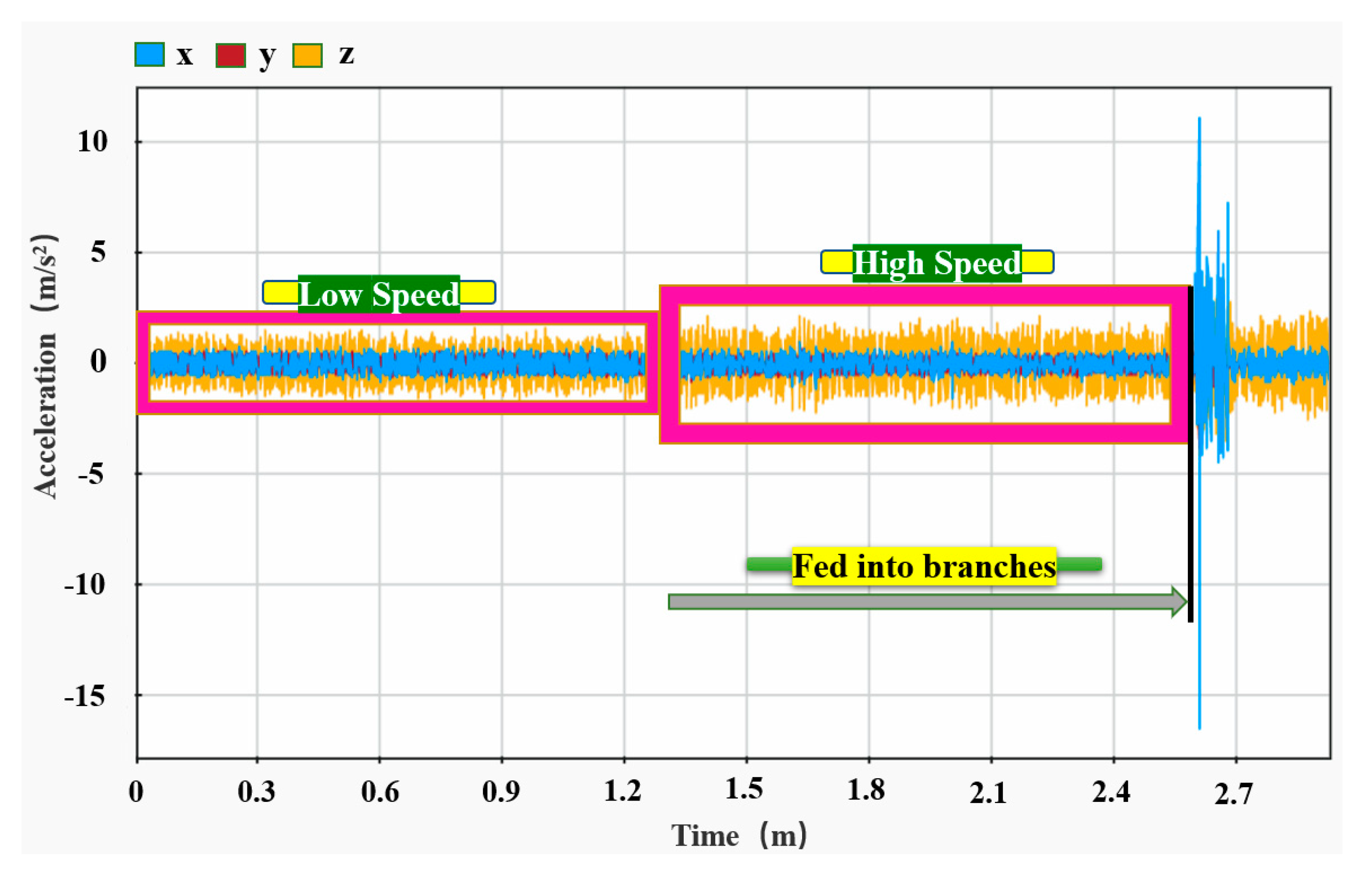
4.1. Vibration Test at No-Load

As shown in Figure 8a, the maximum amplitude of vibration in the x-direction of the tractor travel protection frame when the chipper is at rest and unloaded is 8.4 m/s2, and the maximum relative amplitude is 15.5 m/s2 in the left and right direction; the z-direction vibration amplitude is the second highest, with a maximum value of 5.0 m/s2, and the maximum relative amplitude is 9.2 m/s2 in the upward and downward direction; the y-direction vibration amplitude is the smallest, with a maximum value of 3.8 m/s2, and the maximum relative amplitude is 7.5 m/s2 in the forward and backward directions. As shown in Figure 8b, the maximum vibration amplitude in this condition occurs at 36.6 Hz, with 4.1 m/s2 in x-direction, 1.8 m/s2 in y-direction and 2.0 m/s2 in z-direction.
As shown in Figure 9a, the maximum amplitude of vibration in the x-direction of the tractor travel protection frame when the chipper is moving unloaded is 7.9 m/s2, and the maximum relative amplitude is 15.3 m/s2 in the left and right direction; the z-direction vibration amplitude is the second highest, with a maximum value of 3.6 m/s2, and the maximum relative amplitude is 7.1 m/s2 in the upward and downward direction; the y-direction vibration amplitude is the smallest, with a maximum value of 1.8 m/s2, and the maximum relative amplitude is 3.6 m/s2 in the forward and backward directions. As shown in Figure 9b, the maximum vibration amplitude in this condition occurs at 36.2 Hz, with 5.1 m/s2 in x-direction, 0.8 m/s2 in y-direction, and 2.4 m/s2 in z-direction. Compared with the stationary condition, the maximum vibration amplitude in the time domain and the maximum vibration amplitude in the frequency domain is slightly decreased in frequency; the reason for this is that when the chipper moves, the external environment generates random vibration to the original regular vibration caused by certain interference, and in the complex interaction between the two influences, the external interference plays a weak role [34].
As shown in Figure 10a–d, the maximum amplitude of vibration in the z-direction (front and rear) of the chipper at standstill no-load is 6.6 m/s2, and the relative maximum amplitude is 12.8 m/s2 in the forward and backward direction, with two peaks at 30.7 Hz and 46.7 Hz. The maximum vibration direction of the walking protection frame in the aforementioned test is in the x-direction, while the pallet is in the z-direction. The vibration amplitude in x-direction is the smallest, much smaller than the z-direction, and its value is 2.5 m/s2, and the relative maximum amplitude in the left and right is 3.7 m/s2, which is determined by the form of the components. The walking protection frame is fixed by the bottom plate from the bottom z-direction, and the chipper is fixed by bolts in the x-direction of the pallet, which limits the fluctuation range to a certain extent, thus the vibration amplitude is different, i.e., the vibration effect is different if the fixing method is different [35].
As shown in Figure 11, the support rod vibrates less due to the ground restriction. The maximum amplitude of vibration in the z-direction has a value of 1.74 m/s2 and a relative maximum amplitude of 3.34 m/s2 in the forward and backward direction; the y-direction vibration amplitude is small and uniform, with values between 0.3 and 0.6 m/s2, and the x-direction and y-direction vibration amplitudes are basically the same. As can be seen from Figure 7, the test point is the center of the exposed ground part of the support rod, which is restrained by the ground, and the closer the test point is to the ground, the smaller the vibration amplitude.
As shown in Figure 12, the effect of the moving operation of the single-track self-propelled branch chipper on the vibration amplitude of the support rod is great. When the chipper is far away from the test point, the z-direction vibration amplitude is the largest, with values fluctuating between 1 and 3 m/s2, while the y-directional and x-directional vibration amplitudes are smaller; when the chipper crosses the test point, the x-directional vibration increases instantly, with a maximum amplitude of 9.1 m/s2 and a relative maximum amplitude of 16.5 m/s2 in the left and right direction, while the y-direction and z-direction vibration amplitudes remain basically unchanged. Affected by the traction mechanism gearbox, the crushing mechanism knife roller rotation and gasoline engine excitation frequency are different, the chipper in the approach and drive away from the test point show different vibration patterns, but the vibration amplitude is basically the same.
The self-propelled monorail branch chipper idle vibration test results show that the maximum vibration occurs in the left and right direction of the track support rods, with a maximum value of 9.1m/s2; the next is the left and right direction of the walking protection frame, with a maximum value of 8.4m/s2; the chipper pallet vibration is the smallest, its maximum occurs for the front and rear direction, with a maximum value of 6.6m/s2. The orchard monorail truck vibration test results show that its no-load maximum vibration is 5.2m/s2 and full load maximum vibration is 16.3m/s2 [28]. The same as the no-load condition, the maximum vibration amplitude of the self-propelled monorail branch chipper is 1.75 times that of the orchard monorail truck. However, the self-propelled monorail branch chipper is equivalent to 0.33 times the full load condition; from this point of view, the vibration characteristics are basically the same between the two. When the chipper is unloaded, the maximum vibration is largely the same as the self-propelled monorail branch chipper [32]. From this, we can conclude that in the self-propelled monorail branch chipper, when unloaded, the track system did not increase the vibration level of the chipper and the chipper did not increase the vibration level of the track system.

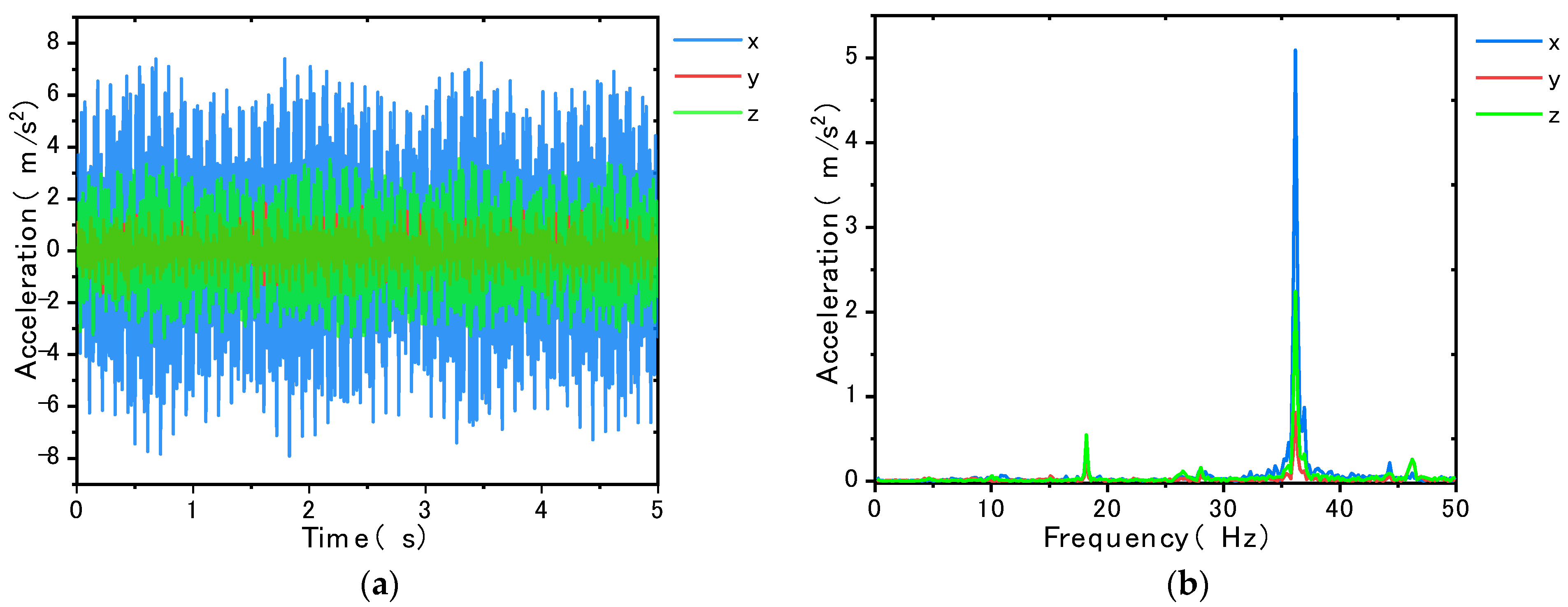
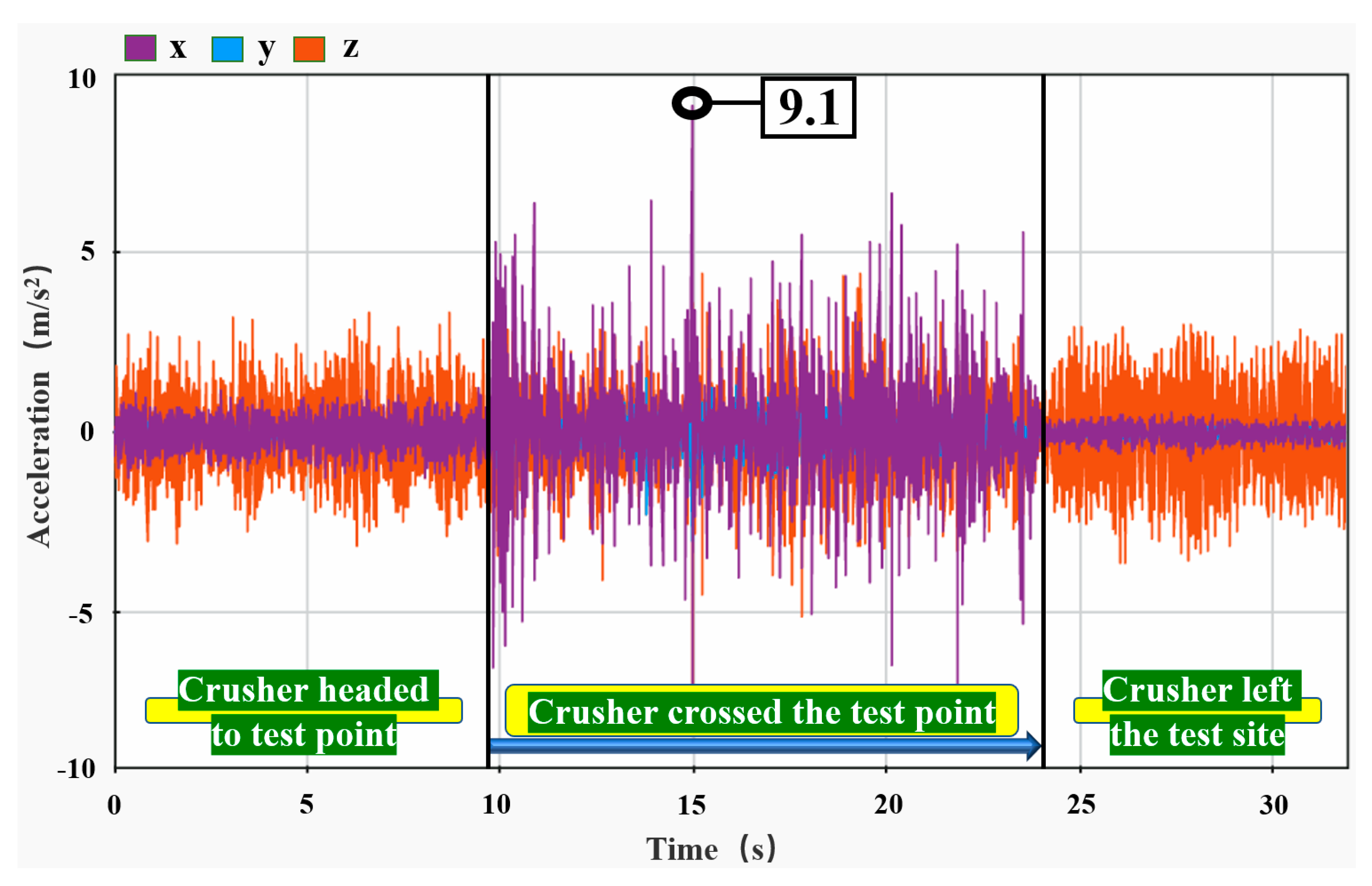
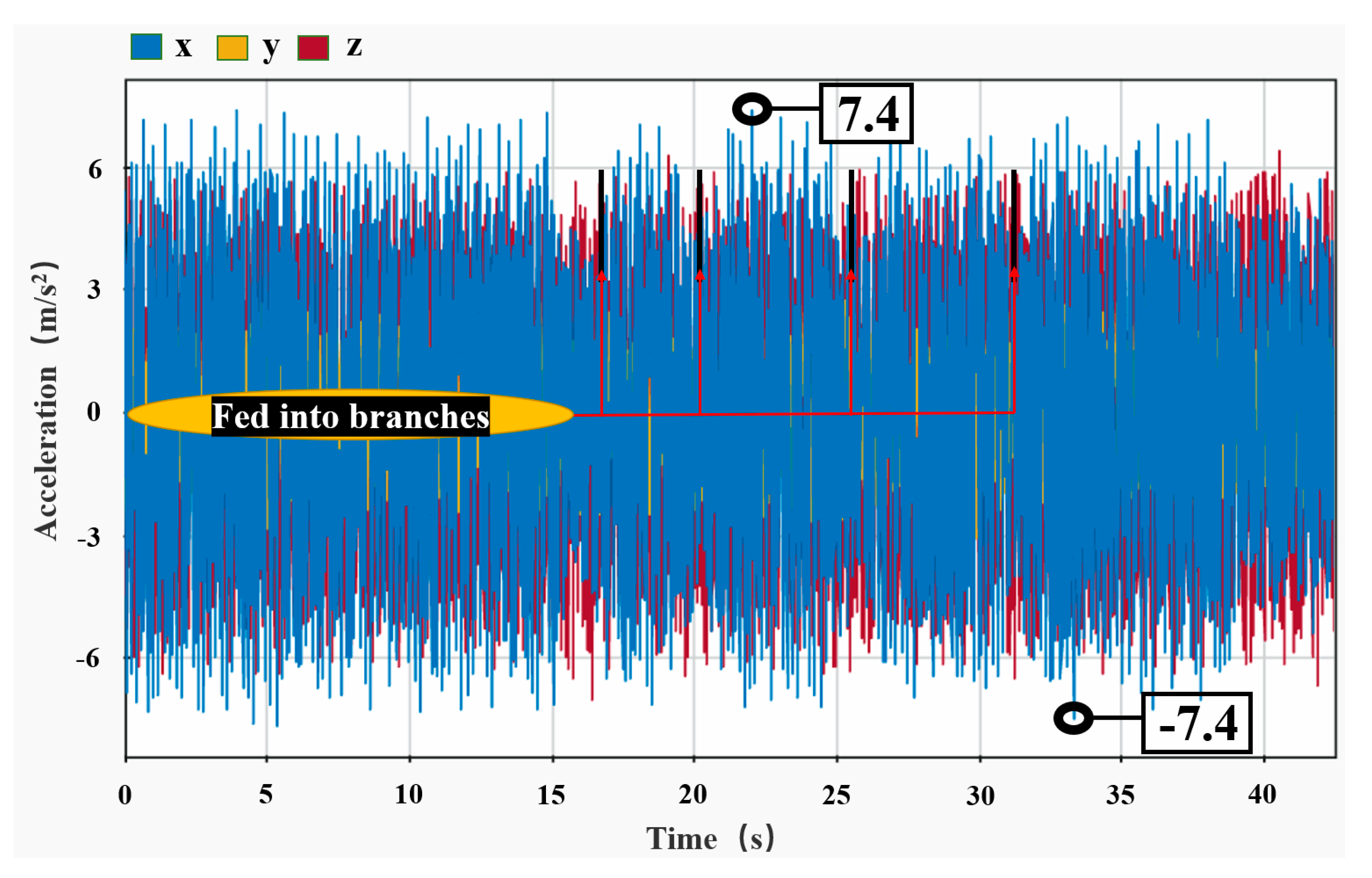
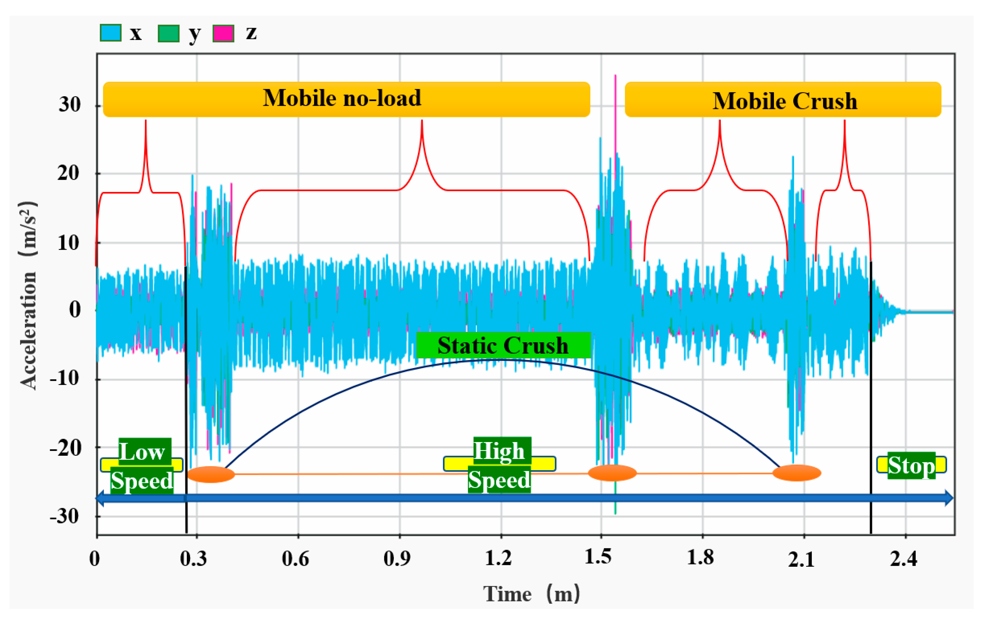
4.2. Vibration Test under Crushing Operation

Similar to the no-load test, the test points were still arranged as shown in Figure 7.
From Figure 13a–d, it can be seen that the chipper stationary crushing tractor walking protection frame three-way vibration is basically the same in the x-direction and y-direction, and the z-direction is slightly larger, with a value of 21.5 m/s2, left and right relative maximum amplitude of 39.9 m/s2, a stationary no-load x-direction maximum amplitude of 6.8 m/s2, and a relative maximum amplitude of 12.7 m/s2. The vibration amplitude differs greatly between the two states of no-load and crushing operation, which is mainly caused by the knife roller crushing the branch, and its cutting process is discontinuous, manifested by the work of impact on the branch, causing increased vibration, and the branch itself jumps after a cutting is completed, causing a further increase in vibration amplitude [36]. From Figure 13e, it can be seen that the frequency of vibration of the variable speed shaft of the traction mechanism is weaker than at no-load, and the main source of vibration has changed to the high-speed cutting motion of the knife roller [33].
The chipper mobile crushing operation process is not added to the new material, the crushed branches are fed at rest. From Figure 14a–d, it can be seen that the vibration amplitudes in the y-direction and z-direction are basically the same, and the vibration amplitude in the x-direction is the largest, with a value of 8.7 m/s2, and the relative maximum amplitude is 17.3 m/s2 in the left and right direction, which is more than half of the vibration amplitude during the stationary continuous feeding. Due to the process of stop feeding branches, the original discontinuous cutting intensifies, leading to mobile crushing operation in the process of z-direction vibration amplitude surge and radical retreat phenomenon, which may aggravate the unstable operation [37].
As shown in Figure 15, the amplitude of vibration in the x-direction was slightly larger than in the y-direction when the chipper was stationary, but the trend was similar, and the amplitude of vibration in the z-direction was much smaller than in the x-direction; the maximum vibration value in the x-direction was 7.4 m/s2, and the relative maximum amplitude of the left and right was 14.8 m/s2. When fed with branches, the x-direction vibration amplitude increased from 2–4 m/s2 to 5–7 m/s2, the y-direction vibration amplitude increased from 2–4 m/s2 to 4–6 m/s2, and the z-direction vibration amplitude remained basically unchanged.
As shown in Figure 16, the maximum amplitude of the x-direction vibration of the support rod during the crushing operation of the chipper occurred during the cutting of the branches, with a value of 16.5 m/s2 and a relative maximum amplitude of 27.7 m/s2 in the left and right direction; the x-direction and z-direction vibration amplitude fluctuated greatly during the crushing operation, where the x-direction vibration peaks and valleys were particularly pronounced, and the z-direction amplitude fluctuated within two values only, while the y-direction amplitude was basically unchanged and fluctuated within one value only.
The self-propelled monorail branch chipper crush vibration test results show that the maximum vibration occurs in the left and right direction of the travel protection frame, with a maximum value of 21.5m/s2; the next is the track support rods in the left and right direction, with a maximum value of 16.5m/s2; chipper pallet vibration is the smallest, and its maximum in the left and right direction with a maximum value of 7.4m/s2. Compared to the no-load condition, the walking protection frame and the support rod vibration level increase significantly, but the pallet table will remain unchanged. That means the chipper consolidation is stable, but the chipper introduces a lot of vibration hazards to the track system, and the maximum vibration level is 4.2 times higher than the above-mentioned orchard monorail truck. As with no-load, the maximum vibration is largely the same as the self-propelled monorail branch chipper. The difference is that the track system does not increase the vibration level of the chipper, but the chipper raises the vibration level of the track system to 4.2 times the original [28,32].

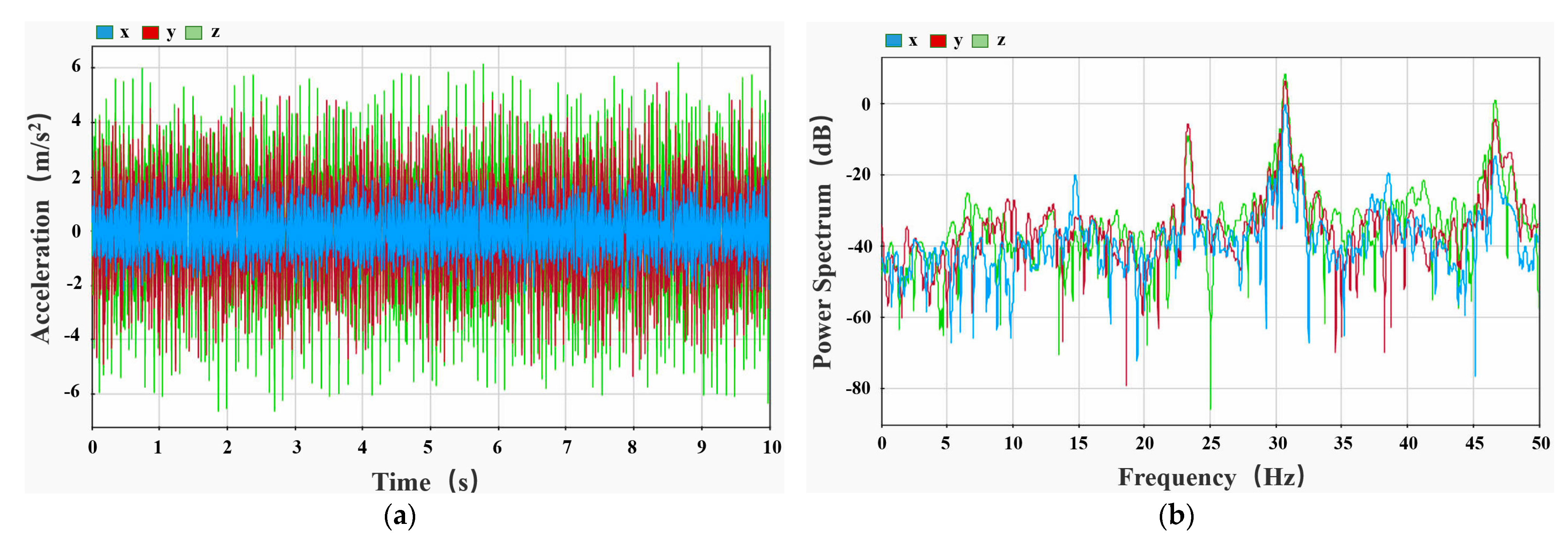
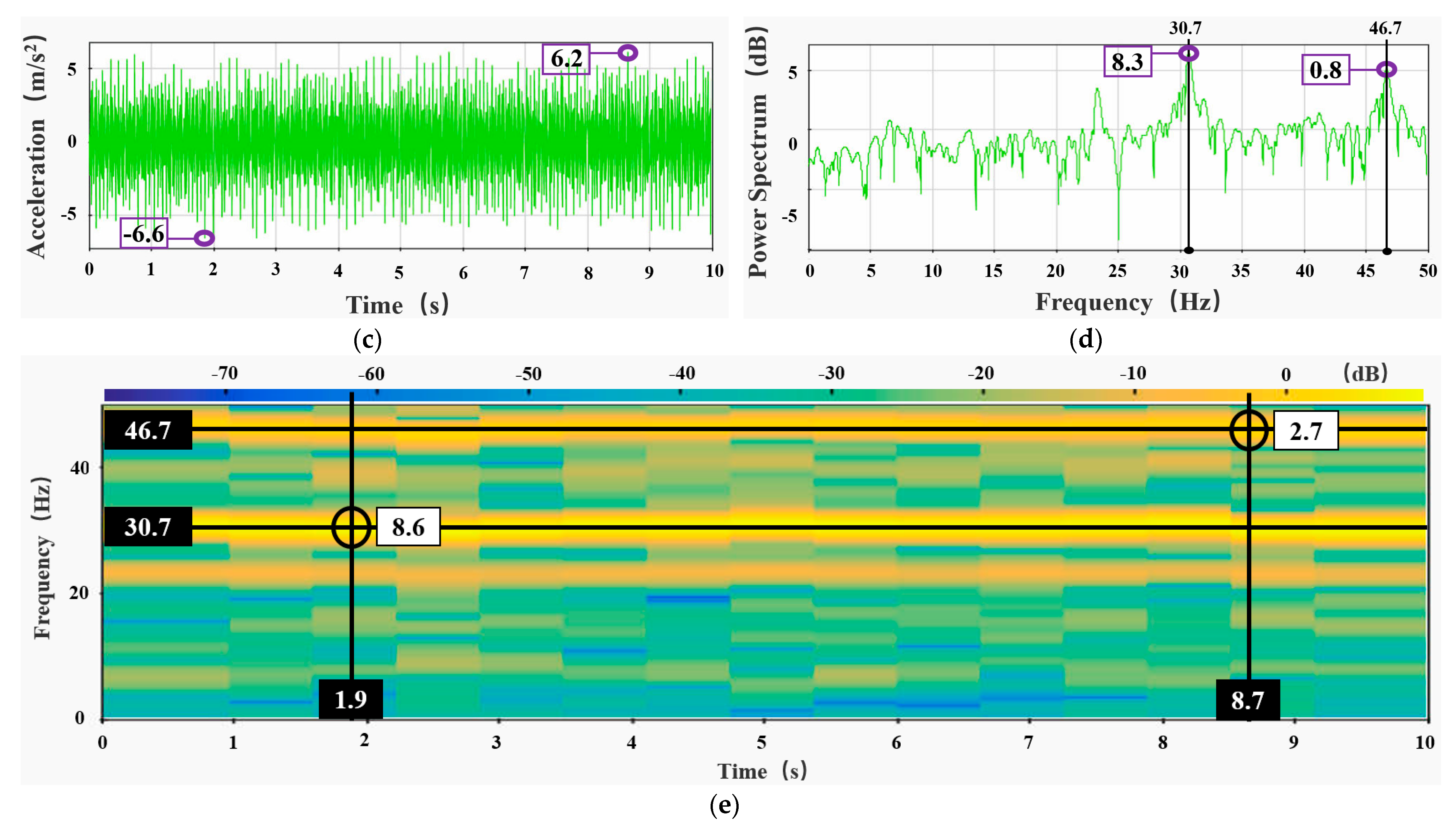
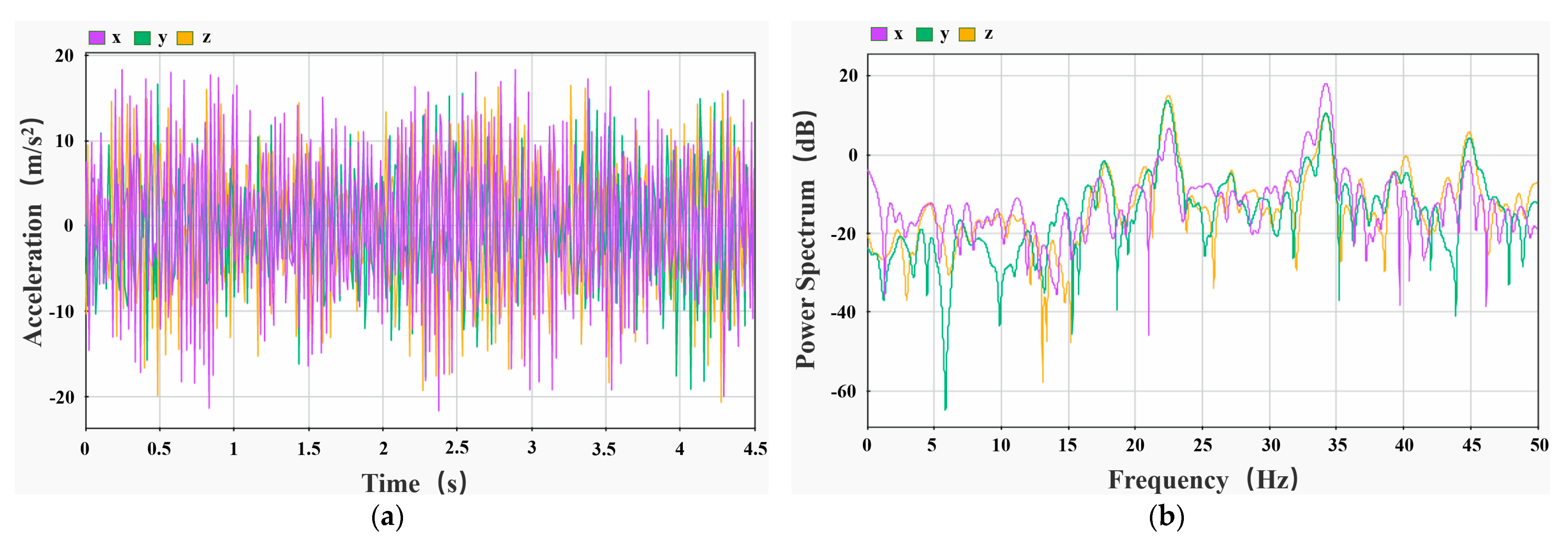
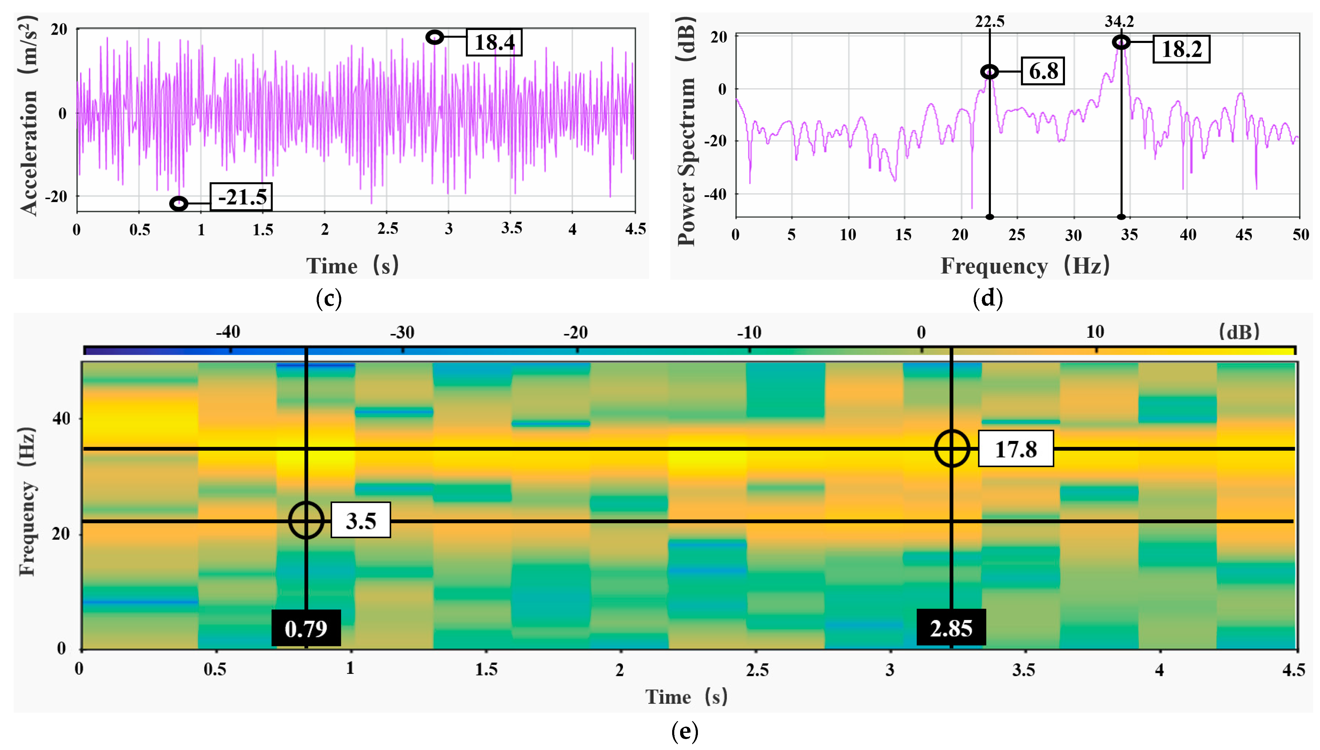
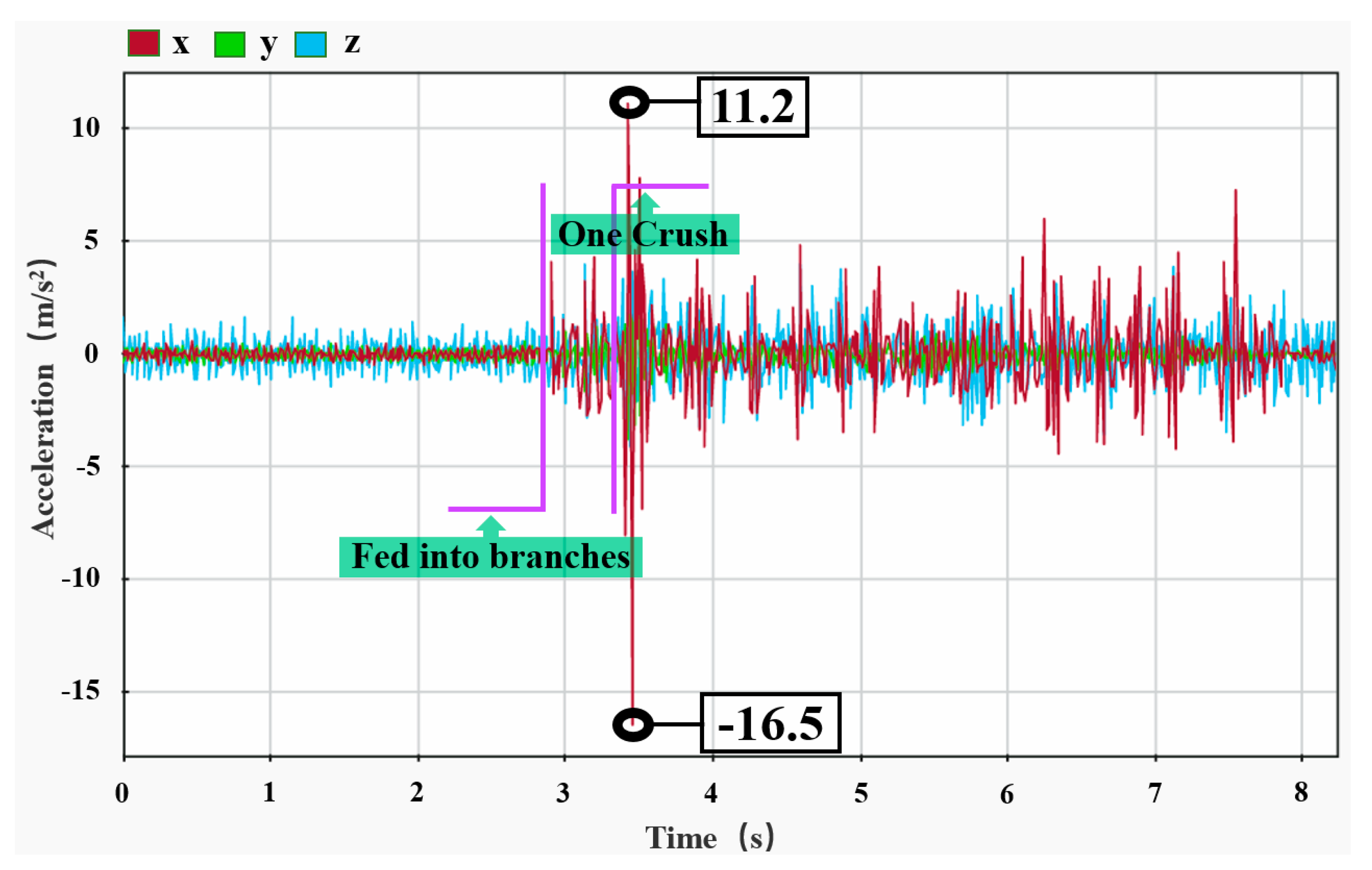
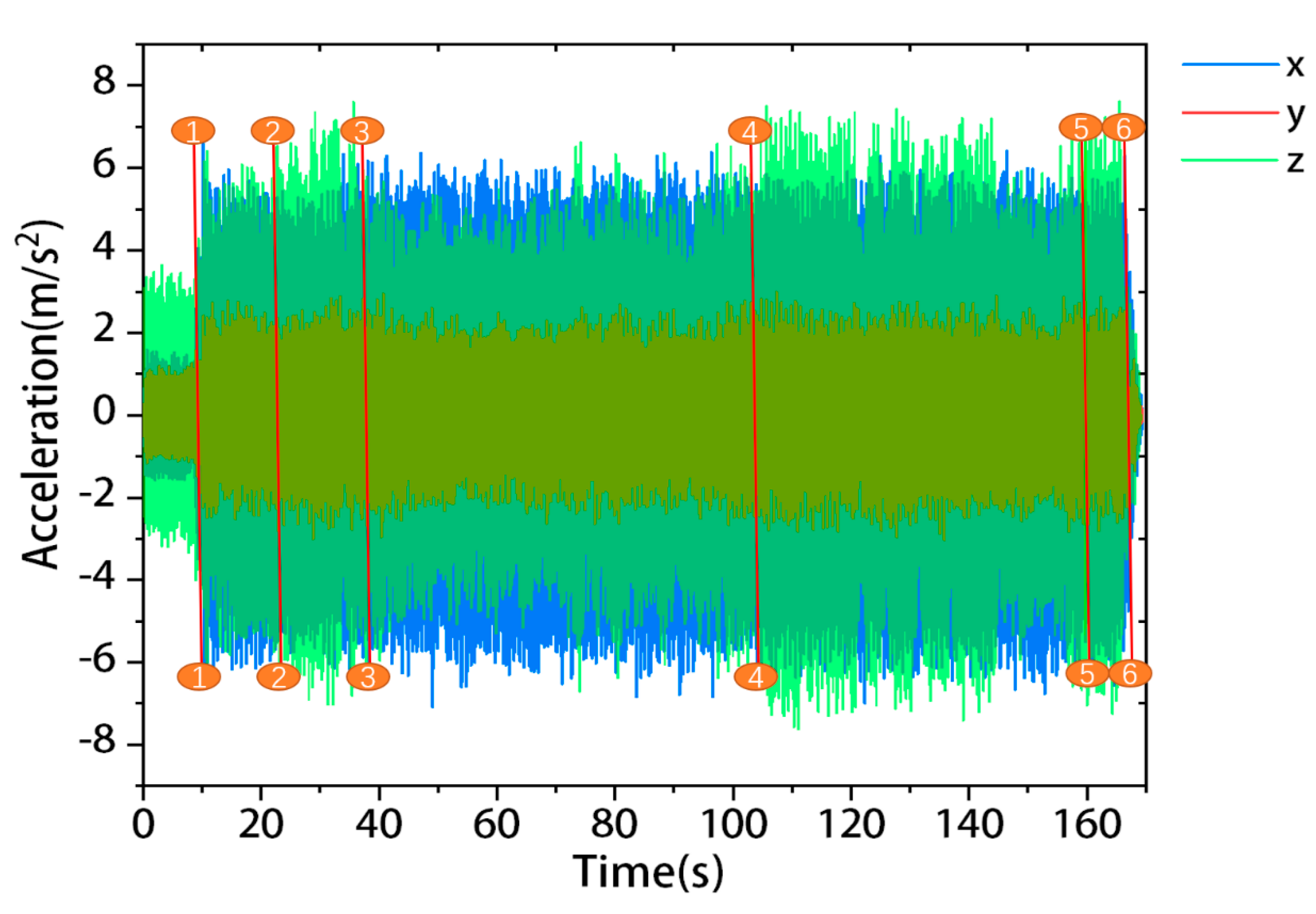
4.3. Multi-Stage Vibration Test

As shown in the Figure 17 three-way frequency diagram, in the low-speed idle, high-speed crushing, stationary and mobile crushing, and other operational processes, the overall x-direction vibration amplitude was the largest, but the largest amplitude appeared in the z-direction; this may be due to the hardness and diameter of the branch to be crushed by this cutting step, or because the flying knife cut at the branch knot and branch, resulting in a large jump of the knife roller. The x-direction vibration amplitude was larger than the low speed when the chipper was moving at high speed with no load, while the y-direction and z-direction were completely opposite; the vibration amplitude was more uniform in all three directions at high speed than at low speed. The vibration amplitude of the chipper in the three directions during the crushing operation was significantly higher than when it was unloaded, and its vibration pattern was affected by the number and diameter of the fed branches and other parameters due to the convenience of branch feeding when stationary, such as stationary crushing and mobile crushing vibration amplitude, mobile crushing performance for the thin peak form, and the peak and valley interval by the cutting speed decision. When the chipper has a small amount of residual fruit branches, the x-direction and z-direction vibration shape and the completely unloaded state was basically the same, while the y-direction vibration amplitude was slightly larger than when completely unloaded, so the main fluctuation when crushing fewer or smaller diameter branches is the up and down direction.
As shown in the Figure 18 three-way time–frequency diagram, the chipper started at a low speed at the first 0 s, and was set to a high speed at one line; when the knife roller speed was 2300 r/min, five branches were fed at a time between two and three lines, the basic crushing of branches was completed at three lines, no-load operation was completed between three and four lines, a random number of branches were fed several times between four and five lines, and the chipper stopped running at six lines. The chipper in the low-speed no-load and high-speed crushing operations showed an x-direction vibration amplitude larger than the other two directions, while the high-speed no-load z-direction showed the maximum vibration amplitude of the up and down direction. The chipper in the low-speed no-load and high-speed crushing operations showed that, in the x-direction, the left and right direction vibration amplitude was greater than the other two directions, while the high-speed no-load showed that, in the z-direction, the up and down direction vibration amplitude was the largest. It can also be seen from the graph that, in the z-direction, due to the chipper self-weight constraints, the vibration amplitude was relatively smooth; in the y-direction, due to rail stiffness constraints, the vibration amplitude was the smallest; the x-direction is the most variable and unstable in the whole operation process, which is due to the unbalanced rotation of the knife roller on the one hand, and the large span of the track support on the other [38].
As shown in the Figure 19 three-way time–frequency diagram, the chipper no-load z-direction vibration amplitude was the largest, x-direction and y-direction were smaller, and the amplitude was basically the same. Looking at the chipper high speed compared to low speed, there was no significant change in vibration amplitude in the x-direction and y-direction, but a slight increase in the z-direction. When the chipper was unloaded, the vibration amplitude in the z-direction was twice as large as that in the x-direction and y-direction, and the vibration in all three directions increased to different degrees when the branches were fed, with the x-direction rising from less than 2 m/s2 to 16 m/s2 and its amplitude far exceeding that in the z-direction.

5. Conclusions

We investigated the relationship between orbital length and intrinsic frequency and provided guidance for on-track mechanical design and track building applications. The modal analysis for different numbers of sections in the track system shows that the natural frequency is related to the number of sections in the track system under the condition that the bottom part of the support rod is rigidly fixed, the number of sections in the track increases, the natural frequency of each order decreases, and the vibration is weakened, in which the decrease of 1–4 sections is more obvious, and the change of vibration tends to be flat when a certain number is reached. For a distal short rail spur less than four sections, the number of lateral rods should be increased to reduce vibration in the run and operation.
The actual vibration test of the self-propelled monorail branch chipper shows smaller vibration amplitude when the transporter is running alone, and the vibration amplitude rises to 4.2 times when starting the chipper, with the vibration mainly from the chipping process. Analysis of engine combustion excitation frequency, knife roll interference frequency, and unbalanced cutting impact frequency compare the above results with the natural frequency of the orbital system. The results show that each frequency of the chipper does not overlap with the natural frequency of the orbital system, there are no resonance phenomena, and the increased track vibration of the chipper is a natural consequence rather than a design flaw.
We tested the actual vibration level of the self-propelled monorail branch chipper, and the results show that the prototype at rest, as well as mobile vibration amplitude difference, is not significant, while the crash operation compared to the no-load state vibration amplitude increased significantly, and its maximum vibration mostly occurred along the left and right direction of the cross rail with a maximum value of 21.5 m/s2 and a relative maximum amplitude of 39.9 m/s2. Excessive sidewall clearance of the drive wheel and load bearer wheel is the most important cause of left and right vibration. Therefore, in addition to increasing the stiffness and number of auxiliary support rods, optimizing sidewall wear of drive wheels and load bearer wheel to avoid increased clearance, and designing sidewall clearance adjustable structure, or creating a new way of fixing the wheels to the track are all important research directions.
In this paper, an orbital modal analysis was performed, compared with the chipper for each interference frequency. We summarized the relationship between orbital length and natural frequency, but no further verification has been performed. Field vibration tests are limited by the topography of the experimental field and failure to perform vibration tests at different climbing angles and turning radii, but the conclusions and optimization directions are still generalizable.

Author Contributions

Investigation, formal analysis and writing—original draft preparation, Y.G.; data curation, software, and resources, L.R.; conceptualization and project administration, X.H. and A.G.; methodology, S.J. and C.F.; writing—review and editing, supervision, and funding acquisition, Y.S. All authors have read and agreed to the published version of the manuscript.

Funding

We would like to acknowledge the financial support from the National Key Research and Development Plan of China for Intelligent Agricultural Machinery Equipment (2018YFD0700604, 2016YFD0701701), the Shandong Natural Science Foundation (ZR2019MEE092), the Innovation Team Fund for Fruit Industry of Modern Agricultural Technology System in Shandong Province (SDAIT-06-12), and the Shandong Agricultural University “Double First-class” Award and Subsidy Funds (SYL2017XTTD07).

Institutional Review Board Statement

Not applicable.

Informed Consent Statement

Not applicable.

Data Availability Statement

Not applicable.

Conflicts of Interest

The authors declare no conflict of interest.

References

  1. Song, Y.; Zhang, H. Development status and trend of domestic orchard transportation machinery in hilly and mountainous areas. J. Chin. Agric. Mech. 2019, 40, 50. [Google Scholar]
  2. Zheng, Y.; Jiang, S.; Chen, B.; LÜ, H.; Wan, C.; Kang, F. Review on Technology and Equipment of Mechanization in Hilly Orchard. Trans. Chin. Soc. Agric. Mach. 2020, 51, 1–20. [Google Scholar]
  3. Liu, H.; Liu, J.; Li, J. Comprehensive Utilization Technology of Orchard Pruning Branches. J. Agric. Mech. Res. 2011, 33, 218–221. [Google Scholar]
  4. Feng, H.; Yang, D.; Bai, S.; Xie, H.; Liu, X.; Pei, H. Characteristics of Degradation of Lignocellulose and Microbial Community Diversity during Fermentation of Wolfberry Branches Substrate. Trans. Chin. Soc. Agric. Mach. 2017, 48, 313–319. [Google Scholar]
  5. Feng, H.; Yang, Z.; Yang, D.; Qu, J.; Wang, C.; Guo, W. Parameter optimization of fermented substrate from wolfberry shoots. Trans. Chin. Soc. Agric. Eng. 2015, 31, 252–260. [Google Scholar]
  6. Shi, L.; Gu, J.; Pan, H.; Zhang, K.; Yin, Y.; Zhao, T.; Wang, X.; Gao, H. Improving enzyme activity by compound microbial agents in compost with mixed fruit tree branches and pig manure during composting. Trans. Chin. Soc. Agric. Eng. 2015, 31, 244–251. [Google Scholar]
  7. Guo, A.; Li, J.; Li, F.; Zhao, J.; Lu, Y. Process Optimization of Biomass Cushion Packaging Products and Its Properties. J. Mech. Eng. 2013, 49, 178–183. [Google Scholar] [CrossRef]
  8. Florkowski, W.J.; Nouve, Y.D.E.; Bauske, E.M.; Norton, N. Wood chip production and disposal choices: Landfill or recycle? J. Clean. Prod. 2022, 357, 131947. [Google Scholar] [CrossRef]
  9. He, Y.; Qian, W.; Wang, J.; Xiong, Y.; Song, P.; Wang, R. High value-added reutilization approach for waste biomass materials. Trans. Chin. Soc. Agric. Eng. 2016, 32, 1–8. [Google Scholar]
  10. Wang, F.; Liu, X.; Chen, L. Research status and development prospect of energy and high value utilization of biomass resources. Trans. Chin. Soc. Agric. Eng. 2021, 37, 219–231. [Google Scholar]
  11. Pang, Q.; Shi, T. Discussion of basic issues of drum chipper design. For. Grassl. Mach. 1997, 5–10. [Google Scholar]
  12. Micheletti Cremasco, M.; Giustetto, A.; Caffaro, F.; Colantoni, A.; Cavallo, E.; Grigolato, S. Risk assessment for musculoskeletal disorders in forestry: A comparison between RULA and REBA in the manual feeding of a wood-chipper. Int. J. Environ. Res. Public Health 2019, 16, 793. [Google Scholar] [CrossRef] [PubMed] [Green Version]
  13. Manzone, M. Energy consumption and CO2 analysis of different types of chippers used in wood biomass plantations. Appl. Energy 2015, 156, 686–692. [Google Scholar] [CrossRef] [Green Version]
  14. Facello, A.; Cavallo, E.; Magagnotti, N.; Paletto, G.; Spinelli, R. The effect of knife wear on chip quality and processing cost of chestnut and locust fuel wood. Biomass Bioenergy 2013, 59, 468–476. [Google Scholar] [CrossRef]
  15. Acuna, M.; Mirowski, L.; Ghaffariyan, M.R.; Brown, M. Optimising transport efficiency and costs in Australian wood chipping operations. Biomass Bioenergy 2012, 46, 291–300. [Google Scholar] [CrossRef]
  16. Guerrini, L.; Tirinnanzi, A.; Guasconi, F.; Fagarazzi, C.; Baldi, F.; Masella, P.; Parenti, A. A Plackett-Burman design to optimize wood chipper settings. Croat. J. For. Eng. 2019, 40, 81–87. [Google Scholar]
  17. Wang, Q.; He, L.; Zhou, Y.; Pan, Y.; Song, L.; Song, Z. Development status and trend of control system of the orchard branches crushing machinery. J. Chin. Agric. Mech. 2022, 43, 238–244. [Google Scholar]
  18. Wang, S. Design and Experiment of Orchard Branch Shredder; Northwest A&F University: Xianyang, China, 2021. [Google Scholar]
  19. Shen, X.; Liu, J.; Zhu, Z.; Yang, L. Parameter Optimization and Test of 9ZFS-350 Crawler Self-propelled Pruning Crusher. J. Agric. Mech. Res. 2022, 44, 78–82. [Google Scholar]
  20. Zhan, L.; Feng, X.; Ma, Y. Design and Experimental Study on the Crushing Mechanism of Crawler-type Pulverizers. J. Agric. Mech. Res. 2018, 40, 97–101. [Google Scholar]
  21. Gong, Y.; Song, Y.; Ren, L.; Zhang, H.; Han, Y. Design and field test of self-propelled branch crusher based on transportation track system in hilly orchard. J. Shandong Agric. Univ. 2021, 52, 692–696. [Google Scholar]
  22. Zhang, H. Development and Experiment of Frost Protection Smoke Machine Based on Transportation Track of Hilly Orchard Abstract; Shandong Agricultural University: Taian, China, 2021. [Google Scholar]
  23. Li, H.; Geni, M. Numerical analysis method and vibration characteristics analysis of complex composite structure de cotton rotor. J. Vib. Shock 2020, 39, 114–121. [Google Scholar]
  24. Li, X.; Zhao, G.; Yang, H. Nonlinear pre-stressed modal analysis for a composite beam considering influence of joint surface. J. Vib. Shock 2014, 33, 17–21. [Google Scholar]
  25. Xiao, X.; Li, H.; Li, X.; Wang, M. Modal and Transient Analysis of Threshing Cylinder Based on ANSYS Workbench. J. Agric. Mech. Res. 2016, 38, 46–50. [Google Scholar]
  26. Zhang, C. Vibration Test and Modal Analysis of Compartment of Monorail Transport Truck; Jiangsu University: Zhejiang, China, 2019. [Google Scholar]
  27. Lei, X.; Xing, C.; Wu, S. Mid-and high-frequency vibration characteristics of track structures. J. Vib. Eng. 2020, 33, 1245–1252. [Google Scholar]
  28. Chou, S.; Hu, Y.; Zhang, C. Vibration test and analysis of orchard monorail truck under multiple working conditions. J. Jiangsu Univ. 2021, 42, 207–214+228. [Google Scholar]
  29. Pelloso, M.F.; Pelloso, B.F.; de Lima, A.A.; Ortiz, A.H.T. Influence of harvester and rotation of the primary extractor speed in the agroindustrial performance of sugarcane. Sugar Tech 2021, 23, 692–696. [Google Scholar] [CrossRef]
  30. Wang, F.L.; Ma, S.C.; Xing, H.N.; Bai, J.; Ma, J.Z.; Wang, M.L. Effect of Contra-Rotating Basecutter Parameters on Basecutting Losses. Sugar Tech 2021, 23, 278–285. [Google Scholar] [CrossRef]
  31. Ma, L.; Wei, J.; Huang, X.; Zong, W.Y.; Zhan, G.C. Analysis of Harvesting Losses of Rapeseed Caused by Vibration of Combine Harvester Header during Field Operation. Trans. Chin. Soc. Agric. Mach. 2020, 51, 134–138. [Google Scholar]
  32. Zhao, X.; Li, X. Vibration analysis of chippers-pulverize. J. Inn. Mong. Agric. Univ. 2011, 32, 194–196. [Google Scholar]
  33. Ma, H.; Cui, H.; An, Z. Low-Frequency Vibration Characteristics in the Working Process of the Salix psammophila Chipper. Sci. Silvae Sin. 2018, 54, 177–190. [Google Scholar]
  34. Zhu, D.; Xue, R.; Cao, X. Vehicle random vibration analysis using a SDOF parametric excitation model. J. Vib. Shock 2022, 41, 79–86. [Google Scholar]
  35. Xu, W.; Li, B.; Liu, B.; Wang, S.; Li, Y.; Jia, L.; Zhao, Q. Shaking table test on multi-dimensional seismic response of nuclear power equipment considering different fixed conditions. World Earthq. Eng. 2022, 38, 89–95. [Google Scholar]
  36. Zak, G.; Wylomanska, A.; Zimroz, R. Alpha-stable distribution based methods in the analysis of the crusher vibration signals for fault detection. IFAC PapersOnLine 2017, 50, 4696–4701. [Google Scholar] [CrossRef]
  37. Ning, L.; Wang, H. Numerical Simulation Study on Cutting Parameters of Drum Chipper. China For. Prod. Ind. 2019, 56, 26–30. [Google Scholar]
  38. Hao, X.; Yu, C.; Liu, J.; Han, Q.; Zhai, J. Thermal-induced Bearing Stiffness and Clearance Variation Characteristics and its Effect on Vibration Response of Rotor System. J. Mech. Eng. 2022, 58, 147–165. [Google Scholar]
Figure 1. Overall structure of the self-propelled monorail branch chipper: 1. Chipper pallet. 2. Drive system of the chipper. 3. Feed channel. 4. Chipper engine. 5. Outlet. 6. Control box. 7. Control rod. 8. Traction engine. 9. Cross rail. 10. Main support rod. 11. Auxiliary support rod. 12. Pallet. 13. Drive wheel. 14. Guide wheel. 15. Protective frame for travel mechanism. 16. Load bearer wheel.
Agriculture 13 00101 g001
Figure 2. Statics analysis model diagram of the track system.
Agriculture 13 00101 g002
Figure 3. Natural frequency variation of orbits with different number of knots.
Agriculture 13 00101 g003
Figure 4. The mass normalized vibration modes of different section tracks.
Agriculture 13 00101 g004
Figure 5. Results of the first eight modal analysis of 10 tracks.
Agriculture 13 00101 g005aAgriculture 13 00101 g005b
Figure 6. Knife roller structural representation.
Agriculture 13 00101 g006
Figure 7. Schematic diagram of vibration test points.
Agriculture 13 00101 g007
Figure 8. Results of static no-load test for the walking protection frame of the chipper tractor: (a) time–frequency diagram; (b) amplitude–frequency diagram.
Agriculture 13 00101 g008
Figure 9. Results of the no-load test on the moving protection frame of the chipper tractor: (a) time–frequency diagram; (b) amplitude–frequency diagram.
Agriculture 13 00101 g009
Figure 10. Results of the static no-load test on the carrier platform of the chipper: (a) three-way time-frequency diagram; (b) three-way amplitude-frequency diagram; (c) time-frequency diagram in the z-direction; (d) amplitude-frequency diagram in the z-direction; (e) time-frequency domain diagram in the z-direction.
Agriculture 13 00101 g010aAgriculture 13 00101 g010b
Figure 11. Results of static no-load test of support rod.
Agriculture 13 00101 g011
Figure 12. Results of the no-load test for the moving support rod.
Agriculture 13 00101 g012
Figure 13. Static comminution test results of the tractor travel protection frame: (a) three-way time-frequency diagram; (b) three-way amplitude-frequency diagram; (c) time-frequency diagram in the x-direction; (d) amplitude-frequency diagram in the x-direction; (e) time-frequency domain diagram in the x-direction.
Agriculture 13 00101 g013aAgriculture 13 00101 g013b
Figure 14. Test results of the moving comminution of the tractor protection frame: (a) three-way time-frequency diagram; (b) three-way amplitude-frequency diagram; (c) time-frequency diagram in the x-direction; (d) amplitude-frequency diagram in the x-direction; (e) time-frequency domain diagram in the x-direction.
Agriculture 13 00101 g014aAgriculture 13 00101 g014b
Figure 15. Static comminution test results of the carrier platform of the chipper.
Agriculture 13 00101 g015
Figure 16. Static chipping test results of the support rod.
Agriculture 13 00101 g016
Figure 17. Operation time frequency diagram of the tractor protection frame of the chipper.
Agriculture 13 00101 g017
Figure 18. Time–frequency diagram of the static no-load and chipping process of the carrier platform of the chipper.
Agriculture 13 00101 g018
Figure 19. Frequency diagram of the static no-load and chipping time of the support rod.
Agriculture 13 00101 g019
Table 1. Main technical performance parameter table.
ParametersNumerical
Whole machine size (L × W × H)/(cm × cm × cm)150 × 80 × 100
Operation slope/(°)≥25
Operation speed/(m/s)0.5~1
Chipper supported power/(Kw)2.94
Operation efficiency/(m3/h)1.1~2.1
Table 2. Materials and properties.
MaterialDensity (kg/m3)Modulus of Elasticity (Pa)Poisson’s Ratio
Q23578602.12 × 10110.288
Disclaimer/Publisher’s Note: The statements, opinions and data contained in all publications are solely those of the individual author(s) and contributor(s) and not of MDPI and/or the editor(s). MDPI and/or the editor(s) disclaim responsibility for any injury to people or property resulting from any ideas, methods, instructions or products referred to in the content.

