Article

Coupled Bionic Design of Liquid Fertilizer Deep Application Type Opener Based on Sturgeon Streamline to Enhance Opening Performance in Cold Soils of Northeast China

College of Engineering, Northeast Agricultural University, Harbin 150030, China
*
Author to whom correspondence should be addressed.
Agriculture 2022, 12(5), 615; https://doi.org/10.3390/agriculture12050615
Submission received: 13 March 2022 / Revised: 23 April 2022 / Accepted: 25 April 2022 / Published: 26 April 2022

Abstract

:
Liquid fertilizer has many advantages, such as low production cost and little environmental pollution. Liquid fertilizer open furrow strip application method is widely used in fertilizer application operation. The widely used core-share furrow opener has a high operational resistance, disturbing the soil, hurting the crop roots, causing the liquid fertilizer to volatilize and deteriorating the fertilization effect. In this study, based on the streamline curve of the sturgeon body, we designed several bionic sturgeon liquid fertilizer deep application openers by combining bionics and analyzed the effects of several openers under different operating speeds on open furrow resistances and soil disturbance based on the discrete element method. The mechanism of open furrow resistances reduction and efficient soil backfill of the bionic structure were verified by indoor soil bin tests. The test results show that, compared with the core-share type furrow opener, both open furrow resistances and soil disturbance of the bionic sturgeon liquid fertilizer deep application opener are smaller. This study provides theoretical and practical references for the design of liquid fertilizer deep application openers.

1. Introduction

Since the rise of the Green Revolution, most countries in the world have begun to vigorously promote modern planting modes, strengthen irrigation and management, and raise the amount of fertilizer and pesticide application to increase the unit and total area output [1,2,3]. The excessive use of chemical fertilizers will have an impact on the agricultural ecological environment, including soil pollution and agricultural water pollution [4,5,6,7]. Therefore, it is essential to maintain sustainable agricultural development, protect soil ecosystems and promote the rational use of chemical fertilizers [8,9,10]. Regarding crop production and planting, the most common method of fertilizer application is to throw solid granular fertilizer, but the application of solid fertilizer on the surface of soil is very volatile. This causes the loss of nutrients and environmental pollution, and affects the crop absorption rate [11,12]. Compared with the solid fertilizer, liquid fertilizer deep application technology in the near root of the crop can significantly improve the efficiency of fertilizer utilization and reduce the volatilization and environmental pollution of fertilizer [13]. However, as for the deep application of liquid fertilizer, many problems are found in the opener, an important part of the project, such as high open furrow forces, large disturbance to soil, and low efficiency. Excessive open furrow forces of the furrow opener will cause excessive energy consumption. Excessive disturbance to the soil will reduce the soil backfill rate and inconsistent backfill depth, which will lead to excessive volatilization of liquid fertilizer, environmental pollution, and it will influence crop absorption [14,15,16]. The current working speed of the deep application machine of liquid fertilizer is typically limited to 6 km h−1, and the high speed will cause excessive disturbance of soil and affect the effect of fertilization [17,18].
Many scholars evaluate the performance of the new opener through computer simulation test. Computer simulation test can reduce the test steps, save the test cost, and reduce the resources required for the design and manufacture of the furrow opener. A discrete element method (DEM) is a numerical simulation method for dealing with discontinuous media first proposed by Cundall in the 1970s, which is used to analyze the mechanical behavior of a granular population [19]. Since the DEM was put forward, it has been proved to be effective by many scholars for building the coupling model of the furrow opener soil interaction, and it is an effective way to study the granular media and dynamics and optimize the design [20].
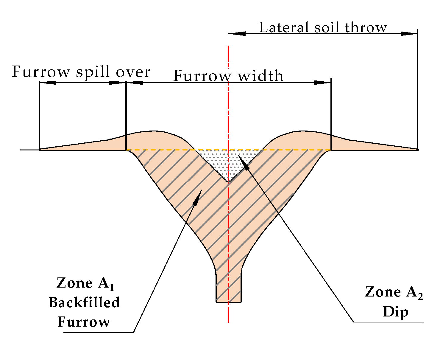
At present, many scholars have studied the characteristics of soil disturbance caused by the furrow opener and defined soil disturbance. Zhao, Liu, Tan, Cao, Zhang, and Yang [18] selected the key parameters of furrow profile disturbance width and soil backfill depth to measure the degree of soil disturbance. This method only measures the surface parameters of soil furrow profiles, and cannot further quantify the internal disturbance of soil furrow profiles. Francetto et al. [21] measured the disturbance degree of the soil by measuring the raised area (EA), maximum depth (MFD) and width (MFW) of the furrow profile. This method comprehensively quantifies the disturbance of the opener to the soil, but does not further refine the furrow profiles. In this study, the method of Ucgul et al. [22] is adopted. The soil transportation (volume density reduction) and movement (spatial position change) will be caused by the furrow opener in the process of opening.
Bionics is a comprehensive discipline, which applies the laws and mechanisms found in biology to solve the problems in engineering technology [23]. After continuous development, its related research has gradually become the focus of academic research [24,25]. Bionic design methods include curve extraction and fitting by contour projection, 3D reverse engineering model extraction and so on. At present, many researchers design furrow opener shape based on Bionics, and carry out a lot of research. For example, Zhao, Liu, Tan, Cao, Zhang and Yang [18] designed a new type of furrow opener to reduce the working open furrow forces of the furrow opener through the bionic research on the head curve of swordfish. The research showed that when the water content is 12% ± 1%, the working open furrow forces, the width of soil disturbance and the depth of Furrow backfill increase with the rise of trench depth. When the depth of the furrow is 60 mm, the opening furrow forces increase with the rise of water content, however having no obvious effect on the width of soil disturbance and the depth of furrow backfill. Based on the high efficiency and low open furrow forces penetration structure of the badger’s canine tooth surface, Honglei et al. [26] designed four kinds of sliding furrow openers, and a comparative test analysis was carried out. The results showed that the optimized sliding openers have lower operation open furrow forces than the core-share furrow opener. Dickinson [24] designed nine kinds of cassava digging shovel by extracting the forepaw contour of oriental mole and obtained the optimal scheme through experiments, which effectively realized the lightweight of a digging shovel and improved the mechanical performance. These studies provide a theoretical basis for the shape design of the furrow opener. Although many scholars have conducted a lot of research on the bionic furrow opener, most of the research is the application of bionics for designing the furrow opener’s soil penetration curve. There is little research on the influence of the bottom profile curve structure of the furrow opener on the working open furrow forces and soil disturbance in the process of operation.
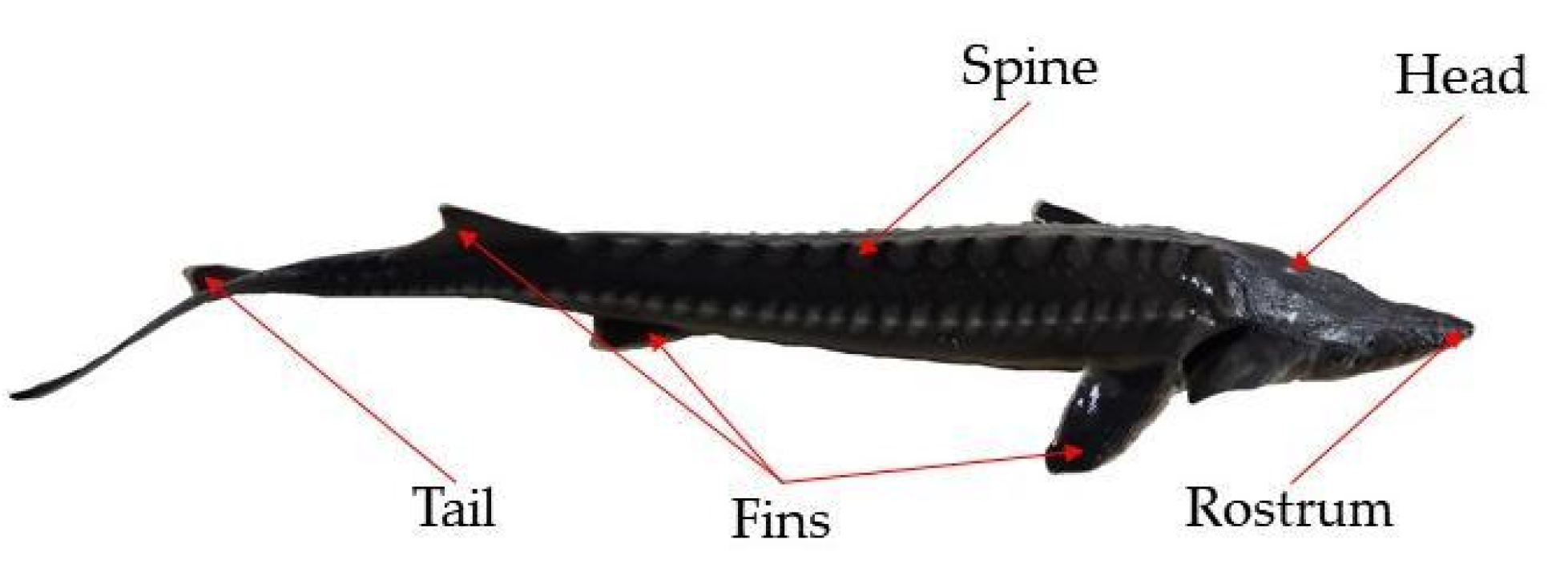
In nature, many animals have streamlined body curves. Sturgeon is an ancient fish species that has lived underwater for millions of years. It has evolved a well-streamlined drag reduction body structure and has a unique spindle body shape. The migratory sturgeon will go up the river for more than 3000 kilometers and return to its birthplace to breed its offspring [
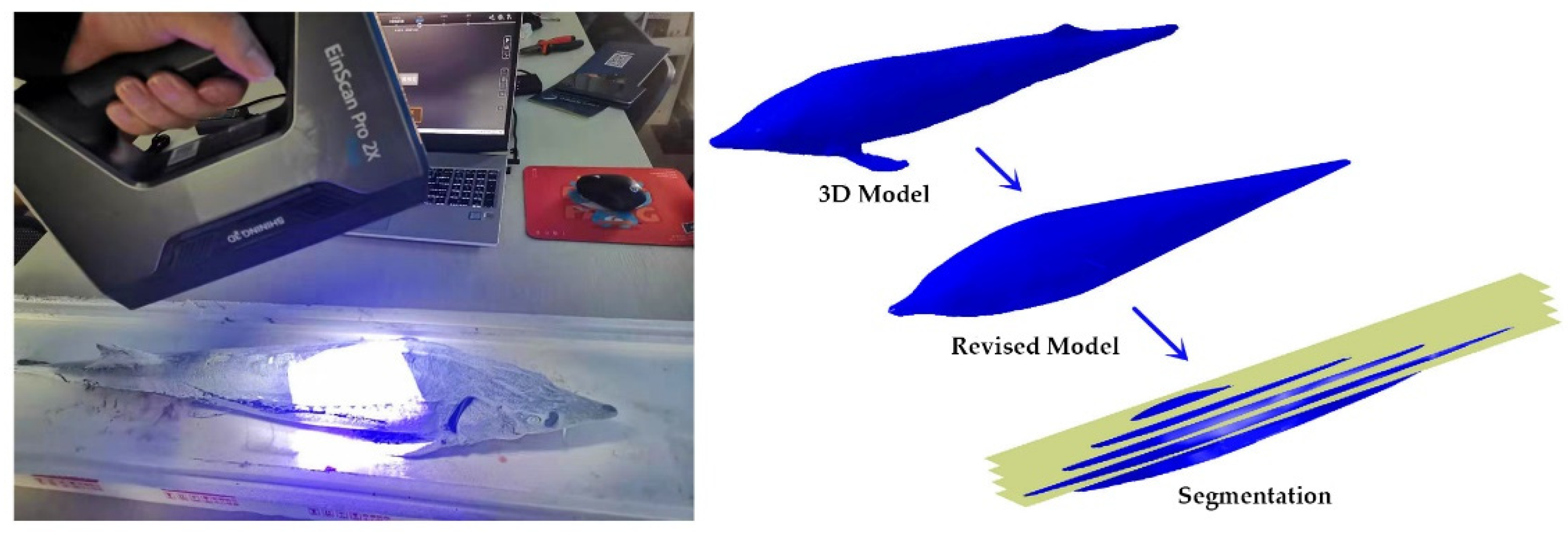
27]. It can be seen that sturgeon has good drag reduction characteristics during swimming. Based on the bionic extraction, Wenfeng et al. [28] constructed the sturgeon head contour curve to realize the bionic structure of the blade, and the drag reduction mechanism was analyzed.
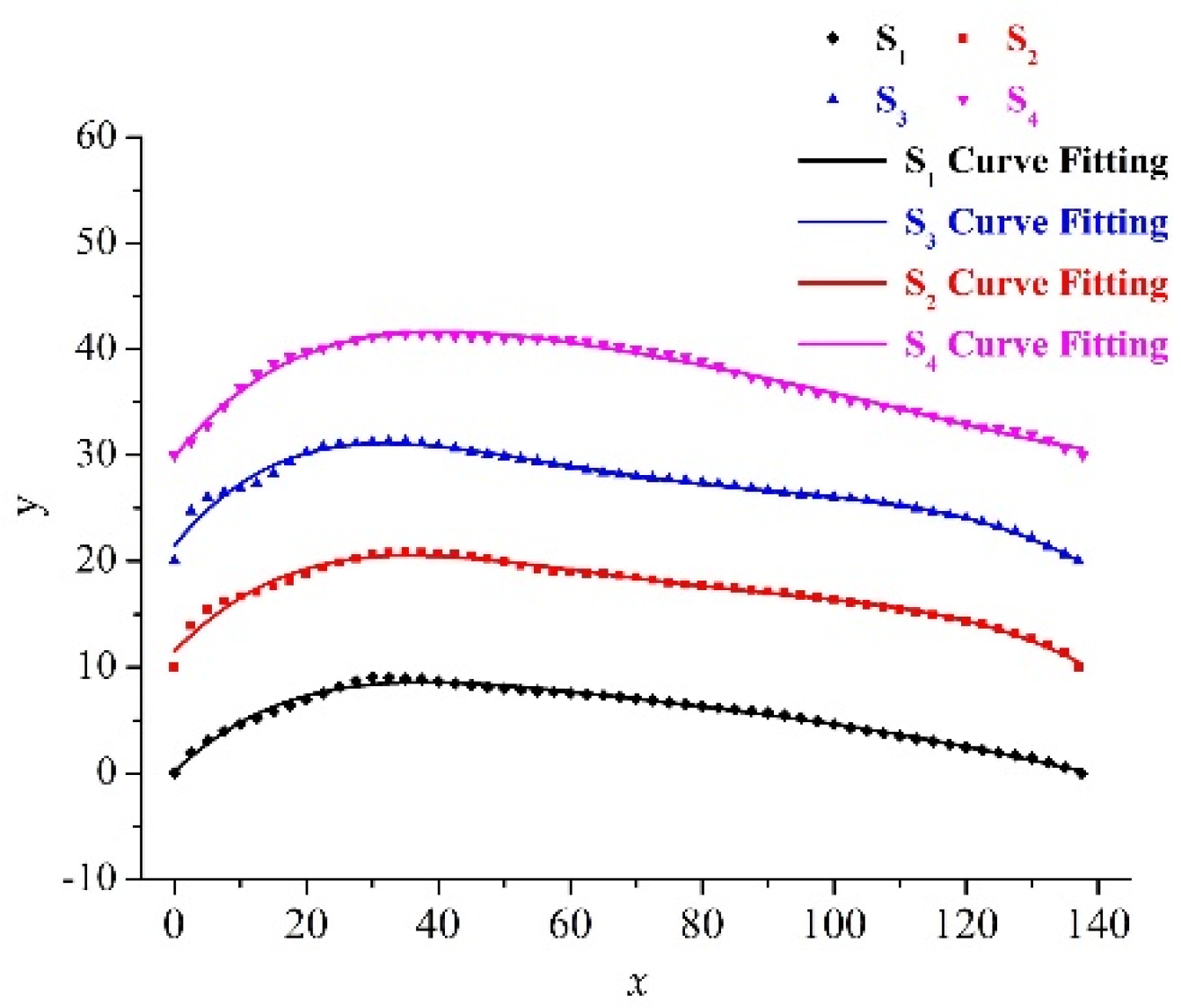
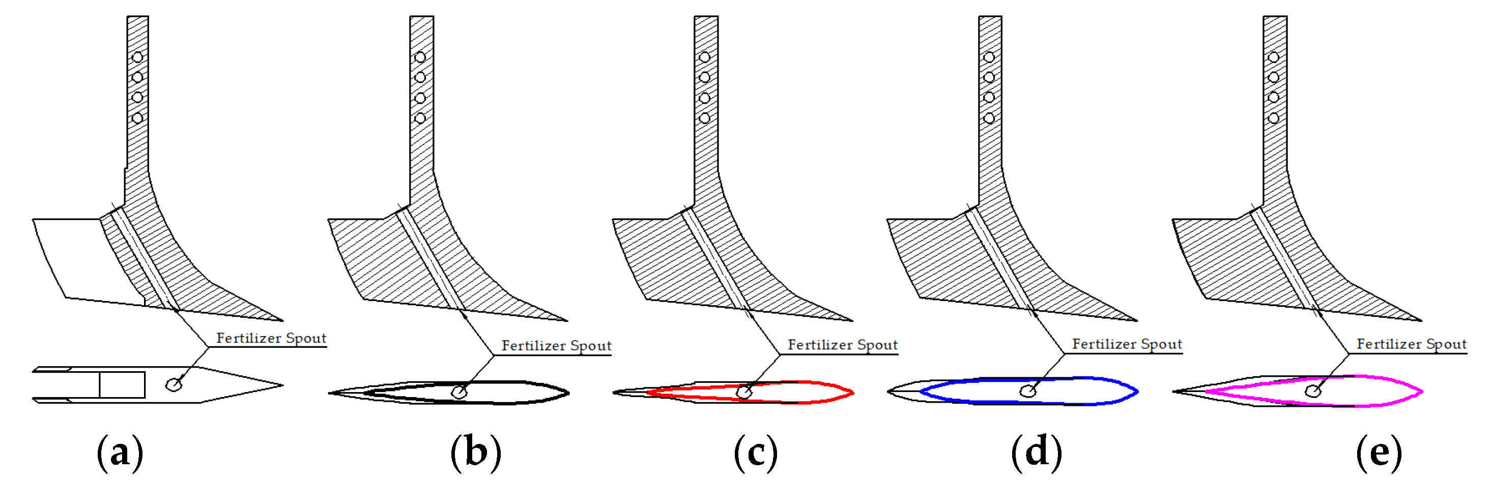
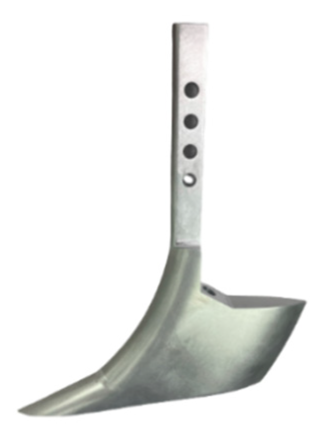
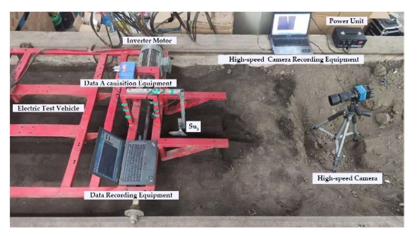
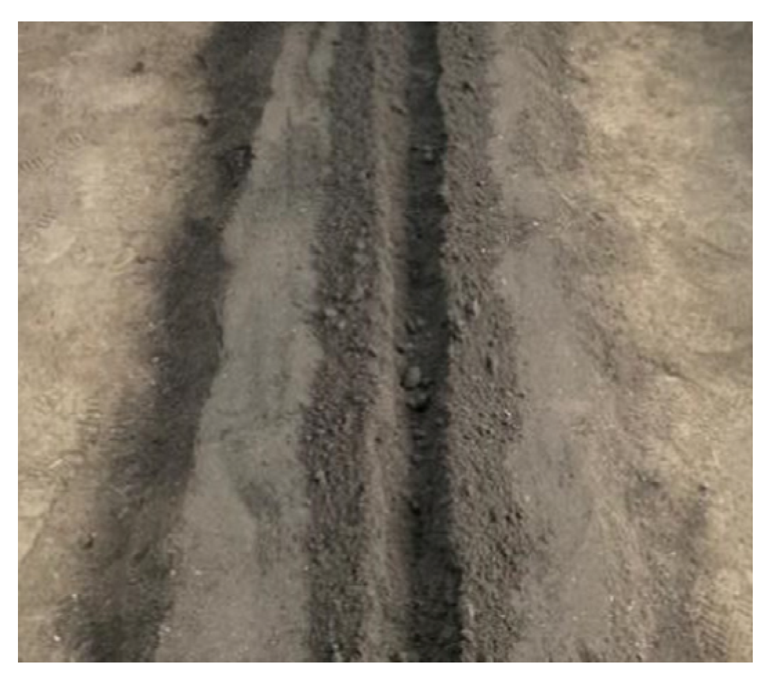
In this study, a comparison test was conducted between the core-share opener commonly used with liquid fertilizer and the bionic sturgeon liquid fertilizer deep application opener by the discrete element method, and the vertical and horizontal forces were extracted by EDEM2020 software. The furrow profile was quantified by extracting the trench profile with a grid composed of porosity parameters to analyze the key furrow profile parameters affecting the effect of liquid fertilizer deep application operation with speed and bottom profile line The pattern was analyzed. Finally, a bench test was conducted and compared with the simulation results.

2. Materials and Methods

2.1. Shape Design of Bionic Furrow Opener

2.1.1. Bionic Prototype

Sturgeon is the general name of 27 species of sturgeons belonging to the family Acipenseridae. Although sturgeons are different in size, their body shape curves are almost the same. Hence, they meet the requirements of a similar geometric structure [29]. The body structure of sturgeon is shown in Figure 1. In this study, the natural dead sturgeon from the national seed factory of Amur sturgeon in Fuyuan, Heilongjiang Province, is selected. EinCcan Pro 2x plus high-precision (0.05 mm) hand-held non-contact fine scanner was used to scan the sturgeon surface for the sturgeon surface feature point cloud data. Then, Geomagic Design X software was used to reverse engineer the point cloud data. The 3D model of sturgeon includes the rostrum, head, spine, fins, tail and other parts. Through the lofting and guiding function of Geomagic Design X software, the fin, tail, and other parts were removed and replaced by the adjacent domain fitting surface extension. Finally, the 3D model of the sturgeon could be edited. It was convenient to extract sturgeon body shape curve data at a later stage.
In this study, the shape of the furrow opener was designed based on vertical view. Yan, Su, Zhang, Hang, Zhou, Liu and Wang [29] adopted three schemes, labeled Stop1, Stop2, and Stop3, to comprehensively investigate the streamline geometric characteristics of sturgeon. These schemes considered the influence of sturgeon mouth structure changes on its streamline structure. When the bionic model was constructed along the top view direction, the geometric structures of different sections of the bionic model were different. Therefore, the physical model of the bionic model was established through four parts in this study. Based on the plane of sturgeon mouth and tail top, the 0,1/4,2/4, and 3/4 sections of the total height of the sturgeon model were selected and named S1, S2, S3 and S4 respectively. Then, the body curve data of different sections were obtained. The cusp end of sturgeon mouth to the cusp end of sturgeon tail was taken as the x-axis, and the vertical direction is y-axis. The rectangular coordinate system was established. The curve was divided into 55 equal parts along the x-axis, and the position coordinates of the curve relative to the x-axis and y-axis reference line were recorded. Finally, according to the relative position coordinates, polynomial curve fitting was used for mathematical analysis, and the curve equation was obtained. The scanning process and 3D model processing method were shown in Figure 2. The curve equation was shown in Table 1, and the image of fitting curve function was shown in Figure 3.

2.1.2. Design of Furrow Opener

According to the Chinese Academy of Agricultural Mechanization Industry [30], the soil entry curve of the fertilizer opener was selected as the ridge line, and S1, S2, S3, and S4 were used as the contour line at the bottom of the furrow opener. According to the requirements of agricultural technology, the angle of soil gap was 6°. The height was 150 mm, and the auxiliary installation structure was designed. The bionic sturgeon liquid fertilizer deep application furrow opener was designed and modeled by CATIA software. The structure of the furrow opener was shown in Figure 4. The full-factor experimental designs of four kinds of bionic sturgeon liquid fertilizer deep application furrow openers (Su1, Su2, Su3, and Su4) and core-share furrow opener (Su0) were carried out. As shown in Table 2 and Table 3, the design was used to evaluate the influence of different structures of the furrow opener on the opening furrow forces and soil disturbance, and to explore its mechanism.

2.2. Discrete Element Simulation Test

The furrow opener was tested in a discrete element virtual soil bin. The soil in the bin represents the characteristics of black soil in the main agricultural crops planting areas in northeast China. The conditions and equipment of discrete element simulation test were shown in Table 4.

2.2.1. Selection of Simulation Model and Calibration of Parameter Calculation

In the virtual experiment, the selection of particle parameters had a great influence on the accuracy of the experimental results. The black clay in northeast China features low porosity, more clay particles, higher humus content, and complex soil properties. The moisture content of crops during the cultivation period is generally between 10% and 13%. In this study, the soil type with 13% moisture content is selected for the discrete element experiment [31]. The Hertz Mindlin with JKR condensation model in EDEM software is used, which considers the cohesive force between wet particles and agglomerated materials, such as soil particles. In the Hertz Mindlin with JKR condensation model, the force that two particles need to be separated depends on the liquid surface tension γs and wetting angle, as shown in Formula (1) [32]:
Fpullout = −2Πyscos (θ)Ri1/2Rj1/2,
where Fpullout is the force required to separate two particles (N), θ is the contact angle (rad), R is the particle radius (mm).
The selection of simulation parameters was shown in Table 5. The method used by Ucgul, Fielke and Saunders [22] was used to calibrate the angle of repose of simulated soil by comparing with the actual angle of repose of soil and constantly modify the parameters of EDEM2020 software to match the target angle of repose of soil (China northeast black soil). The measurement method used by Barr et al. [33] was used. Firstly, the soil was dried at 105 °C for 24h, then water was added into the soil and made it uniform. The water content was controlled at 13%. The soil was loaded into a pipe with a height of 580 mm and an inner diameter of 150 mm. The soil was compacted by applying load, and the density was controlled at 1280 kg m−3. Then the pipe was pulled up at a constant speed of 500 mm s−1, and the released soil naturally accumulated. The average angle of repose was 28.33°. The standard deviation was 0.31° (Figure 5a). In the virtual test, the angle of repose of soil was measured after the particles were completely static after repeating the above test, and the rolling friction coefficient and surface energy parameters between soil particles were continuously modified until the angle of repose reached 28.33° (Figure 5b). The best coefficient was soil particle rolling coefficient 0.38 and surface energy parameter was 0.5 J m−2.

2.2.2. Establishment of Simulation Model

The experiment was simulated by EDEM software for black soils in the northeast at 13% moisture content (density of 1280 kg m−3). Using the Barr, Ucgul, Desbiolles and Fielke [33] experimental method, spherical particles randomly generated using 2–3 mm particles were distributed in a virtual soil bin, and then virtual plane loads were applied to compress to the desired density to match the soil bulk density of the physical soil bin, and the virtual plane was lowered to below the target height of 1 mm to prevent the virtual plane from rising due to particle expansion. Three sections of the virtual soil bin were created (Figure 6). One of them was 1000 mm to ensure soil equilibrium; 700 mm zone was used for data collection (to prevent intermittent soil flow caused by the furrow opener from causing variation in test results); and 300 mm zone was used to eliminate defects caused by the furrow opener leaving the soil bin. Setting the width and depth of the soil bin at 400 mm and 140 mm was performed to eliminate the effect of the soil bin boundary on particle movement. A 100 mm wide collection zone was added on both sides of the soil bin to collect the laterally thrown soil particles. Each furrow opener was imported into the virtual environment separately before the test to simulate the desired working depth and working speed.

2.3. Simulation Experiment Design

2.3.1. Determination of Opening Furrow Resistances

Figure 7 shows the curves of determination of opening furrow force with the operation time in the discrete element test at an operation speed of 10 km h−1 and a fertilizer application depth of 80 mm. The red dashed line in Figure 7 is within the data collection area, and the blue dashed line is the average of the determination of opening furrow force in the data collection area as determination of opening furrow force under this operating condition.

2.3.2. Determination of Furrow Profile Parameters

In this study, the furrow profile was extracted by grid box. A porosity grid was established in the data collection area of the soil bin to extract the furrow profile [33], as shown in Figure 8.
After extracting the furrow profile, the parameters of A1, A2, A1 + A2, Furrow backfill, Furrow width, Lateral soil throw and Furrow spill over could be extracted, as shown in Figure 9. Furrow backfill and Furrow spill over are defined by Equations (2) and (3) respectively.
Furrow backfill = A1/(A1 + A2)
Furrow spill over = Lateral soil throw−Furrow width/2

2.4. Indoor Soil Bin Test

Considering the error of the simulation test and to verify the reliability of the discrete element test, a solid of Su3 was fabricated using CNC technology in this study (Figure 10), and Su3 was tested by indoor soil bin test at the Agricultural Machinery Laboratory of Northeast Agricultural University (126°43′25 N, 45°44′27 E). The soil in the soil bin was the soil shown in Table 6.
The soil needed to be laid in layers to ensure that each layer had the same physical properties, such as bulk weight and water content. The maximum depth of liquid fertilizer deep trenching test was 80 mm, so it was decided to lay 30 mm of base soil first, and the upper layer was laid every 20 mm soil layer and compacted twice with 10 kg roller for reciprocation to ensure uniform soil bulk density in each layer. The total depth of the soil in the final bin was 140 mm, and five samples were randomly selected to determine the soil properties. The measured soil capacity of the sampled soil was 1280 kg m−3, which was similar to the soil parameters of the discrete element test.
The experiment used a sensor and data processing system installed on a motorized test vehicle to collect and organize the test data (Figure 11). To avoid signal instability, the force measurement system was calibrated and zeroed prior to conducting the formal tests. At the end of each test run, all the soil above the subgrade soil was removed, collated and relaid. The test equipment models are shown in Table 7.
Tests were conducted at 80 mm operating depth, 4 km h−1, 6 km h−1, 8 km h−1 and 10 km h−1. Data were collected and screened after the tests to remove individual error points (mutation values) and obtain test data. The soil condition after the operation is shown in Figure 12 and Figure 13. After the furrow opener operation, five cross sections were randomly selected in the data collection area at five locations, and a white board was inserted without disturbing the soil, and the outer furrow was depicted using a marker, and the furrow was depicted twice after the end of the operation by removing the loose soil with a brush. After extraction, the photos were imported into CAXA software for measurement, and the average of the five sets of data was taken as the furrow parameters for the soil bin test under this operating condition.

3. Results and Discussion

3.1. Influence of Furrow Opener on Opening Forces

For the force analysis of a simple furrow opener that is centrosymmetric, two factors need to be considered: horizontal forces and vertical forces [34] Figure 14a,b show the horizontal and vertical forces versus operating speed for the bionic liquid fertilizer deep application opener versus the standard fertilizer opener in discrete element simulation tests for operating conditions of (80 mm) depth and (4 km h−1, 6 km h−1, 8 km h−1, and 10 km h−1) speed. Under the condition of 80 mm depth, the speed increased from 4 km h−1 to 10 km h−1, and the results of the discrete element simulation test showed that when the operating speed increased, the horizontal and vertical forces parameters of the furrow opener increased with the operating speed, and the horizontal force of the bionic liquid fertilizer deep application furrow opener was smaller than the core-share furrow opener, and the vertical forces were greater than the core-share furrow opener. As shown in Figure 14a, the horizontal forces parameters of Su1, Su2, Su3, and Su4 decreased by 9.4%, 7.2%, 17.7%, and 21.3% on average with respect to Su0 when the operating speed increased from 4 km h−1 to 10 km h−1, and the horizontal forces reduction effect was significant. The vertical forces parameters of Su1 and Su3 increased by 3.8% and 2.1% on average with respect to Su0. The horizontal force of Su1 and Su3 increased by 3.8% and 2.1% on average, and the vertical force parameters of Su2 and Su4 decreased by 7.4% and 2.7% on average with respect to Su0.

3.2. The Effect of Operating Speed and Furrow Opener Working Surface Contour Line on the Deegree of Soil Disturbance

3.2.1. Furrow Profile A1 Parameters

Figure 15a shows the relationship of A1 parameters with operating speed and opener structure. The bionic liquid fertilizer deep application opener can significantly reduce the A1 parameters compared to the standard fertilizer opener. Su1, Su2, Su3, and Su4 reduce on average 35.3%, 38.9%, 43.7%, and 30.3%. Under the same operating conditions, the bionic liquid fertilizer deep application opener has smaller A1 parameters relative to the core-share opener, which can minimize the damage to crop roots and avoid affecting crop growth.

3.2.2. Furrow Profile A2 Parameters

Figure 15b shows the relationship between the A2 parameter operating speed and the structure of the furrow opener. The A2 parameter is basically the same for each furrow opener at lower speeds, and with the increase in operating speed, Su1 has the largest growth trend, and the rest of the furrow openers have a more similar growth trend. The average increase in Su1 relative to Su0 is 16.8%, and the average decrease in Su2, Su3 and Su4 is 11.5%, 28.22% and 11.57%. Under low-speed operating conditions, the bionic liquid fertilizer deep application opener has smaller A2 parameters relative to the core-share opener, which can avoid environmental pollution due to excessive volatilization of liquid fertilizer and save the amount of chemical liquid fertilizer.

3.2.3. Furrow Profile A1 + A2 Parameters

Figure 15c shows the relationship between A1 + A2 parameters and furrow opener structure and operating speed. A1 + A2 parameters of Su0 increased significantly with increasing operating speed and caused substantial soil disturbance, while A1 + A2 parameters of Su1, Su2, Su3 and Su4 decreased on average by 38.2%, 40.8%, 29.2% and 24.5% relative to Su0. The A1 + A2 parameters can intuitively reflect the degree of soil disturbance by the openers [35], and the bionic liquid fertilizer deep application openers have smaller A1 + A2 parameters compared to the core-share openers, A1 + A2 parameters can effectively reduce soil disturbance.

3.2.4. Furrow Profile Furrow Backfill Parameters

Figure 15d shows the relationship between Furrow backfill parameters and furrow opener structure and operating speed, where the backfill rate parameter gradually decreases as the operating speed increases. The Furrow backfill parameters for the Su0 were on average 3.6%, 2.2%, 0.9% and 0.9% higher than for Su1, Su2, Su3 and Su4 = The Furrow backfill parameters were lower due to the larger A2 parameters of the bionic liquid fertilizer deep application opener, and the bionic liquid fertilizer deep application opener was unable to improve the soil backfill rate relative to the core-share opener.

3.2.5. Furrow Profile Furrow Width Parameters

Figure 15e shows the relationship between Furrow width parameter and furrow opener structure and operating speed. With the increase in operating speed, the Furrow width parameter gradually increased, Su3 and Su4 compared with Su0, with an average increase of 3.4% and 0.2%, respectively. Su1 and Su2 compared with Su0, with an average increase of 13.1% and 19.5%, respectively. After 6 km/h, the values of Su0 are on average 14.89%, 23.43%, 12.56%, and 9.60% higher than those of Su1, Su2, Su3, and Su4.

3.2.6. Furrow Profile Lateral Soil Throw Parameters

Figure 15f shows the relationship between Lateral soil throw parameters and operating speed and furrow opener structure. when the operating speed increased, all Lateral soil throw parameters increased, and Su1, Su2, Su3 and Su4 decreased on average by 6.2%, 11.5%, 8.8% and 6.1%, respectively, relative to Su0. Furrow width and higher Lateral soil throw not only cause low Furrow backfill, but also may carry weed seeds from the soil surface layer into adjacent gullies and between crop plants, affecting crop growth.

3.2.7. Furrow Profile Furrow Spill over Parameters

Figure 15g shows the relationship between Furrow spill over parameter and operating speed and furrow opener structure, when the operating speed increases, the Lateral soil throw parameter decreases and then increases with the operating speed. The Furrow spill over parameter is smaller and decreases gradually, so Su1, Su2, Su3 and Su4 increase on average by 26.0%, decrease by 26.0%, decrease by 22.8% and increase by 6.0%, respectively, relative to Su0 when the operating speed is greater than 6 km h−1.

3.3. Discussion

According to Figure 16, Su1, Su2, Su3, and Su4 are the curvature characteristics of the contour lines of each bionic liquid fertilizer deep application furrow opener, whose amount of the extreme value points are 3, 3, 4, and 2. The horizontal working force of the furrow opener comes mainly from the adhesion and collision of soil particles. The contour lines of the working surface of each opener in the test were different, and the parameters of the horizontal operating open furrow forces values differ greatly. The entry curves of each opener are the same, and the vertical operating open furrow forces are basically the same.
The simulation results showed that the bionic sturgeon liquid fertilizer opener significantly reduced the horizontal operating open furrow forces during the operation compared with the core-share opener, and had less effect on the vertical forces. According to the velocity particle image (Figure 17), Su0 caused a large number of soil particles to disturb around during operation, and the bionic furrow opener had a good streamline structure. Soil particles flowed along the outer curve of the bionic furrow opener under the effect of collision and extrusion, which significantly reduced the A1, A1 + A2 and Furrow width operation parameters, but A2, Lateral soil throw and Furrow spill over parameters were not reduced significantly, and Furrow backfill parameters were lower compared to the core-share opener parameter values. Furrow backfill parameters were defined by Equation (2), due to the small A1 operating parameters of the bionic sturgeon liquid fertilizer furrow opener, and the A2 operating parameters were not reduced significantly, resulting in the Furrow spill over parameter being defined by Equation (3). The bionic liquid fertilizer furrow opener significantly reduced the Furrow width operating parameter compared to the core-share furrow opener, and the Lateral soil throw operating parameter was not reduced significantly, resulting in the Furrow spill over parameter being too high. As demonstrated in Peng et al. [34], Zhijun et al. [36], Godwin [37], the simple curvature change characteristics of the touching surface (such as straight lines, circular arcs, etc.) can cause greater disturbance to the soil and increase the adhesion between the furrow opener and the soil and operational open furrow forces, the curve characteristics with complex curvature change can make the soil stress field in front of the bionic surface fluctuate at high speed, so as to obtain excellent drag reduction performance and disturbance reduction performance.

3.4. Soil Bin Test

The test results are shown in Figure 18. Figure 18a shows the comparison of the results of the horizontal forces of the furrow opener in the discrete element test and the indoor soil bin test, and Figure 18b shows the comparison of the results of the vertical forces in the discrete element test and the soil bin test. With the increase in the operating speed, the error of the horizontal operating open furrow forces is between −8.07% and 5.67%, and the error of the vertical operating open furrow forces is between 7.87% and 35.10%. The error may be due to the larger volume and mass of soil particles in the discrete element test compared to the actual soil particles.
Figure 19 shows the comparison between the results of the soil bin test and the discrete element test for the furrow profile parameters of Su3. The discrete element test predicted the furrow profile shape of the furrow opener. The A1 parameter, A1 + A2 parameter, and Lateral soil throw parameter are predicted more accurately in the discrete element test, and the errors of other parameters are relatively large, with the error of A1 parameter ranging from −6.7% to 23.6%, the error of A2 parameter ranging from −38.7% to 89.2%, the error of A1 + A2 parameter ranging from 6.8% to 24.5%, the error of Furrow width parameter ranging from −15.1% to 39.3%, Lateral soil throw parameter error between −9.1% and 0.8%. The errors of the A2 and Furrow spill over parameters are larger, which may be attributed to the fact that the soil particles in the discrete element test are not in the range of −71.0% to 15.5%, and the errors of the Furrow backfill parameter are −2.1% to 5.7%. The errors in the A2 and Furrow spill over parameters are probably due to the fact that the volume and mass of the soil particles in the discrete element test are larger than those of the actual soil particles, which affects the movement of the soil particles, and the furrow profile in the discrete element test has more curvature points, which is affected by the grid resolution when extracted by the EDEM software void degree grid.
Figure 20 shows the movement of soil particles during Su3 operation in the discrete element virtual test compared with the indoor soil bin test. It can be seen from the figure that under the action of the opener, the soil particles sink in front of the opener, and the soil particles on both sides fly out to the sides under the action of other soil particles, forming a “double hump” shape, while a semicircular disturbance area is formed in front of the opener. The discrete element test is similar to the soil particle movement boundary in the soil bin test, but the soil particles in the discrete element test are larger in volume and mass compared with the actual soil particles, resulting in a less pronounced front-end collapse of the furrow opener compared to the soil bin test situation. The pattern of soil disturbance during operation with the narrow furrow opener in Godwin [34] was essentially the same, indicating that the discrete element test parameters were set more accurately.

4. Conclusions

In this study, the open furrow resistances and soil disturbance by operating speed and bottom contour line were conducted based on the discrete element method using a core-share opener and a bionic sturgeon liquid fertilizer deep application opener. The test results showed that compared with the core-share opener, the bionic sturgeon liquid fertilizer deep application opener (the opener working surface adopts the sturgeon bionic curve with multi-pole characteristics) can significantly reduce the horizontal force during operation and has no significant effect on reducing the vertical force. It can significantly reduce A1 parameter, A1 + A2 parameter, and Furrow width parameter of furrow profile after operation, and it reduce A2 parameters, Lateral soil throw parameters, Furrow backfill parameters, and Furrow spill over parameters were not significantly reduced.

Author Contributions

Conceptualization, W.Z. and J.W. (Jinwu Wang); methodology, Z.L.; software, N.W.; validation, J.W. (Jinfeng Wang); formal analysis, H.T.; investigation, Q.W.; writing—original draft preparation, N.W.; writing—review and editing, W.Z. All authors have read and agreed to the published version of the manuscript.

Funding

This work was funded by the National Natural Science Foundation of China (Grant Nos. 51905086, 51675093), China Postdoctoral Science Foundation Funded Project (Grant No. 2019M66124), Heilongjiang Postdoctoral Science Foundation Specially Funded Project (Grant No. LBH-Z19044), and Heilongjiang Province General Undergraduate Higher Education Institution Young Innovative Talents Training Program (UNPYSCT-2020100).

Institutional Review Board Statement

Not applicable.

Data Availability Statement

Not applicable.

Acknowledgments

The authors would like to thank their schools and colleges, as well as the funding providers of the project. All support and assistance are sincerely appreciated.

Conflicts of Interest

The authors declare no conflict of interest.

References

  1. Julen, U.; Alkorta, I.; Mijangos, I.; Garbisu, C. Commercial and Farm Fermented Liquid Organic Amendments to Improve Soil Quality and Lettuce Yield. J. Environ. Manag. 2020, 264, 110422. [Google Scholar]
  2. Armanda, D.T.; Guinée, J.B.; Tukker, A. The Second Green Revolution: Innovative Urban Agriculture’s Contribution to Food Security and Sustainability—A Review. Glob. Food Secur. 2019, 22, 13–24. [Google Scholar] [CrossRef]
  3. Martin-Guay, M.-O.; Paquette, A.; Dupras, J.; Rivest, D. The New Green Revolution: Sustainable Intensification of Agriculture by Intercropping. Sci. Total Environ. 2018, 615, 767–772. [Google Scholar] [CrossRef] [PubMed]
  4. Bommarco, R.; Kleijn, D.; Potts, S.G. Ecological Intensification: Harnessing Ecosystem Services for Food Security. Trends Ecol. Evol. 2013, 28, 230–238. [Google Scholar] [CrossRef]
  5. Kumar, R.; Kumar, R.; Prakash, O. Chapter-5 the Impact of Chemical Fertilizers on Our Environment and Ecosystem. Chief Ed. 2019, 35, 69. [Google Scholar]
  6. Shuqin, J.; Fang, Z. Zero Growth of Chemical Fertilizer and Pesticide Use: China’s Objectives, Progress and Challenges. J. Resour. Ecol. 2018, 9, 50–58. [Google Scholar] [CrossRef]
  7. Rahman, K.M.; Zhang, D. Effects of Fertilizer Broadcasting on the Excessive Use of Inorganic Fertilizers and Environmental Sustainability. Sustainability 2018, 10, 759. [Google Scholar] [CrossRef] [Green Version]
  8. Sommer, S.G.; Schjoerring, J.K.; Denmead, O.T. Ammonia Emission from Mineral Fertilizers and Fertilized Crops. Adv. Agron. 2004, 82, 557–622. [Google Scholar]
  9. Yin, H.; Zhao, W.; Li, T.; Cheng, X.; Liu, Q. Balancing Straw Returning and Chemical Fertilizers in China: Role of Straw Nutrient Resources. Renew. Sustain. Energy Rev. 2018, 81, 2695–2702. [Google Scholar] [CrossRef]
  10. Bhatt, M.K.; Labanya, R.; Joshi, H.C. Influence of Long-Term Chemical Fertilizers and Organic Manures on Soil Fertility-a Review. Univers. J. Agric. Res. 2019, 7, 177–188. [Google Scholar] [CrossRef]
  11. Deng, M.-H.; Shi, X.; Tian, Y.; Yin, B.; Zhang, S.; Zhu, Z.; Kimura, S.D. Optimizing Nitrogen Fertilizer Application for Rice Production in the Taihu Lake Region, China. Pedosphere 2012, 22, 48–57. [Google Scholar] [CrossRef]
  12. Wang, J.; Zhou, W.; Bai, H.; Wang, J.; Huang, H.; Wang, Z. Design and Experiment of Differential-Type Bidirectional Distribution Device for Fertilizer Supply for Deep-Fertilizer Liquid Fertilizer Application. Trans. Chin. Soc. Agric. Mach. 2018, 49, 105–111. [Google Scholar]
  13. Nyord, T.; SoGaard, H.T.; Hansen, M.N.; Jensen, L.S. Injection Methods to Reduce Ammonia Emission from Volatile Liquid Fertilisers Applied to Growing Crops. Biosyst. Eng. 2008, 100, 235–244. [Google Scholar] [CrossRef]
  14. Hanna, H.M.; PBoyd, M.; Baker, J.L.; Colvin, T.S. Anhydrous Ammonia Application Losses Using Single-Disc and Knife Fertilizer Injectors. Appl. Eng. Agric. 2005, 21, 573–578. [Google Scholar] [CrossRef]
  15. Francetto, T.R.; Alonço, A.D.S.; Becker, R.S.; Scherer, V.P.; Bellé, M.P. Effect of the Distance between the Cutting Disc and Furrow Openers Employed in Row Crop Planting on Soil Mobilization. Eng. Agrícola 2021, 41, 148–160. [Google Scholar] [CrossRef]
  16. Murray, S.; Chen, Y. Discrete Element Modeling of Soil Displacement Resulting from Hoe Openers. Trans. ASABE 2019, 62, 253–262. [Google Scholar] [CrossRef]
  17. Hong, H.U.; Zhang, Y.; Chen, W.; Zhao, H. Present Research Situation and Perspective of Corn Topdressing Machinery in China. J. Maize Sci. 2016, 24, 147–152. [Google Scholar]
  18. Zhao, S.; Liu, H.; Tan, H.; Cao, X.; Zhang, X.; Yang, Y. Design and Experiment of Opener Based on Bionic Sailfish Head Curve. Trans. Chin. Soc. Agric. Eng. 2017, 33, 32–39. [Google Scholar]
  19. Hlosta, J.; Jezerská, L.; Rozbroj, J.; Žurovec, D.; Nečas, J.; Zegzulka, J. Dem Investigation of the Influence of Particulate Properties and Operating Conditions on the Mixing Process in Rotary Drums: Part 1—Determination of the Dem Parameters and Calibration Process. Processes 2020, 8, 222. [Google Scholar] [CrossRef] [Green Version]
  20. Bravo, E.L.; Tijskens, E.; Suárez, M.H.; Cueto, O.G.; Ramon, H. Prediction Model for Non-Inversion Soil Tillage Implemented on Discrete Element Method. Comput. Electron. Agric. 2014, 106, 120–127. [Google Scholar] [CrossRef]
  21. Francetto, T.R.; Alonço, A.D.S.; Brandelero, C.; Machado, O.D.D.; Veit, A.A.; Carpes, D.P. Disturbance of Ultisol Soil Based on Interactions between Furrow Openers and Coulters for the No-Tillage System. Span. J. Agric. Res. 2016, 14, e0208. [Google Scholar] [CrossRef] [Green Version]
  22. Ucgul, M.; Fielke, J.M.; Saunders, C. Three-Dimensional Discrete Element Modelling of Tillage: Determination of a Suitable Contact Model and Parameters for a Cohesionless Soil. Biosyst. Eng. 2014, 121, 105–117. [Google Scholar] [CrossRef]
  23. Wanieck, K. Biomimetics for Technical Products and Innovation: An Overview for Applications. Springer: Wiesbaden, Germany; Freyung, Germany, 2022; pp. 1–39. ISBN 978-3-658-33149-8. [Google Scholar]
  24. Dickinson, M.H. Bionics: Biological Insight into Mechanical Design. Proc. Natl. Acad. Sci. USA 1999, 96, 14208–14209. [Google Scholar] [CrossRef] [PubMed] [Green Version]
  25. Zhang, L.; Zhai, Y.; Chen, J.; Zhang, Z.; Huang, S. Optimization Design and Performance Study of a Subsoiler Underlying the Tea Garden Subsoiling Mechanism Based on Bionics and Edem. Soil Tillage Res. 2022, 220, 105375. [Google Scholar] [CrossRef]
  26. Honglei, J.I.A.; Fanhao, M.E.N.G.; Lijing, L.I.U.; Song, S.H.I.; Jiale, Z.H.A.O.; Jian, Z.H.U.A.N.G. Biomimetic Design and Experiment of Core- Share Furrow Opener. Trans. Chin. Soc. Agric. Mach. 2020, 51, 44–49. [Google Scholar]
  27. Rochard, E.; Castelnaud, G.; Lepage, M. Sturgeons (Pisces: Acipenseridae); Threats and Prospects. J. Fish Biol. 2010, 37, 123–132. [Google Scholar] [CrossRef]
  28. Wenfeng, S.U.N.; Haiyang, L.I.U.; Tianpeng, F.U.; Yue, H.E.; Runtao, W.A.N.G.; Fulin, W.A.N.G. Design and Experiment of Plant Protection Opener Suspender Combination Device Based on Sturgeon Head Curve. Nongye Jixie Xuebao/Trans. Chin. Soc. Agric. Mach. 2021, 52, 49–61. [Google Scholar]
  29. Yan, H.; Su, X.; Zhang, H.; Hang, J.; Zhou, L.; Liu, Z.; Wang, Z. Design Approach and Hydrodynamic Characteristics of a Novel Bionic Airfoil. Ocean. Eng. 2020, 216, 108076. [Google Scholar] [CrossRef]
  30. Industry, Electrical Science Research Institute of the Ministry ofthe First Machine Building. Agricultural Machinery Design Manual; China Agricultural Science and Technology Press: Qinhuangdao, China, 1973. [Google Scholar]
  31. Hongjuan, W. Soil Nutrient Distribution Character of the Main Grain Production Region in North China. Ph.D. Thesis, Chinese Academy of Agricultural Sciences, Beijing, China, 2007. [Google Scholar]
  32. Johnson, K.L.; Kendall, K.; Roberts, A.D. Surface Energy and the Contact of Elastic Solids. Proc. R. Soc. Lond. A Math. Phys. Sci. 1971, 324, 301–313. [Google Scholar]
  33. Barr, J.B.; Ucgul, M.; Desbiolles, J.M.A.; Fielke, J.M. Simulating the Effect of Rake Angle on Narrow Opener Performance with the Discrete Element Method. Biosyst. Eng. 2018, 171, 1–15. [Google Scholar] [CrossRef]
  34. Godwin, R.J. A Review of the Effect of Implement Geometry on Soil Failure and Implement Forces. Soil Tillage Res. 2007, 97, 331–340. [Google Scholar] [CrossRef]
  35. Solhjou, A.; Desbiolles, J.; Fielke, J.M. Soil Translocation by Narrow Openers with Various Blade Face Geometries. Biosyst. Eng. 2013, 114, 259–266. [Google Scholar] [CrossRef]
  36. Peng, Z.; Zhijun, G.; Liwei, N.; Yuning, L.; Hao, Y.; Honghao, W. Curvature Characteristics of Directrix of Contact Surface and Analysis of Its Drag Reduction Performance. Agric. Mech. Res. 2017, 39, 11–16. [Google Scholar]
  37. Zhijun, G.; Deyi, Z.; Zhili, Z. Simulation Research on Mechanical Performances of Several Kinds of Cultivating Components with Different Soil-Engaging Surfaces. J. Mech. Eng. 2010, 46, 71–75. [Google Scholar]
Figure 1. Sturgeon body structure.
Agriculture 12 00615 g001
Figure 2. Scanning and 3D model processing method.
Agriculture 12 00615 g002
Figure 3. Fitting Curve Equation image.
Agriculture 12 00615 g003
Figure 4. Structure diagram of furrow opener. (a) Su0; (b) Su1; (c) Su2; (d) Su3; (e) Su4.
Agriculture 12 00615 g004
Figure 5. Calibration of soil rest angle. (a) Image in the laboratory; (b) Image in the discrete element simulation test.
Agriculture 12 00615 g005
Figure 6. Schematic diagram of virtual earth warehouse.
Agriculture 12 00615 g006
Figure 7. Determination of opening furrow force.
Agriculture 12 00615 g007
Figure 8. Construction of furrow profile by porosity grid.
Agriculture 12 00615 g008
Figure 9. Furrow profile parameters.
Agriculture 12 00615 g009
Figure 10. Su3 entity.
Agriculture 12 00615 g010
Figure 11. Su3 experiment of soil bin.
Agriculture 12 00615 g011
Figure 12. Soil bin experiment furrow.
Agriculture 12 00615 g012
Figure 13. Quantitative method of furrow.
Agriculture 12 00615 g013
Figure 14. Opening furrow force predicted by discrete element test. (a) Horizontal force; (b) Vertical force.
Agriculture 12 00615 g014
Figure 15. Main parameters of furrow profile predicted by discrete element test: (a) A1; (b)A2; (c) A1 + A2; (d) Furrow backfill; (e) Furrow width; (f) Lateral soil throw; (g) Furrow spill over.
Agriculture 12 00615 g015aAgriculture 12 00615 g015b
Figure 16. Curvature characteristics of the contour line of each bionic liquid fertilizer deep application opener.
Agriculture 12 00615 g016
Figure 17. Top view of 80 mm depth profile at 10 km h−1 (color scale indicates velocity distribution). (a) Su0 operation; (b) Su1 operation; (c) Su2 operation; (d) Su3 operation; (e) Su4 operation.
Agriculture 12 00615 g017aAgriculture 12 00615 g017b
Figure 18. Comparison of the test results of Su3 in the discrete element test and the indoor soil bin test under different operating speed conditions. (a) Horizontal force; (b) Vertical force.
Agriculture 12 00615 g018
Figure 19. Comparison of Su3 furrow profile parameters predicted by the discrete element test model at 80 mm operating depth and each operating speed condition. (a) A1; (b)A2; (c) A1 + A2; (d) Furrow backfill; (e) Furrow width; (f) Lateral soil throw; (g) Furrow spill over.
Agriculture 12 00615 g019
Figure 20. Comparison of soil particle movement during Su3 operation predicted by the discrete element test model with the indoor soil bin test at 80 mm operation depth and 10 km h−1 velocity. (a) Discrete element test; (b) Indoor soil bin test.
Agriculture 12 00615 g020
Table 1. Fitting curve equation.
SectionFitting Curve EquationCoefficient of Determination R2x Range
S1y = 0.14324 + 0.59876x − 0.01511x2 + 1.69326 × 10−4x3 − 9.33077 × 10−7x4 + 1.96814 × 10−9 x50.992170 ≤ x ≤ 137.50
S2y = 11.46156 + 0.65088x − 0.01589x2 + 1.55061 × 10−4x3 − 6.10659 × 10−7x4 + 6.10659 × 10−10 x50.982620 ≤ x ≤ 137.09
S3y = 21.44260 + 0.77560x − 0.02122x2 + 2.34232 × 10−4x3 − 1.1256 × 10−6x4 + 1.75883 × 10−9 x50.983690 ≤ x ≤ 137.05
S4y = 30.64342 + 0.71587x − 0.01532x2 + 1.42609 × 10−4x3 − 6.92622 × 10−7x4 + 1.38372 × 10−9x50.996010 ≤ x ≤ 137.73
Table 2. Performance evaluation table of bionic furrow opener and core-share furrow opener.
Types of Furrow OpenerFurrow Opener CodeContour Curve
Core-share furrow openerSu0-
Bionic sturgeon liquid fertilizer deep application furrow openerSu1S1
Su2S2
Su3S3
Su4S4
Table 3. Factors of bionic sturgeon liquid fertilizer deep application furrow opener and core-share furrow opener.
Serial NumberFactors
Operating Speed (km h−1)Fertilization Depth (mm)
14 km h−180
26 km h−1
38 km h−1
410 km h−1
Table 4. Discrete element simulation test conditions.
No.NameCompany and Parameters
1SoftwareEDEM 2020
2EquipmentLenovo 81Q2 computer
3ParameterIntel(R) Core(TM) i5-10210U CPU @ 1.60 Hz(8 CPUs), ~2.1GHz 128GB RAM
Table 5. Simulation parameters of the discrete element simulation test.
ParameterValue
Density of Soil Particles (kg m−3)2050
Density of Steel (kg m−3)7830
Shear Modulus of Soil (MPa)8.5 × 10⁵
Shear Modulus of Steel (MPa)7.27 × 10¹⁰
Poisson’s Ratio of Soil0.35
Poisson’s Ratio of Steel0.35
Coefficient of Restitution of soil-soil0.30
Coefficient of Restitution of soil-steel0.30
Coefficient of Static of soil-soil0.50
Coefficient of Static of soil-steel0.50
Coefficient of Rolling of soil-steel0.05
Table 6. Soil parameters.
Test SiteCone Index (MPa)Soil Capacity (kg m−3)Soil Water Content (%)Soil Temperature (°C)Depth (mm)pH
Numerical value0.80128013.5025.4780.007.14
Table 7. Equipment model and parameters.
No.NameModelCompany
1Soil bin cartHomemade\
2Mechanical test systemsHomemade\
3High-speed camerasCMOSPCO Germany
4Frequency conversion cabinetF1000-G055T3COrient Drive Electric Co.
5Three-phase asynchronous motorY2-10L2-4Yongze Machinery Co.
Publisher’s Note: MDPI stays neutral with regard to jurisdictional claims in published maps and institutional affiliations.

