Article

Design and Testing of Reverse-Rotating Soil-Taking-Type Hole-Forming Device of Pot Seedling Transplanting Machine for Rapeseed

1
College of Mechanical and Electrical, Hunan Agricultural University, Changsha 410128, China
2
College of Orient Science & Technology, Hunan Agricultural University, Changsha 410128, China
*
Author to whom correspondence should be addressed.
Agriculture 2022, 12(3), 319; https://doi.org/10.3390/agriculture12030319
Submission received: 5 December 2021 / Revised: 20 February 2022 / Accepted: 20 February 2022 / Published: 22 February 2022
(This article belongs to the Special Issue Design and Application of Agricultural Equipment in Tillage System)

Abstract

:
To address the problem whereby the size of the hole formed by the existing hole-forming device of hole-punching transplanters is significantly inconsistent with the theoretical size as it is impacted by the inserting and lifting methods, a scheme for eliminating the forward speed of the whole machine by the horizontal linear velocity of reverse rotation of the hole-forming mechanism is proposed to vertically insert and lift the hole-forming device in accordance with the working characteristics of hole-punching transplanting and the agronomic requirements of rapeseed transplanting. In addition, a novel type of reverse-rotating soil-taking-type hole-forming device for the pot seedling transplanting machine for rapeseed was developed. A test bench for the hole-forming device was set and its effectiveness was verified in the soil bin. It was found, from the test results, that, when the forward speed of the hole-forming device was between 0.25 m/s and 0.45 m/s, the average qualified rates of hole forming of the device were 95.2%, 94.0% and 93.3%, respectively; the average change rates of the hole size were 2.3%, 2.9% and 5.5%, respectively; and the average error between the theoretical value of effective depth and the experimental value was between 2.0% and 5.6%. The average angle between the hole-forming stage trajectory of the hole opener and the horizontal direction at different forward speeds was higher than 88.0°; the coefficient of variation was between 0.16% and 0.64%; the perpendicularity of the hole-forming operation was high; the change rates of soil porosity of the hole wall were between 8.2% and 9.3%; and the average soil heave degrees at the hole mouth after the completion of the hole-forming operation were 3.9%, 4.1% and 4.2%, respectively. The average soil stability rates of the hole wall were 91.9%, 91.2% and 91.0%, respectively. The different performances of the hole-forming device were confirmed to meet the requirements of rapeseed pot seedling transplanting. This study can provide a reference for the structural improvement and optimization of the hole-punching transplanter for rapeseed pot seedlings.

Graphical Abstract

1. Introduction

Rapeseed, a vital oil crop worldwide, has been found as the major source of plant edible oil and forage protein; the rapeseed planting area and the rapeseed demand are increasing on a year-to-year basis [1,2,3]. There have been two main modes of rapeseed planting, including direct seeding and transplanting; conventional manual planting can no longer satisfy the needs of large-scale rapeseed planting and the rational utilization of mechanized production is critical to developing the rapeseed planting industry [4,5,6]. As indicated by relevant studies, mechanized rapeseed transplanting is capable of alleviating crop stubble contradiction, as well as expanding the planting area, which acts as a vital planting mode for developing the rapeseed industry [7,8,9,10,11].
In accordance with different planting principles, scholars worldwide have separated the mechanized pot seedling transplanter into three categories, including seedling-ditching channel-type transplanters, duckbill-type transplanters and hole-punching-type transplanters [12,13,14,15]. The damage rate of seedlings is high and the uprightness of seedlings cannot be ensured when using the seedling-ditching channel-type transplanter. The duckbill-type transplanter raises more rigorous requirements on seedling age and shape; the feeding speed of seedlings should be appropriate and the transplanting speed is limited. Although the hole-punching-type transplanter raises certain requirements on soil texture and moisture content, its operation is less affected by the previous crop straw and weeds and low requirements are raised on transplanting seedlings; the operation mode to form holes first and subsequently release seedlings can ensure the uprightness of pot seedlings and rapid transplanting operation can be achieved under this mode, so the hole-punching transplanter has broad scientific research prospects [16,17,18,19,20].
At present, the essential part of a hole-punching transplanter is the hole-forming device, which primarily falls into two types in accordance with the hole-forming method, including the soil-extruding type and the soil-taking type [18,19,21,22,23,24,25,26]. The Rain-flo semi-automatic hole-forming transplanter manufactured by Buckeye Tractor Co in the United States uses a hole-forming shovel distributed on the outer edge of the water wheel to form holes in the soil by forcing soil extrusion; then, the pot seedlings are directly put into the planting holes manually. Both bare seedlings and pot seedlings can be transplanted. However, the hole-forming process brings a great disturbance to the soil and the transplanting speed is easily affected by the artificial proficiency. The transplanting mechanisms of handheld, semi-automatic and automatic onion transplanters were previously summarized and analyzed and the wheel-type, rotary-type and linkage-type planting mechanisms were compared and analyzed. However, planting mechanisms adopt the rotary extrusion method to complete soil inserting, which results in large hole size and reduced soil porosity of the hole wall, thus having an effect on the perpendicularity of seedlings and air permeability in the formed holes [26]. Chen simulated and tested the hole-forming device of a buckwheat planter by applying discrete element software and multi-body dynamics software; the relevant parameters of the vital components (including duckbill and duckbill spring) were obtained and the bench test was performed to calculate the best spring wire diameter and rotational speed of seeding wheel. However, the soil disturbance around the hole and the soil porosity of the hole wall were significantly affected, since the rotary extrusion-type soil-inserting method was applied in the hole-forming device [27]. Han designed a rotary soil-taking hole-digging device for the semi-automatic watermelon pot seedling transplanter and its accessories; the designed device could satisfy the requirements of transplanting, whereas the size of the formed holes was overly large, since the hole-forming device showed a certain inclination angle with the soil level when put into the soil and excavated [28]. Quan conducted an optimization analysis on the vertical soil extruding-type and vertical soil-taking-type hole-forming devices. Based on the comparison of the porosity of the hole wall and the soil return coefficient of the section within the hole, the soil-taking type was confirmed as a relatively optimal hole-forming method and the size of the formed holes was found to be similar to the theoretical size. However, the device had to be initiated and stopped by traction power to vertically take soil and form holes and it had low operation efficiency [29]. In brief, some progress has been made in hole-punching and transplantation technology and equipment [30,31,32,33,34], while the existing hole-forming devices are primarily prone to a significant difference between the size of the formed hole and the theoretical size; due to problems in the inserting and lifting operation modes, the soil porosity of the hole wall decrease greatly, thus affecting the growth environment of pot seedlings and subsequently affecting the yield of crops [29,35,36,37].
Accordingly, based on the agronomic requirements of rapeseed pot seedling transplanting and combined with the operating characteristics of the hole-punching transplanter, this study designed a type of continuous operation of the reverse-rotating soil-taking-type hole-forming device. Based on the method to eliminate the forward speed of the whole machine by endowing the hole-forming mechanism with the horizontal linear velocity of reverse rotation, the hole-forming device could realize vertical inserting and lifting. Holes meeting the design requirements could be generated by combining the actions of collecting and discharging soil of the hole-forming device. The hole-forming method used in this study slightly affected the soil porosity of the hole wall of the formed hole, while reducing the disturbance to the soil. Moreover, the shape size of the formed hole was generally consistent with the theoretical size, thus facilitating the growth of pot seedlings after transplanting. In this study, the effect of different advancing speeds on the hole-forming effect was investigated and the changes in hole size, soil disturbance and soil porosity of the hole wall before and after the formation of hole were studied. This study can present a novel idea for the design of hole-forming devices for rapeseed pot seedling transplanters and theoretically improve this design.

2. Materials and Methods

2.1. Agronomic and Technical Requirements

In general, the existing rapeseed seedling pots have a squared cone shape, with a top-side length of 35 or 50 mm and a bottom-side length of 25 mm, as well as a height of 40 or 45 mm. The planting density of rape transplanting is approximately 110,000 plants/hm2 and the planting depth is 30–60 mm [29,38,39]. Based on the agronomic requirements of dry land transplantation of rapeseed pot seedlings and the existing research results [29,40], soil taking was selected as the method of hole forming in this study and the shape of the hole-forming device was designed as a cylindrical table. The main technical parameters of the hole-forming device of the pot seedling transplanting machine for rapeseed were determined as shown in Table 1.

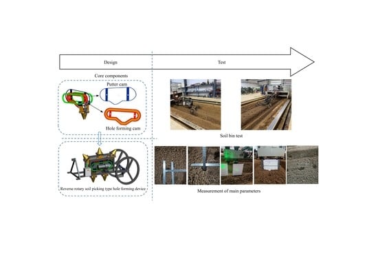
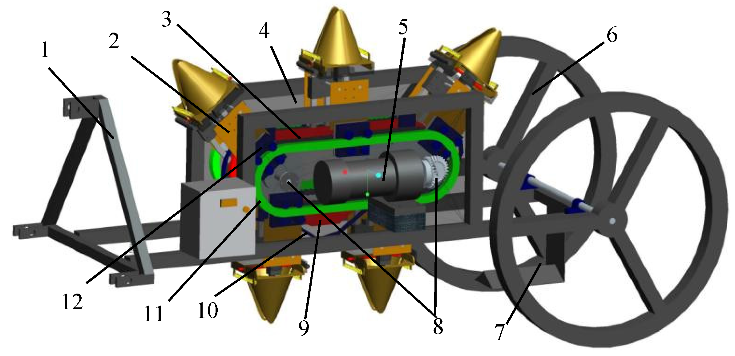
2.2. Overall Structure and Working Principle

The reverse-rotating soil-picking-type hole-forming device consisted of a hole-forming mechanism and a transmission system, the structure of which is shown in Figure 1. The main structure included a frame, a hole-forming mechanism (5 sets), a transmission system, a side plate (transparent in the 3D picture), a hole-forming cam and a putter cam. To be specific, the transmission system was largely composed of a chain and sprockets, a circular guideway, a slider, a motor, a transmission shaft, etc. The side plate was welded on the frame, the circular guideway was symmetrically fixed on the side plate and the slider was installed on the circular guideway. In addition, the hole-forming mechanism was fixed with the slider, capable of rotating around the circular guideway through the slider; the hole-forming cam and the putter cam were fixed in the frame through the transmission shaft. The retaining plate was installed inside the frame and in the same plane as the soil opener to prevent the taken soil from being thrown back into the formed hole.
When working, the soil bin tank pulled the hole-forming device at a uniform speed and the power of reverse rotation of the 5 sets of the hole-forming mechanism was inputted by the motor via the transmission shaft, the chains and sprocket and transmitted to the slider installed on the annular guide. Thus, the hole-forming mechanism fixed on the slider was driven to rotate and the linear speed of rotation of the hole-forming mechanism was equated with the forward speed of the hole-forming device. When the hole-forming mechanism entered the hole-forming stage, its speed was opposed to the forward speed of the whole machine and its size was equal. Thus, the hole-forming mechanism did not exhibit a horizontal speed relative to the soil surface at this stage. Then, under the joint action of the hole-forming cam and the putter cam, the soil opener in the hole-forming mechanism carried out the following actions: vertical soil inserting (with an open state of the soil opener); rotary soil taking (with a close state of the soil opener); vertical soil lifting (with a close state of the soil opener); and soil discharge and reset (the soil opener was first opened to the maximum angle to discharge soil and then reverted to the initial state). These operations were conducted according to the sequence as required by design, so as to form holes in the soil that met the design requirements. As shown in Figure 2, to intuitively understand the interaction between the key components of the hole-forming device, a three-dimensional schematic diagram of each working stage was drawn.

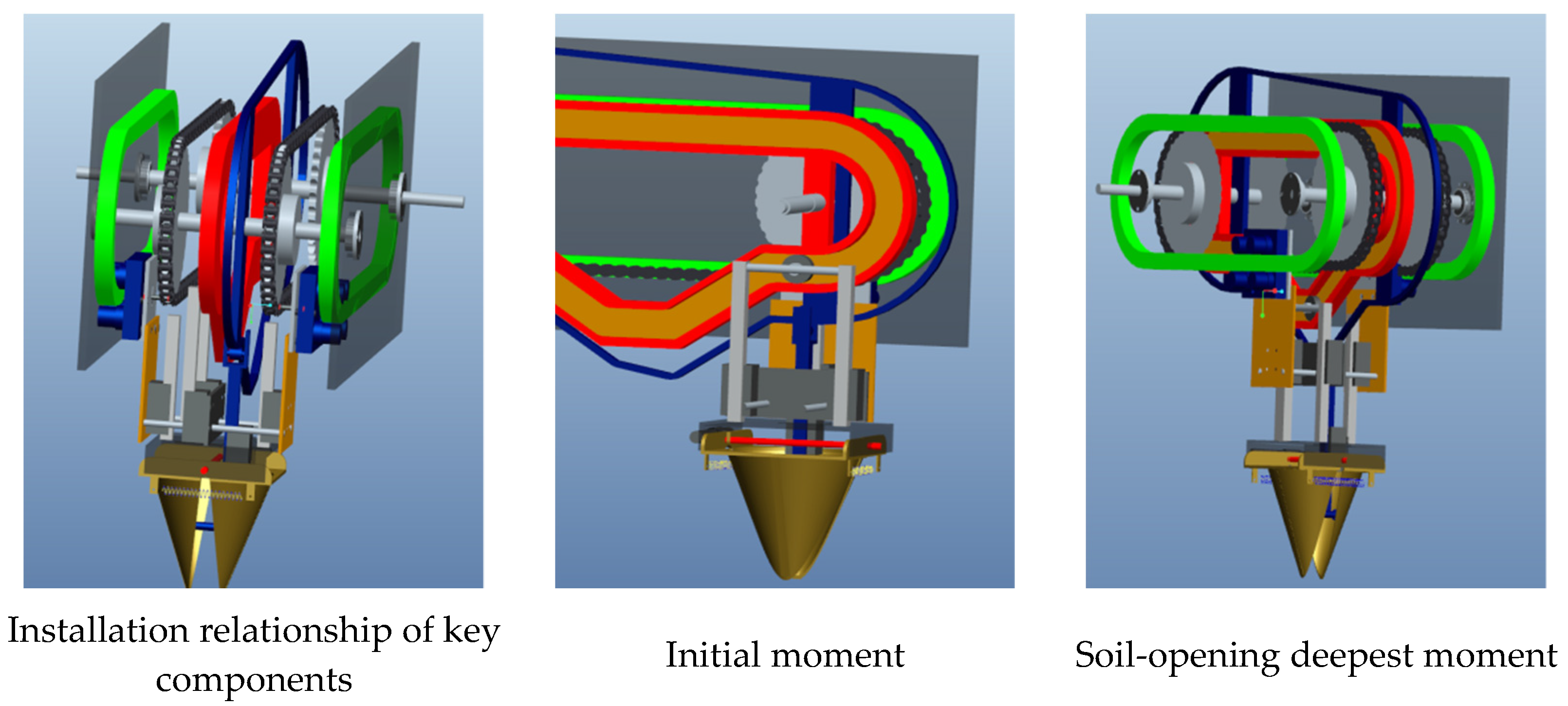
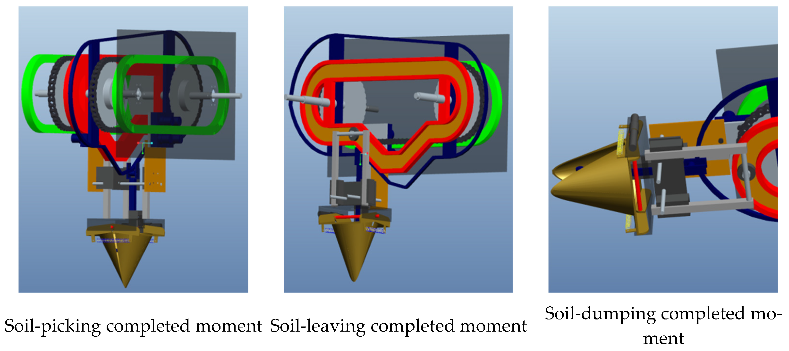
2.3. Design of the Hole-Forming Mechanism

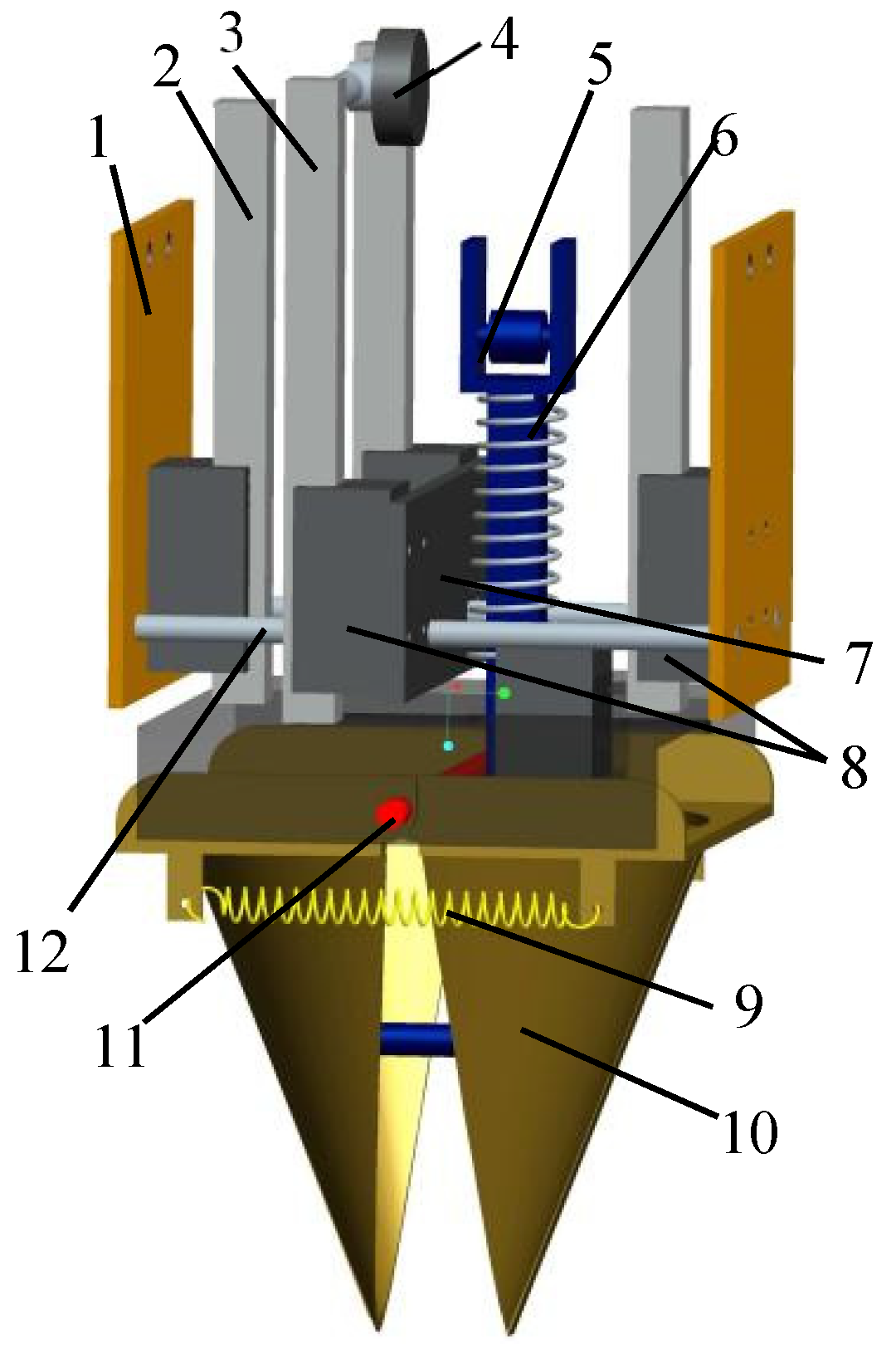
2.3.1. Overall Structure

The hole-forming mechanism studied in this paper was an important part of the reverse rotary soil-picking-type hole-forming device. It included a small side plate, a linear guide rail, a putter of open and close, a putter of bearing, a putter of hole forming, a putter spring, a support side plate, a return spring, a soil opener and a bracket of the soil opener. The structure is shown in Figure 3.
The small side plate was fixed on the slider and the support side plate was fixed on the small side plate by the support axis. The linear guide rail and the putter of hole forming were installed on four linear bearings, respectively, which could achieve up-and-down reciprocating motions. The upper end of the putter of hole forming was installed with a putter bearing that always moved in the hole-forming chute; the linear bearing was fixed on the small side plate and the support side plate, respectively, while the bottom end of the linear guide rail was welded on the soil-opener bracket. The soil opener was installed on the soil-opener bracket by the bracket axis, the putter of open and close, the return spring and the putter spring, which could rotate around the bracket axis. Among them, the putter of open and close was installed in the soil-opener bracket by linear bearing; its upper end was always in contact with the outer contour of the putter cam under the action of the putter spring and the return spring; the lower end was always in contact with the inner wall of the soil opener through the roller. The putter spring was set on the putter of open and close in a compression state and the return spring was hung on the soil opener in a stretching state. The up-and-down motions of the putter of open and close in the linear bearing could make the soil opener close and open.

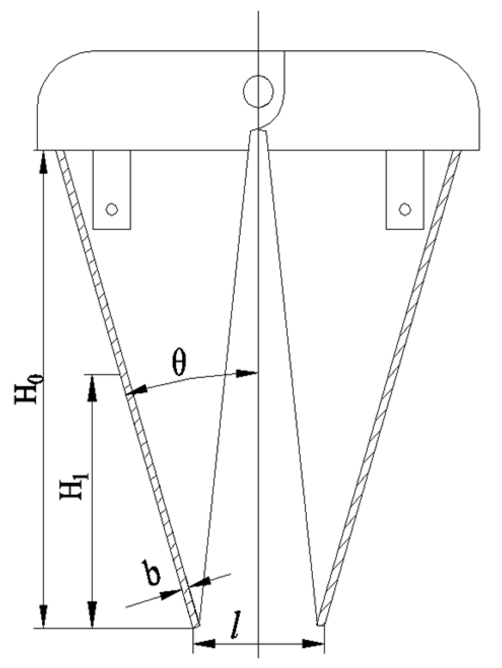
2.3.2. Design of Soil Opener

The soil opener was a vital part of the hole-forming mechanism and the soil opener formed the planting hole in the soil by inserting the soil, taking the soil and lifting the soil. In addition, the shape of the hole would directly affect the quality of pot seedling transplanting. Figure 4 presents the schematic diagram of the conical table soil-taking soil opener designed in this study. The soil opener acted as the soil-touching part of the hole-forming device, so the design of its parameters significantly affected the quality of the shape of the formed holes; the cutting-edge section thickness was considered a main parameter affecting the soil-cutting resistance. In general, the thinner the cutting-edge section thickness, the smaller the soil cutting resistance was, whereas the soil opener was prone to deform and even collapse. Thus, the cutting-edge section thickness b was selected as 2 mm [28,41].
According to the previous research results [40], the bottom size l of the soil opener was selected as 35 mm. In accordance with the requirements of planting depth and the structural characteristics of the hole-forming mechanism, the height H0 of the soil opener was selected as 150 mm. If the angle of entry θ was overly large, the resistance of entry increased and the porosity of the soil in the hole wall was reduced. If the angle of entry θ was excessively small, it was not conducive to the stability of the soil in the hole wall. Based on the existing research results, the angle of entry θ was selected as 17° [29].

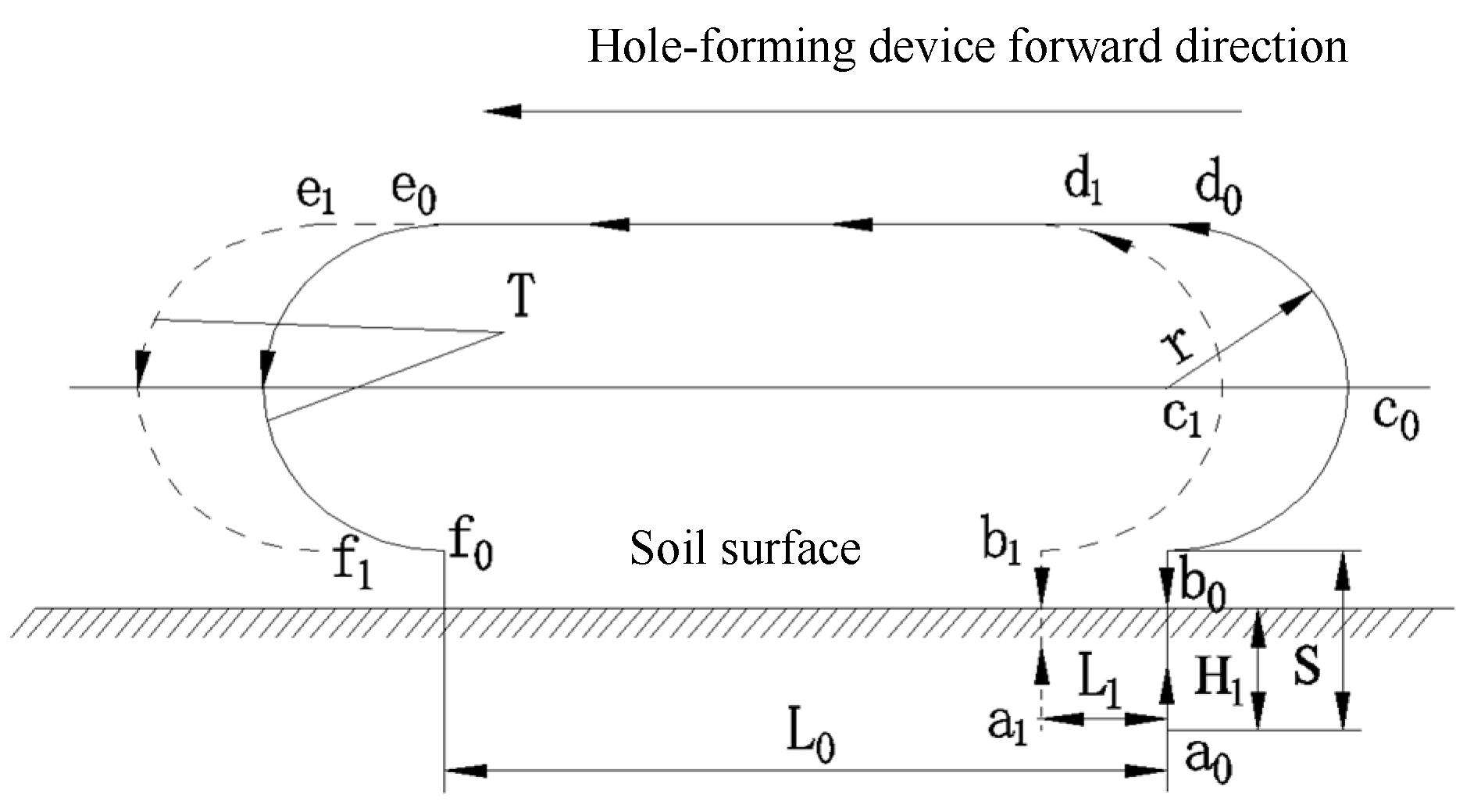
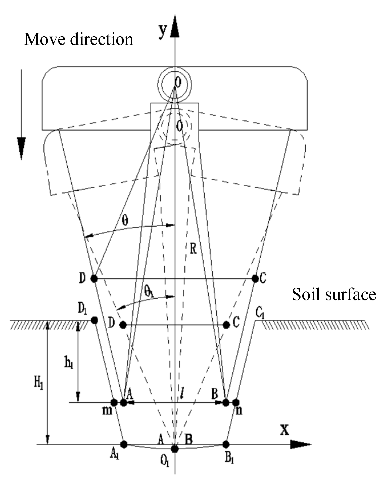
2.3.3. Movement Trajectory Analysis of Soil Opener

In this study, the movement trajectory of the soil opener comprised two parts, including the vertical inserting, vertical lifting and rotation process of the soil opener relative to the soil surface and the process of soil taking. Three-dimensional drawing software was applied for 3D modeling of the soil-forming device; the motion parameters of the respective component were defined in the mechanism of the application program and the linear speed of rotary motion of the soil opener was equal to the forward speed of the whole machine. The centers of the circle of the two adjacent shafts of the bracket of the soil opener were selected to track the trajectory (Figure 5). The movement track of a complete rotation consisting of b0–a0–b0–c0–d0–e0–f0 relative to the soil surface of the soil opener was determined and b1–a1–b1–c1–d1–e1–f1 was the movement track of the adjacent soil opener. To be specific, the corresponding sections b0a0 and a0b0 were found as the movement track of the soil opener in the soil-inserting and soil-lifting stage; the b0c0 section was found as the movement track of the soil discharging stage. The c0d0e0 and e0f0 sections were the track of the reset and return stage of the soil opener, respectively. The soil-opening depth H1 was 65 mm and the plant spacing L1 was 300 mm, thus meeting the requirements of rapeseed pot seedling planting.

2.3.4. Hole Contour and Shape Parametric Equations

The hole was formed by the interaction between the contour of the soil opener and the soil, thus confirming that the theoretical contour shape of the hole formed by the soil opener in the soil was the envelope of the movement track of the soil opener. According to Figure 6, the coordinate system of the soil-inserting and soil-taking process of the soil opener was built; the soil opener selected the O point as the center of the circle. After the maximum soil-inserting depth was reached, the soil opener rotated inward by a θ − θ1 angle for soil taking; the movement trajectories of points A, B, C and D constituted the theoretical contour of the hole; and the hole was represented by an envelope composed of D1-A1-O1-B1-C1. D1A1 and C1B1 were the movement trajectories of endpoints A and B and the movement trajectories of resistance surfaces DA and CB at the soil-inserting stage, while A1O1 and B1O1 were the movement trajectories formed by endpoints A and B at the soil-taking stage.
(1) The parameter equations of segment D1A1 and segment C1B1 of the hole side formed by the external contour of the soil opener contacting the soil at the vertical soil-inserting stage are written as
{ y D 1 A 1 = 1 2 tan θ ( 2 x + l ) y C 1 B 1 = 1 2 tan θ ( 2 x l ) H 1 tan θ l 2 x < l 2 l 2 x < H 1 tan θ + l 2
(2) At the soil-taking stage, A and B rotated around point O as the center of the circle till the soil opener was completely closed; the parameter equations of the bottom edges’ sections A1O1 and B1O1 of the hole are written as
{ y A 1 O 1 = R 2 x 2 + R 2 l 2 4 y B 1 O 1 = R 2 x 2 + R 2 l 2 4 l 2 x < 0 0 x < l 2
Since the formation of a hole is the result of the interaction between the external contour of the soil opener and the soil, the theoretical shape of the hole acts as the envelope of the movement track of the soil opener in the soil [21,22]. Through two sets of Equations (1) and (2), the contour of the hole can be expressed in two parts. In the process of soil inserting and soil taking, the contour of the hole consists of segments DA and CB and the movement track of special points A and B, thus forming the hole with a large upper end and a small lower end, which contributes to the stability of the hole. The coordinates of the respective point on the curve could be directly calculated from the parameter equation of hole contour, by calculating the coordinates of the respective point; the shape of the hole was described and parameterized, helping understand the main factors of the size of the hole. According to Figure 6, the intersection points between the straight line at an arbitrary depth from the soil surface h1 (h1 ≤ H1) on contour lines D1A1 and C1B1 and the hole contour line were assumed to be m and n, respectively. Since the beaks on the left- and right-hand sides of the soil opener were symmetrical about axis-y and were vertically inserted into soil, the hole top size at h1 could be defined as
l m n = x n x m = 2 x n = 2 ( H 1 h 1 ) tan θ + l
By analyzing the mentioned parameter (Equation (3)), it could be seen that the soil-opening depth H1, soil entry angle θ and bottom size of the soil opener l were the vital factors of the size of hole top and hole bottom.

2.4. Design of Putter Cam and Hole-Forming Cam

To keep the bottom size and middle size of soil opener unchanged during the soil-inserting and soil-lifting stages and to ensure that the actions of soil inserting, soil taking, soil lifting, soil discharge and reset of the soil opener were coordinated to the sequential design requirements, the hole-forming cam, the putter cam and its affiliated components were designed. As shown in Figure 7, the putter cam and hole-forming cam were fixed in the side plate of the frame through the transmission shaft. Impacted by the putter spring, the guide roller fixedly connected with the putter of open and close always kept in contact with the outer contour surface of the putter cam (connecting the line of points A3, B3, C3, D3, E3, F3, G3, H3, O and I3); the putter bearing installed on the hole-forming putter always moved in the inner groove of the hole-forming cam (the movement trajectory of the putter bearing center was the line connecting points A2, B2, C2, D2, E2, F2, G2, H2 and I2).
Line segments A3B3C3D3 and A2B2C2D2 refer to the hole-forming stage of the soil opener, where point A3 represents the initial position of the hole-forming stage and segment A2B2 refers to the soil-inserting stage of the soil opener. At this stage, the hole-forming putter moved down at a certain speed to drive the soil opener into the soil vertically. At the same time, the putter of open and close moved down at the same speed in segment A3B3 to ensure that the bottom end of the soil opener was always open in the process of soil inserting and the size of the bottom end remained unchanged. The segment B2C2 refers to the soil-collecting stage of the soil opener; relative to the soil surface, the horizontal and vertical velocities of the soil opener were zero at this stage (the soil opener had reached the maximum soil-inserting depth), the putter of open and close moved upward along the contour line of segment B3C3 and the soil opener rotated inward with the bracket axis as the rotation center to complete soil taking under the joint action of the putter of open and close, the return spring and the putter spring. The segment C2D2 refers to the soil-lifting stage of the soil opener and the segment C3D3 represents the movement track of the guide roller on the putter of open and close. At this stage, the hole-forming putter and the putter of open and close moved upward at the same speed to ensure that the soil opener always conducted vertical soil lifting in a closed state. The segment E3F3 refers to the soil discharge stage of the soil opener. At this stage, the soil opener did not produce soil inserting or soil lifting under the action of the contour of the groove in segment E2F2. Under the action of the external contour of segment E3F3, the putter of open and close moved along the direction of soil inserting to the maximum displacement, so that the soil opener rotated outward to the maximum angle with the bracket axis as the rotation center to complete soil discharge. The discharged soil was thrown onto the retaining plate under the action of the forward speed of the machine and the rotary speed of the soil opener, thus sliding to the periphery of the formed hole. Segments F3G3H3OI3A3 and F2G2H2I2A2 represent the movement tracks of the guide roller and the putter of hole forming in the return stage of the soil opener.

2.4.1. Parametric Equations of Putter Cam

Three-dimensional drawing software was adopted to express the movement track of the guide roller on the upper end of the putter of open and close of the soil opener; given the movement of the respective stage of the soil opener, the hole-forming mechanism was covered around the slewing guide, the center of the guide roller of the respective two putters of open and close was connected with a curve and the curve Ii formed was the central contour curve of the putter cam. Subsequently, the limit contour curve of the putter cam was generated in accordance with the size of the guide roller. The coordinate system was established (Figure 7). Axis-x coincides with the line between Point F3 and O and axis-y passes through the far-left end of the putter cam, tangent to the arc H3OA3. The abscissas of limit points A3, B3, C3, D3, E3 and G3 are expressed as x2~x6, respectively; that of F3 as x8; that of H3 and I3 as x1; and that of O as 0. The ordinates of limit points G3 and H3 are expressed as y1~y2; those of D3, E3, I3 and A3 as y5~y6; those of C3 and B3 as y8~y9; and those of O and F3 as 0, respectively. The interpolation method was adopted to work out the parameter equations of the respective step of the putter cam [19].
A3B3 step:
y = 75 107 x + 386 107 206 x < 313
B3C3 step:
y = 7 34 x 9773 68 313 x < 381
C3D3 step:
y = 75 107 x 50938 107 381 x < 488
D3E3F3 step:
{ y = 134 ( y 47 ) 2 + ( x 605 ) 2 = 180 2 488 x < 600 600 x < 779
F3G3H3 step:
{ y 2 + ( x 600 ) 2 = 179 2 y = 31 452 x + 62308 452 600 < x 779 148 < x 600
H3OI3A3 step:
{ y 2 + ( x 148 ) 2 = 148 2 y = 148 0 x 148 148 < x < 206

2.4.2. Parametric Equations of the Hole-Forming Cam

According to the coordinate system shown (Figure 7), the abscissas of limit points A2, B2, C2, D2, E2, F2 and G2 are expressed as x2~x7; and those of H2 and I2 as x1, respectively. The ordinates of limit points G2 and H2 as y3; I2, A2, D2 and E2 are expressed as y4; those of C2 and B2 as y7; and those of O and F2 as 0, respectively. The interpolation method was adopted to work out the parameter equations of the respective step of the putter cam [19].
A2B2 step:
y = 75 107 x + 6783 107 206 x < 313
B2C2 step:
y = 156 313 x < 381
C2D2 step:
y = 75 107 x 45267 107 381 x < 488
D2E2F2G2H2 step:
{ y = 81 y 2 + ( x 600 ) 2 = 81 2 y = 81 488 x < 600 600 x < 681 148 x < 600
H2I2A2 step:
{ y 2 + ( x 148 ) 2 = 81 2 y = 81 67 x < 148 148 x < 206
To ensure the rationality of the external contour curve of the putter cam and the inner groove curve of the hole-forming cam, the pressure angle between the putter of open and close and the putter cam at the hole-forming stage of the soil opener was examined. According to Figure 7, the putter of open and close in section B3C3 moved upward as it was impacted by the putter spring, so there was no self-locking phenomenon at this stage. According to the obtained contour parameter equation of the putter cam, the included angle between the section A3B3 of the contour curve of the putter cam and the horizontal direction, and the included angle between the section C3D3 of the contour curve of the putter cam and the horizontal direction were 35°. In other words, the pressure angle between the inner groove curve of the hole-forming cam and the putter of hole forming was 35° when the putter bearing moved in sections A2B2 and C2D2, which was within a reasonable range [42].

2.5. Number of the Hole-Forming Mechanism

In accordance with the requirements of rapeseed agronomy, the hole distance of pot seedlings was determined as 300 mm; n hole-forming mechanisms had an even distribution on the guide rail of the rotary system. In the hole-forming operation, there might be interference between two adjacent hole-forming mechanisms; thus, when the soil-lifting stage of the previous hole-forming mechanism was completed, the adjacent hole-forming mechanism had just entered the soil-inserting stage. In this design, the sprocket model was selected as 10A; based on the pitch of the corresponding chain, the number of the hole-forming mechanism n should satisfy the following equation:
{ L 1 = n 1 p n 2 L 1 = S 1 S 1 = π D + 2 L 2 L 2 L 1 + L 3
where L1 denotes the center distance between the respective hole-forming mechanisms, which is the distance between the formed holes (mm); n1 represents the number of chain pitches between the symmetrical centers of two adjacent hole-forming mechanisms; p expresses the chain pitch (mm); n2 represents the number of hole-forming mechanisms (number); S1 denotes the chain length (mm); D expresses the diameter of the sprocket graduation circle (mm); L2 represents the center distance between the two sprockets (mm); and L3 denotes the length of the slider (mm).
Since the slider should be in a horizontal position at the beginning of the hole-forming stage, the size of the slider was known as L3 = 100 mm, the center distance between the respective hole-forming mechanism was designed to be 300 mm and the diameter of the circular arc section of the annular guide rail and the sprocket indexing circle D was 192 mm. Since the hole-forming mechanism should have a uniform distribution on the annular guide rail, given Formula (15), n2 was 5, sprocket center distance L2 was 452.4 mm, chain length S1 was 1508 mm and n1 was 19.

2.6. Soil Bin Test Condition and Equipment

2.6.1. Test Condition and Equipment

To verify the accuracy of the mentioned design method and the reliability of the hole-forming device, a test bench of the hole-forming device was set for soil bin test, which was performed in the digital soil bin of the Agricultural Mechanization Engineering Training Center of Hunan Agricultural University (Figure 8). In general, the soil was clay loam. The testing equipment consisted of a soil trough tractor, a reverse rotary soil-picking-type hole-forming device, a laser pen (it was installed on the hole opener), a stopwatch (used to determine the frequency of hole forming), a firmness tester (used to determine soil firmness), an electronic scale, an aluminum box (used to determine soil water content and soil porosity), a steel ruler, a tape, a tool knife, a soil bulk density tester, a hole shape mapper, coordinate paper, etc.

2.6.2. Test Method

Before the test, the soil in the soil tank was compacted by the pressing roller, watered by the sprinkler system and tilled by the rotary cultivator. The soil water content at 0–150 mm reached 19.2% on average and soil firmness was 195 kPa. The hole-forming device moved forward at 0.25, 0.35 and 0.45 m/s under the traction of the soil bin car (the rotary linear velocity of the hole-forming mechanism was regulated to be equal to the forward velocity, so the frequency of hole forming was 50, 70 and 90 hole/min, satisfying the frequency requirements of rapeseed pot seedling transplanting); since the speed of the soil trough tractor was unstable during starting and stopping, the middle 15 m within 20 m of the operation of the soil trough tractor was taken as the test area for each test. The test was repeated for three times and data results were taken as the average values and parameters (e.g., hole-opening diameter, effective depth, hole distance, qualified number of holes, soil porosity of the hole wall and soil disturbance amount of the hole wall), determined for the respective tests.
(1) The shape and size of holes
As shown in Figure 9, the center distance of two adjacent holes was set as the hole distance. During the test, the center distance of all adjacent holes within 15 m was determined (l1, l2, l3) and the mean value was taken as the hole distance of this test. The size of the maximum distance was measured between two points on the contour line of the end face of the hole along the forward direction of the whole machine X1; the size of the maximum distance was measured between two points on the contour line of the hole face perpendicular to the forward direction of the whole machine Y1; (X1 + Y1)/2 expresses the average value of the two, which was taken as the hole opening diameter of a single hole. During the test, the opening diameter of all holes within 15 m was measured and the average value was adopted as the diameter of formed holes. Its vertical height (h) was measured as the effective depth along the upper-end face of the formed hole until the minimum end-face size within the hole was equal to 2 b2. During the test, the effective depth of all holes within 15 m was measured and the average value was adopted as the effective depth of the hole.
Qualified holes: If the hole opening diameter exceeded 2 a2 and the effective depth of the hole h was not less than the height of the pot seedling matrix c, the hole qualified. Based on the analysis and calculation of different parameters measured in the field, the performance parameters of the hole-forming device were obtained as follows: qualified rate of hole forming Q, change rate of hole size k [19].
Qualified rate of hole forming Q (%):
Q = N h g N × 100 %
In the equation, Nhg and N represent the number of qualifying holes and the actual number of formed holes within the measured distance, respectively.
Change rate of hole size k (%):
k = | D 0 d 0 | d 0 × 100 %
In the equation, D0 represents the hole-opening diameter of actual holes (mm) and d0 represents the hole opening diameter of theoretical holes (mm).
(2) Perpendicularity of hole-forming operation
The glass plate was vertically inserted into the soil bin in accordance with the forward direction of the machine and the coordinate paper was evenly attached to the glass plate, as shown in Figure 10. These two processes had the aim to ensure that the laser pen installed on the respective soil opener frame could be irradiated to the coordinate paper and leave a laser point when the corresponding hole-forming mechanism entered the hole-forming stage. The laser spot followed the inserting and lifting action of the soil opener to leave a movement track on the coordinate paper; after photographing the laser point’s movement track using the continuous capture function of SLR camera, we extracted the laser point’s contour from the shooting images using Photoshop software and processed its gray scale. Then, the coordinate values of the laser points in each shooting image were read using the coordinate paper and the obtained coordinate values were input into Excel software. The linear regression of each coordinate point was carried out and the fitting straight line of the movement track of the laser points was obtained, corresponding to the movement tracks of the inserting and lifting process of the soil opener; the angle between the two fitting straight lines and the horizontal coordinate axis could reflect the perpendicularity of the soil opener during the hole-forming process. The five sets of soil openers carried out the hole-forming operation at different forward speeds and the hole-forming operation was repeated three times. The perpendicularity of the hole-forming operation of each set of soil openers was measured and the average value was taken.
(3) The soil porosity of the hole wall and soil disturbance amount
The soil porosity of the hole wall of the formed hole was measured using a self-made soil bulk density tester [29]. The bulk density tester consisted of a pressing handle and a self-made rectangular ring knife; the length, width and height of the inner cavity of the rectangular ring knife were 60 × 40 × 20 mm, as shown in Figure 11a. After the completion of the hole-forming operation, the surveyor pressed the soil bulk density tester down into the soil (the soil within 20 mm perpendicular to the direction of the hole wall) along the hole wall of the formed hole until the soil overflowed on the upper-end face of the rectangular ring knife; then, the excess soil on the upper and lower ends of the rectangular ring knife was cut with a tool knife and the soil in the ring knife was put into an aluminum box. The soil bulk density was calculated according to ρb = m/v, where m is the mass of dried soil in the aluminum box (g) and v is the volume of soil in the rectangular ring knife, that is, the volume of the rectangular ring knife inside the cavity (cm3). Then, the soil porosity of the hole wall was calculated by the soil porosity calculation formula.
ε = ( 1 ρ b / ρ s ) × 100 %
In the equation, ε is the soil porosity of the hole wall (%); ρb is the soil bulk density (g/cm3); and ρs is the soil density (g/cm3).
According to the soil disturbance contour measurement method [43,44], the mapping process is shown in Figure 11b. The hole shape mapper was composed of a base, a paper rod and a coordinate paper and its length, width and height were 400 × 100 × 300 mm. The diameter of the paper rod was 4 mm, the length was 250 mm, the paper bars were arranged adjacent to each other and a coordinate paper with a square-edge length of 1 mm was fixed on the hole shape mapper to map the soil disturbance contour after the hole was formed. After the completion of the hole-forming operation, the hole shape mapper was placed right above the hole; the plane of the coordinate paper coincided with the center section of the hole and the paper rod slid downward under the action of gravity until its bottom contacted the soil. At this time, the top end of the paper rod formed the contour curve of the hole section and the soil surface on the coordinate paper and the position of the top end of the paper rod on the coordinate paper was marked by a marker. The coordinates of each marker point were read and the synthetic curve was fitted, which was the contour section curve of the inner wall of the hole.
The soil heave degree of the hole mouth and soil stability rate of the hole wall were taken as the evaluation indexes of the soil disturbance amount and their calculation formulas can be written as follows:
P = A L A A   ×   100 %
δ = A h A   ×   100 %
where P denotes the soil heave degree of the hole mouth (the smaller the p-value, the lower the soil heave degree of the hole mouth) (%); A and AL are the cross-sectional areas from the soil surface to the theoretical hole bottom before and after the hole forming, respectively (mm2); δ is the soil stability rate of the hole wall (the greater δ, the closer the cross-section area of the actual hole to the theoretical hole, the less the soil returned in the hole) (%); and Ah is the cross-sectional area from the soil surface to the actual hole bottom after the hole forming (mm2). A was determined by the relevant parameters of the soil opener and AL and Ah could be calculated by MATLAB software.

3. Results and Discussion

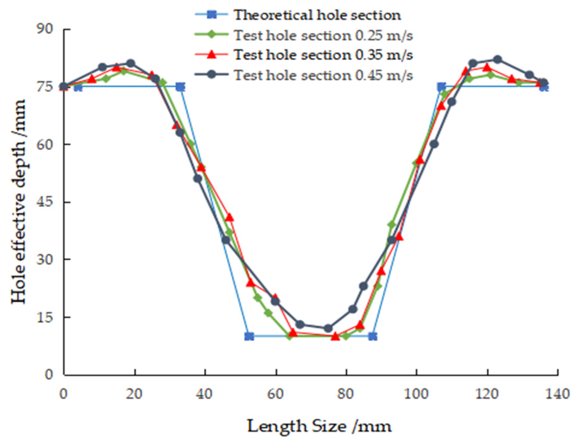
3.1. Analysis of Hole Size and Hole-Forming Quality

Table 2 shows the hole size and hole performance test results of the reverse-rotating soil-taking-type hole-forming device.
According to Table 2, when the forward velocities were 0.25, 0.35 and 0.45 m/s, the average values of the hole spacing of the adjacent two holes were 300.2, 299.1 and 298.3 mm, respectively, which met the design requirements. The change range of hole spacing at different forward speeds was small; the hole spacing was less affected by the forward speed and the slip rate had a slight effect on the hole-forming effect during the whole machine operation. When the forward speed increased from 0.25 m/s to 0.45 m/s, the average hole diameter was 75.7 mm, 76.2 mm and 78.1 mm, respectively, and the average change rates of hole size were 2.3%, 2.9% and 5.5%, respectively, thus indicating that the hole size at different speeds was not significantly different from the theoretical hole size. There was little clay in the closed soil-taking and vertical soil-lifting period of the soil opener and there was no soil scraping phenomenon in the rotation movement. However, with the increase in the forward speed, the change rate of the hole size tended to increase, thus indicating that the faster the speed of the machine (the faster the speed of the soil opener to insert in the soil, take the soil and lift the soil), the more obvious the extrusion and scraping of the soil during the hole-forming operation, which resulted in the collapse of a small part of the soil in the hole wall and the increase in the hole size. The average effective depths of each hole measured in the experiment at different forward speeds were 49.0 mm, 48.7 mm and 47.2 mm, respectively. The average error between the theoretical value of the effective depth and the experimental value was 2.0%, 2.6% and 5.6%, respectively. The above results were achieved because a small part of soil returned to the formed hole during the hole-forming process; the faster the forward speed was, the greater the error between the theoretical value and the experimental value of the effective depth and the more the soil reflux in the hole. Through the measurement and calculation of each test, it was concluded that when the forward speed was between 0.25 m/s and 0.45 m/s, the average qualified rate of forming holes was between 93.3% and 95.2%, indicating that the working stability of the whole machine was high and met the design requirements.

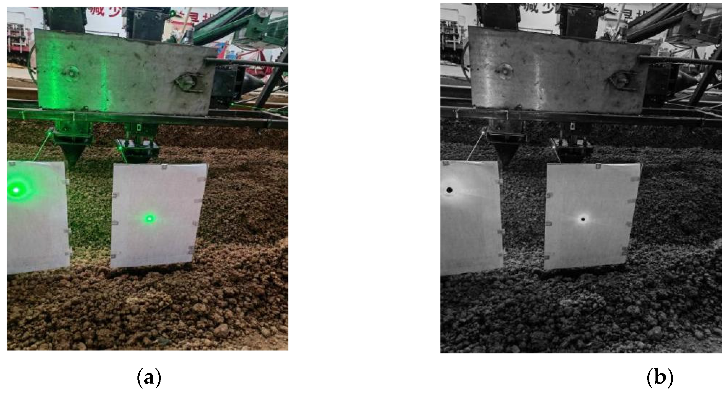
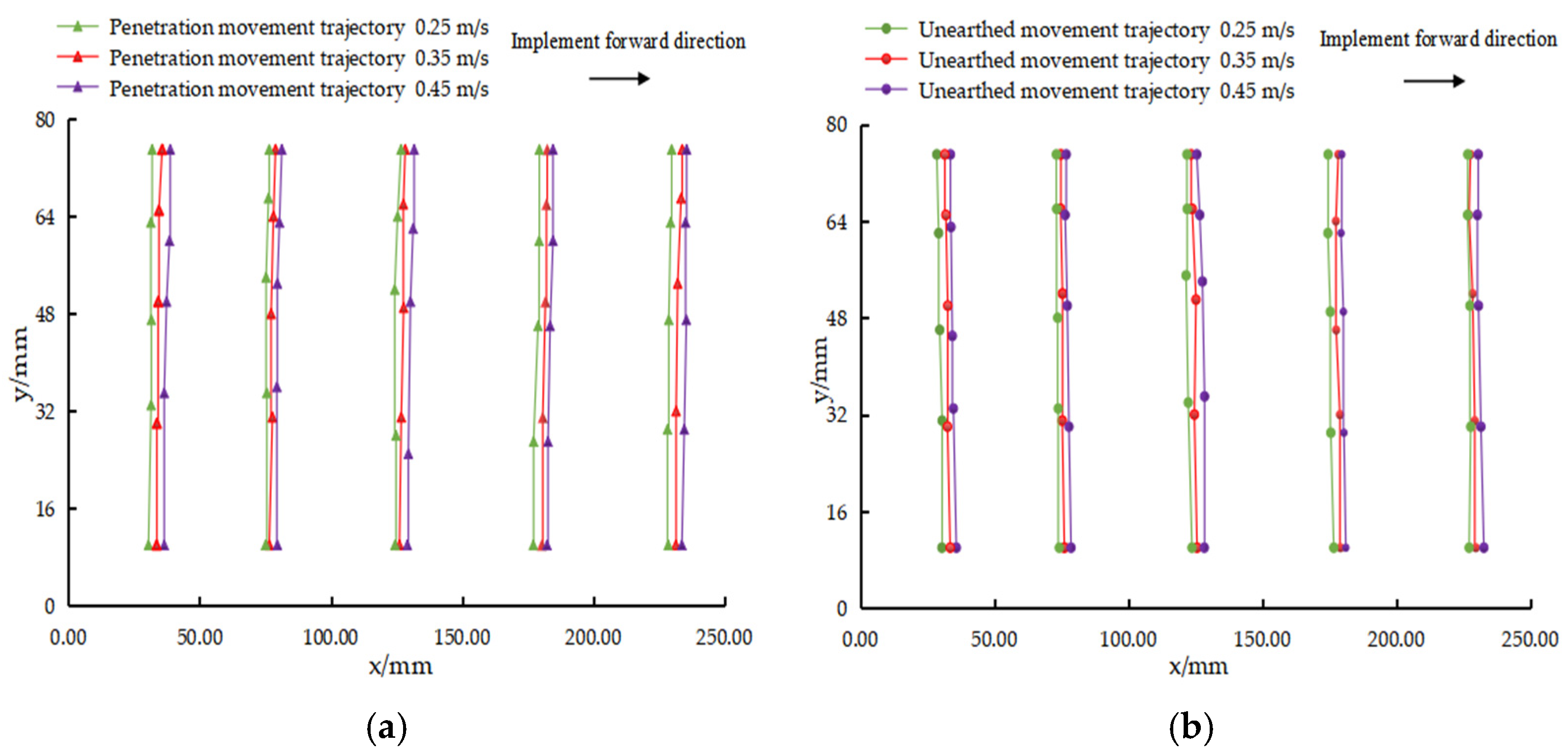
3.2. Results and Analysis of Perpendicularity of Hole-Forming Operation

In the process of the hole-forming experiment, the laser point images of one set of soil opener taken by the SLR camera are shown in Figure 10. After the hole-forming operation was completed, all the images were extracted and the gray scale was processed; the coordinate values of the laser points on the coordinate paper in each group of images were read and the linear regression of each point was conducted. The results are shown in Figure 12.
Figure 12 shows that the soil-inserting trajectory and the soil-lifting trajectory under different velocity conditions were basically vertical. It can be seen from Figure 12a,b that the angle between the soil-inserting trajectory of the soil opener and the x-axis was slightly less than 90° and the angle between the soil-lifting trajectory of the soil opener and the x-axis was slightly larger than 90°. When the hole-forming operation was carried out, the soil-inserting trajectory and the soil-lifting trajectory showed a “V”-type trend, indicating that, in the operation stage, the actual forward speed of the whole machine was slightly smaller than the rotary linear speed of the hole-forming mechanism. It can be seen from Table 3 that, when the forward speed of the machine was 0.25 m/s, 0.35 m/s and 0.45 m/s, respectively, the average angle between the trajectory of the soil opener during the soil-inserting stage and the horizontal direction was 88.4°, 88.0°and 88.1°, respectively, and the variation coefficients were 0.53, 0.16 and 0.40, respectively. The average angle between the trajectory of the soil opener during the soil-lifting stage and the horizontal direction was 88.7°, 88.5° and 88.1°, respectively, and the variation coefficients were 0.64, 0.54 and 0.47, respectively. The minimum value of the angle between the motion trajectory of the soil opener and the horizontal direction was higher than 88°, indicating that the perpendicularity of the soil opener during soil inserting and soil lifting was high under the actual working conditions [23]. The forward speed of the machine did not affect the perpendicularity of the hole-forming operation and the soil opener met the design requirements of the vertical soil inserting and lifting.

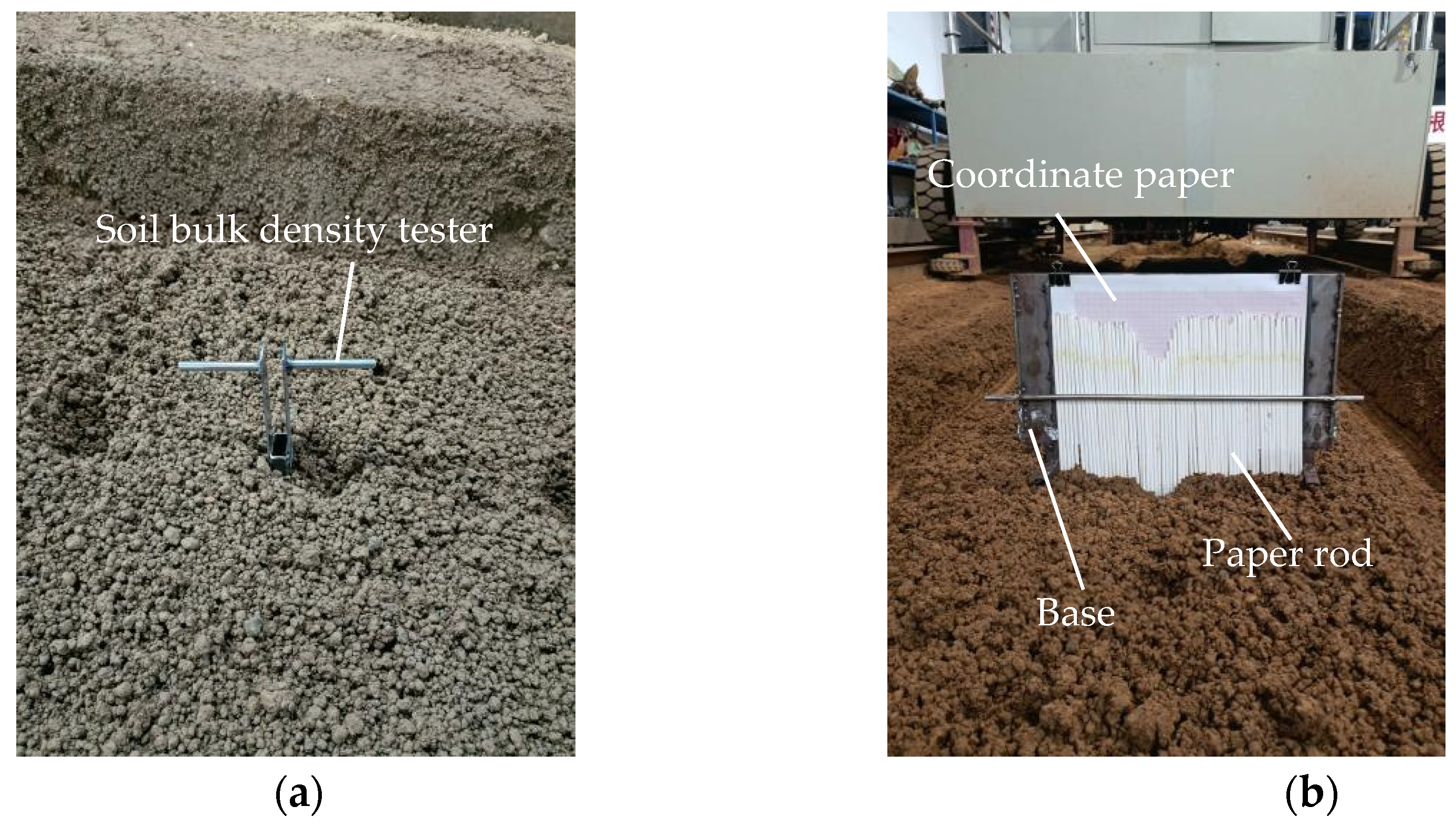
3.3. Analysis of the Soil Porosity of the Hole Wall and Soil Disturbance Effect

The contour of the soil disturbance hole shape section after the hole-forming operation at three forward speeds is shown in Figure 13. According to Formula (18), the soil porosity of the hole wall before and after hole-forming operation was calculated. According to the soil disturbance contour (Figure 13) and Equations (19) and (20), the soil heave degree of the hole mouth and the soil disturbance amount were calculated; the results are shown in Table 4.
Table 4 shows that, when the forward speeds were 0.25 m/s, 0.35 m/s and 0.45 m/s, the average soil porosity of the hole wall after the completion of the hole-forming operation was 48.4%, 48.3% and 47.8%, respectively; compared with before the hole-forming operation, the average change rates of soil porosity were 8.2%, 9.3% and 8.9%, respectively. With the increase in the forward speed, the soil porosity of the hole wall showed a downward trend. Although the soil porosity decreased, the change rate was not large and the soil porosity of the hole wall was within the range of agronomic requirements, which would not affect the growth of crops [45]. After the hole-forming operation, the mean soil heave degree of the hole mouth was 3.9%, 4.1% and 4.2% and the average soil stability rate of the hole wall was 91.9%, 91.2% and 91.0%, respectively. At different forward speeds, the soil around the formed hole was of low heave degree under the extrusion effect of the soil opener and the contour section of the actual formed hole was slightly different from the theoretical one. At the same time, it was also found that there was an insignificant difference in the soil porosity of the hole wall of the hole formed by the hole-forming device designed in this paper before and after the hole-forming operation and the hole-forming device had slight disturbance to the soil during the hole-forming operation.

4. Conclusions

1. A type of reverse-rotating soil-taking-type hole-forming device of pot seedling transplanting machine for rapeseed was designed based on the working characteristics of the hole-punching transplanter and the agronomy requirements of rapeseed transplanting. In this study, the design scheme of a reverse-rotating hole-forming mechanism is proposed. At the hole-forming stage, the vertical soil-inserting and -lifting actions of the soil opener were achieved by providing the speed equal to the forward speed of the whole machine and in the opposite direction; then, a series of holes were formed in the soil by combining the soil-taking and soil-discharging actions of the soil opener.
2. A hole-forming device test bench was built for the soil bin tests at different forward speeds. It was found from the test results that, when the hole-forming device advanced at the speeds of 0.25 m/s, 0.35 m/s and 0.45 m/s, the average qualified rates of hole forming of the device were 95.2%, 94.0% and 93.3% and the average change rates of the hole size were 2.3%, 2.9% and 5.5%, respectively. The average error between the theoretical value of effective depth and the experimental value was 2.0%, 2.6% and 5.6%. The average value of the angle between the trajectory of the soil opener at the hole-forming stage and the horizontal direction was between 88.0° and 88.7° and the variation coefficient was between 0.16% and 0.64%; the perpendicularity of the hole-forming operation was high. At different forward speeds, the average soil porosity of the hole wall after the completion of the hole-forming operation was 48.4%, 48.3% and 47.8%, respectively, while the change rates of soil porosity were 8.2%, 9.3% and 8.9%, respectively, compared with those before the hole-forming operation. The average soil heave degree at the hole mouth after the completion of the hole-forming operation was 3.9%, 4.1% and 4.2%, respectively, and the average soil stability rate of the hole wall was 91.9%, 91.2% and 91.0%, respectively.
3. In this paper, rapeseed seedlings could still have better verticality after being transplanted, so the soil porosity around the pot seedling was still high after operation, thus leading to high air permeability and water permeability for the growth of the pot seedlings. In subsequent research, the power transmission mode should be changed, the power of the rotary movement of the hole-forming mechanism should be inputted by the power output shaft of the tractor via the gearbox. In the future, a supporting mechanical seedling feeding device should be introduced to solve the problem whereby the machine can only achieve mechanical hole forming and then seedlings need to be fed manually. During the operation of hole forming, the change in the working parameters of the soil opener (e.g., the bottom size, soil entry angle, soil entry depth and soil entry speed of the soil opener) have effects on soil disturbance. At a subsequent stage, the above factors resulting in soil disturbance will be investigated in depth. Furthermore, the working parameters of the soil opener will be optimized to improve the qualified rate and quality of the hole.

5. Patents

Three patents have been applied for in China for Hole-Forming Device of Pot Seedling Transplanting Machine for Rapeseed in this manuscript (Patent No. ZL201910984983.X and Application Nos. CN202110794519.1, CN202110794523.8).

Author Contributions

Conceptualization, W.Q., M.W. and H.L.; methodology, W.Q.; software, W.Q. and Z.D.; validation, W.Q., M.W., Z.D., H.L. and F.S.; formal analysis, W.Q.; investigation, W.Q., Z.D. and F.S.; resources, W.Q.; data curation, W.Q.; writing—original draft preparation, W.Q.; writing—review and editing, W.Q. and M.W.; visualization, W.Q.; supervision, M.W.; project administration, M.W.; funding acquisition, M.W. and H.L. All authors have read and agreed to the published version of the manuscript.

Funding

This research study was funded by Natural Science Foundation of Hunan Province, China (No. 2021JJ30344 and 2020JJ5254) and Key Projects of Hunan Provincial Science and Technology Department (No. 2019NK2151).

Institutional Review Board Statement

Not applicable.

Informed Consent Statement

Not applicable.

Data Availability Statement

The datasets used and/or analyzed during the current study are available from the corresponding author on reasonable request.

Acknowledgments

The authors would like to thank their schools and colleges, as well as the funding providers of the project. All support and assistance are sincerely appreciated.

Conflicts of Interest

The authors declare no conflict of interest.

Nomenclature

b—Cutting-edge section thickness (mm).l—Bottom size of soil opener (mm).
H0—Height of soil opener (mm).θ—Angle of entry (°).
H1—Soil-opening depth (mm).L1—Center distance between two adjacent soil opener (mm).
h1—Arbitrary depth from the soil surface (mm).lmn—Hole top size at h1 (mm).
n1—Number of chain pitches between the symmetrical centers of two adjacent hole-forming mechanisms.p—Chain pitch (mm).
n2—Number of hole-forming mechanisms.S1—Chain length (mm).
D—Diameter of sprocket graduation circle (mm).L2—Center distance between the two sprockets (mm).
L3—Length of slider (mm).a2—Side length of upper end face (mm).
l1/l2/l3—Center distance between adjacent holes (mm).b2—Side length of lower end face (mm).
X1—Points on the contour line of the end face of the hole along the forward direction of the whole machine (mm).c—Height of the pot seedling matrix (mm).
Y1—Two points on the contour line of the hole face perpendicular to the forward direction of the whole machine (mm).h—Effective depth of hole (mm).
Q—Qualified rate of hole forming (%).Nhg—Number of qualified holes.
N—Actual number of formed holes. k—Change rate of hole size (%).
D0—Hole opening diameter of actual holes (mm);d0—Hole opening diameter of theoretical holes (mm);
ε—Soil porosity of hole wall (%).ρb—Soil bulk density (g/cm3).
ρs—Soil density (g/cm3).P—Soil heave degree of hole mouth.
A—Cross-sectional area from the soil surface to the theoretical hole bottom before hole forming (%).AL—Cross-sectional area from the soil surface to the theoretical hole bottom after the hole forming (%).
δ—Soil stability rate of hole wall (%). Ah—Cross-sectional area from the soil surface to the actual hole bottom after the hole forming (mm2).

References

  1. Jarecki, W. The Reaction of Winter Oilseed Rape to Different Foliar Fertilization with Macro- and Micronutrients. Agriculture 2021, 11, 515. [Google Scholar] [CrossRef]
  2. Wei, H.; Jun, L.; Xiaomei, W.; Qiao, L.; Xiaowei, Y. Current status of global rapeseed industry and problems, countermeasures of China’s rapeseed industry. China Oils Fats 2021, 1–8. [Google Scholar]
  3. Yin, Y.; Yin, L.; Zhang, X.; Guo, J.; Wang, J. Status and Countermeasure of the High-quality Development of Rapeseed Industry in China. J. Agric. Sci. Technol.-Iran 2021, 23, 1–7. [Google Scholar]
  4. Can, M.; Haifeng, L.; Yi, Z.; Beibei, Z.; Xiao, X. Research status and development trend of seeding transplanting machinery. J. Chin. Agric. Mech. 2020, 41, 215–222. [Google Scholar]
  5. Wang, X.; Huang, M. Application of rape planting mechanization technology model in rice stubble field. Hubei Agric. Mech. 2020, 3–4. [Google Scholar] [CrossRef]
  6. Mengyuan, C. Problems and Countermeasures of developing rape planting mechanization. Jiangxi Agric. 2020, 104. [Google Scholar]
  7. Yongtao, L.; Yaxiong, L.; Yang, L.; Bing, L.; Tao, W. Status analysis of abroad’s transplanting machine and transplanting technology. Xinjiang Agric. Mech. 2011, 3, 29–32. [Google Scholar]
  8. Qiming, P. Current situation and development trend of domestic and foreign transplanting machine technology. J. Anhui Agric. Sci. 2013, 41, 12478–12479. [Google Scholar]
  9. Chunyun, G. The development trend of China’s rape industry. Grain Sci. Technol. Econ. 2011, 36, 5–6. [Google Scholar]
  10. Jin, X.; Du, X.W.; Geng, G.S.; Ji, J.T.; Dong, X.; Liu, W.X. Experiment on Planting System of 2ZDJ-2 Transplanter. Trans. Chin. Soc. Agric. Mach. 2015, 46, 26–31. [Google Scholar]
  11. Xiaoxu, Y.; Yun, Z.; Baocheng, C.; Maile, Z.; Hao, Z.; Zhichao, Z. Current situation and prospect of transplanter. Trans. Chin. Soc. Agric. Mach. 2014, 45, 44–53. [Google Scholar]
  12. Subo, T.; Lichun, Q.; Naoshi, K.; Ting, Y. Development of Automatic Transplanter for Plug Seedling. IFAC Proc. Vol. 2010, 43, 79–82. [Google Scholar]
  13. Felezi, M.E.; Vahabi, S.; Nariman-Zadeh, N. Pareto optimal design of reconfigurable rice seedling transplanting mechanisms using multi-objective genetic algorithm. Neural Comput. Appl. 2016, 27, 1907–1916. [Google Scholar] [CrossRef]
  14. Nandede, B.M.; Raheman, H. Multi-Stage Metering Mechanism for Transplanting of Vegetable Seedlings in Paper Pots. J. Inst. Eng. Ser. A 2015, 96, 295–300. [Google Scholar] [CrossRef]
  15. Dihingia, P.C.; Prasanna, K.G.V.; Sarma, P.K. Development of a Hopper-Type Planting Device for a Walk-Behind Hand-Tractor-Powered Vegetable Transplanter. J. Biosyst. Eng. 2016, 41, 21–33. [Google Scholar] [CrossRef] [Green Version]
  16. Chandra, S.; Kumar, S.; Kumar, V. Comparative Performance Evaluation of Self Propelled Paddy Transplanters in Calcareous Soil. AMA Agric. Mech. Asia Afr. Lat. Am. 2013, 44, 33–38. [Google Scholar]
  17. Selvan, M.M.; Annamalai, S.J.K.; Thavaprakash, N.; Ananathakrishnan, D. Design and development of three-row improved pull-type rice transplanter for small farmers. Indian J. Agric. Sci. 2014, 84, 1422–1427. [Google Scholar]
  18. Wei, X. Experiment Study on Planting Hole Forming Device of Transplanting Machine for Rape. Master’s Thesis, Hunan Agriculture University, Changsha, China, 2014. [Google Scholar]
  19. Xiang, W.; Mingliang, W.; Chunyun, G. Design and experiment of planting hole forming device of crawler transplanter for rape (Brassica napus) seedlings. Trans. Chin. Soc. Agric. Eng. 2015, 31, 12–18. [Google Scholar]
  20. Chaopeng, C.; Wei, Q.; Mingliang, W.; Wentao, Z. Parameter optimization of vertical soil-filling hole-forming parts for rapeseed transplantation based on discrete element method. J. Hunan Agric. Univ. Nat. Sci. 2019, 45, 433–439. [Google Scholar]
  21. Changjie, H.; Yang, X.; Jia, Y.; Jing, Z.; Panpan, Y. Parameter optimization of opener of semi-automatic transplanter for watermelon seedlings raised on compression substrate. Trans. Chin. Soc. Agric. Eng. 2019, 35, 48–56. [Google Scholar]
  22. Wei, X.; Mingliang, W.; Chunyun, G.; Yiming, H.; Haifeng, L.; Bo, Y. Design and Test of Transplanting Hole-forming Machine for Rapeseed Potted Seedlings. Trans. Chin. Soc. Agric. Mach. 2017, 48, 40–48. [Google Scholar]
  23. Zhang, Y.L.H.H. Design and experiment on rear suspended passive aerator in saline-alkali land. Trans. Chin. Soc. Agric. Eng. 2016, 32. [Google Scholar]
  24. Maile, Z.; Xianglei, X.; Mengbo, Q.; Daqing, Y. Optimal Design and Experiment of Potted Vegetable Seedling Transplanting Mechanism with Punching Hole. Trans. Chin. Soc. Agric. Mach. 2020, 51, 77–83. [Google Scholar]
  25. Wei, S.; Xiaolong, L.; Hucun, W.; Hua, Z.; Jianmin, W.; Xiaoping, Y.; Guanping, W. Design and test of double crank multi-rod hill-drop potato planter on plastic film. Trans. Chin. Soc. Agric. Eng. 2018, 34, 34–42. [Google Scholar]
  26. Rasool, K.; Islam, N.; Ali, M.; Jang, B.E.; Kwon, H.J. Onion transplanting mechanisms: A review. Precis. Agric. Sci. Technol. 2020, 2, 196. [Google Scholar]
  27. Chen, Y.; Cheng, Y.; Chen, J.; Zheng, Z.; Hu, C.; Cao, J. Design and Experiment of the Buckwheat Hill-Drop Planter Hole Forming Device. Agriculture 2021, 11, 1085. [Google Scholar] [CrossRef]
  28. Changjie, H.; Yang, X.; Jing, Z.; Jia, Y.; Hui, G. Design and experiment of semi-automatic transplanter for watermelon seedlings raised on compression substrate. Trans. Chin. Soc. Agric. Eng. 2018, 34, 54–61. [Google Scholar]
  29. Wei, Q.; Mingliang, W.; Haifeng, L.; Chaopeng, C.; Wei, X. Optimization of soil hole opening method and parameters of pot seedling transplanting machine for rapeseed. Trans. Chin. Soc. Agric. Eng. 2020, 36, 13–21. [Google Scholar]
  30. Lihua, Y.; Changshou, H.; Zhibo, X.; Fugui, Z.; Delong, F. Design and Test of Spiral Cavitation Device for Transplanting in Large Den. J. Agric. Mech. Res. 2020, 42, 198–202. [Google Scholar]
  31. Chen, J.W.B.Z. Kinematics modeling and characteristic analysis of multi-linkage transplanting mechanism of pot seeding transplanter with zero speed. Trans. Chin. Soc. Agric. Eng. 2011, 27, 7–12. [Google Scholar]
  32. Wang, Y.H.Z.W. Experiment on transplanting performance of automatic vegetable pot seedling transplanter for dry land. Trans. Chin. Soc. Agric. Eng. 2018, 34, 19–25. [Google Scholar]
  33. Xin, J.; Jiangtao, J.; Weixiang, L.; Yakai, H.; Du, X. Structural optimization of duckbilled transplanter based on dynamic model of pot seedling movement. Trans. Chin. Soc. Agric. Eng. 2018, 34, 58–67. [Google Scholar]
  34. Zhou, Y.; Chaohai, C.; Jieli, D.; Guoqi, Y.; Xuewen, P.; Liangli, Y.; Jialong, L. Performance test of hand-held electric hole-digger for fertilization in orchard. Trans. Chin. Soc. Agric. Eng. 2013, 29, 25–31. [Google Scholar]
  35. Orzech, K.; Wanic, M.; Załuski, D. The Effects of Soil Compaction and Different Tillage Systems on the Bulk Density and Moisture Content of Soil and the Yields of Winter Oilseed Rape and Cereals. Agriculture 2021, 11, 666. [Google Scholar] [CrossRef]
  36. Hu, H.L.H.W. Design and experiment of targeted hole-pricking and deep-application fertilizer applicator between corn rows. Trans. Chin. Soc. Agric. Eng. 2016, 32, 26–35. [Google Scholar]
  37. Jinwu, W.; Wenqi, Z.; Chunfeng, Z.; Zhenwei, P.; Jinfeng, W.; Han, T. Reverse Design and Experiment of Non-circular Gear Planetary System Picking Hole Mechanism. Trans. Chin. Soc. Agric. Eng. 2015, 46, 70–75. [Google Scholar]
  38. Mingliang, W.; Bo, Y.; Shijie, F.; Wentao, Z. Design of movable tray for bowl seedlings. J. Hunan Agric. Univ. Nat. Sci. 2018, 44, 666–671. [Google Scholar]
  39. Honglin, C.; Shanghong, C.; Xueshan, S.; Liangcai, J.; Dinghui, L. Effects of Different Density to the Agronomic Traits and Yield of Transplanting Rapeseed in the Hilly Area of Sichuan Basin. Chin. Agric. Sci. Bull. 2012, 28, 142–145. [Google Scholar]
  40. Wei, Q.; Mingliang, W.; Chunyun, G.; Haifeng, L. Experimental Study on the Shape Optimization of Soil Opener for Rapeseed Pot Seedling Transplanter. J. Agrc. Sci. Technol.-Iran 2021, 23, 97–106. [Google Scholar]
  41. Xueqing, Z.; Hongwen, L.; Jin, H.; Qingjie, W.; Xirui, Z. Design of multi-segment in situ soil sampler testing bulk density. Trans. Chin. Soc. Agric. Eng. 2008, 127–130. [Google Scholar] [CrossRef]
  42. Zhengxing, L. Fundamentals of Mechanical Design; Chongqing University Press: Chongqing, China, 2016. [Google Scholar]
  43. Chengguang, H.; Xijie, G.; Mengchan, Y.; Yuxiang, H.; Ruixiang, Z. Discrete element simulations and experiments of soil disturbance as affected by the tine spacing of subsoiler. Biosyst. Eng. 2018, 168, 73–82. [Google Scholar]
  44. Yuxiang, H.; Chengguang, H.; Mengchan, Y.; Botao, W.; Ruixiang, Z. Discrete Element Simulation and Experiment on Disturbance Behavior of Subsoiling. Trans. Chin. Soc. Agric. Eng. 2016, 47, 80–88. [Google Scholar]
  45. Wei, Y.; Liang, G.Z.; Feng, B. Effect of Plants at Different Fertilization Treatments on Soil Bulk Density and Porosity in the Gully Region of Loess Plateau. Shaanxi For. Sci. Technol. 2014, 1–5. [Google Scholar] [CrossRef]
Figure 1. Structure diagram of reverse rotary soil-picking-type hole-forming device: 1—frame; 2—hole-forming mechanism; 3—chain and sprockets; 4—side plate; 5—motor; 6—ground wheel; 7—retaining plate; 8—transmission shaft; 9—hole-forming cam; 10—putter cam; 11—circular guideway; 12—slider.
Agriculture 12 00319 g001
Figure 2. Schematic diagram of the working process of the hole-forming mechanism.
Agriculture 12 00319 g002aAgriculture 12 00319 g002b
Figure 3. Structure diagram of the hole-forming mechanism: 1—small side plate; 2—linear guide rail; 3—putter of hole forming; 4—putter of bearing; 5—putter of open and close; 6—putter spring; 7—support side plate; 8—slider; 9—return spring; 10—soil opener; 11—bracket of axis; 12—support axis.
Agriculture 12 00319 g003
Figure 4. Schematic diagram of soil opener. Note: b is cutting edge section thickness (mm); l is bottom size of soil opener (mm); H0 is height of conical-table-shaped soil opener (mm); H1 is soil-opening depth (mm); θ is penetration angle (°).
Agriculture 12 00319 g004
Figure 5. Movement trajectory of soil opener. Note: T is movement trajectory of soil opener; L0 represents the displacement of a soil opener in one cycle (mm); H1 is soil-opening depth (mm); L1 denotes the center distance between two adjacent soil opener, namely, the plant distance between formed holes (mm); S expresses the maximum vertical displacement of the soil opener (mm); r is the radius of motion of the soil opener (mm); Point b0 is the initial position of the soil opener.
Agriculture 12 00319 g005
Figure 6. Movement trajectory of soil opener in soil-inserting and soil-taking stage. Note: The solid line represents the soil-inserting stage of the soil opener. The dotted line illustrates the soil-taking stage of the soil opener. Point O denotes the center of rotation of the right and left beaks; R is the radius of rotation of the soil opener (mm); θ is the soil entry angle of soil opener (°); θ1 denotes the angle between the cross-section of the lateral wall and the vertical direction when the soil opener is closed (°); Points D, C, A and B represent the projection points in the direction of the vertical view of the soil opener in the highest position and the lowest position of the external contour surface contacting the soil when the soil opener reaches the lowest position; h1 is actual soil-opening depth of the soil opener (mm); H1 is theoretical soil-opening depth (mm); l is the bottom size of soil opener (mm).
Agriculture 12 00319 g006
Figure 7. Structure diagram of putter cam and hole-forming cam: 1—frame; 2—putter cam; 3—hole-forming cam; 4—putter spring; 5—putter of open and close; 6—guide roller; 7—putter bearing; 8—putter of hole forming. Note: A3, B3, C3, D3, E3, F3, G3, H3, O and I3 represent the limit points of outer contour of follower cam. (x2,y6), (x3,y9), (x4,y8), (x5,y5), (x6,y5), (x7,0), (x6,y1), (x1,y2), (0,0) and (x1,y6) represent the coordinate values of points A3, B3, C3, D3, E3, F3, G3, H3, O and I3. A2, B2, C2, D2, E2, F2, G2, H2 and I2 are the special points of the movement trajectory of the center of the putter bearing in the putter of hole forming. (x2,y4), (x3,y6), (x4,y5), (x5,y3), (x6,y3), (x7,0), (x6,y3), (x1,y3) and (x1,y4) are the coordinate values of points A2, B2, C2, D2, E2, F2, G2, H2 and I2, respectively. In order to keep the slider horizontal in the hole-forming stage, according to the overall size of the slider, the line segments I3A3 and D3E3 were designed as the buffer segments of the guide slider.
Agriculture 12 00319 g007
Figure 8. Hole-forming device and soil bin test: (a) soil bin test; (b) hole size measurement.
Agriculture 12 00319 g008aAgriculture 12 00319 g008b
Figure 9. Schematic diagram of the determination of hole dimensions.
Agriculture 12 00319 g009
Figure 10. Physical experiment on movement trajectory of soil opener: (a) the original image of laser point; (b) the grayscale image of laser point.
Agriculture 12 00319 g010
Figure 11. Soil porosity and hole contour test: (a) soil bulk density tester; (b) hole shape mapper.
Agriculture 12 00319 g011
Figure 12. The penetration and unearthed movement trajectory of soil opener: (a) penetration movement trajectory of soil opener; (b) unearthed movement trajectory of soil opener.
Agriculture 12 00319 g012
Figure 13. The figure of hole section comparison at different speeds.
Agriculture 12 00319 g013
Table 1. Main technical parameters of the soil-taking-type hole-forming device.
Overall Dimensions
(mm)
Hole-Forming
Method
Transplant Row NumberHole-Forming Mechanism NumberDistance between
Adjacent
Hole-Forming Mechanisms (mm)
Maximum Transplant Depth (mm)
L × W × H:
2130 × 1130 × 1340
soil picking1530080
Table 2. Test results of hole size and hole-forming performance.
Test NumberForward Speed
(m/s)
Hole Distance
(mm)
Hole-Opening Diameter
(mm)
Effective
Depth (mm)
Qualified Number of HolesQualified Rate of Hole (%)Change Rate of Hole Size (%)
10.25299.876.348.547.094.03.1
20.25302.275.249.747.094.01.6
30.25298.775.748.949.098.02.3
Average value0.25300.275.749.047.695.22.3
40.35296.575.849.547.094.02.4
50.35302.177.547.846.092.04.7
60.35298.775.248.948.096.01.6
Average value0.35299.176.248.747.094.02.9
70.45299.277.547.448.096.04.7
80.45297.978.746.946.092.06.4
90.45297.878.147.346.092.05.5
Average value0.45298.378.147.246.793.35.5
Table 3. Angle between the horizontal direction and the penetration and unearthed movement trajectory of soil opener.
Forward Speed
(m/s)
Test IndexMean Value
(°)
Standard
Deviation
Coefficient of Variation
(%)
0.25Angle of penetration trajectory88.40.470.53
Angle of unearthed trajectory88.70.560.64
0.35Angle of penetration trajectory88.00.140.16
Angle of unearthed trajectory88.50.480.54
0.45Angle of penetration trajectory88.10.340.40
Angle of unearthed trajectory88.10.410.47
Table 4. Soil porosity of the hole wall comparison results.
Test NumberForward Speed
(m/s)
Soil Porosity before Test (%)Soil Porosity of the Hole Wall after Test (%)The Change Rate of Porosity (%)Soil Heave Degree of the Hole Mouth (%)Soil Stability Rate
(%)
10.2551.847.87.73.992.5
20.2553.548.98.63.791.5
30.2552.948.68.54.091.6
Average value0.2552.748.48.23.991.9
40.3552.747.99.14.391.6
50.3553.248.78.43.890.8
60.3553.948.310.44.191.3
Average value0.3553.348.39.34.191.2
70.4552.947.510.24.391.3
80.4551.848.36.84.390.7
90.4552.747.69.74.191.1
Average value0.4552.547.88.94.291.0
Publisher’s Note: MDPI stays neutral with regard to jurisdictional claims in published maps and institutional affiliations.

