Article

Creep Modelling of Rootstock during Holding in Watermelon Grafting

1
College of Biosystems Engineering and Food Science, Zhejiang University, Hangzhou 310058, China
2
School of Additive Manufacturing, Zhejiang Institute of Mechanical & Electrical Engineering, Hangzhou 310053, China
*
Author to whom correspondence should be addressed.
Agriculture 2021, 11(12), 1266; https://doi.org/10.3390/agriculture11121266
Submission received: 9 November 2021 / Revised: 11 December 2021 / Accepted: 13 December 2021 / Published: 14 December 2021
(This article belongs to the Special Issue Recent Advances in Horticultural Grafting)

Abstract

:
The fragile structure of a rootstock predisposes the stem to mechanical damage during grafting. Thus, it is necessary to take into account the rootstock’s rheological properties under mechanical compression when designing a clamping mechanism. This study focused on cucurbit, a typical rootstock for watermelon grafting. Firstly, we adopted a four-element Burgers model to analyze viscoelastic behavior and deformation characteristics of the rootstock, then conducted creep tests to obtain the parameters of the viscoelastic model. Next, we developed a model for the rootstock during holding based on viscoelastic parameters, loading force and contact time. Moreover, we evaluated the effect of various loading forces and test velocities on creep deformation to reveal the least damage on the rootstock. Results showed that the influence of loading force on the creep deformation was greater than test velocity. Finally, the holding test indicated that the clamping mechanism with silicone rubber can effectively prevent the damage to the stem. Specifically, the loading force should be controlled below 4 N to reduce the associated damage. Taken together, our findings provide a theoretical basis for analyzing the holding damage mechanism during watermelon grafting.

1. Introduction

Watermelon (Citrullus lanatus L.) is an important horticultural crop that is widely cultivated across the world. Asia contributes nearly 80% of all the world’s watermelon production. Notably, China is the largest producer of watermelon, accounting for more than half of the global total production [1]. In China, the cultivated area of watermelon has been increasing every year due to its higher economic value and rise in consumption [2]. However, watermelons, under a continuous cultivation system, are prone to Fusarium wilt disease, which causes numerous economic losses and limits production worldwide. Grafting is an environmentally friendly technology that has been applied in the continuous cultivation system to alleviate the effects of Fusarium wilt [3,4,5]. Previous studies have shown that grafting plays an essential role in the global horticulture industry, as evidenced by the rise in demand of grafted watermelons due to high yields as well as increased resistance to biotic and abiotic stresses [6].
Numerous studies have focused on watermelon grafting machines with the aim of reducing labor intensity and saving costs associated with the approach [7,8]. Since rootstock damage directly influences the survival rate of the grafted seedling, holding rootstock represents an important link during grafting. Notably, rootstocks require gentle operation during holding due to the fragile nature of their soft structure, thus manual grafting needs to be operated by skilled workers who easily hold the rootstock stems without damaging them [9,10]. Previous studies have shown that the interaction between the rootstock and the clamping mechanism may cause mechanical damage [11]. Therefore, holding the rootstock stem without damaging is a key obstacle for robot grafting to replace manual labor. During the process of rootstock holding, damage may result from both aggressiveness of the clamping mechanism as well as the physical properties of the rootstock. Therefore, the clamping mechanism applies an additional holding force to maintain the rootstock in a stable position without relative sliding, which in turn causes damage to the rootstock in the case of excessive force. Therefore, developing flexible methods that can prevent damage to the rootstock, based on the physical properties, is imperative to an efficient grafting process. Some studies have described the optimization of a clamping mechanism aimed at minimizing damage to the rootstock. For example, Jiang et al. [12] designed a seedling positioning mechanism for the rootstock, based on a combination of positive pressure and profile positioning. Their results indicated that the mechanism adjusted the size of the upper seedling mouth through the forward and reverse threads, thereby realizing the clamping and positioning of the rootstock via the positioning block and air pressure. Lou et al. [13] studied the adaptive clamping mechanism for rootstock by arranging springs at both ends of the clamping mechanism and automatically adjusting the rootstock position during the clamping process.
Although numerous studies have described structure optimization of the clamping mechanism for effective adaptive clamping, the physical properties of the clamped objects, especially vulnerable objects, are often ignored [14]. Agricultural crops, such as potatoes, apples and pears, usually have viscoelastic properties [15], with several studies typically applying the Maxwell, Kelvin–Voight and Burgers models to describe the viscoelastic behavior of these crops [16,17,18]. For example, Zhang et al. [19] optimized a tomato grasping system using creep tests based on Burgers model, followed by an analysis of the grasping process. Zou et al. [14] proposed a rheological model for spinach plants based on the Burgers model and validated the stiffness adjustment capabilities of the clamping mechanism by simulation and experiments. Although these viscoelastic properties have been applied to fruits and vegetables, their application on plant stems has not been reported.
In the previous study, a rootstock clamping mechanism was designed and tested. The test results showed that the mechanism had a better holding effect on rootstocks, with low damage [20]. To evaluate the rootstock deformation during the holding process, further studies need to be conducted on the viscoelastic properties of rootstock. In this study, we focused on the commonly used rootstock, cucurbit, in watermelon grafting. Specifically, we established a creep model during rootstock holding based on the rootstock clamping mechanism designed. We performed creep tests, based on the Burgers model, to determine viscoelastic parameters of the model, then analyzed the effect of various test conditions on the deformation of the rootstock. Overall, our findings provide a theoretical basis for analysis of the underlying damage mechanism during rootstock holding.

2. Materials and Methods

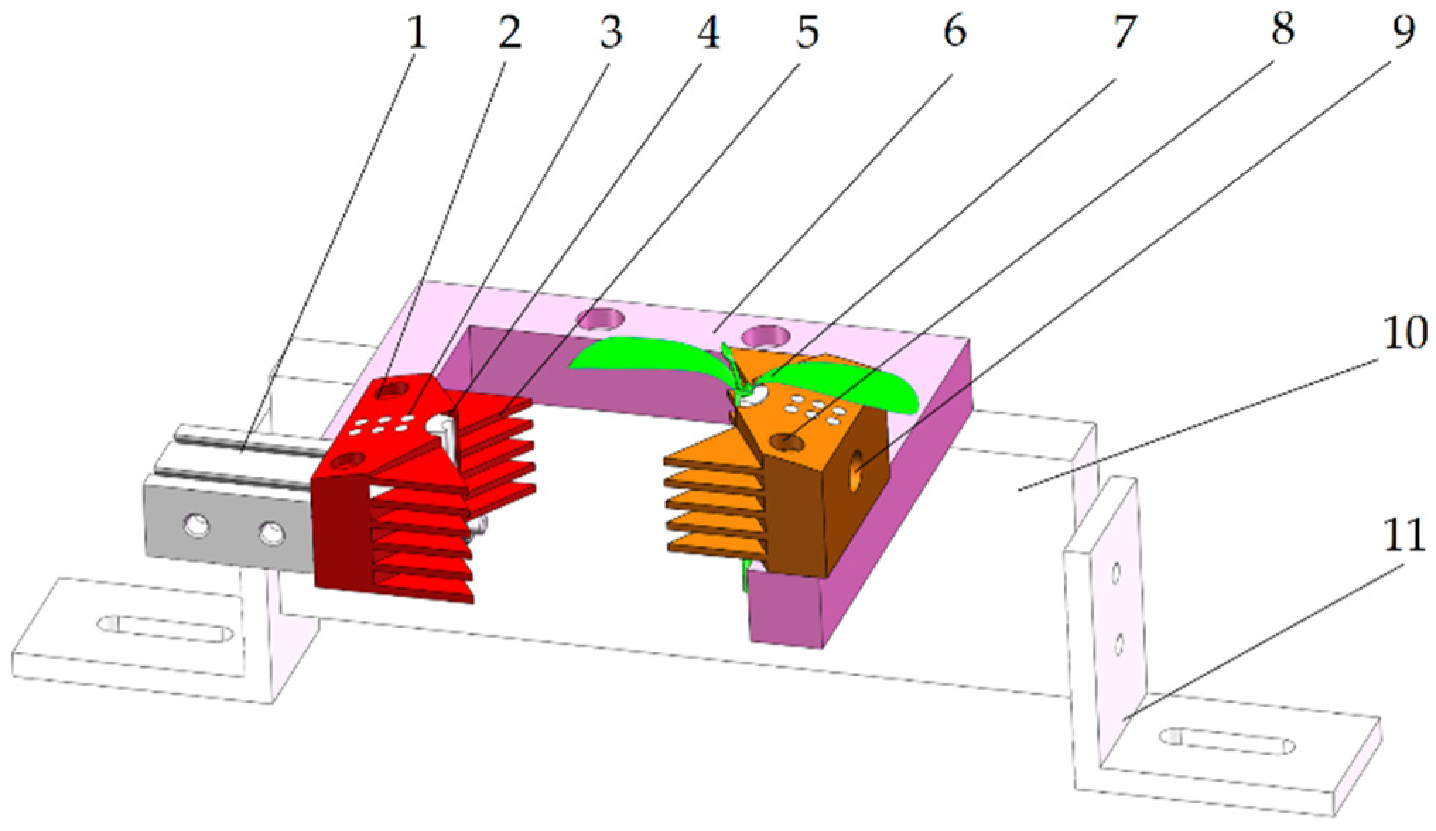
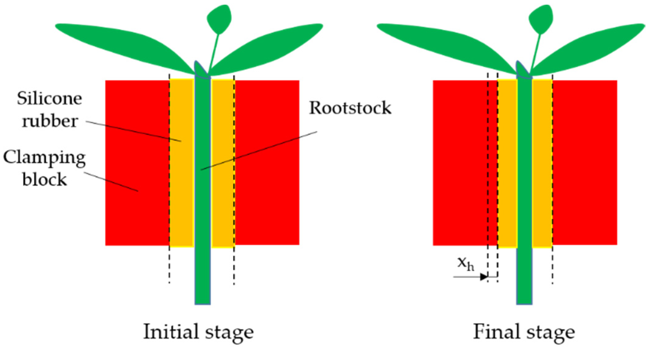
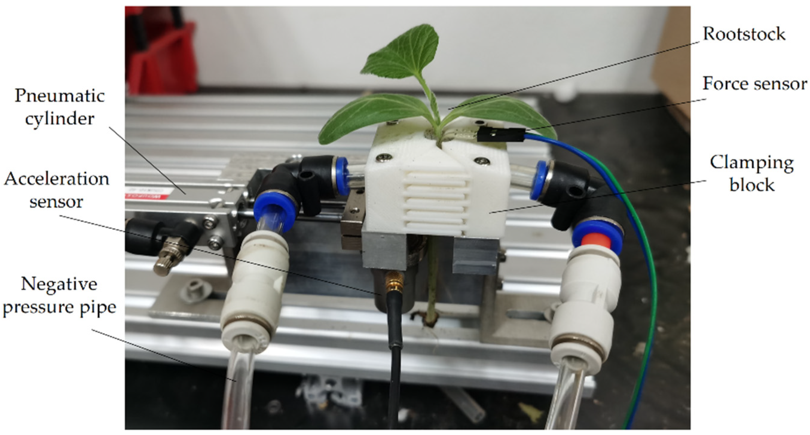
2.1. Rootstock Clamping Mechanism
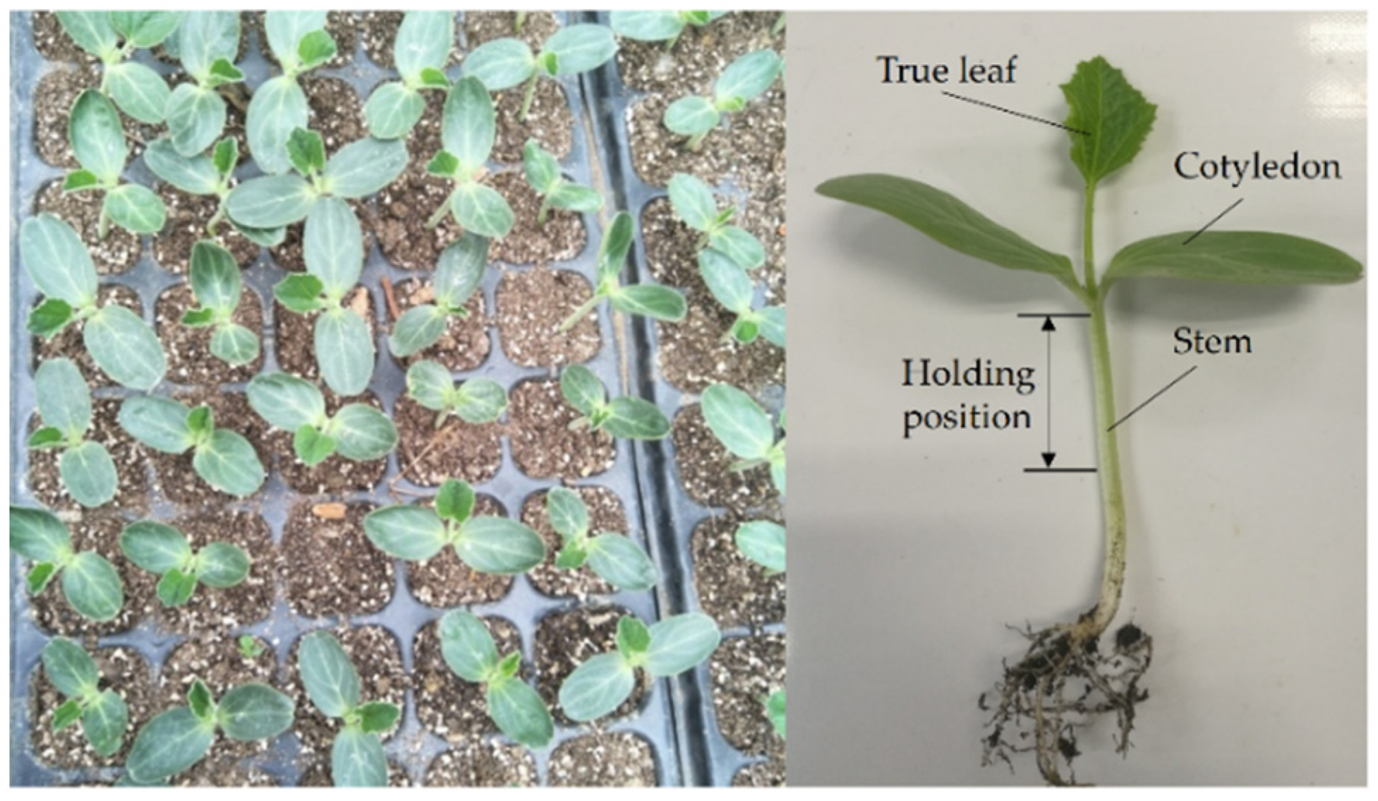
Currently, the clamping mechanism often uses a mechanical clamping method, which predisposes the rootstock to damage. To solve this problem, a flexible rootstock clamping device, based on the inclined inserted method, was designed in the previous study [20]. In the previous study, first, the structure of the clamping device was analyzed; then, the structural parameters and working parameters of the clamping device were optimized through experiments. This study will employ the clamping device to establish the deformation model and analyze the deformation law of the rootstock stem during holding. The clamping device mainly included a clamping mechanism, a seedling pressing mechanism and a pneumatic mechanism. The rootstock stem was held by the clamping mechanism, while the seedling pressing mechanism pressed the rootstock’s cotyledons onto the clamping blocks to fully expose the growth point and subsequently facilitate its removal. The pneumatic mechanism assisted in completing the entire holding process.
Mechanical damage often occurs when the rootstock is squeezed by the clamping mechanism during the holding process. Thus, the clamping mechanism represents the core component of the clamping device. A 3D diagram of the clamping mechanism is shown in Figure 1. During the holding process, the pneumatic cylinder drives the clamping block to hold the rootstock stem, while the positioning pieces on two clamping blocks can cross together to gather the stem in the middle and realize clamping positioning. To moderate the squeezing effect, the elastic silicone rubbers (food grade and 10° hardness) were positioned in the middle of the clamping blocks while the two rows of negative pressure air holes were arranged on the upper surface of clamping blocks to hold the rootstock’s cotyledons. The two clamping blocks were connected through the connecting frame using a connecting block, which was fixed onto the fixing frame.

2.2. Test Materials

We selected Yongzhen No. 5 cucurbit (Top-Yield Seed Technology Co., Ltd., Ningbo, China) as the experimental rootstock. Cucurbit seeds were first soaked in water for 12–16 h, then incubated under a constant temperature (28 °C) in a box to accelerate germination. Upon germination, the seeds were sown in plug trays and lined with a cultivation matrix (vermiculite:perlite:peat soil = 1:1:1). The experiment was conducted when cucurbit seedlings had one true unfolded leaf and the second true leaf exposed. Representative pictures of the rootstock seedlings are shown in Figure 2. The holding position was from the base of cotyledons to the stem, at 25–30 mm, according to the designed clamping mechanism, with subsequent tests performed on the holding position.

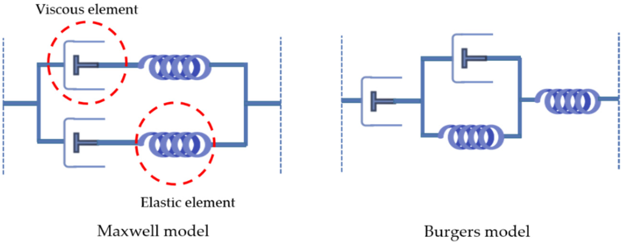
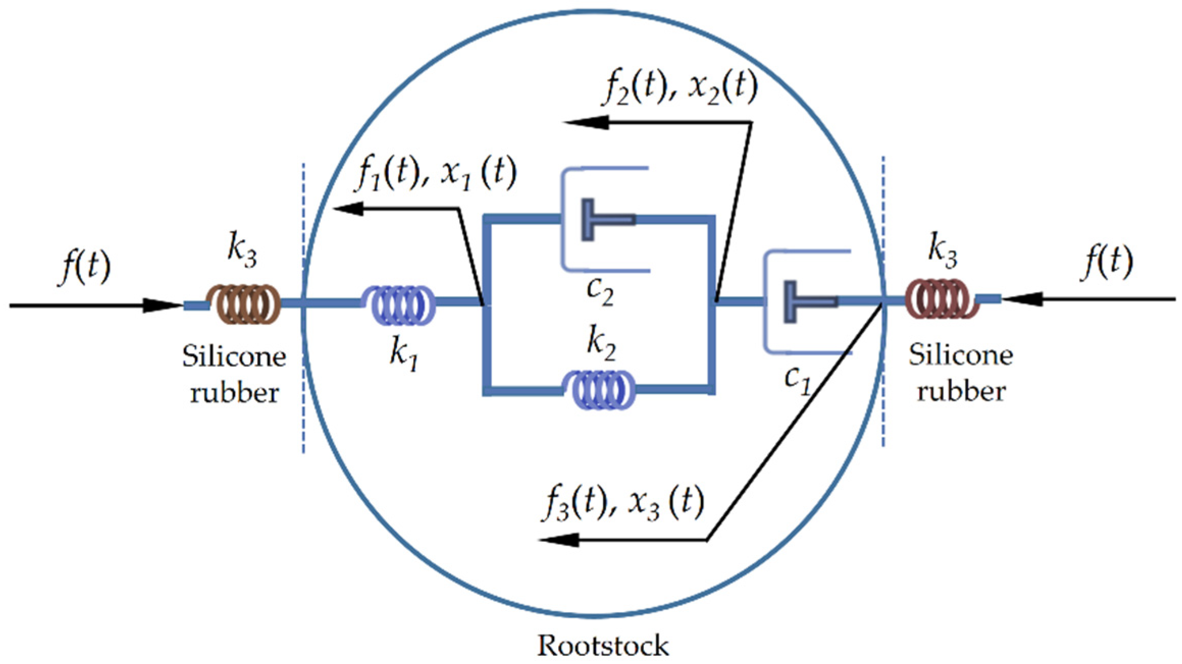
2.3. Establishment of a Creep Model
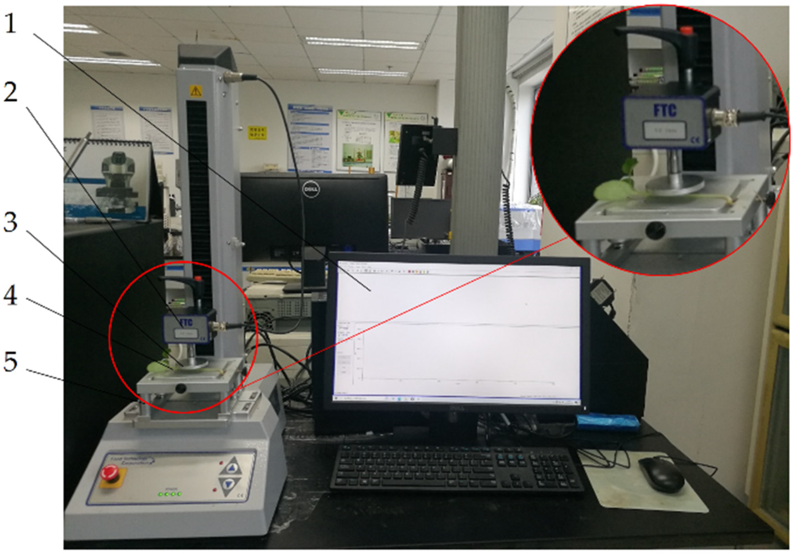
Vegetables and fruits belong to viscoelastic material and have rheological properties. Notably, the rootstock, being a plant, should also present the rheological properties under squeezing. Holding the rootstock generates contact force between the rootstock and the clamping mechanism, which inevitably causes deformations that can either be elastic or plastic. While elastic deformations are reversible, plastic ones can change the shape of the rootstock and influence both its internal and external qualities. Therefore, plastic deformations can cause mechanical damage to the rootstock during the holding operation [19].
Several rheological models, including the Maxwell, Kelvin and Burgers models, have been commonly applied [21]. Among them, a four-element Maxwell model—as shown in Figure 3, comprising two parallel units, each of which consist of elastic and viscous elements in series—has been effectively applied to approximate the relaxation curve [22]. The Kelvin model, which is a two-element model consisting of an elastic element and a viscous element in parallel, has been used to approximate creep behavior of rheological objects at constant stress. On the other hand, the Burgers model, as shown in Figure 3, is a more complex four-element model than the above models and consists of Maxwell and Kelvin elements in series [23]. Notably, the Burgers model enables detection of viscous and elastic deformations under the external forces and also mediates comprehensive identification of creep properties of viscoelastic materials [24].
In order to prevent the holding damage to the rootstock, silicone rubbers were arranged in the middle of the clamping blocks to make it flexible. The process of rootstock holding deformation is shown in Figure 4. Silicone rubber represented the elastic material; its mechanical properties under compression were obtained using a universal testing machine. To simplify the study process, we analyzed the rootstock and silicon rubber as a whole. In this study, we applied a four-element Burgers model to detect deformations in the rootstock. A summary of the relationship in the interaction model between the rootstock and the silicone rubber during the holding process is shown in Figure 5.
Under external force, the deformations can be divided into three layers, namely an elastic element (i = 1), a set of parallel viscoelastic unit (i = 2) and a viscous element (i = 3). Based on the relationship between the contact force f(t) and the deformation response x(t) of the rootstock in each layer, the following equations are obtained [14,25]:
f ( t ) = f 1 ( t ) = f 2 ( t ) = f 3 ( t )
x ( t ) = i = 1 3 x i ( t )
f 1 ( t ) = k 1 x 1 ( t )
f 2 ( t ) = k 2 x 2 ( t ) + c 2 x ˙ 2 ( t )
f 3 ( t ) = c 1 x ˙ 3 ( t )
During the holding process, the rootstock deformation x(t) and clamping force f(t) satisfy the following equation.
x ( t ) = x h ( t ) 2 f ( t ) k 3
where xh(t) denotes total deformation, including deformation of the rootstock and that of the silicone rubber.
The rheological constitutive equation for rootstocks can be obtained from Equations (1)–(6).
b 2 x ¨ h ( t ) + b 1 x ˙ h ( t ) = a 2 f ¨ ( t ) + a 1 f ˙ ( t ) + f ( t )
where
b 2 = c 1 c 2 k 2
b 1 = c 1
a 2 = c 1 c 2 ( 2 k 1 + k 3 ) k 1 k 2 k 3
a 1 = 2 k 1 k 2 c 1 + k 3 ( k 2 c 1 + k 1 c 2 + k 1 c 1 ) k 1 k 2 k 3
The constitutive equation coefficients a1, a2, b1 and b2 can all be obtained from creep model parameters k1, k2, c1 and c2, while the creep model parameters can be determined in creep tests by using the following equation [14,18].
x ( t ) = f 0 k 1 + f 0 c 1 t + f 0 k 2 ( 1 e k 2 c 2 t )
x(t)—The deformation, mm;
t—The loading time, s;
f0—The loading force, N;
k1—The instantaneous elasticity coefficient, N·mm−1;
c1—The series viscous coefficient, N·s·mm−1;
c2—The parallel viscous coefficient, N·s·mm−1;
k2—The retarded elasticity coefficient, N·mm−1.

2.4. Test Methods

Rootstocks were measured using a vernier caliper (Minnet Industrial Co., Ltd., Shanghai, China), prior to creep tests. The average sizes of the rootstocks we selected were long axe 3.40 ± 0.35 mm, short axe 2.61 ± 0.24 mm, cotyledon width 20.12 ± 1.66 mm and single cotyledon length 31.87 ± 3.14 mm. Creep tests were conducted using the TMS—PRO texture analyzer (Food Technology Corporation, Sterling, VA, USA), shown in Figure 6. In summary, the rootstock was first placed horizontally on a stage then the probe moved rapidly along it at a pre-test velocity. Upon reaching an initial contact force, the probe continued to move at the test velocity, then stopped and maintained at the state according to the loading time after reaching the loading force determined by the pre-test. Finally, the loading force was unloaded, the probe returned to the set height at the post-test velocity and the single test was completed. The operating parameters of TMS-PRO texture analyzer are listed in Table 1.

2.5. Test Design and Data Analysis

In this test, we selected test velocity and loading force as test factors for investigating the effect of rheological parameters on the rootstock deformation. Particularly, test velocity was set at 10, 60, 120, 180 and 240 mm/min [26,27], whereas the loading force ranged from 1 to 5 N in increments of 1 N. A total of nine groups for single factor experiments were carried out (30 rootstock seedlings in each group). In addition, the damage rate of the stem was calculated for each group in this study and the damage rate is the ratio of the number of damaged stems to the total number of stems.
All data were preliminarily processed using Microsoft Excel 2013 (Microsoft Corp., Redmond, WA, USA), then fitted using custom-written functions in Origin 8.5 (OriginLab, Northampton, MA, USA) software to obtain the viscoelastic parameters of the creep model. The analysis of variance (ANOVA) was conducted to evaluate the significance, at p < 0.05, using SPSS software version 19.0 (IBM, Armonk, NY, USA). The software MATLAB R2019a (Mathworks, Natick, MA, USA) was used to solve the equations.

3. Results and Discussion

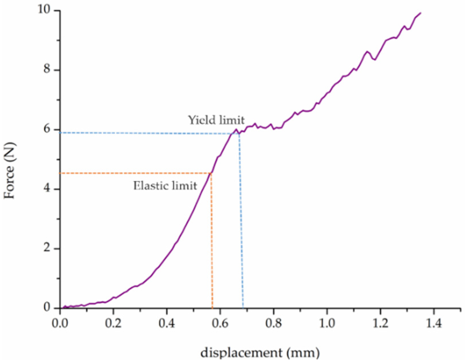
3.1. Compression Test
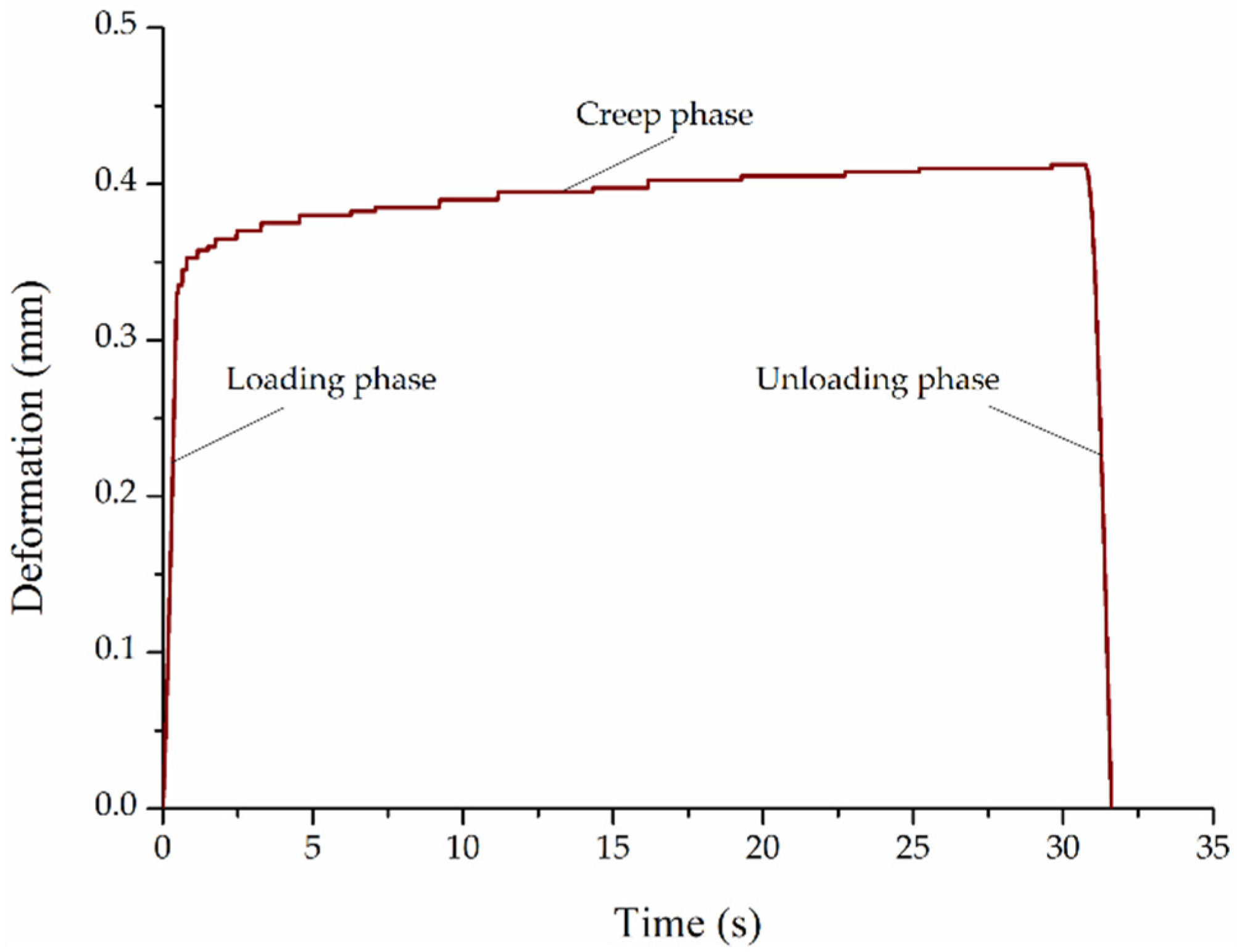
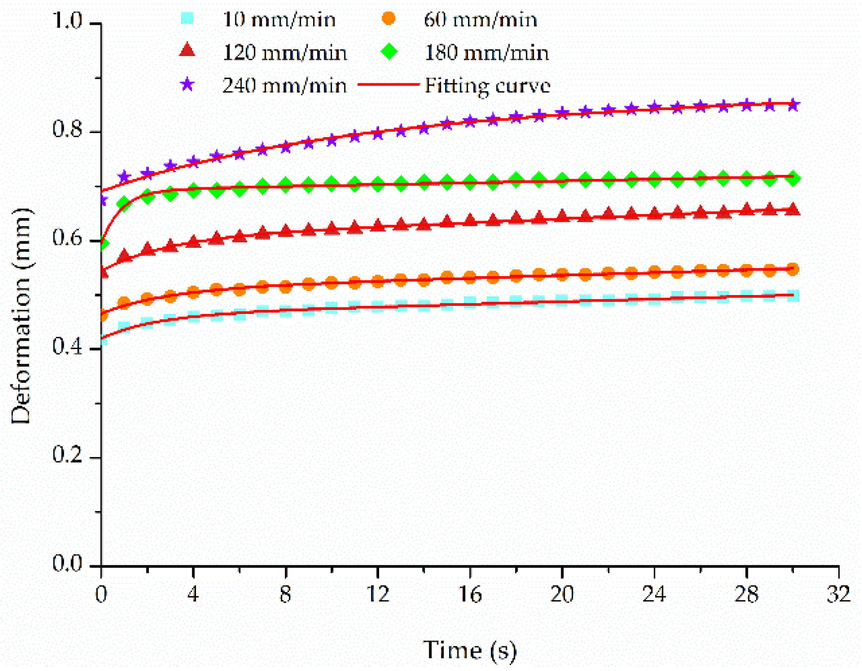
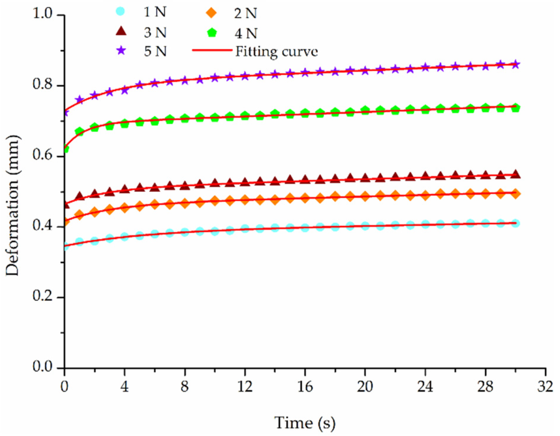
It is necessary to carry out compression tests on the rootstock stem prior to subjecting it to creep tests, as this helps in determining the stem’s limit force. Probes with a cylindrical shape (15 mm diameter and 3 mm thickness) were used in the test. From the compression test results, shown in Figure 7, an elastic limit appeared during compression. Particularly, a rootstock’s stem pressure less than the elastic limit implied that the rootstock was in the safe clamping range; otherwise, it would cause damage to the rootstock. Therefore, the elastic limit was used as the basis for investigating whether the rootstock was safe. Results of the compression test revealed an average elastic limit value of 4.45 N.

3.2. Creep Test

The deformation–time curve of the creep test is shown in Figure 8. During the test, the rootstock was quickly loaded to a constant load (loading phase), while the probe was maintained at a constant load for 30 s (creep phase). The results indicated that the deformation gradually increased with the increase in time, although the increase progressively decreased. Meanwhile, we noted an obvious occurrence in creep deformation, which later reversed upon unloading. To obtain the rootstock’s viscoelastic parameters during the holding process, this study only analyzed the creep deformation process (creep phase).

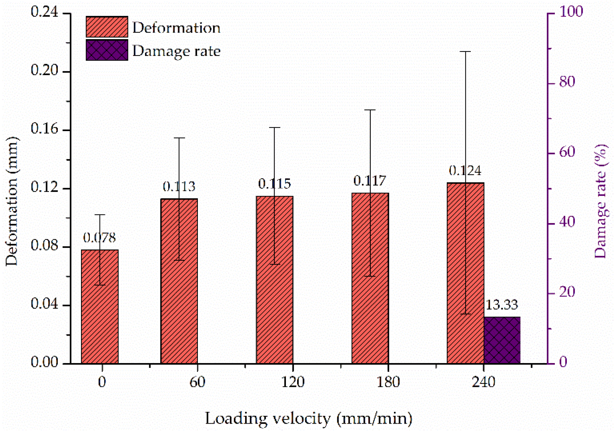
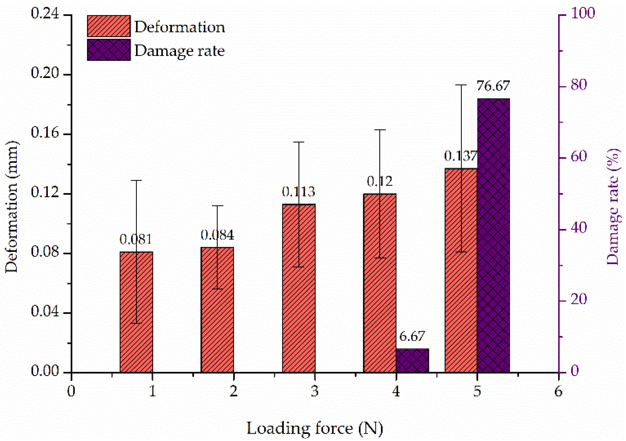
3.3. Single-Factor Experiment Analysis and Discussion

The results from the single factor experiments targeting test velocity are shown in Figure 9. Notably, a slower test velocity resulted in less creep deformation (Figure 9). This was attributed to the fact that a slower test velocity caused more adequate deformation of the rootstock in the loading phase, which in turn weakened the ability of continued deformation during the creep phase [27]. Figure 10 shows the deformation and damage rate during creep under various test velocities. The deformation gradually increased with an increasing test velocity. The trend from 60 mm/min to 180 mm/min, however, was not apparent. When the test velocity reached 240 mm/min, the appearance of the plastic deformation led to the damage of some rootstock stems. Meanwhile, the deformation showed significant increase. This may be because a larger loading velocity produced a greater instantaneous impact load when first touching the stem [26].
The fitting viscoelastic parameters of the creep model under various test velocities are shown in Table 2. Theoretically, the instantaneous elasticity coefficient k1 tend to be a certain value in the constant loading force condition. However, from Table 2, the instantaneous elasticity coefficient k1 showed a slow change. The reason was that the rootstock was not a rigid material and the force transmission inside the rootstock was nonlinear, resulting in a different force on each section [28]. Moreover, no obvious rule for the retarded elasticity coefficient k2, series viscous coefficient c1 and parallel viscous coefficient c2 was observed as the test velocity increased. Consequently, the loading velocity less than 240 mm/min should be selected in follow-up studies to reduce the test error. In addition, Figure 9 and Table 2 show that the Burgers model offered a good fitting (R2 > 0.98) for the creep curves of rootstock.
From the creep test under various test velocities, a larger loading velocity may cause damage to the stem, which in turn increased the test error. A smaller velocity increased the test time to observe the stem deformation and it would affect the test results. Due to good fitting at 60 mm/min, a loading velocity of 60 mm/min was used for subsequent testing. The results from the single factor experiment targeting the loading force are shown in Figure 11. In the creep test, the deformation produced by instantaneous elasticity coefficient k1, retarded elasticity coefficient k2, series viscous coefficient c1 and parallel viscous coefficient c2 increased with the increasing time and force. However, because the growth of deformation produced by c1 was slower than k1, the creep curve showed a slowly rising process. As shown in Figure 11, the creep deformation increased gradually with an increase in loading force. The increase first exhibited a relatively wide variation before leveling off. When the loading force was smaller, the deformation would not increase with the increase in loading time due to the strain saturation phenomena [29]. Figure 12 shows the deformation and damage rate during the creep under various loading forces. As the loading force increased, the creep deformation gradually increased. When the loading force approached the elastic limit, some rootstock stems underwent plastic deformation, which in turn caused damage to the stems. The damage increased with a further increase in loading force, thus resulting in the increase in creep deformation. The same conclusion was obtained by Wang [30] and Wu [31]. Therefore, the holding force should be controlled below 4 N to reduce the creep deformation and prevent holding damage during rootstock holding.
The results of the fitting viscoelastic parameters for the creep model under various loading forces are shown in Table 3. As seen in Table 3, a stronger loading force generated a larger instantaneous elasticity coefficient k1 which was accompanied by a larger retarded elasticity coefficient k2. These results were consistent with findings from related studies [32,33]. Additionally, the series viscous coefficient c1 and parallel viscous coefficient c2 were also greater. From Figure 11 and Table 3, it can be seen that the fitting viscoelastic parameters from the creep model were all greater than 0.98, which indicated that the Burgers model can appropriately express the rootstock’s creep characteristics.
The analysis of variance (one-way ANOVA) results, indicating the effect of test factors (loading force and test velocity) on creep deformation, are shown in Table 4. It can be seen from Table 4 that the p-value for loading force and test velocity were both less than 0.05, indicating that the loading force and test velocity significantly affected creep deformation (p < 0.05). Moreover, the F-value indicated that the influence of loading force on the creep deformation was greater than test velocity. Therefore, more attention should be directed to adjusting the loading force than test velocity to prevent holding damage under conditions of effective holding during the holding process.

3.4. Holding Test for Rootstock

To investigate the damage to rootstocks in holding, a clamping mechanism was used to perform the holding test. The physical drawing of the clamping mechanism is shown in Figure 13. The contact force was measured by a force sensor (2 kg, Chengke Electronic Technology Co., Ltd., Shanghai, China). Unlike the texture analyzer, the force during holding can be only adjusted by changing the velocity of the pneumatic cylinder. The acceleration sensor (50 g, Chengke Electronic Technology Co., Ltd., Shanghai, China) measured acceleration, which was then integrated to obtain the velocity.
The representative force–time curve with and without silicone rubber is shown in Figure 14. From Figure 14, the force without silicone rubber was greater than that with silicone rubber under the same velocity condition. Moreover, the clamping block produced a large instantaneous impact load without silicone rubber when in contact with just the stem. This was consistent with the results obtained by the creep test. However, the force–time curve was relatively stable with silicone rubber. This is because the deformation occurred while force acting on the silicone rubber and a part of energy was converted to deformation energy of silicone rubber, thus the force acting on the stem decreased. The results indicated that the damage rate exceeded 90% without silicone rubber, while there was no damage with silicone rubber.

4. Conclusions

In this study, the four-element Burgers model was utilized to present the viscoelastic behavior and the deformation characteristics of the rootstock. Creep tests were conducted on the rootstocks to obtain the viscoelastic parameters of the Burgers model, using cucurbit (commonly used in watermelon grafting) as an example. The obtained results indicated that this model fitted well and could describe the creep characteristics of the rootstock. Additionally, we analyzed the effect of viscoelastic parameters on rootstock deformation under various test conditions and found that creep deformation gradually increased with the increase in loading force and test velocity. Notably, the rootstock stems showed some damage due to the occurrence of plastic deformation when the loading force was 4 N, which significantly affected the holding effect. One-way ANOVA results showed that the influence of the loading force on the creep deformation was greater than the test velocity. The holding test results without silicone rubber was in accordance with the creep test. Additionally, the clamping mechanism with silicone rubber can effectively prevent the damage to the stem, compared to without silicone rubber. Taken together, these results affirm the need to control the holding force below 4 N to reduce creep deformation and prevent holding damage during the watermelon grafting. These findings are expected to guide future explorations into the damage mechanism during rootstock holding.

Author Contributions

Methodology, K.W. and J.L. (Jianping Li); software, K.W., W.L., C.L. (Congcong Li) and C.L. (Chen Li); validation, K.W.; formal analysis, K.W. and C.L. (Chen Li); investigation, K.W.; data curation, K.W.; writing—original draft preparation, K.W.; writing—review and editing, J.L. (Jianzhong Lou) and J.L. (Jianping Li); visualization, K.W. and C.L. (Chen Li); supervision, J.L. (Jianping Li); project administration, J.L. (Jianping Li); funding acquisition, J.L. (Jianping Li). All authors have read and agreed to the published version of the manuscript.

Funding

This research was funded by National Natural Science Foundation of China (Grant No. 51775490).

Data Availability Statement

The data presented in this study are available on demand from the first author at (kang_wu@zju.edu.cn).

Acknowledgments

The authors gratefully acknowledge the financial support provided by the National Natural Science Foundation of China (Grant No. 51775490). We also appreciate the work of the editors and the reviewers of the paper.

Conflicts of Interest

The authors declare no conflict of interest.

References

  1. Food and Agriculture Organization (FAO). STAT 2019. Available online: http://www.fao.org/faostat/zh/#data/QC (accessed on 9 August 2021).
  2. Sun, Y.; Wang, Y.; Han, L.R.; Zhang, X.; Feng, J.T. Antifungal activity and action mode of cuminic acid from the seeds of Cuminum cyminum L. against Fusarium oxysporum f. sp. Niveum (FON) causing Fusarium wilt on watermelon. Molecules 2017, 22, 2053. [Google Scholar] [CrossRef] [Green Version]
  3. Ling, N.; Zhang, W.; Wang, D.; Mao, J.; Huang, Q.; Guo, S.; Shen, Q. Root exudates from grafted-root watermelon showed a certain contribution in inhibiting Fusarium oxysporum f. sp. Niveum. PLoS ONE 2013, 8, e63383. [Google Scholar] [CrossRef]
  4. Bie, Z.; Nawaz, M.A.; Huang, Y.; Lee, J.M.; Colla, G. Introduction of vegetable grafting. In Proceedings of the Vegetable Grafting: Principles and Practices, CAB International, Wallingford, UK, 5 June 2017; pp. 1–21. [Google Scholar] [CrossRef]
  5. Lv, H.; Cao, H.; Nawaz, M.A.; Hamza, S.; Huang, Y.; Cheng, F.; Kong, Q.; Bie, Z. Wheat intercropping enhances the resistance of watermelon to fusarium wilt. Front. Plant Sci. 2018, 9, 696. [Google Scholar] [CrossRef] [PubMed] [Green Version]
  6. Rouphael, Y.; Venema, J.; Edelstein, M.; Savvas, D.; Colla, G.; Ntatsi, G.; Ben-Hur, M.; Kumar, P.; Schwarz, D. Grafting as a tool for tolerance of abiotic stress. In Proceedings of the Vegetable Grafting: Principles and Practices, CAB International, Wallingford, UK, 5 June 2017; pp. 171–215. [Google Scholar] [CrossRef]
  7. Lee, J.M.; Kubota, C.; Tsao, S.J.; Bie, Z.; Echevarria, P.H.; Morra, L.; Oda, M. Current status of vegetable grafting: Diffusion, grafting techniques, automation. Sci. Hortic. 2010, 127, 93–105. [Google Scholar] [CrossRef]
  8. Zhang, K.L.; Chu, J.; Zhang, T.Z.; Yin, Q.; Kong, Y.S.; Liu, Z. Development status and analysis of automatic grafting technology for vegetables. Trans. CSAM 2017, 48, 1–13. [Google Scholar] [CrossRef]
  9. Mohamed, F.; El-Hamed, K.; Elwan, M.; Hussien, M.A. Impact of grafting on watermelon growth, fruit yield and quality. Veg. Crop. Res. Bull. 2012, 76, 99–118. [Google Scholar] [CrossRef]
  10. Devi, P.; Lukas, S.; Miles, C. Advances in watermelon grafting to increase efficiency and automation. Horticulturae 2020, 6, 88. [Google Scholar] [CrossRef]
  11. Lou, J.Z. Mechanism Study and Optimization Design of Inclined-Insert Grafting Device of Cucurbita Vegetable. Ph.D. Thesis, Zhejiang University, Hangzhou, China, 2014. [Google Scholar]
  12. Jiang, K. Study on Mechanism and Experimental Device of Splice Mechanical Grafting of cucurbit. Ph.D. Thesis, Northeast Agricultural University, Harbin, China, 2019. [Google Scholar]
  13. Lou, J.Z.; Wu, K.; Chen, J.Y.; Ma, G.Y.; Li, J.P. Design and test of self-adaptive stock cotyledons pressing and clamping mechanism for oblique inserted grafting of Cucurbitaceous vegetables. Trans. CSAE 2018, 34, 76–82. [Google Scholar] [CrossRef]
  14. Zou, L.; Yuan, J.; Liu, X.; Li, J.; Niu, Z. Burgers viscoelastic model-based variable stiffness design of compliant clamping mechanism for leafy greens harvesting. Biosyst. Eng. 2021, 208, 1–15. [Google Scholar] [CrossRef]
  15. Higashimori, M.; Yoshimoto, K.; Kaneko, M. Active shaping of an unknown rheological object based on deformation decomposition into elasticity and plasticity. In Proceedings of the IEEE International Conference on Robotics and Automation, Anchorage, AK, USA, 3–7 May 2010. [Google Scholar] [CrossRef]
  16. Sakamoto, N.; Higashimori, M.; Tsuji, T.; Kaneko, M. An optimum design of robotic hand for handling a viscoelastic object based on maxwell model. In Proceedings of the IEEE International Conference on Robotics and Automation, Roma, Italy, 10–14 April 2007. [Google Scholar] [CrossRef]
  17. Taylor, L.S.; Lerner, A.L.; Rubens, D.J.; Parker, K.J. A kelvin-voight fractional derivative model for viscoelastic characterization of liver tissue. In Proceedings of the ASME International Mechanical Engineering Congress & Exposition, New Orleans, LA, USA, 17–22 November 2002. [Google Scholar] [CrossRef] [Green Version]
  18. Sakamoto, N.; Higashimori, M.; Tsuji, T.; Kaneko, M. An optimum design of robotic food handling by using Burger model. Intell. Serv. Robot. 2009, 2, 53–60. [Google Scholar] [CrossRef]
  19. Zhang, B.; Zhou, J.; Meng, Y.; Zhang, N.; Gu, B.; Yan, Z.; Idris, S. Comparative study of mechanical damage caused by a two-finger tomato gripper with different robotic grasping patterns for harvesting robots. Biosyst. Eng. 2018, 171, 245–257. [Google Scholar] [CrossRef]
  20. Wu, K.; Lou, J.Z.; Li, C.; Li, J.P. Experimental evaluation of rootstock clamping device for inclined inserted grafting of melons. Agriculture 2021, 11, 736. [Google Scholar] [CrossRef]
  21. Nehdi, M.; Rahman, M.A. Estimating rheological properties of cement pastes using various rheological models for different test geometry, gap and surface friction. Cem. Concr. Res. 2004, 34, 1993–2007. [Google Scholar] [CrossRef]
  22. Senoo, T.; Koike, M.; Murakami, K.; Ishikawa, M. Impedance control design based on plastic deformation for a robotic arm. IEEE Robot. Autom. Lett. 2016, 2, 209–216. [Google Scholar] [CrossRef]
  23. Zhang, N. Research Oil Online Estimation of Tomato Viscoelastic Parameters. Master’s Thesis, Nanjing Agricultural University, Nanjing, China, 2017. [Google Scholar]
  24. Sun, X.; Koksel, F.; Nickerson, M.T.; Scanlon, M.G. Modeling the viscoelastic behavior of wheat flour dough prepared from a wide range of formulations. Food Hydrocolloid 2019, 98, 105129. [Google Scholar] [CrossRef]
  25. Zhou, J.; Meng, Y.; Zhang, N.; Yan, Z. Impact of robot grasping control modes on mechanical damage of tomato. Trans. CSAM 2017, 48, 21–27. [Google Scholar] [CrossRef]
  26. Sun, G.H. Studies on Rheological Properties of Characteristic Nectarine. Master’s Thesis, Jiangsu University, Zhenjiang, China, 2005. [Google Scholar]
  27. Guo, W.B.; Wang, Z.P.; Hu, F.; Hou, Z.B.; De, X.H. Study on creep properties of potato pulp. Feed Res. 2021, 11, 115–118. [Google Scholar] [CrossRef]
  28. Li, W. Study on Creep Properties of Maize Straw Rubbed during Open Compression. Master’s Thesis, Inner Mongolia Agriculture University, Hohhot, China, 2011. [Google Scholar]
  29. Li, X.Y.; Wang, W.; Sun, L.; Feng, G.H. A study on rheological characteristics of apple I. testing creep properties. J. Northwest A F Univ. 1991, 19, 70–74. [Google Scholar]
  30. Wang, W.; Cheng, Y.; Tan, G.; Tao, J. Analysis of aggregate morphological characteristics for viscoelastic properties of asphalt mixes using simplex lattice design. Materials 2018, 11, 1908. [Google Scholar] [CrossRef] [Green Version]
  31. Wu, F.; Chen, J.; Zou, Q. A nonlinear creep damage model for salt rock. Int. J. Damage Mech. 2018, 28, 1–14. [Google Scholar] [CrossRef]
  32. Gao, J.J.; Guo, W.B.; Yu, Z.H. Study on the compressibility of potato residue. Food Mach. 2018, 34, 50–53. [Google Scholar] [CrossRef]
  33. Lu, L.; Cao, J.; Li, G. Giant reversible elongation upon cooling and contraction upon heating for a crosslinked cis poly (1,4-butadiene) system at temperatures below zero Celsius. Sci. Rep. 2018, 8, 14233. [Google Scholar] [CrossRef]
Figure 1. A 3D diagram of the clamping mechanism [20]. 1. Pneumatic cylinder. 2. Clamping block. 3. Negative pressure air hole. 4. Silicone rubber. 5. Positioning piece. 6. Connecting frame. 7. Rootstock seedling. 8. Connecting hole. 9. Negative pressure inlet. 10. Connecting block. 11. Fixing frame.
Agriculture 11 01266 g001
Figure 2. Rootstock seedlings.
Agriculture 11 01266 g002
Figure 3. Two viscoelastic models.
Agriculture 11 01266 g003
Figure 4. The deformation process of rootstock holding.
Agriculture 11 01266 g004
Figure 5. Model of the interaction relationship between the rootstock and the silicone rubber.
Agriculture 11 01266 g005
Figure 6. TMS-PRO texture analyzer. 1. Software. 2. Force sensor. 3. Probe. 4. Rootstock. 5. Stage.
Agriculture 11 01266 g006
Figure 7. Representative force–displacement curve of the compression test for rootstock.
Agriculture 11 01266 g007
Figure 8. Representative deformation–time curve of creep test for rootstock.
Agriculture 11 01266 g008
Figure 9. The representative deformation with respect to time under various test velocities. Note: the loading force was 3 N.
Agriculture 11 01266 g009
Figure 10. The deformation and damage rate during creep under various test velocities. Note: the loading force was 3 N.
Agriculture 11 01266 g010
Figure 11. The representative deformation with respect to time under various loading forces. Note: the test velocity was 60 mm/min.
Agriculture 11 01266 g011
Figure 12. The deformation and damage rate during creep under various loading forces. Note: the test velocity was 60 mm/min.
Agriculture 11 01266 g012
Figure 13. Physical drawing of the clamping mechanism.
Agriculture 11 01266 g013
Figure 14. The representative force–time curve with and without silicone rubber.
Agriculture 11 01266 g014
Table 1. Operating parameters of the texture analyzer.
ParameterValue
Force sensor100 N
The diameter of probe50 mm
The set height of probe10 mm
Pre-test velocity30 mm/min
Test velocity10–240 mm/min
Post-test velocity30 mm/min
Initial contact force0.1 N
Loading force1–5 N
Sampling frequency1000 points/s
Loading Time30 s
Table 2. The fitting viscoelastic parameters of the creep model under various test velocities.
Test Velocity/
(mm/min)
k1/N·mm−1k2/N·mm−1c1/N·s·mm−1c2/N·s·mm−1R2
106.2374.483031.19313.930.992
605.3352.252486.59159.500.991
1206.8653.982755.67154.580.990
1805.2879.032882.64225.190.982
2405.6665.282823.59254.570.989
Table 3. The fitting viscoelastic parameters of creep model under various loading forces.
Loading Force/
N
k1/N·mm−1k2/N·mm−1c1/N·s·mm−1c2/N·s·mm−1R2
13.4028.581081.8769.740.985
24.2143.583220.18130.120.987
35.3352.252486.59159.500.991
46.5973.502643.97152.660.991
56.9171.403140.74151.670.991
Table 4. ANOVA results for creep deformation.
SourceSum of SquaresdfMean SquareF-Valuep-ValueSignificant
Loading force0.06940.0176.181<0.0001Yes
Test velocity0.03940.013.5150.008Yes
Error0.724261
Total3.950270
Publisher’s Note: MDPI stays neutral with regard to jurisdictional claims in published maps and institutional affiliations.

