Article

Cracking Behavior of RC Beams Strengthened with Different Amounts and Layouts of CFRP

by
Muhammad Umair Saleem
1,*,
Hisham Jahangir Qureshi
1,
Muhammad Nasir Amin
1,
Kaffayatullah Khan
1 and
Hassan Khurshid
2
1
Department of Civil and Environmental Engineering, College of Engineering, King Faisal University, 31982 Hofuf, Alahsa, Saudi Arabia
2
Department of Mechanical Engineering, College of Engineering, King Faisal University, 31982 Hofuf, Alahsa, Saudi Arabia
*
Author to whom correspondence should be addressed.
Appl. Sci. 2019, 9(5), 1017; https://doi.org/10.3390/app9051017
Submission received: 4 February 2019 / Revised: 7 March 2019 / Accepted: 7 March 2019 / Published: 12 March 2019
(This article belongs to the Special Issue Fatigue and Fracture of Non-metallic Materials and Structures)

Abstract

:

Featured Application

This study provides the valuable data to assess the failure mechanism of CFRP strengthened reinforced concrete beams and structural systems.

Abstract

The bending and shear behavior of RC beams strengthened with Carbon Fiber-Reinforced Polymers (CFRP) is the primary objective of this paper, which is focused on the failure mechanisms and on the moment-curvature response prior-to, and post, strengthening with different amounts and layouts of the CFRP reinforcement. Seven reinforced concrete beams were tested in 4-point bending, one without any CFRP reinforcement (control beam, Specimen C1), four with the same amount of CFRP in flexure but with different layouts of the reinforcement for shear (Specimens B1–B4), and two with extra reinforcement in bending, with and without reinforcement in shear (Specimens B6 and B5, respectively). During each test, the load and the mid-span deflection were monitored, as well as the crack pattern. The experimental results indicate that: (a) increasing the CFRP reinforcement above certain levels does not necessarily increase the bearing capacity; (b) the structural performance can be optimized through an appropriate combination of CFRP flexural and shear reinforcement; and (c) bond properties at the concrete–CFRP interface play a vital role, as the failure is very often triggered by the debonding of the CFRP strips. The experimental values were also verified analytically and a close agreement between the analytical and experimental values was achieved.

1. Introduction

The Kingdom of Saudi Arabia, as well as rest of the world, contains a wide range of reinforced concrete infrastructure which ranges from small residential houses to multi-story buildings, towers, and pre-stressed concrete bridges. The majority of the infrastructure in Saudi Arabia was designed and constructed on old design codes, standards, and specifications, and as a result of that, it is currently experiencing weathering because of harsh climate, saltwater, acid attack, extreme temperature changes, and due to the inferior quality of building material. There is a necessity to strengthen old existing infrastructure in Saudi Arabia, which lacks in strength and stiffness. There are many different ways to strengthen reinforced concrete structures, and one of the most common methods is the application of CFRP (Carbon Fiber Reinforced Polymer) to the reinforced concrete member.
CFRP has been widely used for the purpose of strengthening reinforced concrete, masonry, and steel infrastructure. Over the past few decades, many researchers have proved the suitability of CFRP material for structures composed of different materials, stiffness, and ductility [1,2,3,4,5,6]. By adopting the correct retrofitting technique, CFRP can significantly increase the shear and flexure strength of concrete structures as compared to the normal concrete structure. CFRP gains its strength via epoxy, which is the glue that makes a bond of CFRP with the concrete surface. Flexure, shear, and compression cracks can be prevented in reinforced concrete beams with the help of CFRP application. The benefit of using CFRP retrofitting comes from its low density and its resistance to higher tensile forces, fatigue, and corrosion.
However, the debonding failure mechanism, structural ductility, and long-term durability are the main problems, which CFRP is facing due to poor bonding and reduced vapor pressure [7,8,9]. Fracture of CFRP concrete beams is mainly attributed due to debonding of CFRP from the concrete surface. Hence, flexural strength, failure behavior, and structural ductility are the most important parameters that are always under consideration in structural design, especially when the structure is located in the higher earthquake zone region. CFRP is a material which is brittle in nature and fails suddenly, and has a linear elastic behavior up until failure, i.e., the tensile failure strain of FRP ranges from 2% to 4% [6]. Once the failure strain is reached, CFRP shows no signs of warning, breaks suddenly, and results in the loss of its strength. This behavior of low ductility in reinforced concrete structures retrofitted with CFRP is not desirable, as it does not provide any kind of early warning before failure, thus resulting in the sudden collapse of the structure.

2. Literature Review

CFRP has been widely used in the past for repair and rehabilitation of civil infrastructure that was showing signs of deterioration and distress due to aging. If applied properly, CFRP can increase the service life of the structure. CFRP is a brittle material and usually fails (i.e., debonding or horizontal crack propagation) at a lower load level, hence the ultimate capacity of the reinforced concrete structural member is very hard to achieve [10]. In the past, many researchers conducted experiments on reinforced concrete beams retrofitted in flexure by CFRP and resulting failure patterns were observed.
Arduini and Nanni [11] conducted a parametric analysis to investigate the effects of CFRP reinforcement on serviceability, strength, and failure mechanisms of repaired RC beams. They presented the results of their analysis in terms of repaired/un-repaired strength and deflection ratios. They observed that a brittle failure mechanism can develop at loads much lower than expected when considering only flexural performance of the FRP Strengthened beams. Their research work also concluded that the application of CFRP reinforcement can considerably result in an increase in load-bearing capacity and can also limit deflection at the service level. Smith and Teng [12] conducted a comprehensive review of existing plate debonding strength models that were presented by many researchers in past. Each model was summarized and classified into one of the three categories based on the considered approach. Teng et al. [13] conducted extensive research that has been carried out in recent years on the use of fiber-reinforced polymer (FRP) composites for the purpose of strengthening of reinforced concrete (RC) structures. Their paper provides a concise review of existing research on the behavior and strength of FRP-strengthened RC structures, with a strong focus on those studies that contribute directly to the development of strength models. Topics that were covered in their research work includes flexural and shear strengthening of beams, flexural strengthening of slabs, and strengthening of columns subjected to both static and seismic loads. For each of the topics covered, the methods of strengthening were first explained, followed by a description of the common failure modes. Kotynia [14] conducted tests on reinforced concrete (RC) beams that were strengthened externally with CFRP strips in flexure only. The flexural behavior of the beams, as well as their failure modes, were discussed in detail. Teng and Chen [15] provided a summary of debonding failure modes of reinforced concrete beams that were strengthened externally with FRP reinforcement. Their paper addressed the following three issues: (a) classification of debonding failure modes; (b) mechanisms and processes of debonding failures; (c) and theoretical models for debonding failures.
Kang et al. [10] conducted a detailed review of previous research programs that were conducted by past researches in relation to debonding failure of FRP attached externally to the concrete surface. Li et al. [16] conducted a series of experimental tests on reinforced concrete beams that were strengthened with externally bonded CFRP sheets in flexure. They investigated debonding initiation and the allowable tensile strain of FRP sheets in flexurally-strengthened RC beams in comparison to different design code provisions. Hasnat et al. [17] conducted research on simply supported reinforced concrete (RC) beams that were strengthened by carbon-fiber-reinforced polymer wrap. A CFRP wrap resisted the premature cover debonding and acted as a U-clamp that results in an increase in the ultimate moment capacity. Mostafa and Razaqpur [18] conducted the experiment on reinforced concrete beams made of T-section. The load was applied and deflection responses were measured for each beam. The complete post-peak load/softening response of each beam was also captured.
Fu et al. [19] conducted research on the effectiveness of a U-jacketing system on delaying or preventing debonding failure. In their experimental research study, they tested eight large-scale RC beams in order to study and investigate the effects of different forms of FRP U-jacketing on debonding failure. Abid and Al-lami [20] conducted an extensive review of past research studies that emphasis the strength and durability of concrete beams that were externally bonded with FRP reinforcement. The focus of the research review was on the bond behavior, testing techniques, and models used to assess bond strength. Flexure, shear, and fatigue behaviors of different strengthening techniques were also reviewed and discussed in detail.
Wenwei and Guo conducted flexural testing on six reinforced concrete beams reinforced with external CFRP laminates in order to study the effects of initial load or load history on the ultimate strength [21]. Experimental results were explained in quantitate terms and for that purpose, a theoretical model for flexural behavior was developed. Lee and Moy carried out an experimental and an analytical study and developed a design-oriented expression to determine an effective laminate strain in bonded CFRP [22]. The developed expression was also used for predicting the deboning failures. Barros et al. conducted experimental and analytical research on reinforced concrete structures strengthened with CFRP systems [23]. Their experimental studies show that the CFRP debonding strain is dependent on the CFRP percentage and the longitudinal steel reinforcement ratio. Mansour and Mahmoud conducted an experimental and analytical study to predict the ultimate moment capacity of RC beams externally strengthened with CFRP [24]. They proposed prediction models to obtain the load capacities for rectangular as well as T beam sections. Pan et al. conducted experimental testing on eight reinforced concrete beams that were strengthened with FRP sheets [25]. They also proposed an analytical model that accounts for the opening of shear and flexural cracks along the beam. Later the results of the experimental data were compared with the proposed analytical model. Ghandour conducted three-point loading testing on seven half-scale reinforced concrete beams, which were strengthened with CFRP longitudinal sheets and U-wraps [26]. Kara and Ashour developed a numerical method for predicting the curvature, deflection, and moment capacity of reinforced concrete beams strengthened with FRP [27]. Later, the analytical results obtained from the numerical model were compared with the published experimental data. Pellegrino and Vasic [28] did the assessment on the design procedures that were available to predict the shear capacity of reinforced concrete beams externally strengthened with FRP composites. Their research work was based on a database, which was collected from recent literature and mainly focused on the basic codes for reinforced concrete structures (without strengthening) and current models for FRP structures strengthened in shear. Li et al. investigated debonding initiation and tensile strain of FRP laminates adhered externally to concrete beam surfaces [16]. Experimental testing was carried out and the allowable tensile strain in FRP sheets proposed by prevalent code provisions was assessed. Jung et al. presented both experimental and analytical research results to predict the flexural capacity of reinforced concrete beams strengthened in flexure with fabric reinforced cementitious matrix (FRCM) [29]. Six beams were strengthened in flexure with FRCM composite under four-point testing. A new bond strength model was proposed using a test database to predict the strengthening performance of the FRCM composite. Foster et al. did an experimental investigation on reinforced concrete T-beams of varied sizes to determine the effectiveness of unanchored and anchored externally bonded U-wrapped CFRP [30]. Beams were subjected to three-point bending with a span to depth ratio of 3.5. Dias and Barros did experimental research to understand the effectiveness of near surface mounted (NSM) technique by using CFRP laminates in shear [31]. T-Sections reinforced concrete beams were externally reinforced in shear with the help of CFRP laminates at 52- and 90-degree angles. Furthermore, they discovered that inclined laminates are more effective than vertical laminates. Osman et al. did experimental testing on seven CFRP strengthened reinforced concrete beams under four-point loading having different shear span-to-depth ratios [32]. A numerical analysis was also carried out on 27 reinforced concrete beams with and without CFRP sheets. The results achieved using ANSYS were close to the experimental results.
Keeping in mind the aforementioned literature review, it is found that there are very few researchers who studied the effect of different CFRP reinforcement amounts and layouts on beam moment capacity and on the failure behavior of the RC beams. The current study evaluated the effect of the CFRP reinforcement ratio on failure patterns of reinforced concrete beams. The CFRP reinforcement ratio was varied in the form of flexure and shear strips that resulted in different strengthening layouts and failure patterns of the concrete beams. The originality of this research work mainly lies in the determination of specific load levels at which debonding failure of the CFRP initiates and how different layouts of CFRP strengthening affect the shear and flexural strength and failure modes of the reinforced concrete beams. RC beams strengthened with different amounts and layouts of CFRP were tested under four-point bending. Moment-curvature behavior, failure loads, deflections, and failure modes were determined experimentally, which later were also compared with the analytical capacity evaluation models proposed by American Concrete Institute ACI 440.2R-08 [33] provisions.

3. Experimental Plan and Setup

In this research work, seven reinforced concrete beams were prepared and tested under four-point loading. The cross-sectional sizes of all seven reinforced concrete beams were kept constant and are selected equal to 100 mm × 200 mm with an overall equal length of 1200 mm. The beams were designed as per ACI 318-08 [
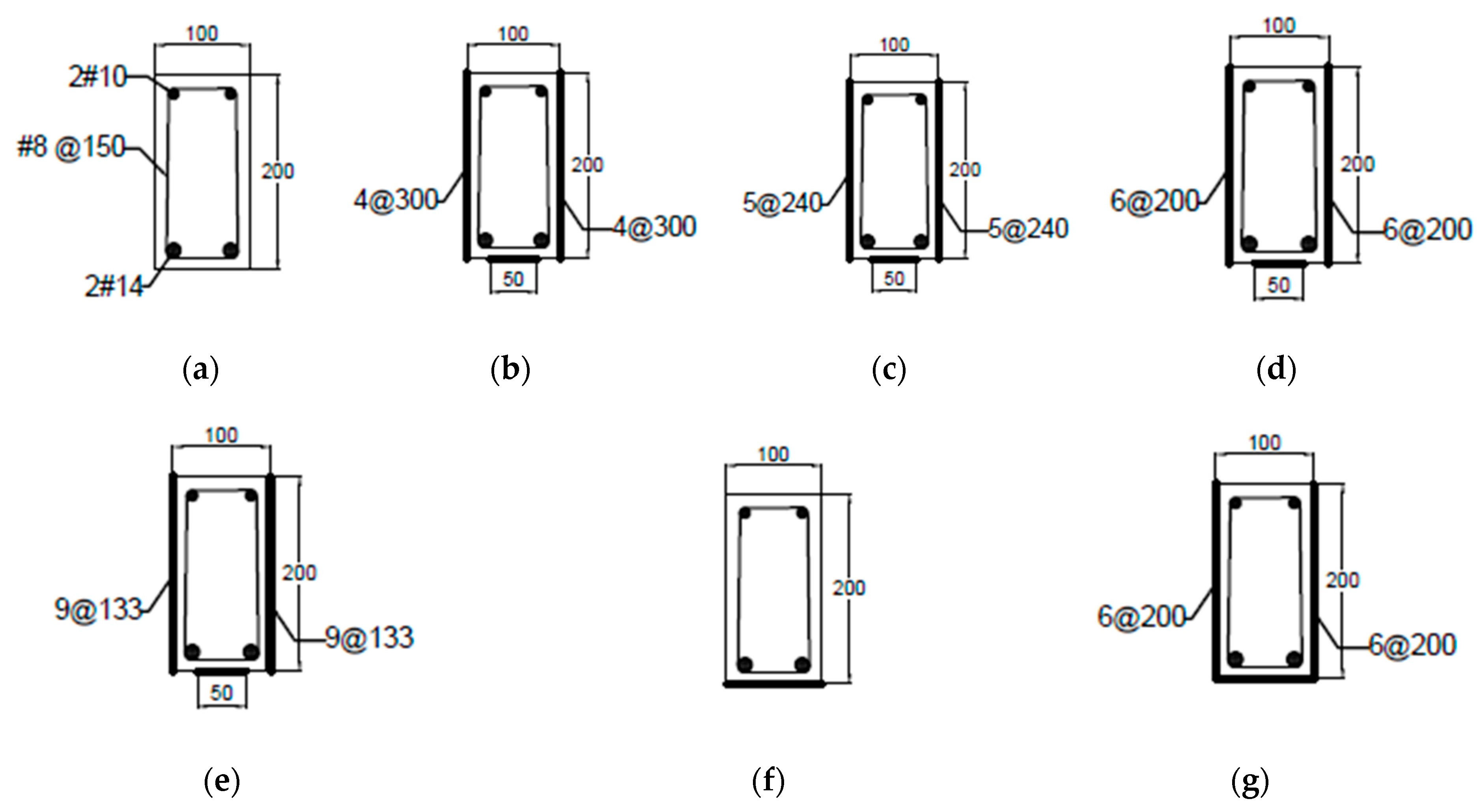
34] for tension controlled failure. Two deformed rebars of 14 mm nominal diameter were used as a flexural steel reinforcement.
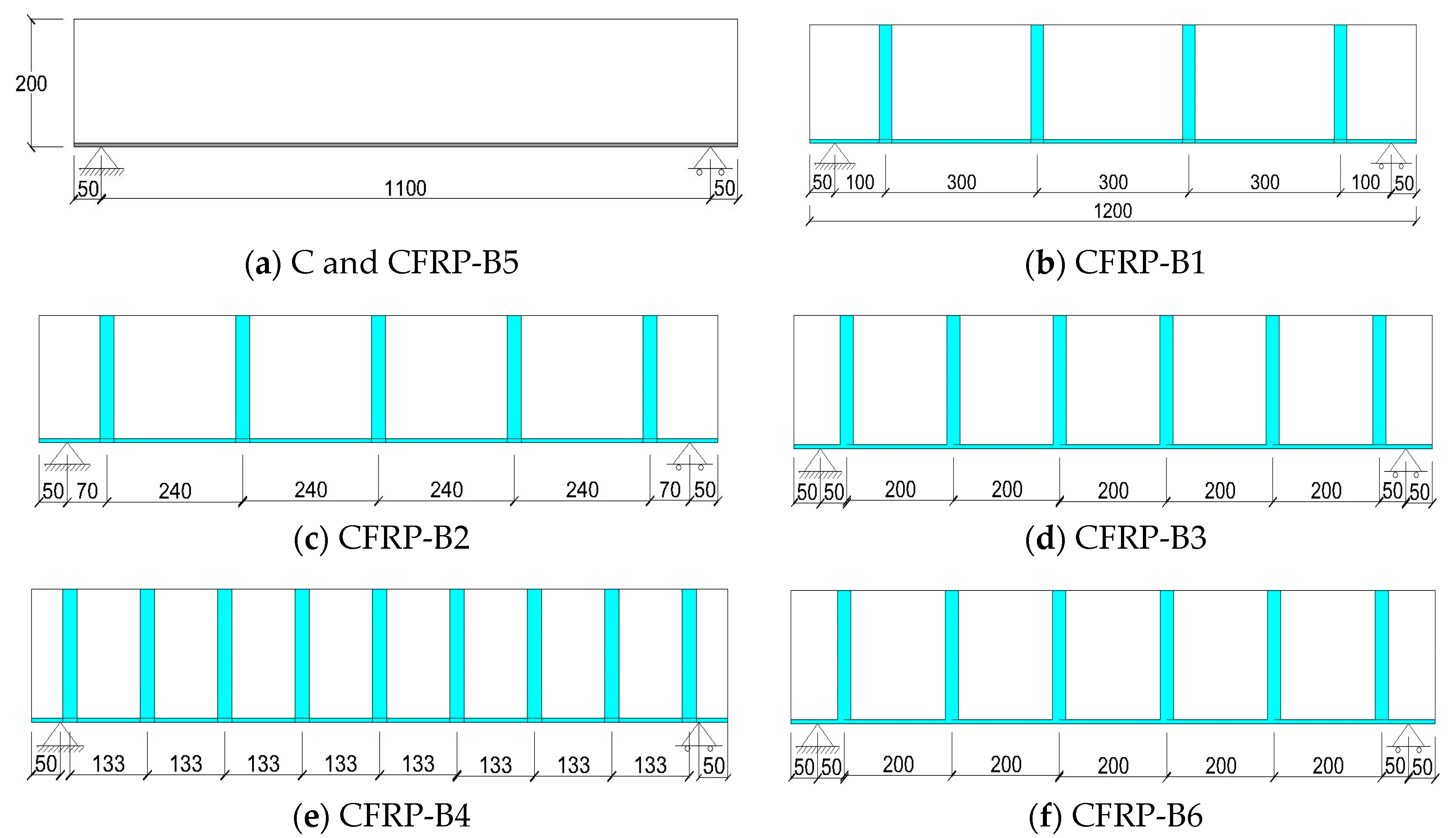
 Figure 1 and 
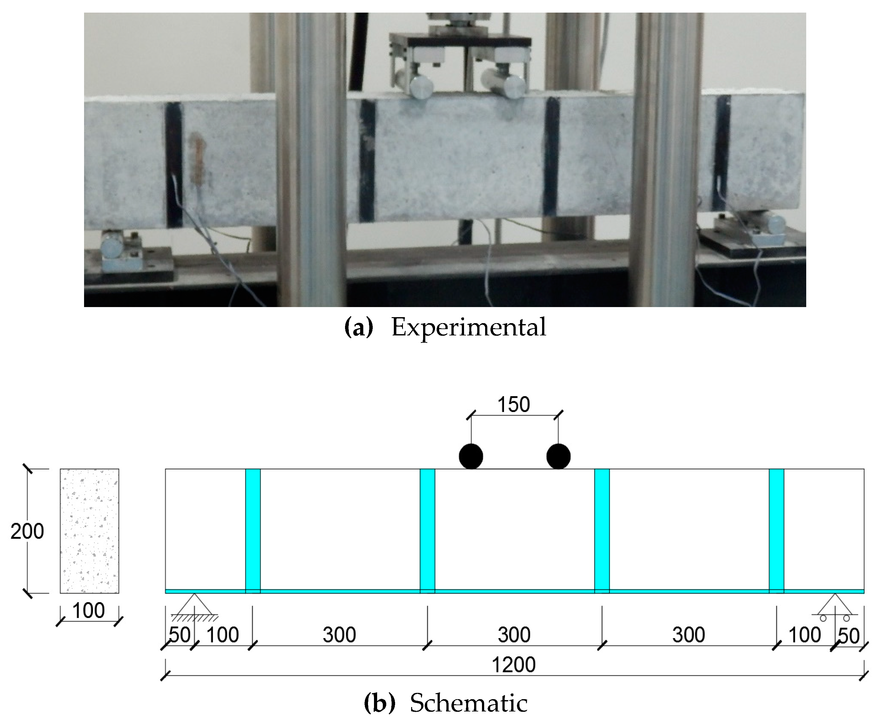
Figure 2 give the details of the beams tested under the current experimental plan. The load is applied under a displacement control system at a constant strain rate of 0.03/min. The bending setup located in highway laboratory of King Faisal University was used to carry out the experimental research work as shown in Figure 3. The beams were tested under four-point loading, which gives a constant mid-span bending moment for a given increment of load between the two loading points. Effective span in all beams was kept equal to 1100 mm. The applied bending moment M of the beam is calculated by Equation (1). As the moment between loading point remains constant, the Sagital Method was used to calculate the curvature φ by using mid-span deflection δ of the beam.
M = P 2 × L 1
where P is the load directly obtained from the Universal Testing Machine at each increment of displacement. L1 is the distance between the support and point of application of load = 475 mm and L is the effective span of the beam = 1100 mm, as given in Figure 3b.
One out of seven beams was selected as a control specimen, while the rest of the six beams were strengthened and retrofitted with external CFRP reinforcement ratios given in Table 1. The thickness of external flexure and shear CFRP strips was kept equal to 1.5 mm. For all beams, the cross-sectional sizes, internal reinforcement ratios, overall length, and thickness of CFRP strips were kept constant, while the external flexure and shear CFRP reinforcement ratios were varied. Table 1 shows the strengthening scheme of the beams, which were divided into two groups. Beams B1, B2, B3, and B4 were placed in group-1, where the external CFRP flexural reinforcement ratio was kept constant (0.38%). Beam B5 and B6 were placed in group-2, where the external CFRP flexural reinforcement ratio was doubled and kept equal to 0.75%. The flexural reinforcement ratio refers to the quantity of CFRP that is applied at the bottom surface of the beam. Reinforcement ratio is calculated by dividing the cross-sectional area of CFRP with the cross-sectional area of the concrete beam. In a similar way, the shear reinforcement ratio was calculated. Hence, the total CFRP reinforcement ratio is the sum of the flexural and shear CFRP reinforcement ratio. However, the external CFRP shear reinforcement ratio was also varied and was selected equal to 0 and 0.38% for Beam B5 and B6, as given in Table 1.

Material Properties

Concrete with a compressive strength of 28 MPa was used for the preparation of reinforced concrete beam specimens. The average compressive strength of concrete was determined by the procedure mentioned in ASTM C-39 [35] and was found equal to f c = 28   MPa . The modulus of elasticity and shear modulus of concrete were 24,870 MPa and 10,360 MPa, respectively. The modulus of elasticity of concrete was calculated using the ACI 318-08 [34] and shear modulus of elasticity was computed using poison ratio of 0.2. For quality control, the ready-mix concrete was delivered by a local supplier from a plant located in Saudi Arabia. For internal reinforcement, the yield strength of f y = 420   MPa was selected for deformed rebar. The steel reinforcement has a tensile rupture strength of 620 MPa with elastic and shear modulus values of 200,000 MPa and 76,920 MPa, respectively.
Concrete beam specimens were cast and cured as per ASTM-C31 [36]. On completion of curing time, the external surfaces of the beam specimens were cleaned with a wet cloth and acetone. Epoxy (Sikadur 330) of uniform thickness was used to attach external CFRP strips to the concrete surface. After the application of CFRP strips on the surface of the concrete, the beams specimens were cured for three days by using a wet layup method. Figure 1 and Figure 2 show the layout of beam specimens along with their external and internal reinforcement details. The CFRP has a tensile strength of 1600 MPa with the ultimate tensile elongation value of 1.8%. The tensile modulus of elasticity of CFRP was 120,000 MPa. The epoxy has tensile bond and compressive bond strength values of 9.6 MPa and 21 MPa, respectively. The aforementioned material properties of CFRP and epoxy were provided by their respective suppliers.

4. Results and Discussions

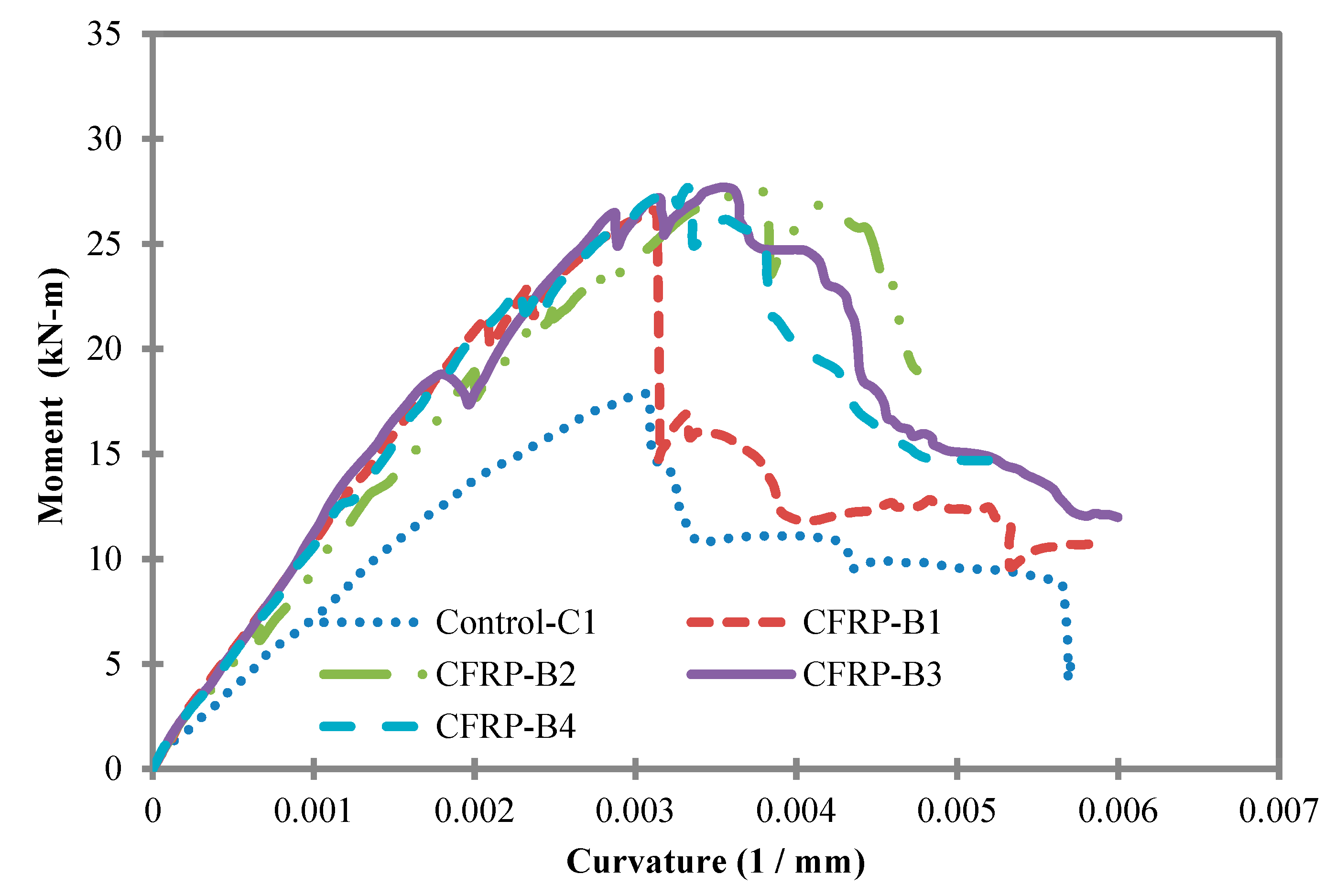
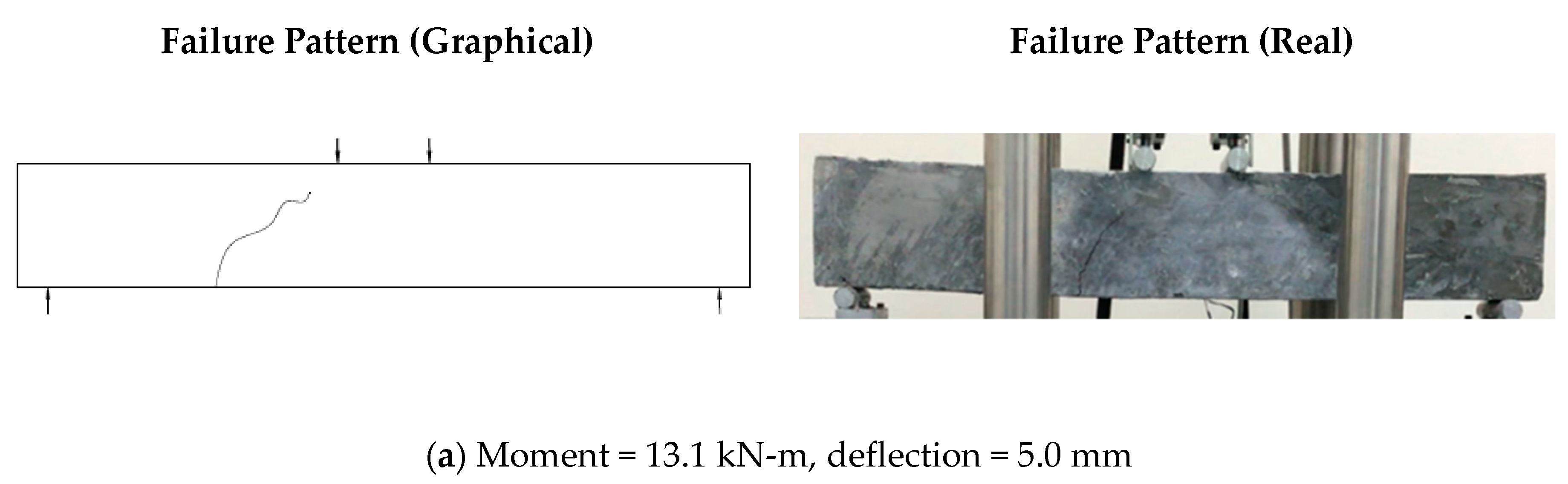
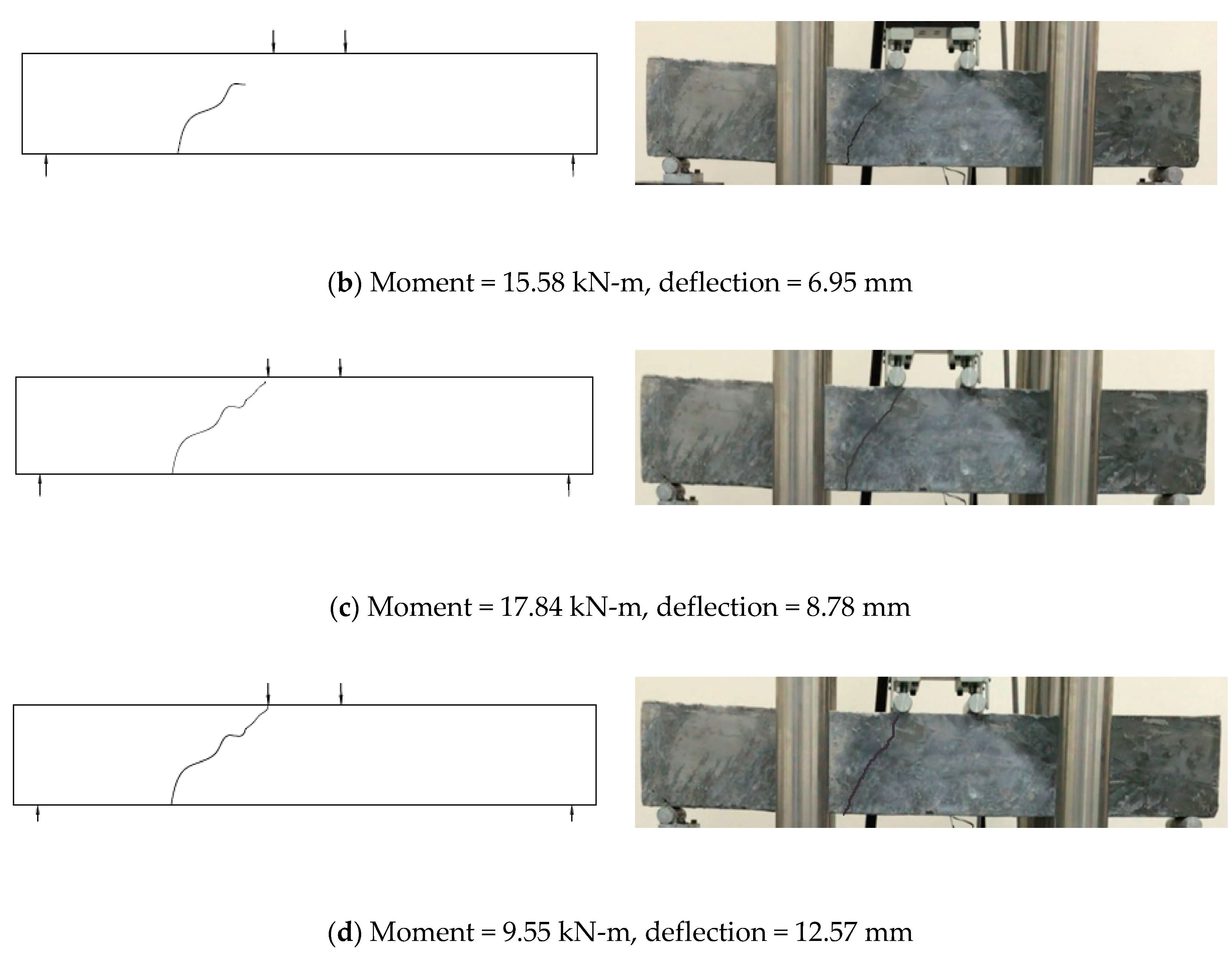
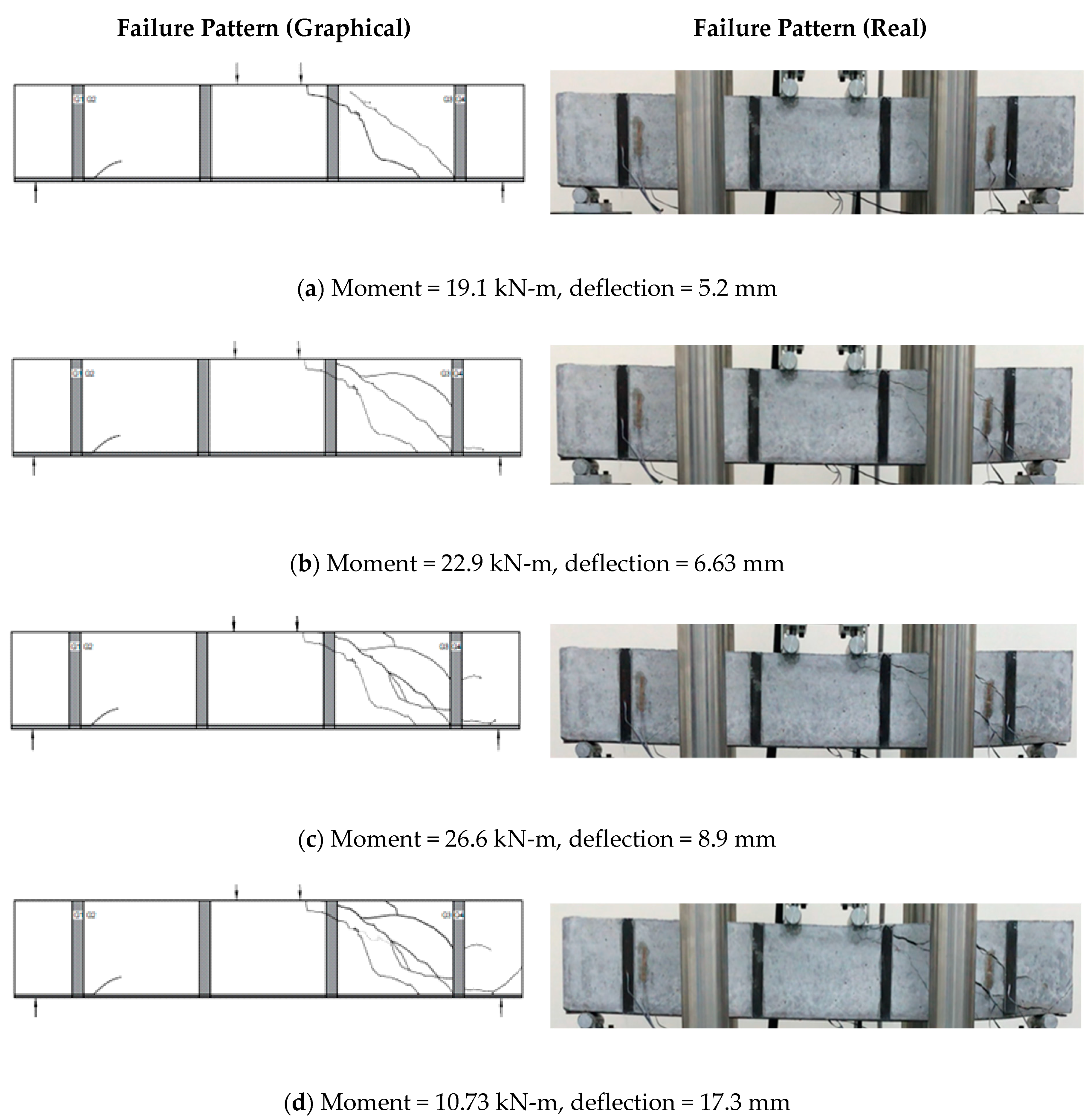
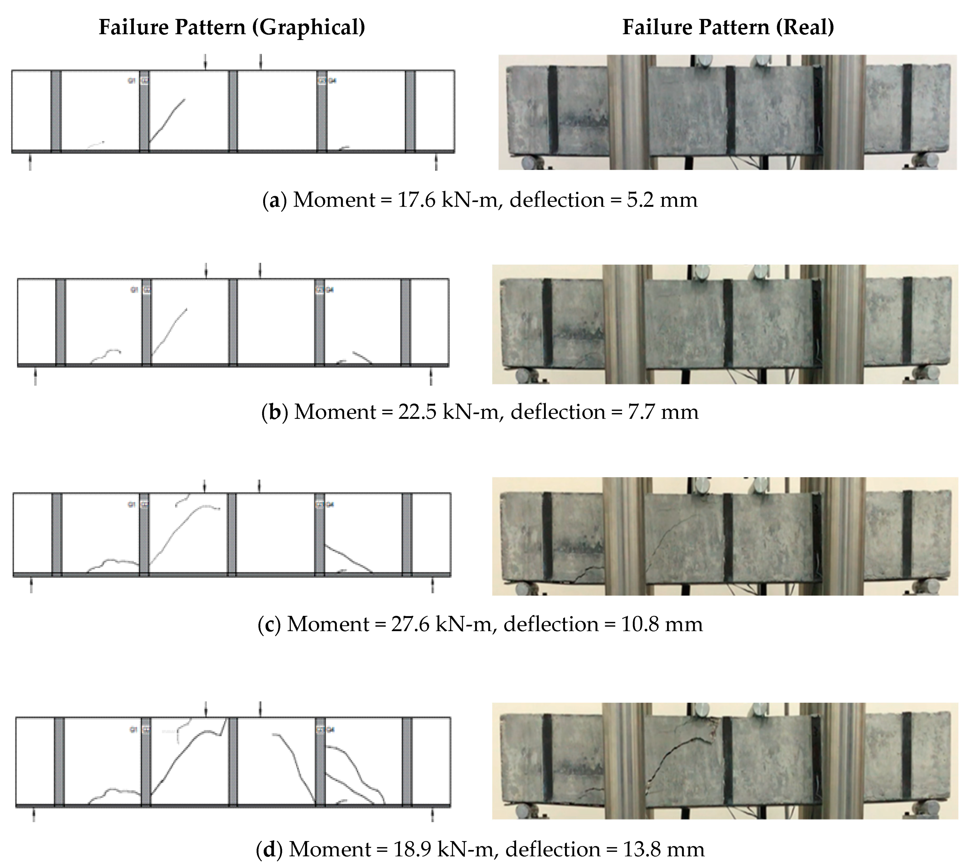
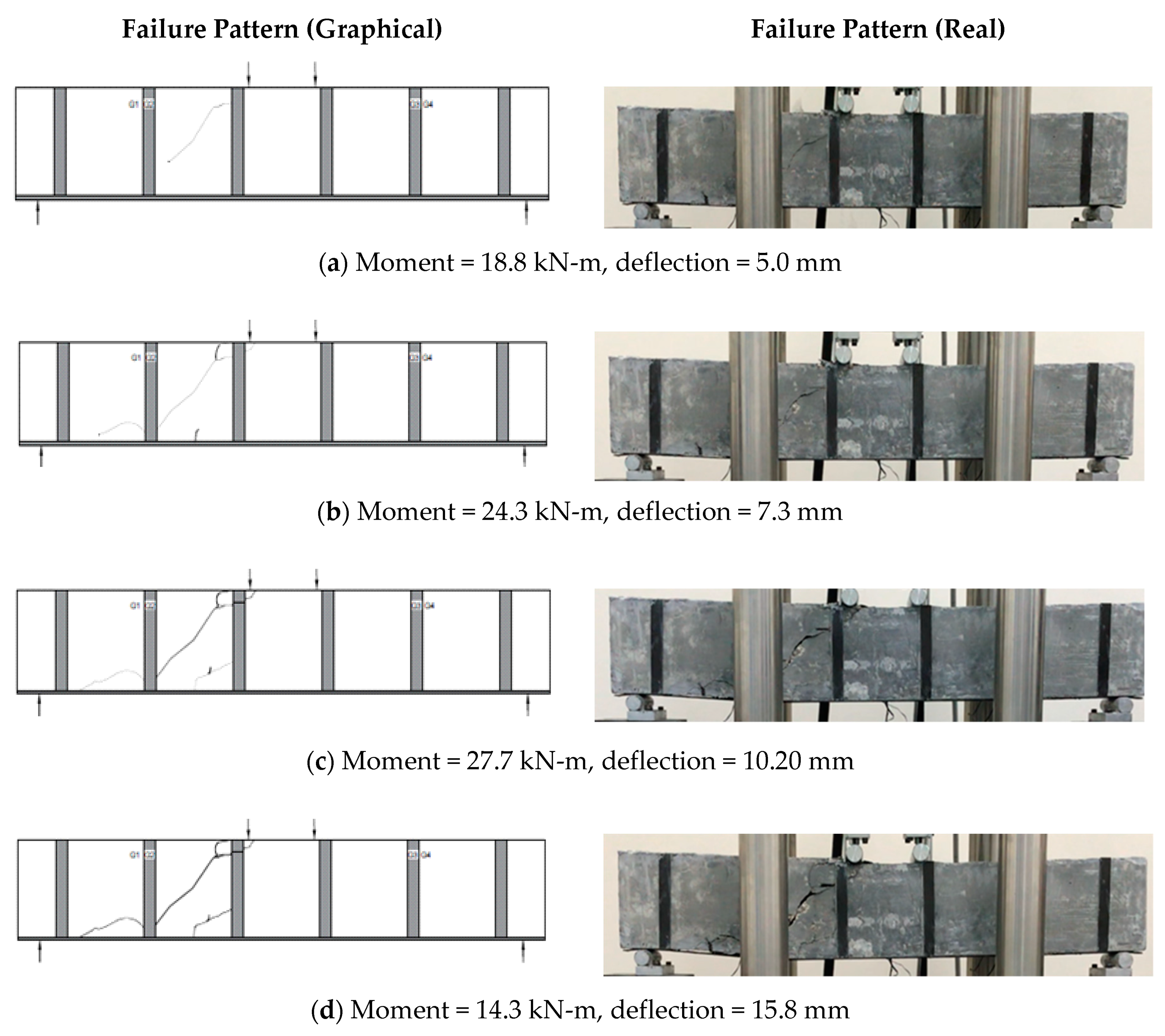
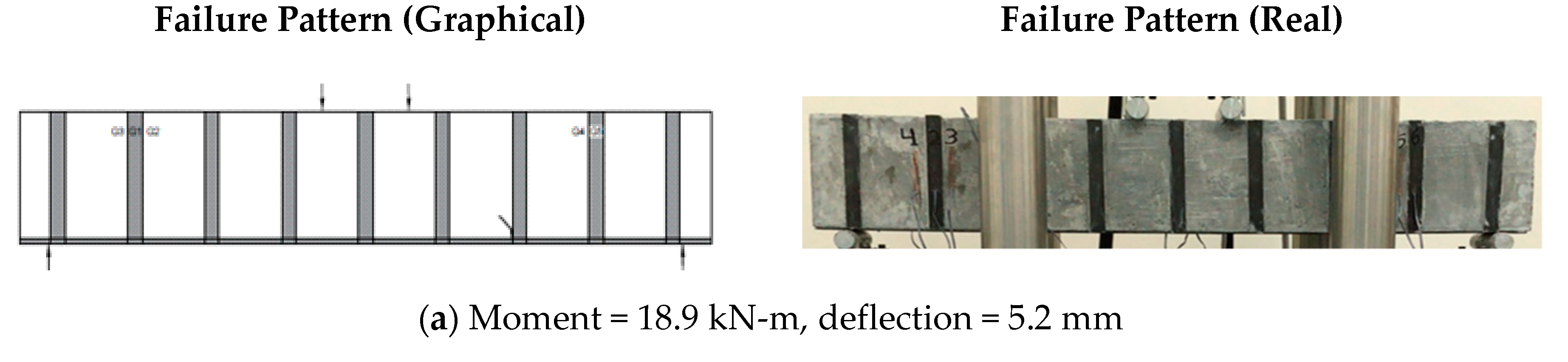
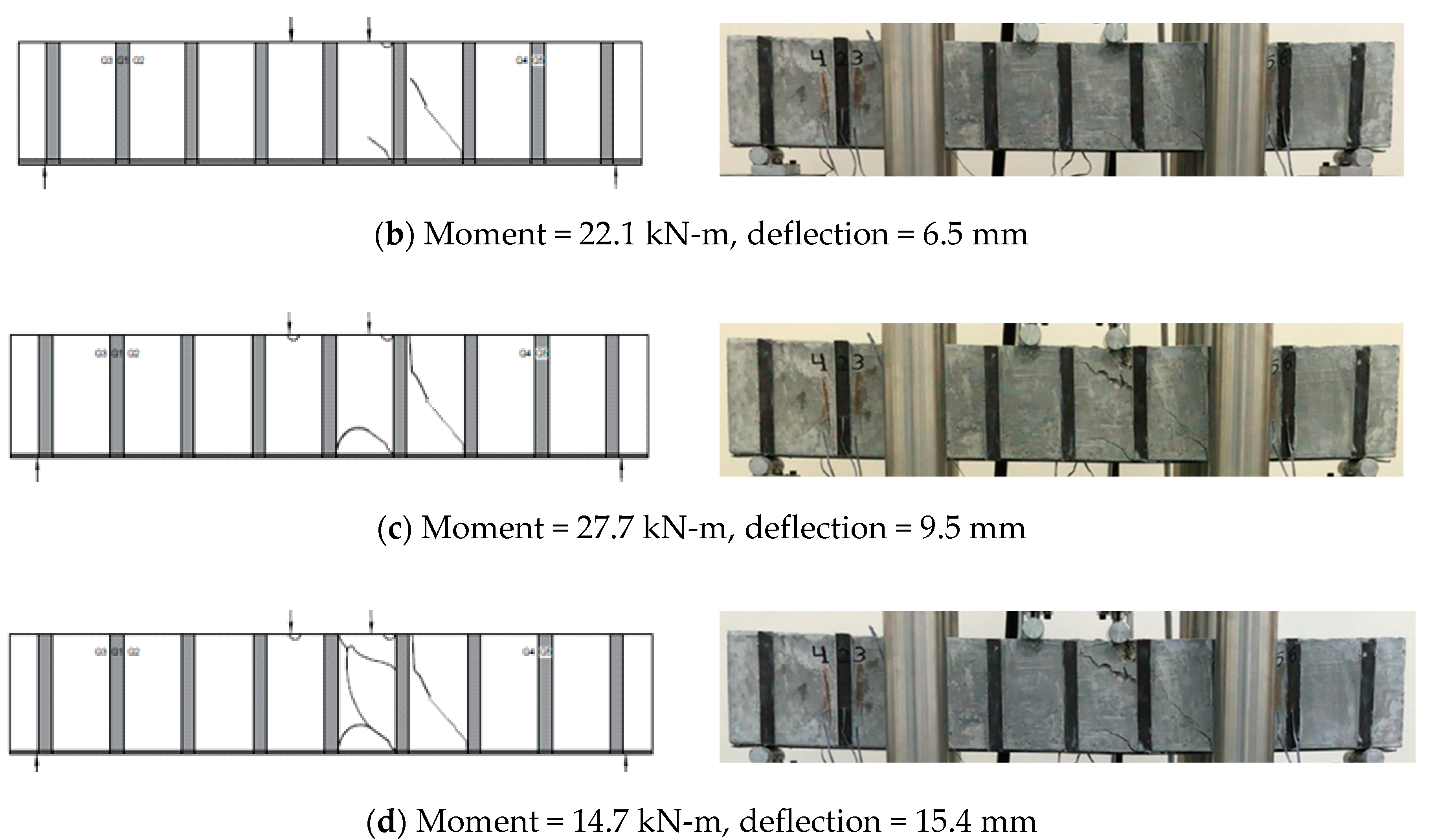
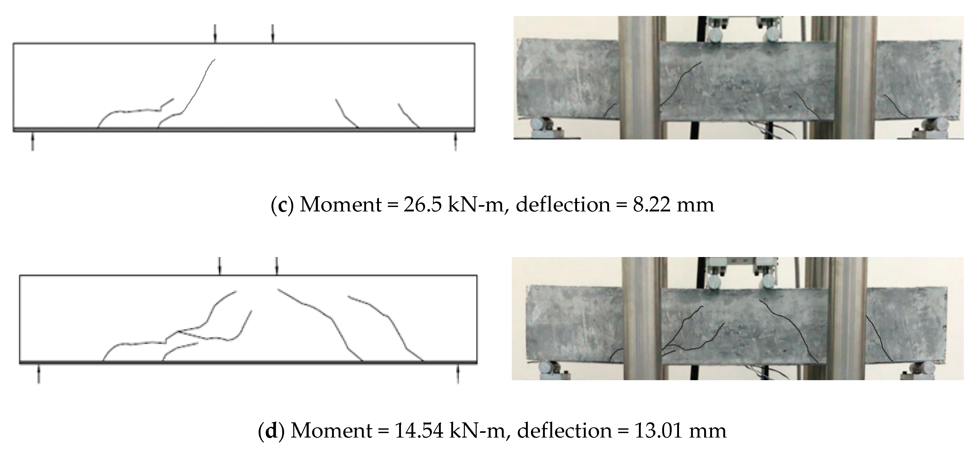
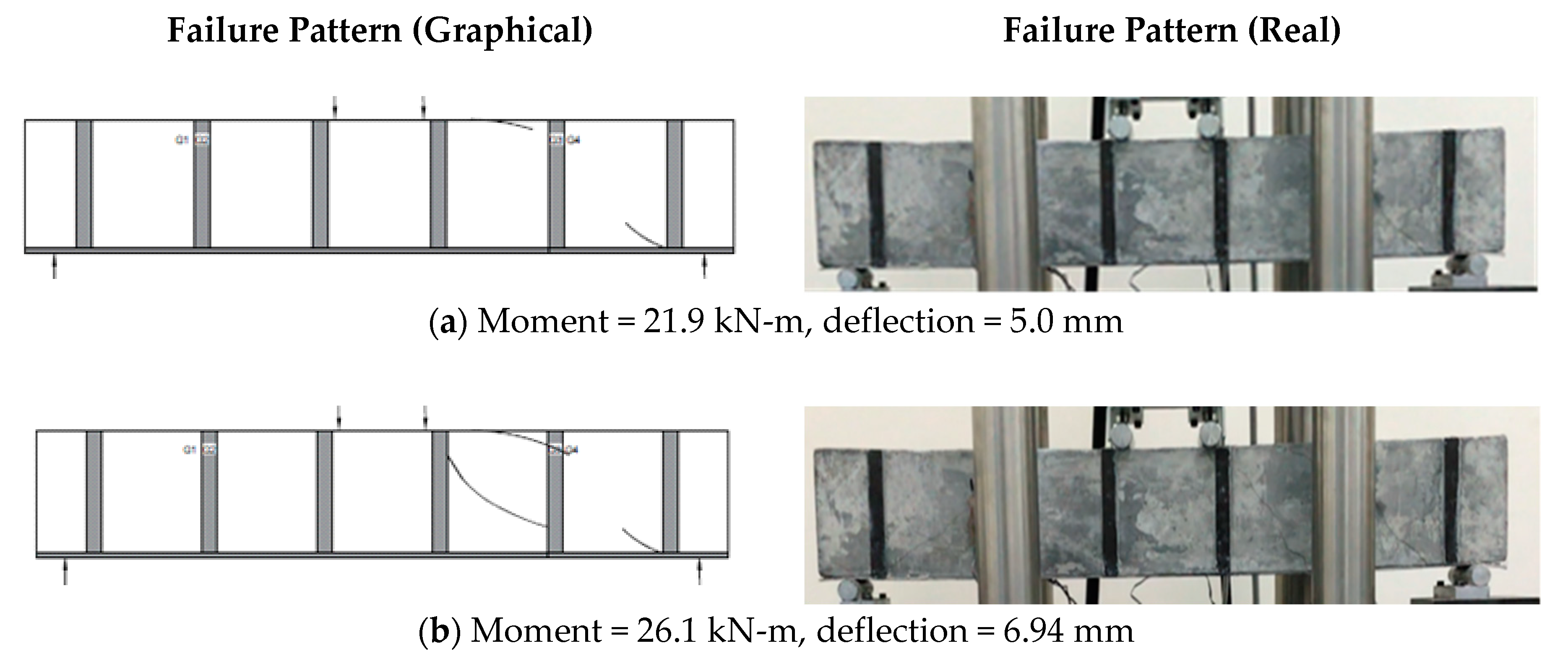
Figure 4 shows the mid-span bending moment-curvature behavior for the beam specimens C1, CFRP-B1, CFRP-B2, CFRP-B3, and B4, respectively. The control specimen has shown a peak moment value of 17.73 kN-m with the curvature value of 0.0031. Once the peak moment was reached, the control beam specimen C1 started losing its strength and finally, it reduced to 4.92 kN-m at a curvature value of 0.0057. The control specimen has shown a residual strength of 9.5 kN-m, which was approximately half of the peak strength (17.73 kN-m) of the control specimen. The residual strength of the concrete beam was mainly attributed to the cracked concrete section, which contains tensile reinforcement having a tensile strain greater than yield but lesser than the rupture strain. In the case of different CFRP strengthened beam specimens, higher peak moments were observed. The presence of CFRP strips has contributed to the flexural capacity and increased not only the peak strength but has also undergone higher displacements at the peak moment values. All of the beam specimens have shown peak strengths ranging from 27.7 kN-m to 26.6 kN-m. The maximum peak moment of 27.7 kN-m was observed in the case of beam CFRP-B4. All of the beams (CFRP-B1, B2, B3, and B4) carry a uniform external CFRP flexural reinforcement ratio of 0.38%, however, the shear reinforcement was gradually increased from 0. 25% to 0. 56%, respectively. The effect of this change in CFRP shear reinforcement ratio could be seen in the form of small variations in peak moment carrying capacities of the beams. For all of the beams, the relationship between curvature and moment capacities remained linear until the curvature value of 0.0017 was reached. After this value, the inelastic behavior of reinforced concrete became dominant and stiffness of the beam gradually started decreasing. All of the CFRP strengthened beams have shown a high residual strength compared to the control specimen C1. However, the highest residual strength was provided by specimen B3 and it was approximately 1.5 times the residual strength of the control specimen. Moreover, compared to the control specimen, the deformation capacities or curvature of the CFRP strengthened beams B1, B2, B3, and B4 were also higher. Beams B1, B2, B3, and B4 have shown a rise and fall in the moment values. This rise and fall behavior in the moment values represents the debonding of CFRP strips from the surface of the beam. After a small segment of CFRP strip was detached from the beam surface, a drop in strength occurred. With a further increase of load, the remaining bonded part of CFRP and concrete came into action and beams again started taking the load until the peak moment capacities of the beams was reached. Beam B1 has the minimum CFRP reinforcement compared to all other beams, and as a result, a sudden drop in strength was observed due to complete detachment of the CFRP strip from the concrete surface. As the beams were subjected to further load increments, the strength of beams B1, B2, B3, and B4 became equal to the control specimen. It showed that the contribution of CFRP reinforcement had completely gone and only reinforced concrete beam residual strength was in action.
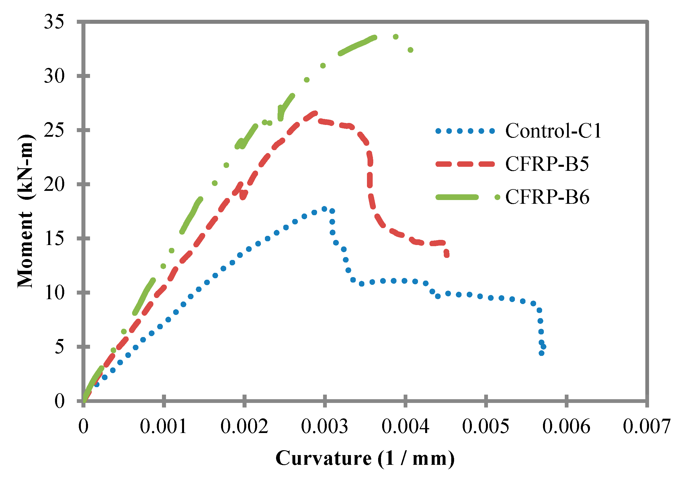
The mid-span bending moment-curvature behaviors of beam CFRP-B5 and CFRP-B6 and the control specimen C1 are given in 
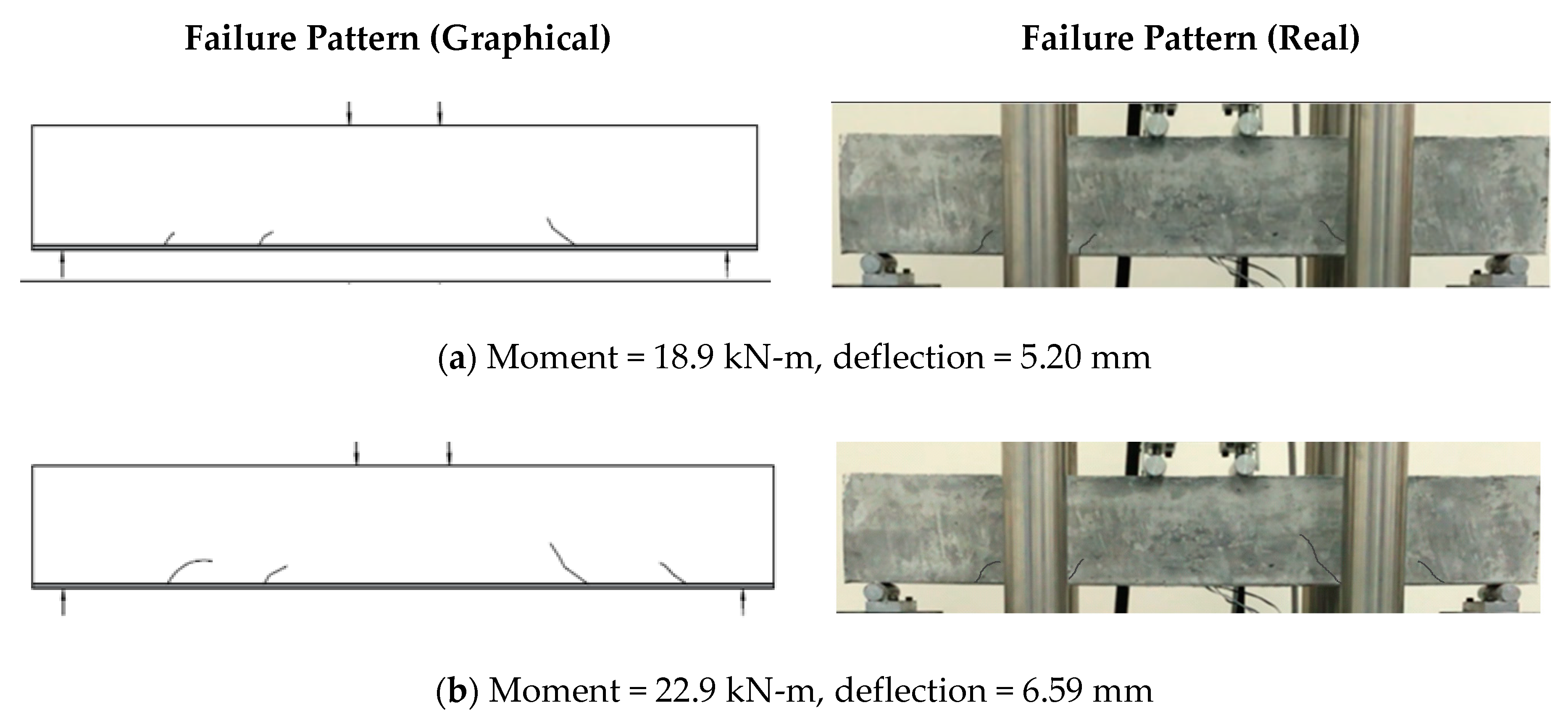
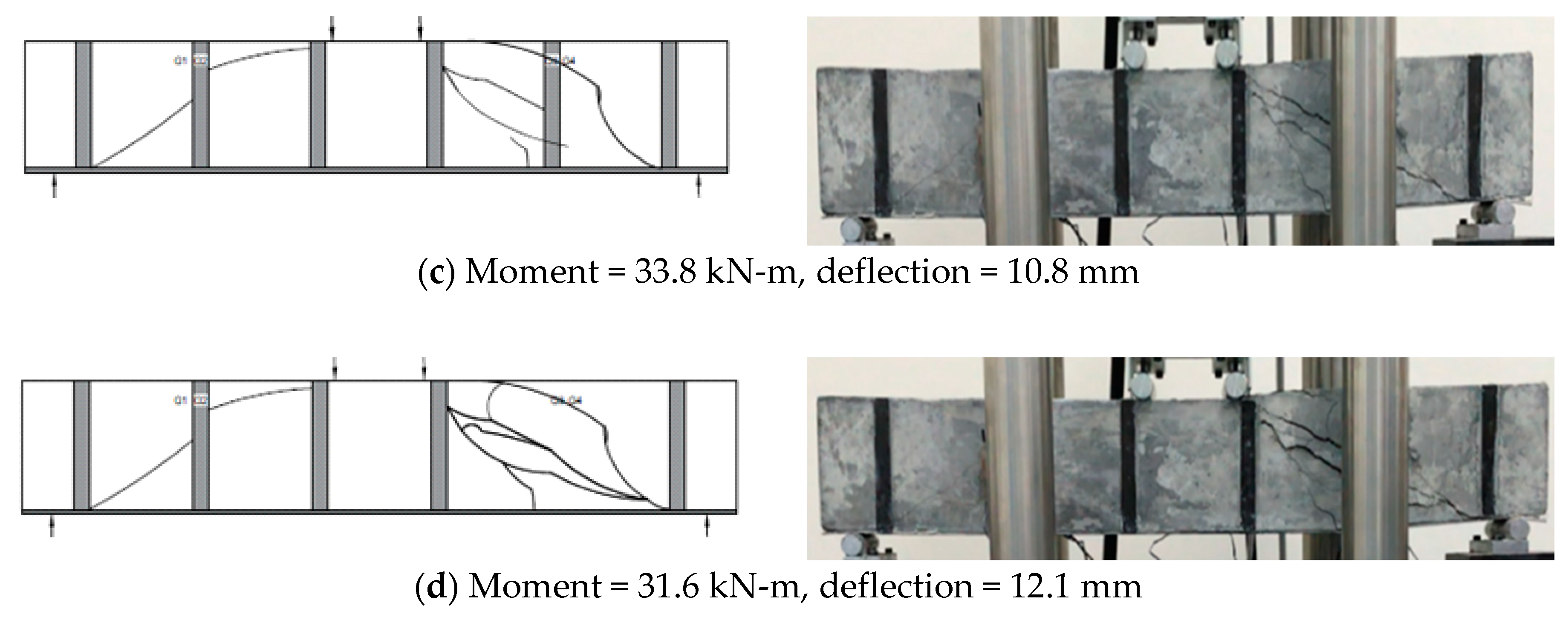
Figure 5. In the case of beam CFRP-B5 and CFRP-B6, the external CFRP flexural reinforcement was doubled compared to beam specimens CFRP-B1, B2, B3, and B4. Both beams B5 and B6 carry the same flexural reinforcement of 0.75%. However, beam B6 has a 0.38% shear CFRP reinforcement ratio, whereas beam B5 does not carry any shear reinforcement. Beam B5 has shown flexural strength of 26.52 kN-m that is 1.5 times higher than the peak strength of the control specimen (17.73 kN-m). On the other hand, beam B6 has shown a peak strength value of 33.71 kN-m, which is approximately double the strength of the control specimen. Adding 0.38% shear reinforcement ratio has increased the flexural strength from 26.62 to 33.71 kN-m. The presence of shear reinforcement hindered the diagonal shear crack propagation by intercepting their path, and in return, the moment carrying capacity of beam B6 has improved. The relation of moment-curvature remained linear prior to reaching the curvature values of 0.002. Beyond this value, a small rise and fall in the moment values was observed. These falls show the initiation of debonding failure between the CFRP and the concrete surface on the tension face of the beam.
Moreover, beam B6 has shown higher deformation or curvature compared to beam B5. For instance, the peak moment carrying capacity of the beam B5 occurred at a curvature value of 0.0028, whereas the peak strength of beam B6 was observed at a curvature value of 0.0038. It implies that the adding shear CFRP reinforcement in the presence of CFRP flexural reinforcement has not only increased the overall flexural strength of the beam but also the deformation capacity of the beam.
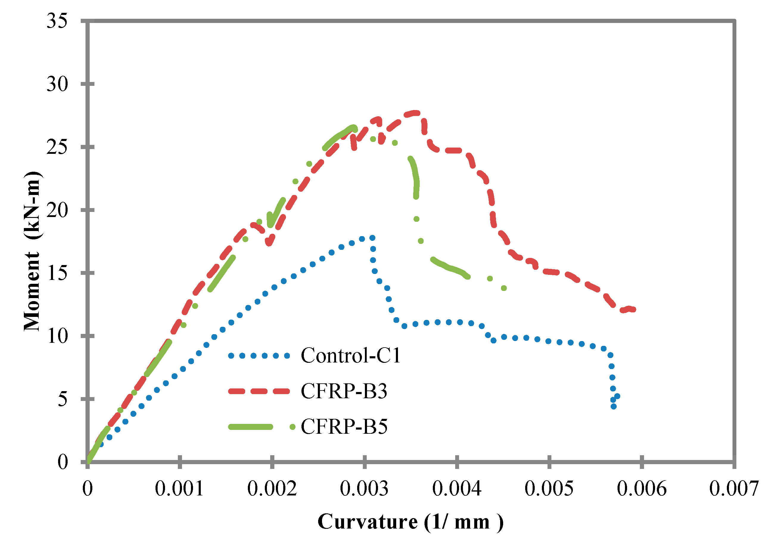
In order to understand the effect of shear reinforcement on the overall strength, a comparison of the mid-span bending moment-curvature behavior of beam CFRP-B3 and B5 is presented in Figure 6. Both beams CFRP-B3 and B5 carry an equal amount of overall (flexural plus shear) CFRP reinforcement ratio of 0.75%. However, in the case of beam B3, half (0.37%) of the total reinforcement (0.75%) was provided for flexure and the remainder was used for the shear. In the case of beam B5, the total reinforcement (0.75%) was provided as the flexural CFRP reinforcement, as given in Table 1. Beam B3 has shown peak strength of 27.7 kN-m compared to beam B5 that has a peak strength of 26.5 kN-m. Although a very small increase in overall strength was observed, beam B3 has shown better performance in terms of deformation capacity. Beam B5 has shown a curvature value 0.0028 at the peak moment of 26.5 kN-m and this was lower than the corresponding curvature value of 0.0035 for beam B3. For both beams, the debonding of CFRP from the tensile face started at the same curvature level, as indicated by a small fall in the moment at a curvature of 0.0019. However, the presence of shear strips provided resistance against shear cracks and improved the overall flexural behavior of beam B3. Moreover, beam B3 has shown better post-peak behavior compared to beam B5, as the residual strength of beam B3 was higher than beam B5.
The test results show that beams with higher CFRP shear reinforcement but with a lower amount of flexural CFRP reinforcement cannot contribute significantly in terms of the overall strength of the beam. For instance, group-1 beams had a lower flexural CFRP reinforcement ratio (0.38%) and the CFRP shear reinforcement was gradually increased from 0.25% to 0.56%. This increase in CFRP shear reinforcement ratio has increased the strength of beam B1 from 26.6 kN-m to 27.7 kN-m, which is not a significant contribution. On the other hand, when the flexural reinforcement doubled as in the case of the group-2 beam (B6), the moment carrying capacity increased to 33.8 kN-m.

5. Analytical Prediction of Beam Capacities

Several researchers compared the experimental and analytical flexural and shear capacities of different CFRP strengthened RC beams [21,22,23,24,25,26,27,28,29,30,31,32,37,38]. However, most of them [22,26,27,28,37] found close analytical values when ACI 440.2R-08 [33] was used. In the current study, ACI 440.2R-08 [33] was adopted to analytically obtain the flexural and shear capacities of the beams. The flexural strength of CFRP strengthened beams depends upon the governing mode of failure. Reinforced concrete beams strengthened with CFRP can experience three major failure modes: (i) tension failure of CFRP strip; (ii) debonding of CFRP from the concrete surface; and (iii) the crushing of concrete on the compression sides. ACI 440.2R-08 [33] considers all three failure modes to satisfy strain compatibility and force equilibrium conditions.
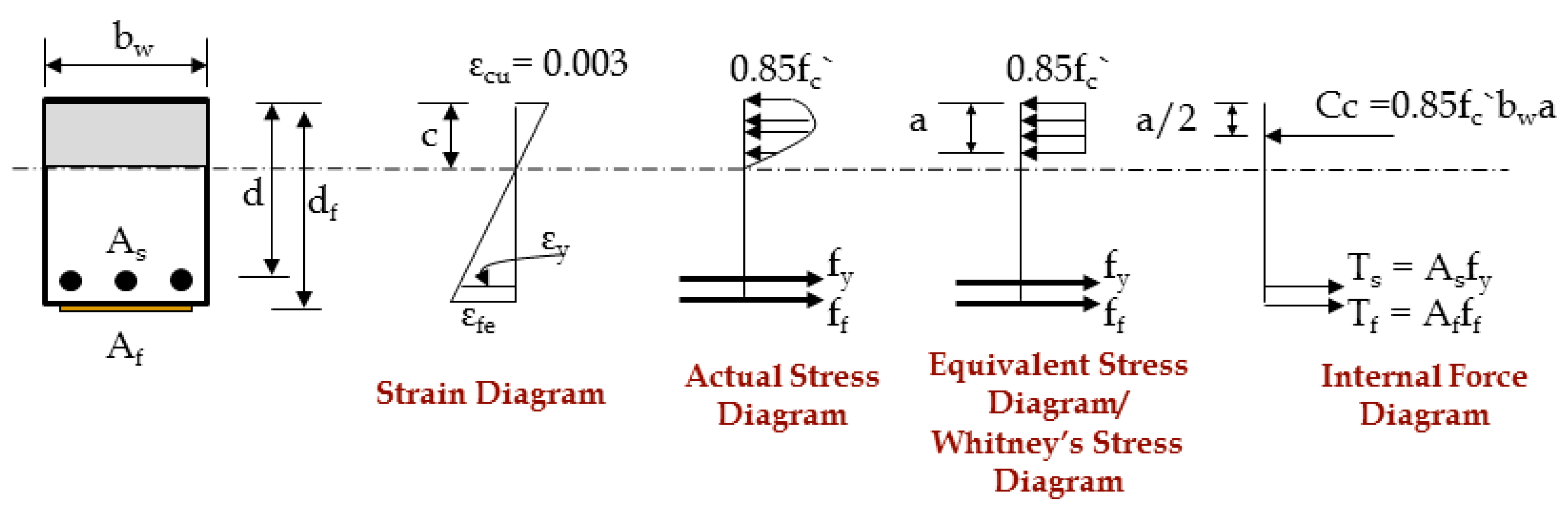
Figure 7 illustrates the internal strain and stress distribution of a CFRP strengthened rectangular RC beam under flexure. The ultimate nominal strength of beam (Mn) is obtained by satisfying strain compatibility and force equilibrium conditions and also considers the governing mode of failure. Equations (2)–(6) give the flexural or ultimate moment capacity of CFRP strengthened beams. In order to check the debonding failure of CFRP strengthened beams, the effective strain in the CFRP strips ( ε f ) should be limited to debonding strain level ( ε f d ), as given by Equation (4).
M n = A s f y ( d a 2 ) + A f f f ( d f a 2 )
ε f d = 0.41 f c n E f t f 0.9 ε f u
ε f = ε c u ( d f c c ) ε f d
f f =   ε f E f
a = β 1 c
According to ACI 440.2R-08, the shear strength of CFRP strengthened beams can be computed by Equation (7), as follows.
V n = V c + V s + Ψ f V f
where Vn is the nominal strength of a CFRP strengthened beam, Vs is shear strength provided by the steel and calculated by ACI 318-08 [34], as given by Equation (8), and Vc is the shear strength provided by the concrete, which can be computed by ACI 318-08 [34], as given by Equation (9).
V s = A v f y d s
V c = 0.17 f c b w d
where Vf is the shear strength provided by the CFRP shear strips and Ψ f = 0.85 is a reduction factor for CFRP shear strips applied on the sides of beams. ACI 440.2R-08 [
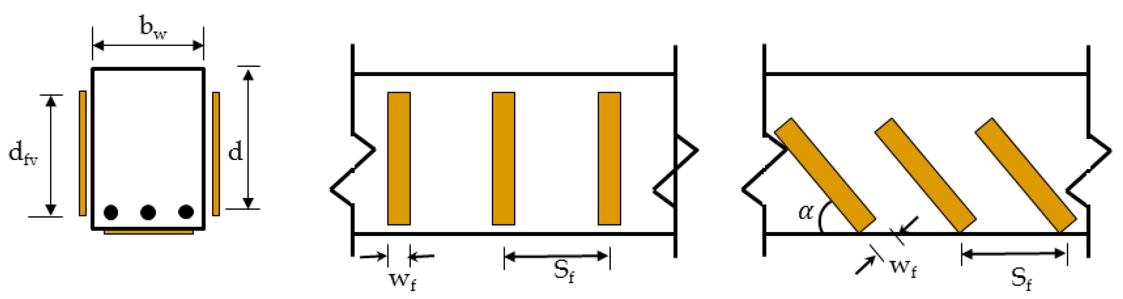
33] recommends Equation (10) to calculate the shear strength provided by the FRP strips. The effective stress in FRP and area of CFRP in shear can be calculated by using Equations (11) and (12), respectively. The dimensional variables used in Equations (10) and (12) can be seen in Figure 8.
V f = A f v f f e ( s i n α + c o s α ) d f v s f
f f e = ε f e E f
A f v = 2 n t f w f
For bonded face plies or CFRP strips, which is a strengthening system that does not enclose the entire section of the beam, failure of CFRP shear strips is mainly attributed to the delamination of CFRP from the concrete surface. Due to this reason, the bond stress was analyzed by Triantafillou [39] to determine the usefulness of these systems and proposed the effective strain level that can be achieved. The effective strain ( ε f e ) is calculated using a bond-reduction coefficient kv. Following Equations (13) and (14) gives the effective strain ( ε f e ) and bond-reduction coefficient kv. Equations (15)–(17) give the factors k1, k2, and effective length Le used in Equation (14).
ε f e = k v ε f u 0.004
k v = k 1 k 2 L e 11,900 ε f u 0.75
k 1 = ( f c 27 ) 2 / 3
k 2 = d f v 2 L e d f v
L e = 23,300 ( n t f E f ) 0.58
Table 2 gives a detailed comparison of analytical and experimental load-carrying capacities of the beam specimens. The control beam did not carry any flexural and shear CFRP reinforcement and its flexural and shear capacities were computed by ACI 318-08 [34]. The flexural and shear capacities of the CFRP strengthened beams are calculated by Equations (2) and (7), as recommended by ACI 440.2R [33]. The flexural capacity of the beam is the main function of the amount of CFRP applied at the tensile face of the beam. As beams B1, B2, B3, and B4 carry the same amount of CFRP flexural reinforcement ratio, these beams had the same analytical moment capacity of 25.35 kN-m. Similarly, beam B5 and B6 have the same analytical moment capacity of 33.41 kN-m. On the other hand, the shear capacity of the CFRP strengthened beams is proportional to the amount of CFRP shear reinforcement. Due to the different amounts of CFRP shear reinforcement, specimens B1 to B5 have different analytical shear capacities. However, beam B3 and B6 have the same CFRP shear reinforcement ratio and as a result, these have the same analytical shear capacities. From the analytical flexural and shear strengths of beams, their corresponding peak loads Pm for moment and Pv for shear are calculated and presented in Table 2. For instance, the analytical moment capacity of control beam 17.28 kN-m will result in the corresponding load capacity of ( P m = M n × 2 L 1 ) 72.8 kN. The analytical peak load of each beam is evaluated as the lesser of Pm and Pv, depending upon which type of failure will govern the ultimate load carrying capacity of the beam. In order to understand the effect of CFRP flexural and shear reinforcement, the control beam was designed to have the same flexural and shear capacity. However, the Pm for control beam was slightly lesser than the Pv and it suggests that the dominant mode of failure in the beam is flexural rather than shear, or it indicates that the flexural failure will occur first, followed by the shear failure of the beam specimen. Similarly, in the case of beams B1 to B4 and B6, flexural failure governed the overall design, and in the case of beam B5 the shear failure governed the peak load of the beam, as given in Table 2. A comparison of experimental and analytical peak loads has also been provided in the last column of Table 2. A very close agreement between analytical and experimental load values was achieved for all of the tested beams. In the case of beam B5, the difference is slightly more compared to the other beams. The experimental peak load of beam B5 was slightly higher compared to the analytical load. In reality, the CFRP flexural strip also contributes to the shear resistance of the beam, so to get closer analytical values requires an accurate prediction of CFRP flexural strip contribution in shear.

6. Cracking Behavior of Beams

6.1. Control Specimen C-1

Figure 9 shows the fracture behavior of control specimen C-1 at different load levels. Hairline cracks were observed prior to reaching a moment value of 8.7 kN-m and a displacement value of 3.5 mm. However, with an increase of moment from 8.7 kN-m to 13.1 kN-m, the crack started to propagate to the compression face of the beam, as shown in Figure 9a. With further increases in load, the crack further widened and became more prominent, as shown in Figure 9b. The cracks initially generated vertically at the bottom face of the beam and became inclined with an increase in the depth of the beam. It shows a flexural failure followed by the shear failure of the beam. A clear wide crack was observed prior to the failure of the beam at a moment and displacement level of 17.8 kN-m and 8.78 mm, respectively, as given in Figure 9c. After the peak moment capacity of 17.8 kN-m, the beam started losing its capacity and load values started decreasing, with a significant increase in the deformation capacity of the beam. No hairline cracks with uniform spacing were observed at the bottom section of the beam, which indicates the section was quite weak in strength. Figure 9d shows the failure pattern of a control specimen prior to the completion of the test. At the deflection level of 12.57 mm, a major wide crack was observed, which had split the beam into two distinct parts.

6.2. Beam CFRP B1

Failure patterns of beam CFRP B1 at different load levels are shown in Figure 10. In the case of beam B1, the initial minor cracks in the form of diagonal hairline cracks were spotted near the supports of the beam. These initial hairline cracks started to appear at a deflection value of 5.2 mm, as given in Figure 10a. With a further increase in the load, the beam started generating the new cracks and existing cracks were widened further, as shown in Figure 10b. As these cracks appear next to support in the form of diagonal movement, it confirms the shear dominant failure of the beams. The failure behavior of beam specimen B1 at the peak moment capacity of 26.6 kN-m and at a defection value of 8.9 mm is shown in Figure 10c. At a peak moment, cracks cross the FRP shear strip, however, due to higher shear forces, the existence of CFRP is not able to contribute much toward controlling the failure of the beam. Figure 10d presents the post-peak failure pattern of the beam at moment and deflection values of 10.73 kN-m and 17.3 mm, respectively. Beam B1 has only four CFRP shear strips on each face of the beam, with a higher spacing of CFRP shear strips. None of the CFRP shear strip intercepted the shear cracks initiated close to the right support of the beam. Therefore, the crack propagated diagonally to the compression face of the beam and resulted in the loss of beam strength. A significant amount of deflection and concrete crushing was observed close to the right support of the beam, which indicates that the bearing resistance of the beam was reduced and the concrete was finally crushed.

6.3. Beam CFRP B2

Figure 11 shows the failure patterns of beam CFRP B2 at different load levels. Beam B2 carries a CFRP flexural reinforcement ratio of 0.38%, which was similar to beam B1, however, the CFRP shear reinforcement of beam B2 (0.31%) was slightly higher than beam B1 (0.25%). As a result, beam B2 carries five CFRP strips on each face of the beam, as shown in Figure 11. At a deflection value of 5.2 mm, no significant cracks were observed, however small hairline cracks were observed close to the left support of the beam, as shown in Figure 11a. A similar kind of pattern was noticed when the load on beam B2 was further increased until the mid-span deflection became equal to 7.7 mm, as given in Figure 11b. With a further increase in load, the cracks not only propagated diagonally but also became wide and visible to the naked eye. Figure 11c gives the cracking pattern of beam B2 at the peak moment capacity of 27.6 kN-m. Once the peak moment was reached, beam B2 started losing its capacity and cracks became more widespread and visible. In the case of beam B2, flexural mode of beam failure was dominant. Prior to complete failure, the diagonal crack reached the compression face of the beam and at that point, the beam had a residual moment carrying capacity of 18.9 kN-m, as shown in Figure 11d.

6.4. Beam CFRP B3

The graphical and experimental failure patterns of beam B3 are shown in Figure 12. In the case of beam B3, the shear reinforcement has been increased compared to beam B2, while the external CFRP flexural reinforcement was kept similar to beam B1 and B2. In beam B3, six shear strips were provided on each face of the beam, as shown in Figure 12. At a deformation level of 5 mm, a moment capacity of 18.8 kN-m was observed, which was greater than the moment capacities of beam B1 and B2, respectively. No significant number of cracks were observed in the case of beam B3, as shown in Figure 12a. When the load was further increased, very small hairline cracks were observed on the beams, as given in Figure 12b. Beam B3 showed better behavior compared to beam B1 and B2 at the deformation level of 7.3 mm. Figure 12c shows the failure behavior of the beam at the peak moment carrying capacity of 27.7 kN-m. At a peak load, the beam underwent a significant level of cracking and slight crushing of the concrete was also observed. It shows a flexural failure due to the crushing of concrete. However, the crack remained confined between the two FRP strips. The major cracks were spotted near the left part of the beam. Figure 12d shows the post peak-cracking pattern of beam B3. The residual strength of beam B3 was close to beam B2; however, the cracks remained restricted between two CFRP shear strips.

6.5. Beam CFRP B4

Figure 13 shows the graphical and experimental failure patterns of beam B4 at different load levels. In the case of beam B4, the CFRP shear reinforcement ratio was increased to 0.56% compared to beam B3 (0.38%), which resulted in a total of nine CFRP shear strips on each face of the beam. Figure 13a shows no significant cracks at a deflection value of 5.2 mm. However, when the load was slightly increased, it resulted in the formation of very small flexural and shear cracks near the mid-span of the beam, as given in Figure 13b. Beam B4 showed a peak moment capacity of 27.7 kN-m, which is similar to the moment capacity of beam B3. At the peak load level, the flexural cracks became more prominent and wider, as shown in Figure 13c. However, these cracks remained confined to the two CFRP shear strips. The cracks were also very steep compared to beam B1, B2, and B3, respectively. Figure 13d shows the cracking behavior of the beam at a deflection value of 15.4 mm. At this load level, the cracks passed through the CFRP shear strips and resulted in debonding of the shear strips from the concrete surface.

6.6. Beam CFRP B5

In beam B5, the amount of flexural reinforcement was doubled compared to beam B1, B2, B3, and B4. However, beam B5 did not contain any external CFRP shear reinforcement. Figure 14a–d presents the graphical and experimental cracking patterns of beam B5 at different load and deflection levels. A small number of cracks were observed at a deflection level of 5.2 mm (Figure 14a), which later on further increased in length and thickness when the deflection value reached 6.59 mm, as given in Figure 14b. These cracks were a mix of Mode-1 (flexural) and Mode-2 (shear) cracks, as they resulted from the interaction of bending and shear. Beam B5 has shown a peak moment capacity of 26.5 kN-m, which was greater than control beam but less than the other beams, such as B1, B2, B3, and B4, respectively. Prior to the peak moment capacity of 26.5 kN-m, a debonding type of failure of CFRP from the concrete surface was also observed. Figure 14c shows a significant number of cracks in beam B5, which were considerably wider in nature compared to the cracks that occurred at the deflection value of 6.59 mm. These cracks became even wider and longer when the deflection was increased and reached a value of 13.01 mm (Figure 14d).

6.7. Beam CFRP B6

Figure 15 shows the failure pattern of beam B6, which contains both flexural and shear CFRP reinforcement. The flexural reinforcement of beam B6 was similar to beam B5 (0.75%), with a shear reinforcement ratio of 0.38%. Like other beams, no significant cracks were observed at a deflection value of 5.0 mm, as shown in Figure 15a. With a further increase in load and deflection value, small hairline cracks started appearing closer to the beam support. Figure 15b shows that these cracks were shear in nature and occurred at a deflection value of 6.94 mm. Beam B6 showed a maximum peak strength moment capacity of 33.8 kN-m at a deflection value of 10.8 mm. At this peak point, some of the CFRP strips were de-bonded from the concrete surface and the cracks further moved diagonally. Although these cracks were intercepted by the shear CFRP strips, CFRP shear strips could not hinder their propagation in the diagonal direction, as given in Figure 15c. The final failure of the beam was mainly due to the crushing of concrete in the compression side of the beam. The post-peak cracking pattern of beam B6 is presented in Figure 15d. Beam B6 has shown a residual strength of 31.6 kN-m at a deflection level of 12.1 mm. At a deflection value of 12.1 mm, one of CFRP shear strips was completely de-bonded and fell apart.

7. Conclusions

In this research study, a series of four-point bending tests were carried on reinforced concrete beams which were strengthened with different amounts and layouts of external CFRP flexural and shear reinforcement ratios. The layout of the CFRP application and the CFRP reinforcement ratio were the main parameters of the research study. Effects of these parameters were studied in terms of moment-curvature values, ultimate load carrying capacities, and failure patterns of the beams. A comparison between experimental and analytical ultimate load carrying capacities of the beams is also presented in this research study. The reinforced concrete beams were divided into two groups. Beams in group 1 had a CFRP flexural reinforcement ratio half of that of group 2 beams. However, the CFRP shear reinforcement was gradually increased in the reinforced concrete beams. Based on the results obtained from the experimental study, the following major conclusions are summarized.
  • The choice of CFRP flexural reinforcement can influence the failure mode and strength gain of the RC beams. The ultimate load carrying capacities and the deformation capacities of the beams can increase to a certain level by increasing flexural or shear CFRP reinforcement. For this reason, a better understanding of beam governing mode of failure is necessary. For instance, a beam which is over-reinforced in flexure may result in the shear failure of the beam.
  • Increasing the external CFRP shear reinforcement in reinforced concrete beams that have less flexural reinforcement did not result in a significant increase in strength. It was also observed that increasing CFRP flexural reinforcement in absence of external CFRP shear reinforcement did not result in a significant increase in strength.
  • It was noted that the failure modes of the beams were highly dependent on the CFRP reinforcement layout. For the beams that had higher spacing between CFRP shear strips or no shear reinforcement, the failure occurred near the supports, in terms of diagonal shear cracks having a smaller angle of occurrence. On the other hand, for the beams that had smaller spacing between CFRP shear strips, the cracks that appeared were found to be steep and remained confined within the CFRP shear strips. The presence of CFRP shear strips hindered crack propagation, as well as resisted beam deformations.
  • The flexural failure of the beams was initiated due to debonding of CFRP strips from the tensile face of the beams. The delamination of CFRP flexural strips started from the mid-span of the beam and moved laterally to the support, proving a bearing failure of the beam.
  • The analytical procedure proposed by ACI R440.2-08 [33] was used to predict the moment and shear capacities of simply supported CFRP strengthened beams and a good agreement between the experimental and analytical ultimate load carrying capacities of the beam was obtained. Therefore, ACI 440.2R-08 [33] can be effectively used for the design and evaluation purposes of CFRP strengthened reinforced concrete beams.

Author Contributions

The most significant contributions in this research study were made by M.U.S. and H.J.Q. The experimental scheme of the research study was planned by M.U.S. and H.J.Q., M.N.A., K.K., and H.K. prepared the beam specimens and also cured the beams at later stages. M.U.S., H.J.Q., M.N.A., and K.K. tested the specimens and collected the data. Results were prepared and analyzed by M.U.S., H.J.Q and M.N.A. The original draft was prepared by M.U.S., H.J.Q., and H.K. The review and editing were later carried out by M.U.S. and H.J.Q.

Funding

This research was supported by the Deanship of Scientific Research (DSR) at King Faisal University (KFU) through its “Eighteenth annual research project no. 180061”.

Acknowledgments

This research was supported by the Deanship of Scientific Research (DSR) at King Faisal University (KFU) through its “Eighteenth annual research project no. 180061”. Authors are thankful to the Deanship of Scientific Research, King Faisal University for supporting this entire research study. In particular, authors are thankful to the Dean of Scientific Research, King Faisal University, who provided a lot of administrative support for the successful completion of this research project.

Conflicts of Interest

Authors reserves the complete right of the data and declare no conflict of interest with any private and public sector body.

Abbreviations

Afarea of FRP external reinforcement, (mm2)
Afvarea of FRP shear reinforcement with spacing, (mm2)
Asarea of non-prestressed steel reinforcement, (mm2)
adepth of Whitney’s stress diagram, (mm)
bwweb width or diameter of circular section, (mm)
cdistance from extreme compression fiber to the neutral axis, (mm), c = 3/8 d for tension controlled failure of beams
ddistance from extreme compression fiber to centroid of tension reinforcement, (mm)
dfeffective depth of FRP flexural reinforcement, (mm)
dfveffective depth of FRP shear reinforcement, (mm)
Eftensile modulus of elasticity of FRP, (MPa)
f c specified compressive strength of concrete, (MPa)
ffeffective flexural stress in the FRP; stress level attained at section failure, (MPa)
ffeeffective shear stress in the FRP; stress level attained at section failure, (MPa)
fyspecified yield strength of non-prestressed steel reinforcement, (MPa)
hoverall thickness or height of a member, (mm)
k1modification factor applied to κv to account for concrete strength
k2modification factor applied to κv to account for wrapping scheme
Leactive bond length of FRP laminate, (mm)
Mapplied moment using testing machine
Mnnominal flexural strength, (N-mm)
nnumber of or strips of FRP reinforcement
Pmpeak load of the beam calculated from nominal moment capacity of the beam
Pvpeak load of the beam calculated from nominal shear capacity
Papeak load of the beam determined analytically
Pepeak load of the beam determined experimentally
tfnominal thickness of one ply of FRP reinforcement, (mm)
Vcnominal shear strength provided by concrete with steel flexural reinforcement, (N)
Vfnominal shear strength provided by FRP stirrups, (N)
Vnnominal shear strength, lb (N)
Vsnominal shear strength provided by steel stirrups, (N)
wfwidth of FRP reinforcing plies, (mm)
β1ratio of depth of equivalent rectangular stress block to depth of the neutral axis for f c = 28 MPa, β1 = 0.85
εcuultimate axial strain of unconfined concrete corresponding to 0.85fc′ or maximum usable strain of unconfined concrete (mm/mm), which can occur at 0.85fc′ or 0.003, depending on the obtained stress-strain curve
εfddebonding strain of externally bonded FRP reinforcement, (mm/mm)
εfEffective flexural strain level in FRP reinforcement attained at failure, (mm/mm)
εfeeffective shear strain level in FRP reinforcement attained at failure, (mm/mm)
εfudesign rupture strain of FRP reinforcement, (mm/mm)
κvbond-dependent coefficient for shear
ψfFRP strength reduction factor, 0.85 for shear (based on reliability analysis) for three-sided FRP U-wrap or two-sided strengthening schemes
δmid span deflection of beam
φcurvature of the beam

References

  1. Sulaimani, G.J.; Shariff, A.; Basanbul, I.A.; Baluch, M.H.; Ghaleb, B.N. Shear repair of reinforced concrete by fiber glass plate bonding. Aci Struct. J. 1994, 91, 458–464. [Google Scholar]
  2. Chajes, M.J.; Jansuska, T.F.; Mertz, D.R.; Thomson, T.A.; Finch, J.R. Shear strength of RC beams using externally applied composite fabrics. Aci Struct. J. 1995, 92, 295–303. [Google Scholar]
  3. Chen, J.F.; Teng, J.G. Shear capacity of FRP strengthened RC beams: FRP debonding. Constr. Build. Mater. 2003, 17, 27–41. [Google Scholar] [CrossRef]
  4. Deniaud, C.; Cheng, J.J.R. Simplified shear design method for concrete beams strengthened with fiber reinforced polymer sheets. J. Compos. Constr. 2004, 8, 425–433. [Google Scholar] [CrossRef]
  5. Eshwar, N.; Nanni, A.; Ibell, T.J. Performance of two anchor systems of externally bonded fiber-reinforced polymer laminates. Aci Mater. J. 2008, 105, 72–80. [Google Scholar]
  6. Saleem, M.U.; Numada, M.; Amin, M.N.; Meguro, K. Shake Table Tests on FRP Retrofitted Masonry Building Models. J. Compos. Constr. 2016, 20, 1–19. [Google Scholar] [CrossRef]
  7. Takewaka, K.; Khin, M. Deterioration and stress rupture of FRP rods in alkaline solution simulating a concrete environment. In Proceedings of the 2nd International Conferences on Advanced Composite Materials in Bridges and Structures, Winnipeg, QC, Canada, 11–14 August 1996. [Google Scholar]
  8. Sen, R.; Shahawy, M.; Rosas, J.; Sukumar, S. Durability of aramid pretensioned elements in a marine environment. Aci Struct. J. 1998, 95, 578–587. [Google Scholar]
  9. Uomoto, T. Durability of FRP reinforcement as concrete reinforcement. In Proceedings of the International Conferences on FRP composites in Civil Engineering, Hong Kong, China, 12–15 December 2001. [Google Scholar]
  10. Kang, T.H.K.; Howell, J.; Kim, S.; Lee, J. A state of the art review on debonding failures of FRP laminates externally adhered to concrete. Int. J. Concr. Struct. Mater. 2012, 6, 123–134. [Google Scholar] [CrossRef]
  11. Arduini, M.; Nanni, A. Behaviour of precracked RC beams strengthened with carbon FRP sheets. J. Compos. Constr. 1997, 1, 63–73. [Google Scholar] [CrossRef]
  12. Smith, S.T.; Teng, J.G. FRP strengthened RC beams: Assessment of debonding strength models. Eng. Struct. 2002, 24, 397–417. [Google Scholar] [CrossRef]
  13. Teng, J.G.; Chen, J.; Smith, S.T.; Lam, L. Behaviour and strength of FRP strengthened RC structure: A state of the art review. Struct. Build. 2003, 156, 51–62. [Google Scholar] [CrossRef]
  14. Kotynia, R. Debonding failures of RC beams strengthened with externally bonded strips. In Proceedings of the International Symposium on Bond Behavior of FRP in Structures, International institute for FRP in Constructions 2005, Hong Kong, China, 7–9 December 2005. [Google Scholar]
  15. Teng, J.G.; Chen, J.F. Debonding failures of RC beams strengthened with externally bonded FRP reinforcement: Behavior and modelling. In Proceedings of the Asia pacific conference on FRP in Structures (APFIS 2007), Hong Kong, China, 12–14 December 2007. [Google Scholar]
  16. Li, G.; Zhang, A.; Guo, Y. Debonding related strain limits for externally bonded FRP sheets in flexurally strengthened reinforced concrete beams. Open Civ. Eng. J. 2013, 7, 58–67. [Google Scholar] [CrossRef]
  17. Hasnat, A.; Islam, M.M.; Amin, A.F.M.S. Enhancing the debonding strain limit for CFRP strengthened RC beams using U-clamps: Identification of design parameters. J. Compos. Constr. ASCE 2015, 20, 1–30. [Google Scholar] [CrossRef]
  18. Mostafa, A.A.B.; Razaqpur, A.G. Finite element model for predicting post delamination Behavior in FRP-retrofitted beams in flexure. Constr. Build. Mater. 2017, 131, 195–204. [Google Scholar] [CrossRef]
  19. Fu, B.; Chen, G.M.; Teng, J.G. Mitigation of intermediate crack debonding in FRP plated RC beams using FRP U-jackets. Compos. Struct. 2017, 176, 883–897. [Google Scholar] [CrossRef]
  20. Abid, S.R.; Al-Lami, K. Critical review of strength and durability of concrete beams externally bonded with FRP. Cogent Eng. 2018, 5, 1–27. [Google Scholar] [CrossRef]
  21. Wenwei, W.; Guo, L. Experimental study and analysis of RC beams strengthened with CFRP laminates under sustaining load. Int. J. Solids Struct. 2006, 43, 1372–1387. [Google Scholar] [CrossRef] [Green Version]
  22. Lee, S.; Moy, S. A method for predicting the flexural strength of RC beams strengthened with carbon fiber reinforced polymer. J. Reinf. Plast. Compos. 2007, 26, 1383–1401. [Google Scholar] [CrossRef]
  23. Barros, J.A.O.; Dias, S.J.E.; Lima, J.L.T. Analytical and numerical analysis of the behavior of RC beams flexural strengthened with CFRP. In Proceedings of the Fourth International Conference on FRP Composites in Civil Engineering, Zurich, Switzerland, 22–24 July 2008. [Google Scholar]
  24. Mansour, M.H.; Mahmoud, K.A. Prediction of ultimate flexural capacity of reinforced concrete beams strengthened with CFRP laminate. J. Eng. Sci. Assuit Univ. 2008, 36, 1119–1132. [Google Scholar]
  25. Pan, J.; Leung, C.K.Y.; Luo, M. Effect of multiple secondary cracks on FRP debonding from the substrate or reinforced concrete beams. Constr. Build. Mater. 2010, 24, 2507–2516. [Google Scholar] [CrossRef]
  26. El-Ghandour, A.A. Experimental and analytical investigation of CFRP flexural and shear strengthening efficiencies of RC beams. Constr. Build. Mater. 2011, 25, 1419–1429. [Google Scholar] [CrossRef]
  27. Kara, I.K.; Ashour, A.F. Flexural performance of FRP reinforced concrete beams. Compos. Struct. 2012, 94, 1616–1625. [Google Scholar] [CrossRef] [Green Version]
  28. Pellegrino, C.; Vasic, M. Assessment of design procedures for the use of externally bonded FRP composites in shear strengthening of reinforced concrete beams. Compos. Part B 2013, 45, 727–741. [Google Scholar] [CrossRef]
  29. Jung, K.; Hong, K.; Han, S.; Park, J.; Kim, J. Prediction of flexural capacity of RC beams strengthened in flexure with FRP fabric and cementitious matrix. Int. J. Polym. Sci. 2015, 2015. [Google Scholar] [CrossRef]
  30. Foster, R.M.; Brindley, M.; Lees, J.M.; Ibell, T.J.; Morley, C.T.; Darby, A.P.; Evernden, M.C. Experimental investigation of reinforced concrete T-Beams strengthened in shear with externally bonded CFRP sheets. J. Compos. Constr. 2017, 21. [Google Scholar] [CrossRef]
  31. Dias, S.J.E.; Barros, J.A.O. NSM shear strengthening technique with CFRP laminates applied in high T cross section RC beams. Compos. Part B 2017, 114, 256–267. [Google Scholar] [CrossRef] [Green Version]
  32. Osman, B.H.; Wu, E.; Ji, B.; Abdulhameed, S.S. Effect of reinforcement ratios on shear behaviors of concrete beams strengthened with CFRP sheets. HBRC J. 2018, 14, 29–36. [Google Scholar] [CrossRef]
  33. Guide for the Design and Construction of Externally Bonded FRP System for Strengthening Concrete Structures; American Concrete Institute: Farmington Hills, MI, USA, 2008; ACI 440.2R-08.
  34. Building Code Requirements for Structural Concrete and Commentary; American Concrete Institute: Farmington Hills, MI, USA, 2008; ACI 318-08.
  35. Standard Test Method for Compressive Strength of Cylindrical Concrete Specimens; ASTM International: West Conshohocken, PA, USA, 2018; ASTM C39-18.
  36. Standard Practice for Making and Curing Concrete Test Specimens in the Field; ASTM International: West Conshohocken, PA, USA, 2018; ASTM C31-18.
  37. Chellapandian, M.; Prakash, S.S.; Sharma, A. Experimental and finite element studies on the flexural behavior of reinforced concrete elements strengthened with hybrid FRP technique. Compos. Struct. 2019, 208, 466–478. [Google Scholar] [CrossRef]
  38. Zhou, W.; Xie, X. Flexural response of continuous unbonded post- tensioned beams strengthened with CFRP laminates. Compos. Struct. 2019, 211, 455–468. [Google Scholar] [CrossRef]
  39. Triantafillou, T.C. Shear Strengthening of Reinforced Concrete Beams Using Epoxy-Bonded FRP Composites. ACI Struct J. 1998, 95, 107–115. [Google Scholar]
Figure 1. Details of beam specimens (a) Control specimen, (b) CFRP-B1, (c) CFRP-B2, (d) CFRP-B3, (e) CFRP-B4, (f) CFRP-B5, and (g) CFRP-B6.
Applsci 09 01017 g001
Figure 2. Lateral views of the beams strengthened with CFRP layers and strips.
Applsci 09 01017 g002
Figure 3. Test setup (a) and test layout for Beam CFRP-B1 (b).
Applsci 09 01017 g003
Figure 4. Moment-curvature relation for control specimen C1, CFRP-B1, CFRP-B2, CFRP-B3, and CFRP-B4.
Applsci 09 01017 g004
Figure 5. Moment-curvature relation for control specimen C1, CFRP-B5, and CFRP-B6.
Applsci 09 01017 g005
Figure 6. Moment-curvature relation for control specimen C1, CFRP-B3, and CFRP-B5.
Applsci 09 01017 g006
Figure 7. Stain, stress, and force distribution diagram of CFRP strengthened RC beam.
Applsci 09 01017 g007
Figure 8. Dimensional variables used in shear-strengthening calculations.
Applsci 09 01017 g008
Figure 9. Failure pattern of control specimen C1 at different load levels.
Applsci 09 01017 g009aApplsci 09 01017 g009b
Figure 10. Failure Pattern of CFRP-B1 at different load levels.
Applsci 09 01017 g010
Figure 11. Failure pattern of CFRP-B2 at different load levels.
Applsci 09 01017 g011
Figure 12. Failure pattern of CFRP-B3 at different load levels.
Applsci 09 01017 g012
Figure 13. Failure pattern of CFRP-B4 at different load levels.
Applsci 09 01017 g013aApplsci 09 01017 g013b
Figure 14. Failure pattern of CFRP-B5 at different load levels.
Applsci 09 01017 g014aApplsci 09 01017 g014b
Figure 15. Failure pattern of CFRP-B6 at different load levels.
Applsci 09 01017 g015aApplsci 09 01017 g015b
Table 1. Testing specimen details.
Sr. No.Specimen DesignationExternal CFRP Flexural Reinforcement Ratio (% Age)External CFRP Shear Reinforcement RatioTotal CFRP Reinforcement RatioNumber of CFRP Shear StripsWidth of Flexural CFRP Strips (mm)
1Control-C1N/AN/AN/AN/AN/A
2CFRP-B1 0.380.250.63850
3CFRP-B2 0.380.310.691050
4CFRP-B30.380.370.751250
5CFRP-B4 0.380.560.941850
6CFRP-B5 0.750.000.75N/A100
7CFRP-B60.750.381.1312100
Table 2. Comparison of Experimental and Analytical Failure Loads.
SpecimenAnalytical Mn (kN-m)Pm (kN)Analytical Vn (kN-m)Pv (kN)Analytical Peak Load, Pa (kN) Experimental Peak Load, Pe (kN)Pa/Pe
C117.2872.836.973.872.875.10.97
CFRP-B1 25.35106.761.7115.9106.71120.95
CFRP-B2 25.35106.775.7139.7106.71160.92
CFRP-B3 25.35106.792.8168.7106.7116.60.92
CFRP-B4 25.35106.7162.8287.8106.7116.80.91
CFRP-B5 33.41140.749.398.698.6111.70.88
CFRP-B6 33.41140.792.8168.7140.71420.99

