Article

Cut-Price Fabrication of Free-standing Porous Carbon Nanofibers Film Electrode for Lithium-ion Batteries

1
Key Laboratory of Poyang Lake Environment and Resource Utilization, Nanchang University, Ministry of Education, Nanchang 330031, China
2
School of Resources Environmental and Chemical Engineering, Nanchang University, No. 999, Xuefu Road, Nanchang 330000, China
3
School of Chemistry, Nanchang University, No. 999, Xuefu Road, Nanchang 330000, China
*
Author to whom correspondence should be addressed.
Appl. Sci. 2019, 9(5), 1016; https://doi.org/10.3390/app9051016
Submission received: 28 January 2019 / Revised: 21 February 2019 / Accepted: 28 February 2019 / Published: 12 March 2019
(This article belongs to the Section Nanotechnology and Applied Nanosciences)

Abstract

:
Freestanding thin film electrodes are competitive candidate materials for high-performance energy stockpile equipment due to their self-supporting structure and because they lack any polymer binder or conductive additive. In our work, a porous carbon nanofiber film (PCNF) electrode has been synthesized via a convenient and low-cost electrospinning approach and the following carbonization and air etching process. The obtained PCNF electrode sample shows a high reversible capacity (1138 mAh g−1 at 0.1 C), remarkable rate capacity (101.2 mAh g−1 at 15 C), and superior cycling stability with a lower capacity decay rate of ~0.013% each cycle upon 1000 cycles (278 mAh g−1 at 5 C). The prominent electrochemical performance of PCNF can be put down to the stable self-supporting conductive structure and the porous feature in each carbon nanofiber, which will significantly promote the transfer tempo of Li-ion and electron and relieve the large volume change during inserting lithium ion. More interestingly, this work exhibits a low-cost and primitive strategy to fabricate thin film anode for lithium-ion batteries.

1. Introduction

With the excessive consumption of resources and the deterioration of the environment, it is extremely important to explore new technologies that are efficient, non-toxic, environmentally friendly and reproducible as well as new technologies for storing and transporting energy [1,2,3]. Because of their virtues of high energy density, good cycling stability, light-weight, no memory effect, high working voltage and a long service life, lithium ion batteries (LIBs) are considered as one of the most competitive forms of energy stockpile equipment, and LIBs have already been under research focus due to their wide uses in portable electronics, electric vehicles (EVs) and hybrid electric vehicles (HEVs) in the past few decades [4,5,6,7,8,9]. As we all know, anode and cathode play decisive roles in the property of LIBs. Among all anode materials, graphite anode has been widely used in commercial lithium ion batteries for decades. However, graphite can no longer satisfy the need for high energy density and power density in new generation of electric vehicles and other electric devices because of its inherent lower theory capacity (372 mAh g−1) [10,11,12,13].
It is well known that carbon is an indispensable element to our carbon based life and it’s extensively distributed in atmosphere, the Earth’s crust and carbon-based life by elemental carbon (graphite, diamond) and combined carbon (carbonates, oxycarbide and organics). It is generally accepted that our ancestors began to understand and take advantage of the earth’s carbon thousand years ago [14]. With the development of new technologies, carbonaceous materials were extensively used among energy storage, electronic devices, catalytic, adsorption and other domains over recent decades [15,16,17,18]. Due to carbon’s abundance, low cost and friendly environment, a variety of carbon anode were adopted to enhance the electrochemical properties of carbonaceous materials and overcome the disadvantage of graphite anode materials in LIBs.
One acceptable option is to design carbon into nanosize with various morphologies, including zero-dimensional [19,20], one-dimensional [21,22,23,24,25,26], two-dimensional [27,28,29,30,31] and three-dimensional carbonaceous materials [32,33,34,35], in which nanostructure materials can improve the electrochemical property by shorten the transmission way of lithium ions and electrons. In addition, heteroatom(s) doped carbonaceous materials have been studied [36,37,38,39,40,41], which show that doping of heteroatom(s) can cause defects, increase extra valid available active sites, and improve the electronic and chemical characteristics, resulting in the enhancement of electrochemical performance in LIBs. Nevertheless, it is a serious challenge to obtain high performance fungible anodes which are simultaneously endowed with no toxic, low cost, high capacities, outstanding rate capability and excellent cycle stability via a convenient and controllable method for lithium ion batteries.
In this work, a porous carbon nanofiber film (PCNF) electrode has been prepared using aqueous polyvinylpyrrolidone (PVP) solution by a simple and inexpensive electrospinning method and the following carbonization and air etching process. The as-prepared PCNF film have been directly used as an anode for lithium ion battery with no additional binder and conductive addictive, and even no extra metal current collector. The stable self-supporting conductive film electrodes and the unique porous features in each carbon nanofiber will help to promote the transportation of Li-ion and electron and relieve the large volume dilation while inserting the lithium ion. As expected, the obtained PCNF electrode sample demonstrates a high reversible capacity of 1138 mAh g−1 at C-rate of 0.1 C and superior cycling durability with a capacity decay rate of ~0.013% per cycle upon 1000 cycles. It also achieved outstanding high-rate capability with an invertible capacity of 101.2 mAh g−1 at high C-rate of 15 C. More interestingly, this composition exhibits a cut-price and primitive strategy that can be used to fabricate a porous thin film anode for LIBs.

2. Experimental

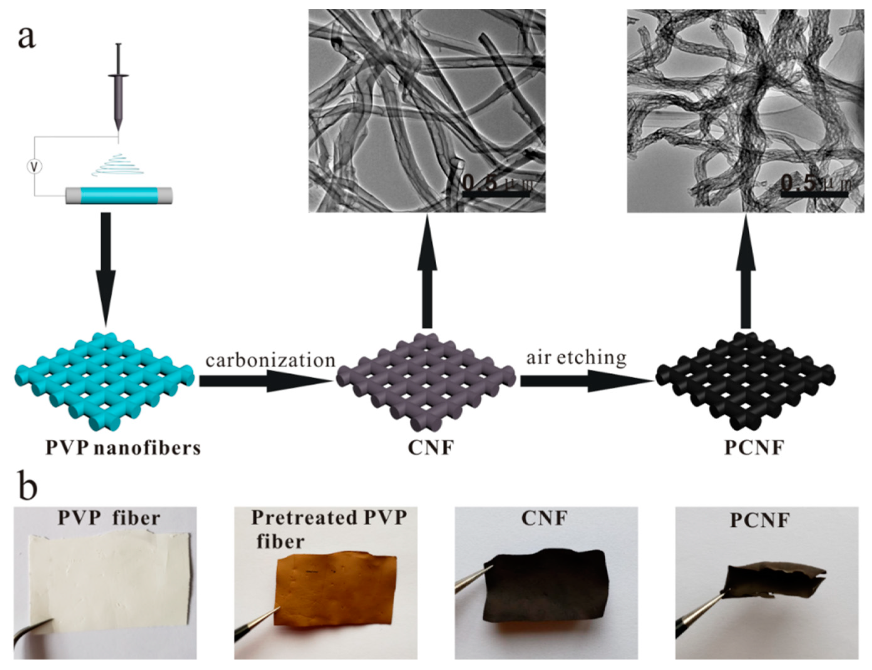
2.1. Preparation of PCNF

All the chemical agents were analytical reagent and obtained from Sinopharm Chemical Reagent Co. Ltd. The PCNF thin film were synthesized by a simple electrospinning process. Firstly, 2.34 g polyvinyl-pyrrolidone (PVP, Mw = 1,300,000) was dissolved in 20 mL mixture solution of alcohol and soft water (V/V = 1:1) to obtain crystal liquor. After violently stirring for 24 h at 30 °C, the viscous precursor solution was used to fill up a plastic injector with a 22 G stainless steel pinhead. The electrospinning was performed under a 21 kV positive voltage with a flux rate of 15 µL min−1. An aluminum foil was used as a collector and the distance between pinhead tip and the surface of aluminum foil was 20 cm.
The collected PVP polymer films were exsiccated at 60 °C using vacuum drying chamber for 12 h to eliminate remaining menstruum. For the preparation of carbon nanofibers films (CNF), the dried films were stabilized under 280 °C for 2 h with a heat-up speed of 5 °C min−1 under atmospheric environment and were carbonized under inset ambient at 600 °C for 2 h with a heat-up speed of 2 °C min−1. Finally, the as-prepared CNF were heated at 600 °C for 20 min under atmospheric condition to obtain PCNF.

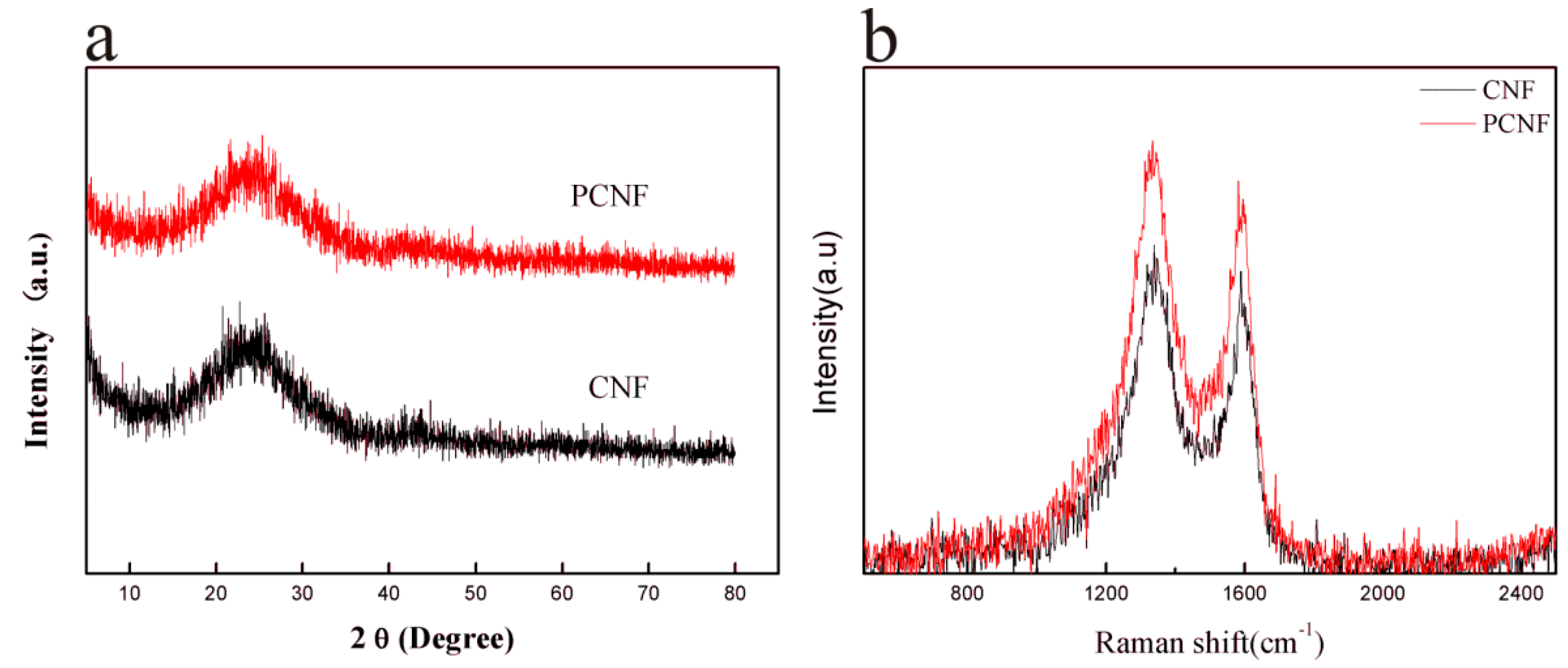
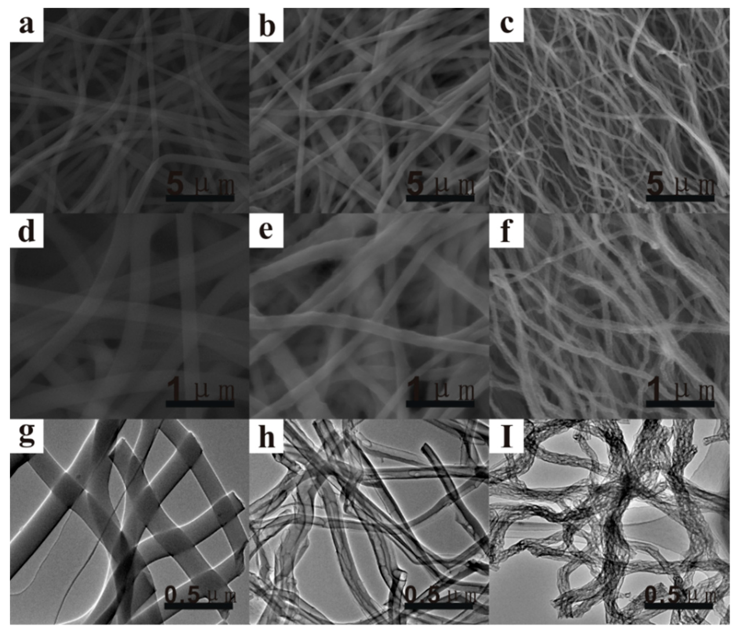
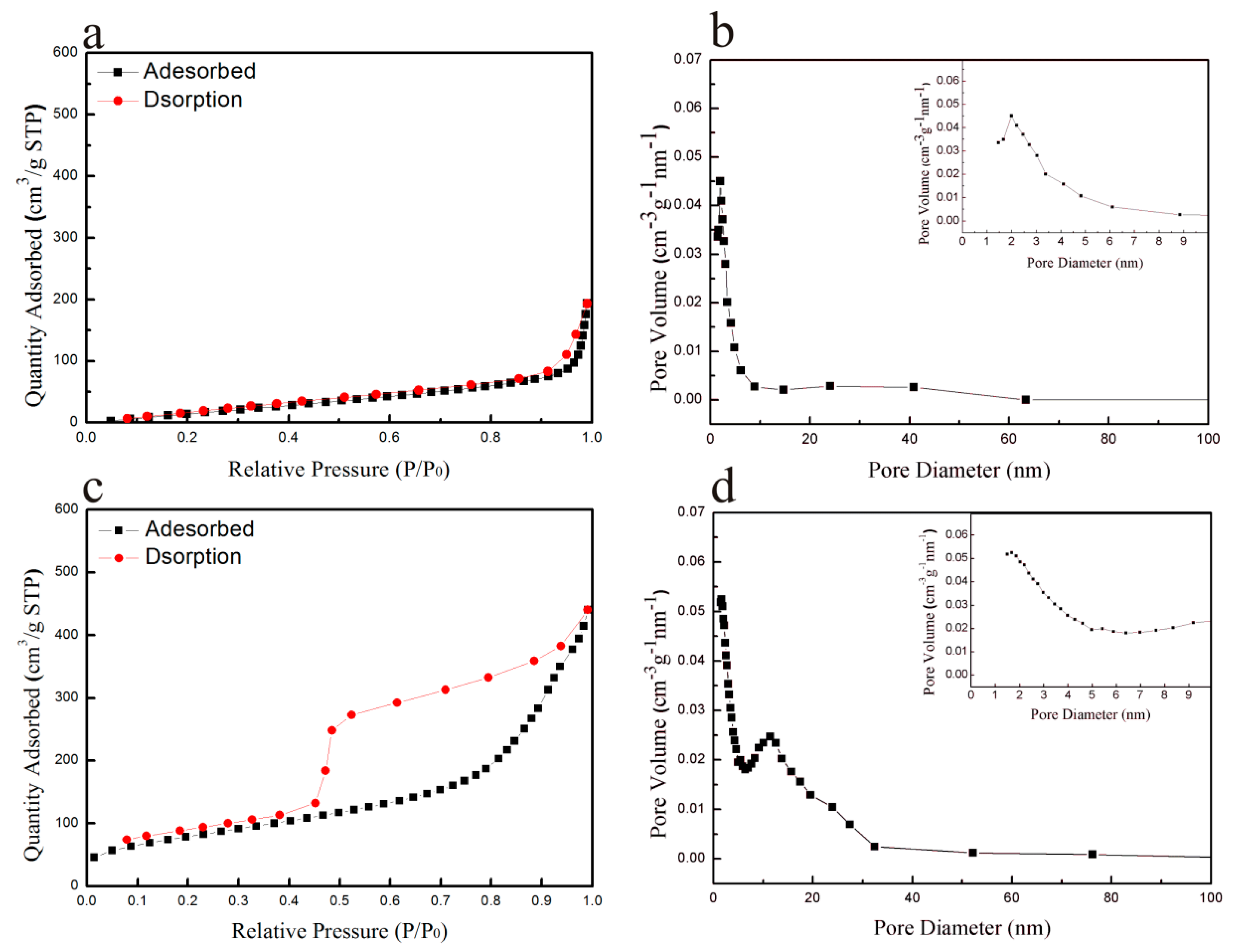
2.2. Material Characterizations

For characterizing crystalline structure of PCNF, X-ray diffraction (XRD, Bruker D8 Focus, BRUKER AXS, Karlsruhe, Germany) with Cu Ka radiation (λ = 0.15418 nm) was performed at a sweep speed of 5° min−1 in the 2θ range between 5° and 80°. Scanning electron microscopy (SEM, Philips-FEI, Tecnai Quanta 200F, FEI company, Hillsboro, America) and transmission electron microscopy (TEM, Tecnai G2 F20, FEI company, Hillsboro, America) were used to characterize the surface feature, the structure and distribution of the pores of fibers. In order to characterize the specific surface area and pore size of materials, BET measurements were performed on a 3H-2000PS1 Surface Area and Porosimetry Instrument.

2.3. Electrochemical Measurements

The electrochemical properties of the CNF and PCNF anode were evaluated by constructing a 2025-type coin cell without adding extra conductive agent and binder. The loading mass of anode was around 1 mg cm−1. The half-cells were constructed in Ar-filled glove box (MBRAUN, Germany). Lithium wafer and Celgard 2300 were employed as the counter electrode and diaphragm respectively. In addition, the mixture solution of 1 M LiPF6, ethylene carbonate (EC) and dimethyl carbonate (DMC) (V/V = 1:1) was used as a bath solution. To understand the performance of the assembled batteries, constant current charge-discharge measurements were carried on an NEWARE battery test system under various C-rates within a voltage range of 0.01–3.0 V. Meantime, electrochemical workstation (PARSTAT 2273, Princeton, NJ, USA) was used to perform electrochemical impedance spectroscopy (EIS) between 0.1 Hz to 100 KHz.

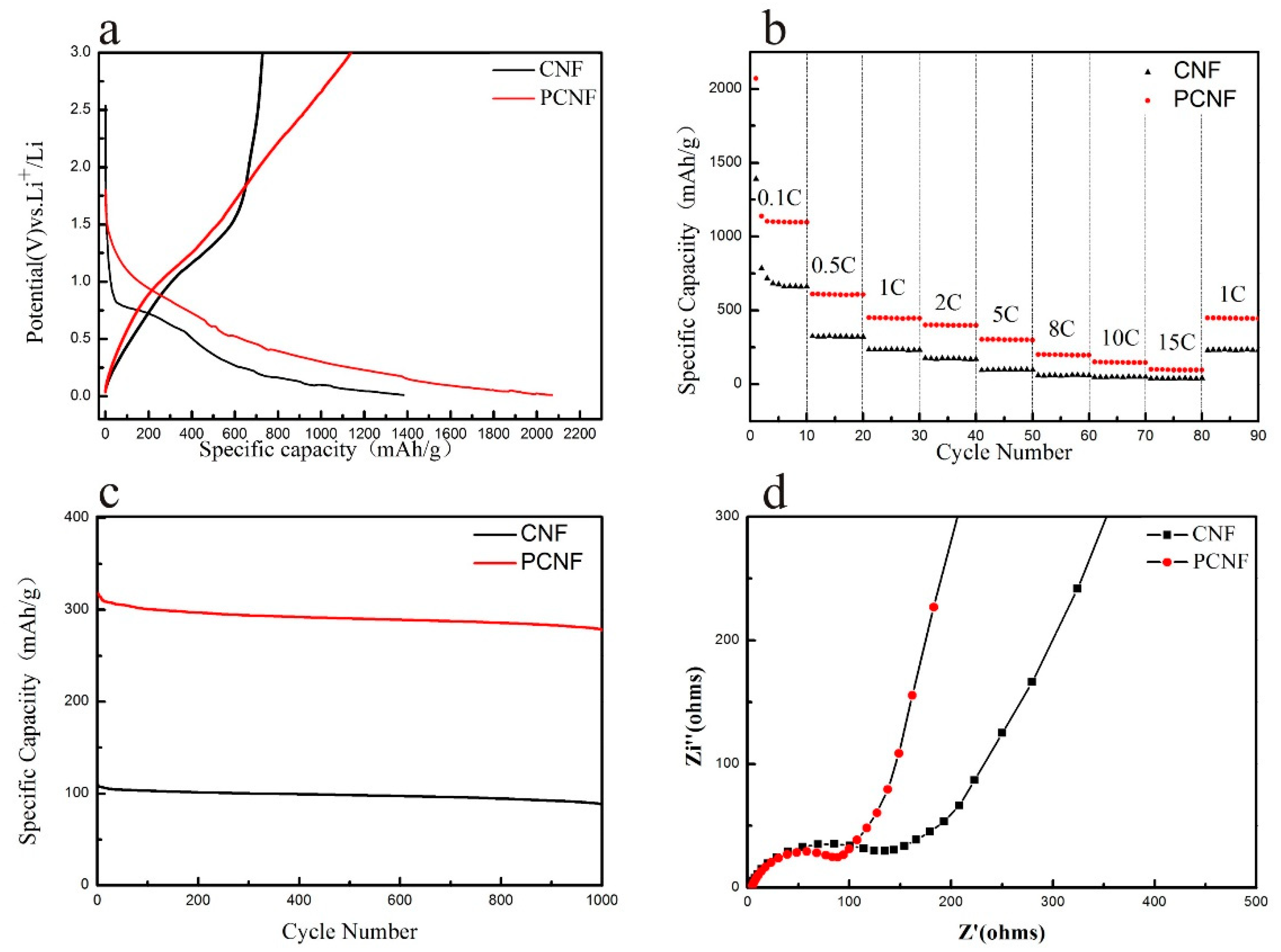
3. Results and Discussion

Figure 1 shows the synthetic process and photographic image of the PCNF samples. Firstly, a nanofibers thin film structure was prepared by a simple electrospinning technique following a stabilization process which made the thin film more stable due to cyclization and cross-linking reactions of PVP. Then the as-prepared PVP nanofibers films was heated under 600 °C for 2 h in argon atmosphere to produce CNF materials. At last, the PCNF sample was prepared by heating the CNF samples in air at 280 °C for 2 h. It is found that the obtained PCNF samples possess a great deal of mesopores which were irregularly scattered among every fiber and also exhibited good flexibility.
Figure 2a exhibits the XRD pattern of CNF (black) and PCNF (red) samples. It is found that almost the same diffraction pattern of CNF and PCNF samples has been obtained. In Figure 2a, the broad diffraction peaks and the inferior peak at 2θ of 25° and 43° which corresponded to the (002) graphitic layers and the (100) disordered carbon flat [42,43], respectively. It shows that the crystalline structure of PCNF sample didn’t make a difference during the air etching process, compared with that of CNF sample. In the Raman spectrum (Figure 2b), both of the CNF and PCNF sample had a couple of peaks at 1343 cm−1 and 1588 cm−1, which could be ascribed to D and G-band of a typical carbonaceous material.
In order to characterize the microstructure of the PVP nanofibers, CNF and PCNF samples, SEM and TEM tests were carried out. Figure 3 exhibited the SEM and TEM micrographs of PVP nanofibers (a, d, g), CNF nanofibers (b, e, h) and PCNF nanofibers (e, f, i). It is found from the images that similar interconnected nanofibers were interwoven into these thin film samples. The original PVP nanofiber thin film (Figure 3a,c) was glossy on the outside and the diameter of each of the nanofibers was about 300–400 nm. So to improve the electrical property of PVP nanofibers, the samples were carbonized under Ar atmosphere. The obtained CNF thin film still maintained the original PVP nanofiber structure, but the diameter decreased to 200–300 nm and the surface became rough (Figure 3b,e). The constriction which gave rise to PVP nanofibers was mainly brought about by the evaporation of solvent and the decomposition of PVP under a high temperature. After undergoing the air etching process, the PCNF still kept a uniform cylindrical fiber structure. However, the diameter and appearance changed obviously, the carbon nanofibers occurred severely to the sink mark and the surface became more porous and rough due to the carbon reacting with oxygen (Figure 3c,f). TEM test were performed to further confirm the porosity characteristic of PCNF samples. As Figure 3g–i showed that the carbon nanofibers shrunk from 300–400 nm to 100–150 nm and the surface became obviously porous after a carbonization and an air etching process.
To acquire specific information of the specific surface area and hole sizes for CNF and PCNF samples, nitrogen adsorption-desorption tests were carried out. Figure 4 exhibits shows the N2 adsorption-desorption isotherms and hole sizes distribution of CNF and PCNF samples. Compared with the CNF samples (Figure 4a), PCNF nanofibers showed a type-IV isotherm with H3-type hysteresis loop and demonstrated a high specific surface area of 288.50 m2 g−1 (Figure 4c) which was twice that of the CNF (117.84 m2 g−1, Figure 4a), implying a more porous structure which could provide more active sites for lithium storage. This is attributed to oxygen reacting with carbon nanofibers during the air etching process. These results were in good conformity to the SEM and TEM measurements. In the bore diameters distribution graphs shown in Figure 4b,d, the CNF sample had a main peak at 2 nm and the adsorption capacity was mainly derived from micropores. However, plenty of mesopores in the range of 2–100 nm were observed in the PCNF sample. For electrode, the mesopore structure in the PCNF sample could be more suitable for rapid charge and discharge, due to a greater wettability and accessibility of electrolyte, quicken lithium ion diffusion and transport from the bath solution to the surface of the electrode, in comparison with the micropore feature. Therefore, the presence of a large proportion of mesopore in PCNF could be expected to lead to an improved electrochemical performance in LiBs.
To assess the electrochemical properties, the CNF and PCNF samples were used as anodes without adding any binder or conductive additive for button cell. In the coin cells, metallic lithium and Celgard 2300 film were employed as the counter electrode and separator, respectively. Figure 5a displays the first charge-discharge images of the CNF and PCNF materials at 0.1 C at a working potential from 0.01 to 3.0 V (vs. Li/Li+). For the maiden charge and discharge cycle, the PCNF showed a high discharge capacity of 2070 mAh g−1, which was much better than the CNF (1391 mAh g−1). Nevertheless, the invertible discharge capacities decreased to 1138 and 785 mAh g−1. In the initial charge-discharge curve, both of CNF and PCNF sample had an obvious irreversible capacity loss, their initial coulombic efficiency was only around 55% and 56%. This large irreversible capacity loss was an inherent defect for almost all carbon electrodes, mainly due to the blemished structure of samples that showed irreversibly depleted extra lithium ions [43,44] and the appearance of solid-state electrolyte interphase (SEI) film [43,44,45,46,47]. It also irreversibly consumed an abundance of electrolyte and lithium ions. Interestingly, comparing with graphite materials [26,48], the PCNF sample shows a much higher invertible capacity up to 1138 mAh g−1, which will be helpful to obtain high energy anode materials of LIBs.
Good rate performance had a significant impact on the application of LIBs in the energy storage field. The rate capabilities of the CNF and PCNF anode materials were further evaluated under different C-rates and the results were seen in Figure 5b. The cells with CNF anode displayed invertible specific capacities of 785, 322.8, 234.5, 170.7, 98.9, 60, 48.7, 39.1 mAh g−1 at 0.1 C, 0.5 C, 1 C, 2 C, 5 C, 8 C, 10 C and 15 C, respectively. Meantime, the homologous specific discharge capacities of the PCNF sample were 1138, 609.8, 450.4, 401.9, 303.8, 201.3, 151 and 101.2 mAh g−1, far more than that of the CNF anode. Furthermore, after cycling for 80 times at different C-rates, the discharge capacity recovered to 449.4 mAh g−1 while the ampere density was returned to 1 C, following a high capacity retention of 99%, implying the positive performance rates of the PCNF sample. In addition, the long circulation measurements were conducted under a high C-rate of 5 C of the CNF and PCNF electrode were displayed in Figure 5c. It could be obviously observed that the PCNF anode showed a good invertible capacity of 317.7 mAh g−1 at initial discharge process and remained at 278 mAh g−1 for the 1000th circulation, with a high capacity retention of 87.51% and a capacity decrease ratio as low as ~0.013% for each time. In contrast, the CNF sample exhibited a relative poor discharge specific capacity of 109.7 mAh g−1 at the initial discharge process and 88.3 mAh g−1 after cycling for 1000 times, respectively. Based on these results, the PCNF electrode sample with hierarchical pore thin film structures delivers a remarkable rate capability as well as cycling ability which was better than the carbon materials reported in previous work (Table 1). The porous network structure derived from PVP precursor could speed up the conveying of both electron and lithium ion in order to enhance the electrochemical property and serve as a feasible electrode for LIBs.
Finally, electrochemical impedance spectroscopic (EIS) experiments were employed to further understand the kinetics of the CNF and PCNF samples. As shown in Figure 5d, the EIS Nyquist plots consisted of a depressed semicircle located on the high-frequency region and an oblique line seated at the low-frequency region for both of the CNF and PCNF electrodes, which accorded with the electrode/electrolyte interphase interfacial charge-transfer resistance (Rct) [49,50] and the Warburg impedance (Wp). Obviously, the PCNF electrode (90 Ω) showed a much lower value of Rct than that of the CNF (135 Ω) because of its large BET and multi-level porous framework which could facilitated transportation of both electron and ion, bringing about an excellent rate performance and outstanding cycling ability.

4. Conclusions

In summary, a highly porous nanofibers film has been fabricated via simple and low-cost electrospinning method followed by a carbonization and air etching process. As expected, the obtained nanofiber thin film exhibits an interconnected porous network and a highly porous surface which significantly increased lithium ion storage sites. It is found that the PCNF anode shows a high invertible capacity of 1138 mAh g−1 at 0.1 C. Furthermore, a low capacity decrease ratio of ~0.013% for each time upon 1000 cycles at 5C and a good discharge capacity of 101.2 mAh g−1 even at when a high C-rate of 15 C is obtained, shows a favorable cycling property and a good rate performance. The significant enhancement on electrochemical properties can be ascribed to two main factors: (1) the interconnected carbon nanofibers network of the PCNF electrode remarkably improved the conductivity of materials; (2) the hierarchical porous architecture not only provided enough space for storage of more Li+, but also promoted the carriage transportation of ions and electrons. More interestingly, this work delivers a portable and cheap method to prepare high-perform anode material for lithium ion batteries.

Author Contributions

Conceptualization, J.C.; Data curation, S.F.; Formal analysis, W.L.; Funding acquisition, J.C.; Methodology, J.Y.; Resources, Z.Y.; Writing—original draft, P.Z.; Writing—review & editing, J.C.

Funding

This research was funded by the National Natural Science Foundation of China (No. 21263016, 21363015, 51662029).

Conflicts of Interest

The authors declare no conflict of interest.

References

  1. Lu, X.; Wang, C.; Wei, Y. One-dimensional composite nanomaterials: Synthesis by electrospinning and their applications. Small 2009, 5, 2349–2370. [Google Scholar] [CrossRef]
  2. Goodenough, J.B.; Kim, Y. Challenges for rechargeable Li batteries. Chem. Mater. 2009, 22, 587–603. [Google Scholar] [CrossRef]
  3. Zhang, L.; Wu, H.B.; Lou, X.W. Iron-oxide-based advanced anode materials for lithium-ion batteries. Adv. Energy Mater. 2014, 4, 1300958. [Google Scholar] [CrossRef]
  4. Scrosati, B.; Hassoun, J.; Sun, Y.K. Lithium-ion batteries. A look into the future. Energy Environ. Sci. 2011, 4, 3287–3295. [Google Scholar] [CrossRef]
  5. Whittingham, M.S. Lithium batteries and cathode materials. Chem. Rev. 2004, 104, 4271–4302. [Google Scholar] [CrossRef]
  6. Ohsaki, T.; Kanda, M.; Aoki, Y.; Shiroki, H.; Suzuki, S. High-capacity lithium-ion cells using graphitized mesophase-pitch-based carbon fiber anodes. J. Power Sources 1997, 68, 102–105. [Google Scholar] [CrossRef]
  7. Leroux, F.; Metenier, K.; Gautier, S.; Frackowiak, E.; Bonnamy, S.; Beguin, F. Electrochemical insertion of lithium in catalytic multi-walled carbon nanotubes. J. Power Sources 1999, 81, 317–322. [Google Scholar] [CrossRef]
  8. Gao, B.; Bower, C.; Lorentzen, J.D.; Fleming, L.; Kleinhammes, A.; Tang, X.P.; McNeil, L.E.; Wu, Y.; Zhou, O. Enhanced saturation lithium composition in ball-milled single-walled carbon nanotubes. Chem. Phys. Lett. 2000, 327, 69–75. [Google Scholar] [CrossRef]
  9. Landi, B.J.; Ganter, M.J.; Cress, C.D.; DiLeo, R.A.; Raffaelle, R.P. Carbon nanotubes for lithium ion batteries. Energy Environ. Sci. 2009, 2, 638–654. [Google Scholar] [CrossRef]
  10. Kim, C.; Yang, K.S. Electrochemical properties of carbon nanofiber web as an electrode for supercapacitor prepared by electrospinning. Appl. Phys. Lett. 2003, 83, 1216–1218. [Google Scholar] [CrossRef]
  11. Yoon, S.H.; Park, C.W.; Yang, H.; Korai, Y.; Mochida, I.; Baker, R.T.K.; Rodriguez, N.M. Novel carbon nanofibers of high graphitization as anodic materials for lithium ion secondary batteries. Carbon 2004, 42, 21–32. [Google Scholar] [CrossRef]
  12. Tarascon, J.M.; Armand, M. Issues and challenges facing rechargeable lithium batteries. In Materials for Sustainable Energy: A Collection of Peer-Reviewed Research and Review Articles from Nature Publishing Group; Nature Publishing Group: London, UK, 2011; pp. 171–179. [Google Scholar]
  13. Kaskhedikar, N.A.; Maier, J. Lithium storage in carbon nanostructures. Adv. Mater. 2009, 21, 2664–2680. [Google Scholar] [CrossRef]
  14. Candelaria, S.L.; Shao, Y.; Zhou, W.; Li, X.; Xiao, J.; Zhang, J.G.; Wang, Y.; Liu, J.; Li, J.H.; Cao, G.Z. Nanostructured carbon for energy storage and conversion. Nano Energy 2012, 1, 195–220. [Google Scholar] [CrossRef]
  15. Liu, Y.; Wang, X.; Song, X.; Dong, Y.; Yang, L.; Wang, L.; Jia, D.; Zhao, Z.; Qiu, J. Interlayer expanded MoS2 enabled by edge effect of graphene nanoribbons for high performance lithium and sodium ion batteries. Carbon 2016, 109, 461–471. [Google Scholar] [CrossRef]
  16. Luo, Y.; Luo, N.; Kong, W.; Wu, H.; Wang, K.; Fan, S.; Duan, W.; Wang, J. Multifunctional Interlayer Based on Molybdenum Diphosphide Catalyst and Carbon Nanotube Film for Lithium-Sulfur Batteries. Small 2018, 14, 1702853. [Google Scholar] [CrossRef]
  17. Zhu, C.; Fu, S.; Song, J.; Shi, Q.; Su, D.; Engelhard, M.H.; Li, X.; Xiao, D.; Li, D.; Estevez, L.; et al. Self-Assembled Fe-N-Doped Carbon Nanotube Aerogels with Single-Atom Catalyst Feature as High-Efficiency Oxygen Reduction Electrocatalysts. Small 2017, 13, 1603407. [Google Scholar] [CrossRef]
  18. Niazi, N.K.; Bibi, I.; Shahid, M.; Ok, Y.S.; Burton, E.D.; Wang, H.; Shaheen, S.M.; Rinklebe, J.; Lüttgeb, A. Arsenic removal by perilla leaf biochar in aqueous solutions and groundwater: An integrated spectroscopic and microscopic examination. Environ. Pollut. 2018, 232, 31–41. [Google Scholar] [CrossRef]
  19. Wang, Q.; Li, H.; Chen, L.; Huang, X. Monodispersed hard carbon spherules with uniform nanopores. Carbon 2001, 39, 2211–2214. [Google Scholar] [CrossRef]
  20. Li, H.; Wang, Z.; Chen, L.; Huang, X. Research on advanced materials for Li-ion batteries. Adv. Mater. 2009, 21, 4593–4607. [Google Scholar] [CrossRef]
  21. Wang, X.X.; Wang, J.N.; Chang, H.; Zhang, Y.F. Preparation of short carbon nanotubes and application as an electrode material in Li-ion batteries. Adv. Funct. Mater. 2007, 17, 3613–3618. [Google Scholar] [CrossRef]
  22. Yang, Z.; Sang, S.; Huang, K.; Wu, H.Q. Lithium insertion into the raw multi-walled carbon nanotubes pre-doped with lithium-An electrochemical impedance study. Diam. Relat. Mater. 2004, 13, 99–105. [Google Scholar] [CrossRef]
  23. Yang, Z.; Wu, H. Electrochemical intercalation of lithium into carbon nanotubes. Solid State Ion. 2001, 143, 173–180. [Google Scholar] [CrossRef]
  24. Cui, G.; Gu, L.; Kaskhedikar, N.; van Aken, P.A.; Maier, J. A novel germanium/carbon nanotubes nanocomposite for lithium storage material. Electrochim. Acta 2010, 55, 985–988. [Google Scholar] [CrossRef]
  25. Wu, Y.; Reddy, M.V.; Chowdari, B.V.R.; Ramakrishna, S. Long-term cycling studies on electrospun carbon nanofibers as anode material for lithium ion batteries. ACS Appl. Mater. Interfaces 2013, 5, 12175–12184. [Google Scholar] [CrossRef]
  26. Kim, C.; Yang, K.S.; Kojima, M.; Yoshida, K.; Kim, Y.J.; Kim, Y.A.; Endo, M. Fabrication of electrospinning-derived carbon nanofiber webs for the anode material of lithium-ion secondary batteries. Adv. Funct. Mater. 2006, 16, 2393–2397. [Google Scholar] [CrossRef]
  27. Tung, V.C.; Chen, L.M.; Allen, M.J.; Wassei, J.K.; Nelson, K.; Kaner, R.B.; Yang, Y. Low-temperature solution processing of graphene-carbon nanotube hybrid materials for high-performance transparent conductors. Nano Lett. 2009, 9, 1949–1955. [Google Scholar] [CrossRef] [PubMed]
  28. Cui, G.; Gu, L.; Zhi, L.; Kaskhedikar, N.V.; van Aken, P.A.; Müllen, K.; Maier, J. A germanium-carbon nanocomposite material for lithium batteries. Adv. Mater. 2008, 20, 3079–3083. [Google Scholar] [CrossRef]
  29. Endo, M.; Hayashi, T.; Kim, Y.A.; Terrones, M.; Dresselhaus, M.S. Applications of carbon nanotubes in the twenty-first century. Philos. Trans. R. Soc. Lond. A Math. Phys. Eng. Sci. 2004, 362, 2223–2238. [Google Scholar] [CrossRef]
  30. Girishkumar, G.; McCloskey, B.; Luntz, A.C.; Swanson, S.; Wilcke, W. Lithium-air battery: Promise and challenges. J. Phys. Chem. Lett. 2010, 1, 2193–2203. [Google Scholar] [CrossRef]
  31. Pan, D.; Wang, S.; Zhao, B.; Wu, M.; Zhang, H.; Wang, Y.; Jiao, Z. Li storage properties of disordered graphene nanosheets. Chem. Mater. 2009, 21, 3136–3142. [Google Scholar] [CrossRef]
  32. Kang, C.; Lahiri, I.; Baskaran, R.; Kim, W.G.; Sun, Y.K.; Choi, W. 3-dimensional carbon nanotube for Li-ion battery anode. J. Power Sources 2012, 219, 364–370. [Google Scholar] [CrossRef]
  33. Xiao, Q.; Fan, Y.; Wang, X.; Susantyoko, R.A.; Zhang, Q. A multilayer Si/CNT coaxial nanofiber LIB anode with a high areal capacity. Energy Environ. Sci. 2014, 7, 655–661. [Google Scholar] [CrossRef]
  34. Dong, Y.; Yu, M.; Wang, Z.; Liu, Y.; Wang, X.; Zhao, Z.; Qiu, J. A Top-Down Strategy toward 3D Carbon Nanosheet Frameworks Decorated with Hollow Nanostructures for Superior Lithium Storage. Adv. Funct. Mater. 2016, 26, 7590–7598. [Google Scholar] [CrossRef]
  35. Xu, W.; Wang, J.; Ding, F.; Chen, X.; Nasybulin, E.; Zhang, Y.; Zhang, J.G. Lithium metal anodes for rechargeable batteries. Energy Environ. Sci. 2014, 7, 513–537. [Google Scholar] [CrossRef]
  36. Milczarek, G.; Ciszewski, A.; Stepniak, I. Oxygen-doped activated carbon fiber cloth as electrode material for electrochemical capacitor. J. Power Sources 2011, 196, 7882–7885. [Google Scholar] [CrossRef]
  37. Long, W.; Fang, B.; Ignaszak, A.; Wu, Z.; Wang, Y.J.; Wilkinson, D. Biomass-derived nanostructured carbons and their composites as anode materials for lithium ion batteries. Chem. Soc. Rev. 2017, 46, 7176–7190. [Google Scholar] [CrossRef]
  38. Ou, J.; Yang, L.; Xi, X. Biomass inspired nitrogen doped porous carbon anode with high performance for lithium ion batteries. Chin. J. Chem. 2016, 34, 727–732. [Google Scholar] [CrossRef]
  39. Xu, G.; Han, J.; Ding, B.; Nie, P.; Pan, J.; Dou, H.; Li, H.; Zhang, X. Biomass-derived porous carbon materials with sulfur and nitrogen dual-doping for energy storage. Green Chem. 2015, 17, 1668–1674. [Google Scholar] [CrossRef]
  40. Li, Z.; Xu, Z.; Tan, X.; Wang, H.; Holt, C.M.; Stephenson, T.; Olsen, B.; Mitlin, D. Mesoporous nitrogen-rich carbons derived from protein for ultra-high capacity battery anodes and supercapacitors. Energy Environ. Sci. 2013, 6, 871–878. [Google Scholar] [CrossRef]
  41. Qie, L.; Chen, W.M.; Wang, Z.H.; Shao, Q.G.; Li, X.; Yuan, L.X.; Hu, X.L.; Zhang, W.X.; Huang, Y.H. Nitrogen-doped porous carbon nanofiber webs as anodes for lithium ion batteries with a superhigh capacity and rate capability. Adv. Mater. 2012, 24, 2047–2050. [Google Scholar] [CrossRef]
  42. Lee, G.J.; Pyun, S.I. Effect of microcrystallite structures on electrochemical characteristics of mesoporous carbon electrodes for electric double-layer capacitors. Electrochim. Acta 2006, 51, 3029–3038. [Google Scholar] [CrossRef]
  43. Cai, J.; Li, W.; Zhao, P.; Yu, J.; Yang, Z. Low-Cost and High-Performance Electrospun Carbon Nanofiber Film Anodes. Int. J. Electrochem. Sci. 2018, 13, 2934–2944. [Google Scholar] [CrossRef]
  44. Kim, J.S.; Park, Y.T. Characteristics of surface films formed at a mesocarbon microbead electrode in a Li-ion battery. J. Power Sources 2000, 91, 172–176. [Google Scholar] [CrossRef]
  45. Arora, P.; White, R.E.; Doyle, M. Capacity fade mechanisms and side reactions in lithium-ion batteries. J. Electrochem. Soc. 1998, 145, 3647–3667. [Google Scholar] [CrossRef]
  46. Wang, C.; Appleby, A.J.; Little, F.E. Irreversible capacities of graphite anode for lithium-ion batteries. J. Electroanal. Chem. 2002, 519, 9–17. [Google Scholar] [CrossRef]
  47. Kim, C.; Jeong, Y.I.; Ngoc, B.T.N.; Yang, K.S.; Kojima, M.; Kim, Y.A.; Endo, M.; Lee, W.J. Synthesis and characterization of porous carbon nanofibers with hollow cores through the thermal treatment of electrospun copolymeric nanofiber webs. Small 2007, 3, 91–95. [Google Scholar] [CrossRef]
  48. Ji, L.; Zhang, X. Fabrication of porous carbon nanofibers and their application as anode materials for rechargeable lithium-ion batteries. Nanotechnology 2009, 20, 155705. [Google Scholar] [CrossRef]
  49. Xu, K.; Zhang, S.; Jow, R. Electrochemical impedance study of graphite/electrolyte interface formed in LiBOB/PC electrolyte. J. Power Sources 2005, 143, 197–202. [Google Scholar] [CrossRef]
  50. Zhang, Y.; Wang, C.Y.; Tang, X. Cycling degradation of an automotive LiFePO4 lithium-ion battery. J. Power Sources 2011, 196, 1513–1520. [Google Scholar] [CrossRef]
  51. Ji, L.; Lin, Z.; Medford, A.J.; Zhang, X. Porous carbon nanofibers from electrospun polyacrylonitrile/SiO2 composites as an energy storage material. Carbon 2009, 47, 3346–3354. [Google Scholar] [CrossRef]
  52. Ji, L.; Yao, Y.; Toprakci, O.; Lin, Z.; Liang, Y.; Shi, Q.; Medford, A.; Millns, C.; Zhang, X. Fabrication of carbon nanofiber-driven electrodes from electrospun polyacrylonitrile/polypyrrole bicomponents for high-performance rechargeable lithium-ion batteries. J. Power Sources 2010, 195, 2050–2056. [Google Scholar] [CrossRef]
  53. Kumar, P.S.; Sahay, R.; Aravindan, V.; Sundaramurthy, J.; Ling, W.C.; Thavasi, V.; Mhaisalkar, S.G.; Madhavi, S.; Ramakrishna, S. Free-standing electrospun carbon nanofibres-a high performance anode material for lithium-ion batteries. J. Phys. D Appl. Phys. 2012, 45, 265302. [Google Scholar] [CrossRef]
  54. Peng, Y.T.; Lo, C.T. Electrospun porous carbon nanofibers as lithium ion battery anodes. J. Solid State Electrochem. 2015, 19, 3401–3410. [Google Scholar] [CrossRef]
  55. Dong, L.; Wang, G.; Li, X.; Xiong, D.; Yan, B.; Chen, B.; Li, D.; Cui, Y. PVP-derived carbon nanofibers harvesting enhanced anode performance for lithium ion batteries. RSC Adv. 2016, 6, 4193–4199. [Google Scholar] [CrossRef]
  56. Stojanovska, E.; Pampal, E.S.; Kilic, A.; Quddus, M.; Candan, Z. Developing and characterization of lignin-based fibrous nanocarbon electrodes for energy storage devices. Compos. Part B Eng. 2019, 158, 239–248. [Google Scholar] [CrossRef]
Figure 1. (a) Diagrammatization of synthesis process of the polyporous carbon nanofibers films; (b) Photographic images of the PVP fiber, pretreated PVP fiber, CNF and PCNF.
Applsci 09 01016 g001
Figure 2. The XRD and Raman images of CNF (black) and PCNF (red) samples: (a) XRD pattern; (b) Raman pattern.
Applsci 09 01016 g002
Figure 3. SEM and TEM measurements (images) of PVP, CNF and PCNF nanofibers: (a,d,g) PVP nanofibers; (b,e,h) CNF nanofibers; (c,f,i) PCNF nanofibers.
Applsci 09 01016 g003
Figure 4. (a) N2 adsorption-desorption isotherms of the CNF; (b) pore diameter distribution of the CNF; (c) N2 adsorption-desorption isotherms of the PCNF; (d) pore diameter distributions of the PCNF.
Applsci 09 01016 g004
Figure 5. Electrochemical measurements of CNF and PCNF samples. (a) First discharge-charge images at 0.1 C; (b) rate capability; (c) Long cycling capability at 5 C; (d) electrochemical impedance spectra.
Applsci 09 01016 g005
Table 1. The comparison of electrochemical performance of various carbon materials.
MaterialsInitial Discharge CapacityRate PerformanceCycling PerformanceRef.
Short Carbon Nanotubes1291 mAh g−1 at 25 mA g−1-410 mAh g−1 at 25 mA g−1 after 50 cycles[21]
Porous carbon nanofibers1900 mAh g−1 at 50 mA g−1-- [51]
Carbon nanofiber885 mAh g−1 at 50 mA g−1345 mAh g−1 at 0.54 C454 mAh g−1 at 0.13 C after 80 cycles [52]
Free-standing carbon nanofibers 826 mAh g−1 at 200 mA g−1125 mAh g−1 at 900 mA g−1 143 mAh g−1 at 200 mA g−1 after 200 cycles [53]
Porous carbon nanofibers950 mAh g−1 at 150 mA g−1256 mAh g−1 at 900 mA g−1 354 mAh g−1 at 200 mA g−1 after 100 cycles[54]
PVP-derived carbon nanofibers1770 mAh g−1 at 100 mA g−1650 mAh g−1 at 250 mA g−1766 mAh g−1 at 100 mA g−1 after 100 cycles[55]
Nitrogen Doped Porous Carbon880 mAh g−1 at 0.1 C190 mAh g−1 at 10 C410 mAh g−1 at 5 C after 500 cycles[38]
Lignin-based fibrous nanocarbon1471 mAh g−1 at 50 mA g−175 mAh g−1 at 1000 mA g−1110 mAh g−1 at 300 mA g−1 after 1000 cycles[56]
Porous Carbon Nanofibers Film2070 mAh g−1 at 0.1 C101 mAh g−1 at 15 C278 mAh g−1 at 5 C after 1000 cyclesThis work

