Aerodynamic and Structural Characteristics of a Centrifugal Compressor Impeller


Abstract
:1. Introduction
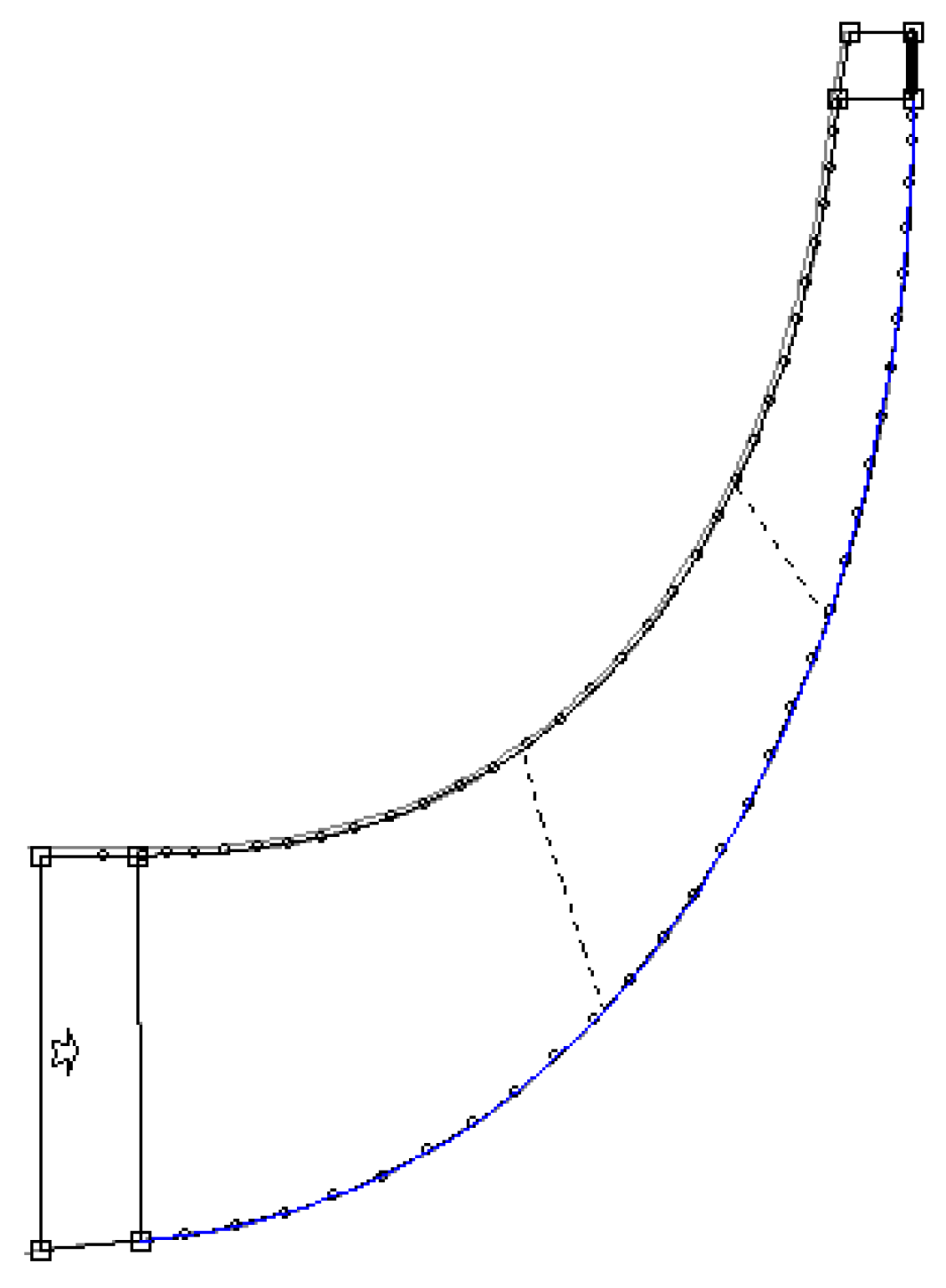
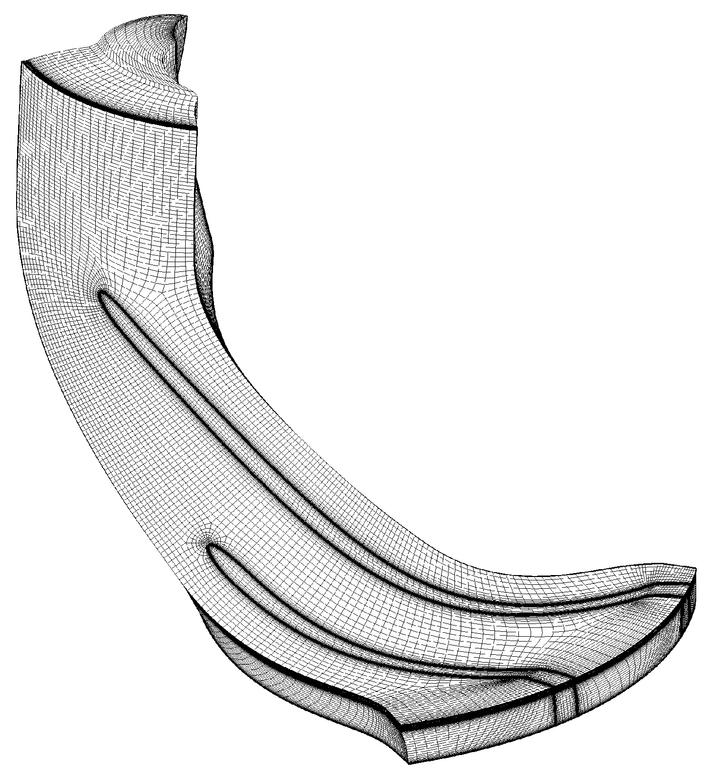
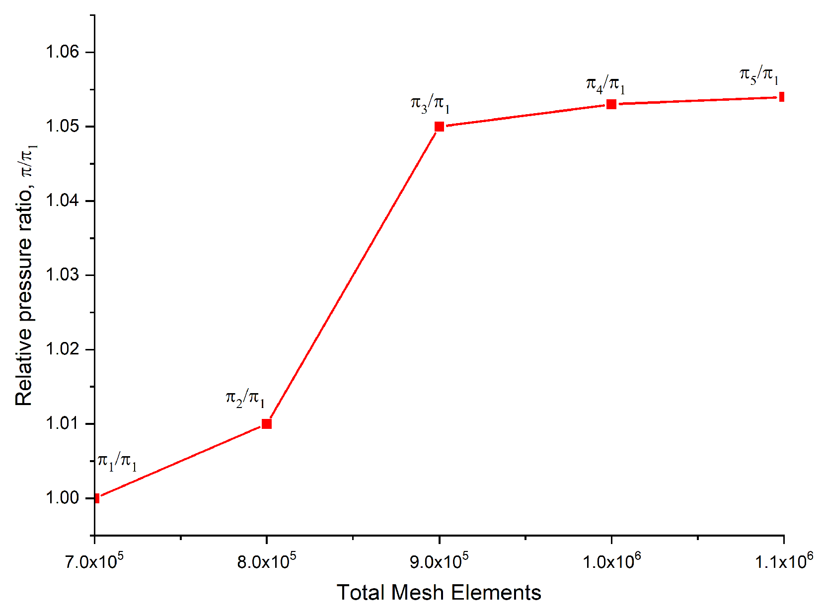
2. Methodology
3. Results and Discussion
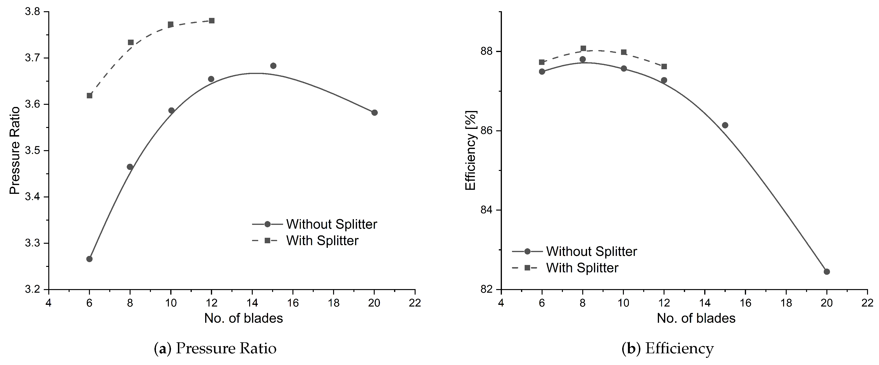
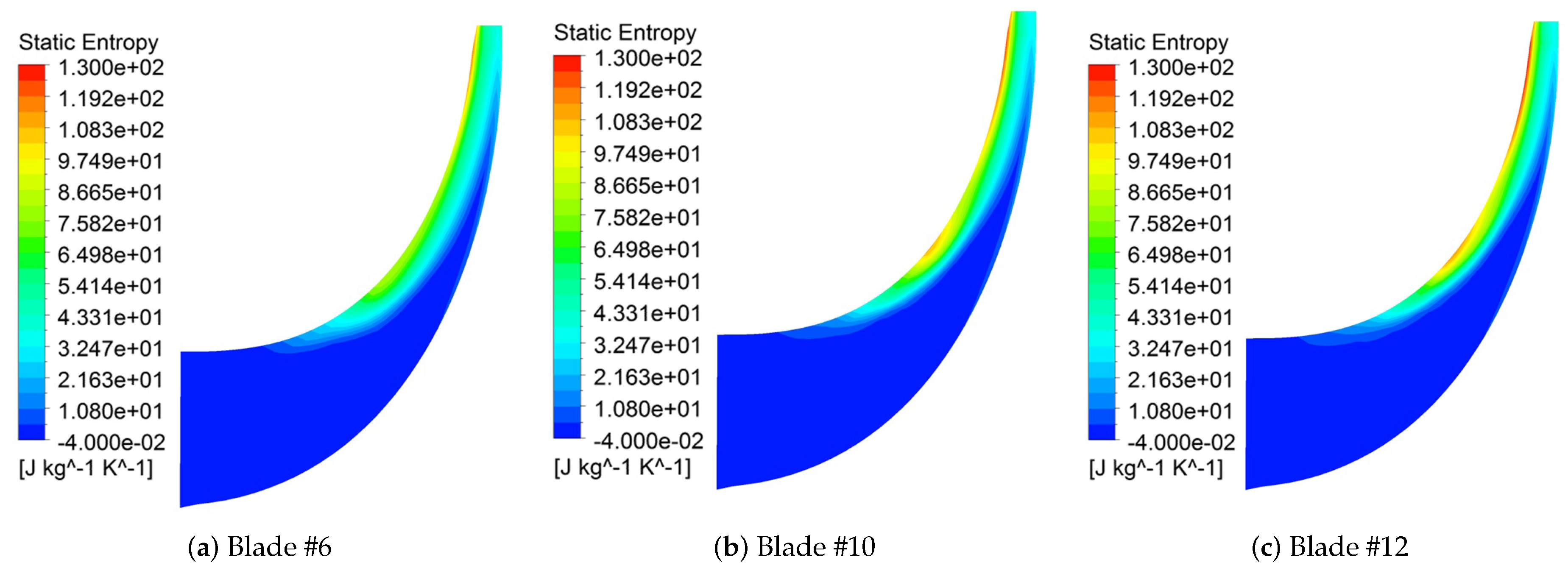
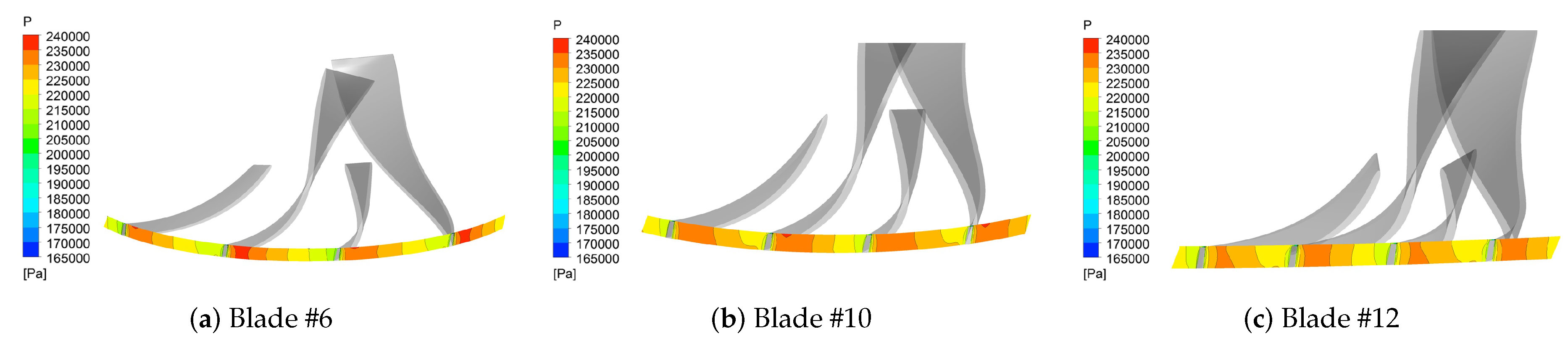
3.1. Aerodynamic Performance
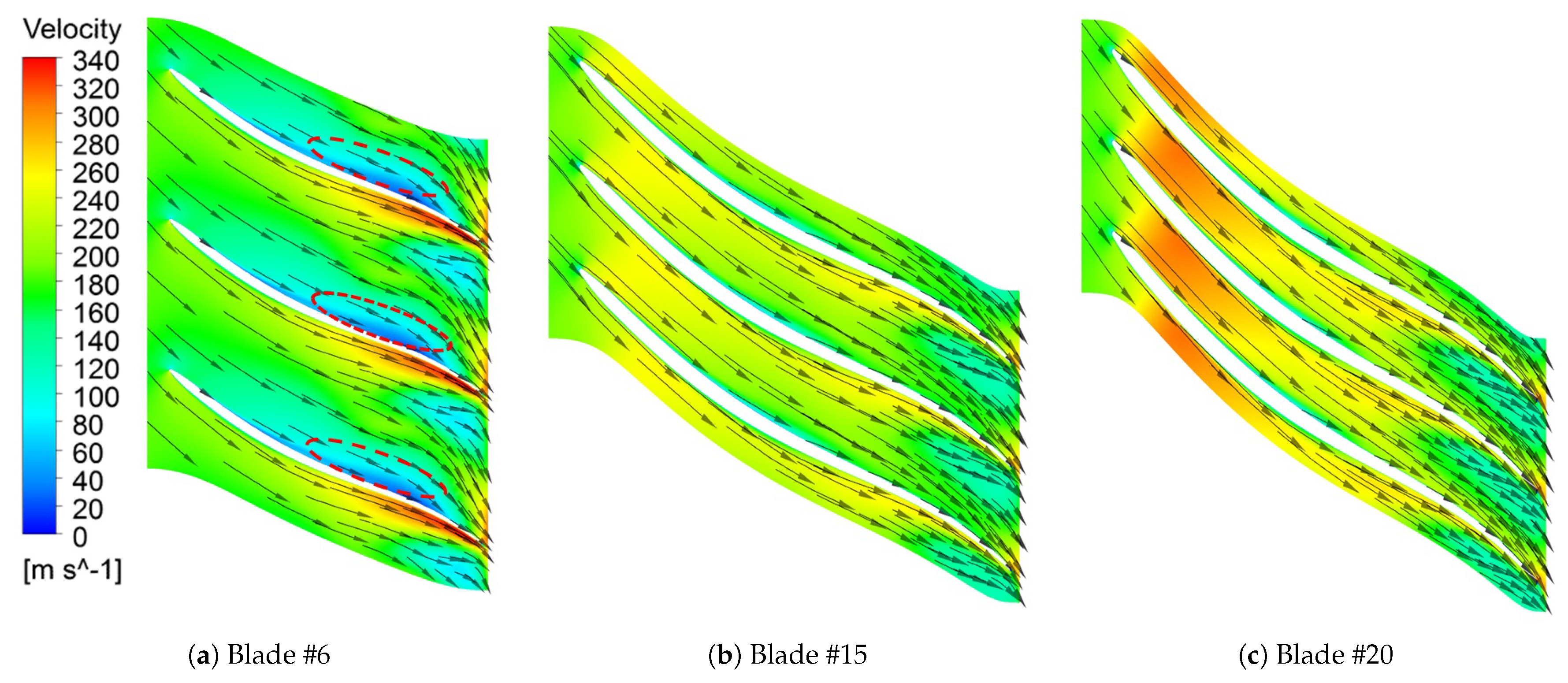
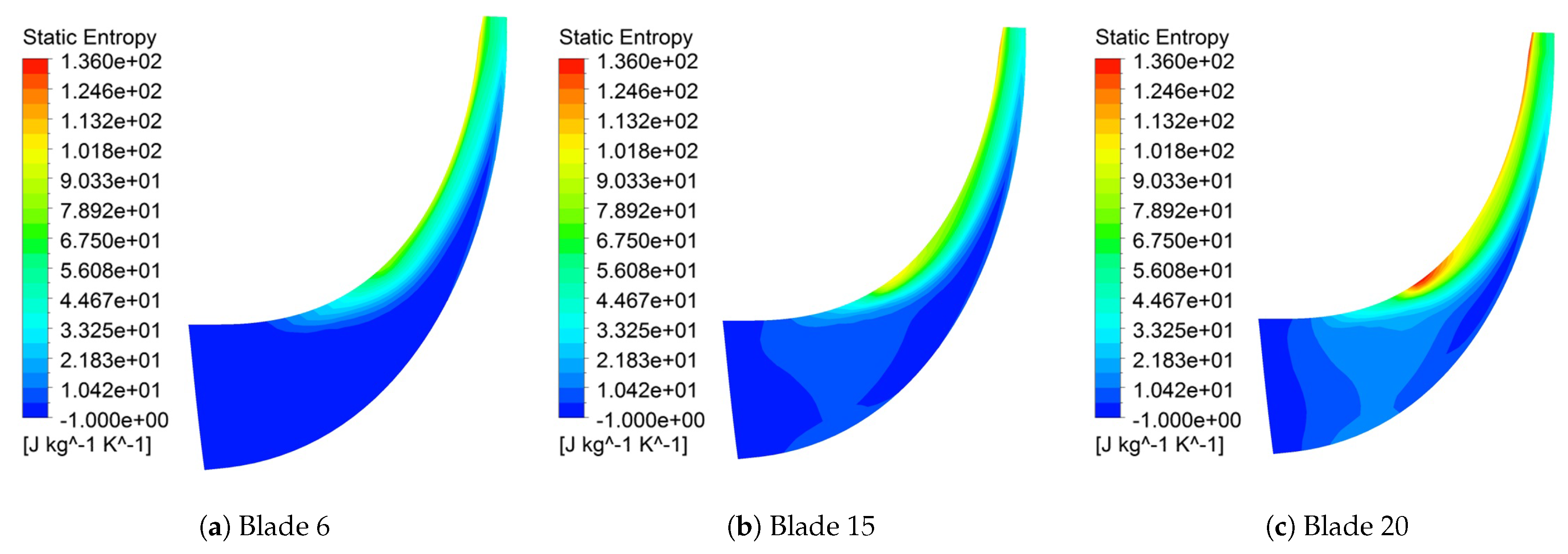
3.1.1. Without Splitter Blades
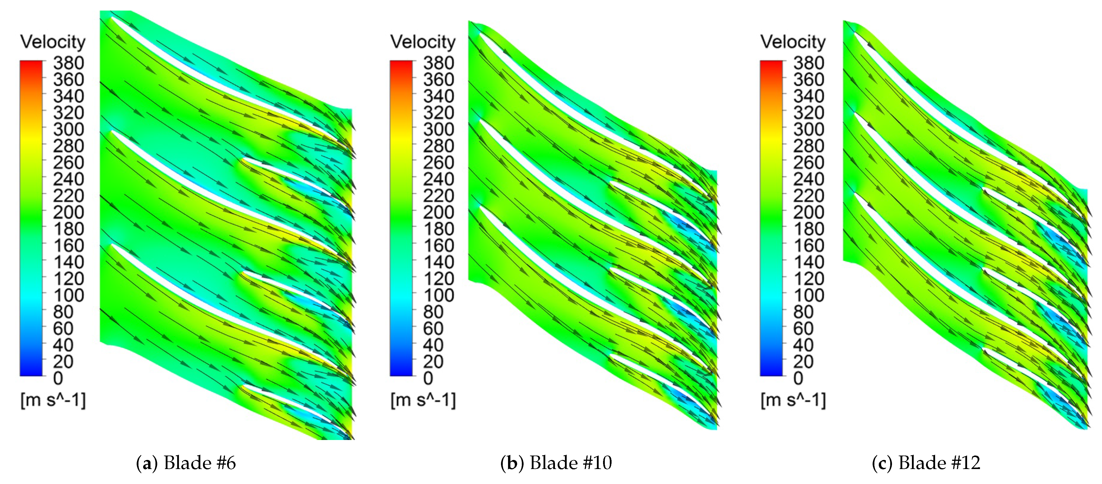
3.1.2. With Splitter Blades
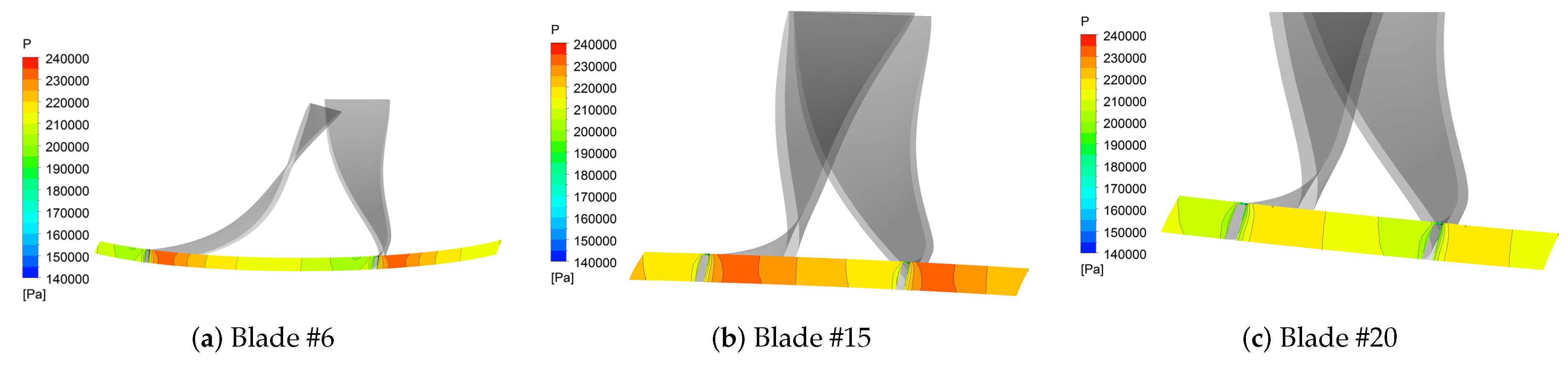
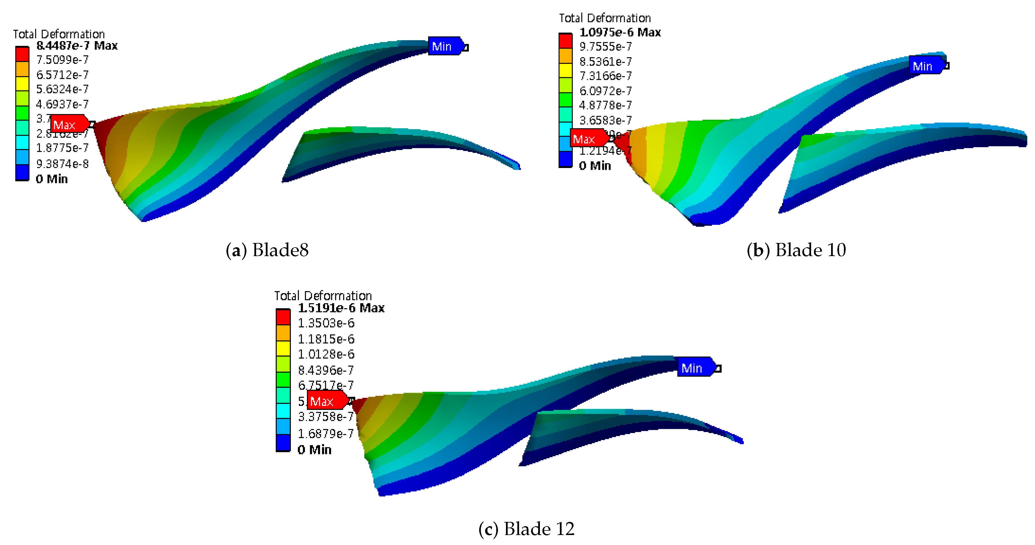
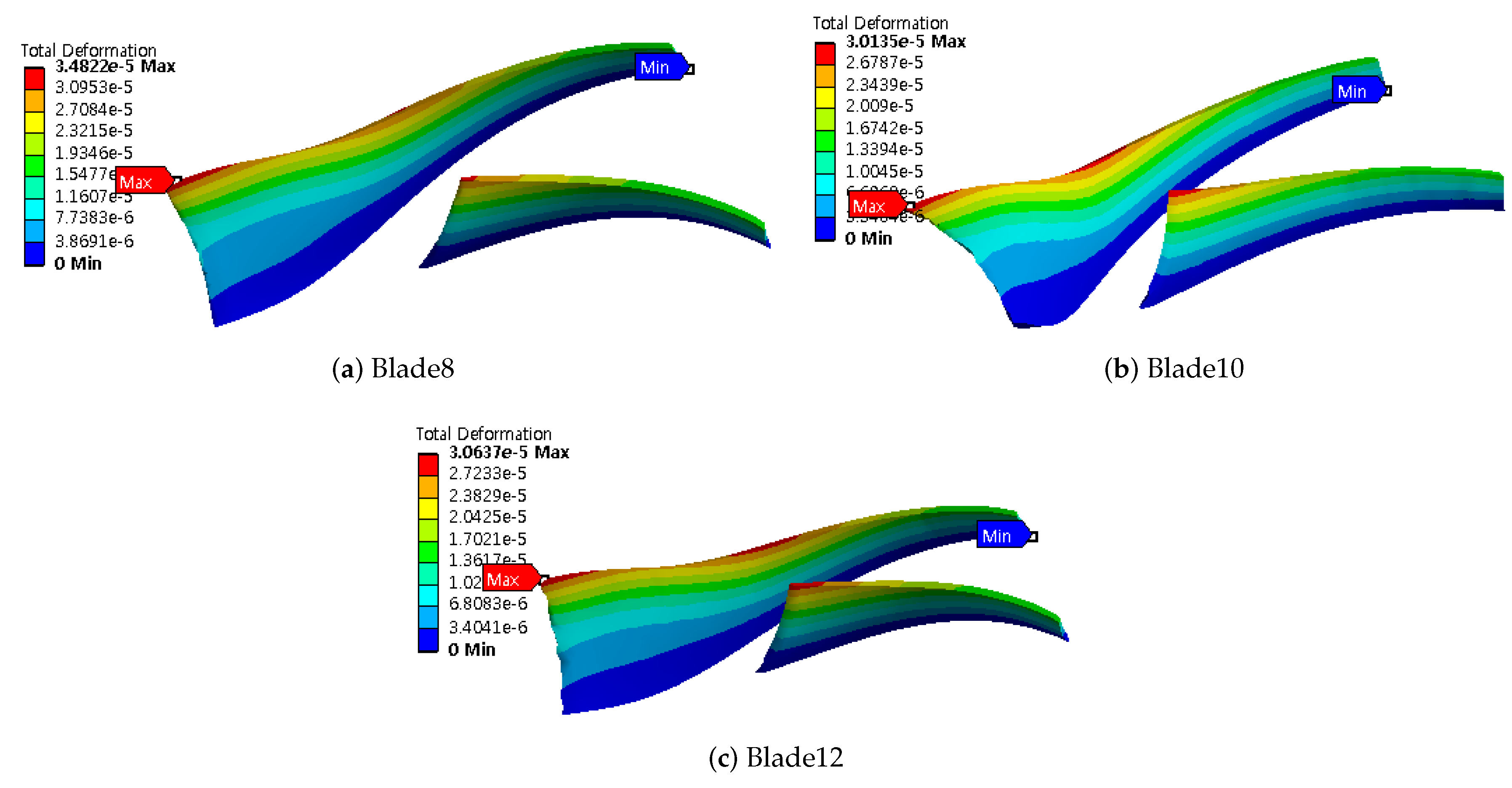
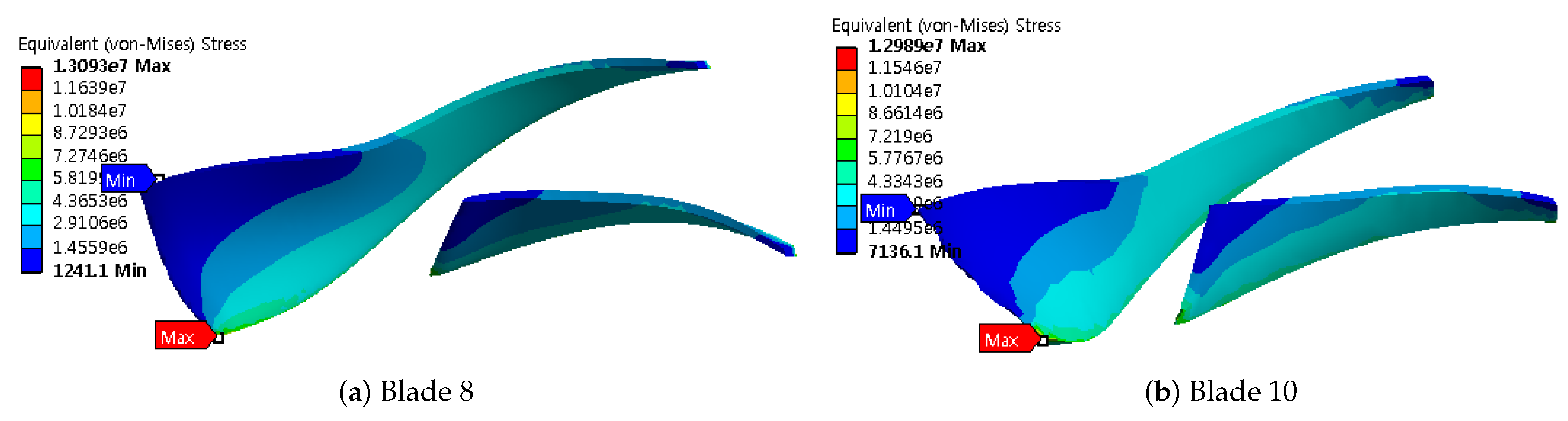
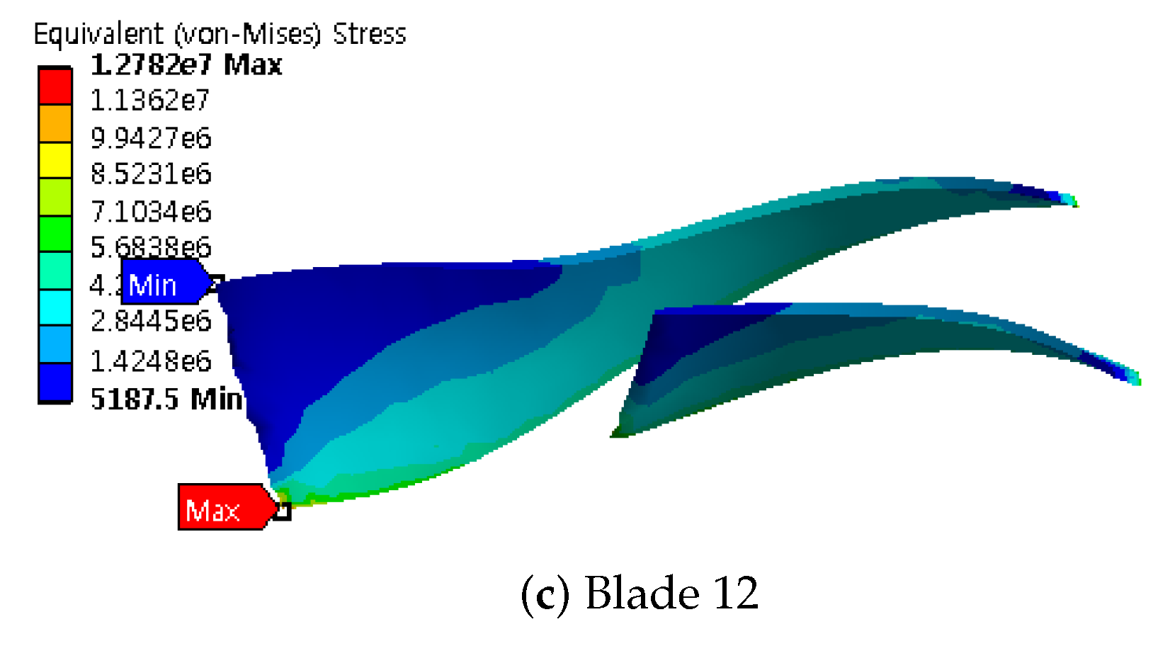
3.2. Fluid–Structure Interaction
4. Conclusions
Author Contributions
Acknowledgments
Conflicts of Interest
References
- Mojaddam, M.; Pullen, K. Optimization of a Centrifugal Compressor Using the Design of Experiment Technique. Appl. Sci. 2019, 9, 291. [Google Scholar] [CrossRef]
- Bardelli, M.; Cravero, C.; Marini, M.; Marsano, D.; Milingi, O. Numerical Investigation of Impeller-Vaned Diffuser Interaction in a Centrifugal Compressor. Appl. Sci. 2019, 9, 1619. [Google Scholar] [CrossRef]
- Benra, F.K.; Dohmen, H.J.; Pei, J.; Schuster, S.; Wan, B. A comparison of one-way and two-way coupling methods for numerical analysis of fluid-structure interactions. J. Appl. Math. 2011, 2011. [Google Scholar] [CrossRef]
- Gu, Y.; Pei, J.; Yuan, S.; Xing, L.; Stephen, C.; Zhang, F.; Wang, X. Effects of blade thickness on hydraulic performance and structural dynamic characteristics of high-power coolant pump at overload condition. Proc. Inst. Mech. Eng. Part A J. Power Energy 2018, 232, 992–1003. [Google Scholar] [CrossRef]
- Ying, Q.; Zhuge, W.; Zhang, Y.; Zhang, L. Design Optimization of A Small Scale High Expansion Ratio Organic Vapour Turbo Expander for Automotive Application. Energy Procedia 2017, 129, 1133–1140. [Google Scholar] [CrossRef]
- Gong, C.D.; Lee, H.S.; Kim, I.K. Aerodynamic and Structural Design of A High Efficiency Small Scale Composite Vertical Axis Wind Turbine Blade. Trans. KSAS 2011, 39, 758–765. [Google Scholar] [CrossRef] [Green Version]
- Drewczynski, M.; Solution, G.E.; Rzadkowski, R. A stress analysis of a compressor blade in partially blocked inlet condition. Proc. IMechE Part G J. Aerosp. Eng. 2015, 1–19. [Google Scholar] [CrossRef]
- Kang, H.S.; Kim, Y.J. Optimal design of impeller for centrifugal compressor under the influence of one-way fluid-structure interaction. J. Mech. Sci. Technol. 2016, 30, 3953–3959. [Google Scholar] [CrossRef]
- Zhao, H.; Deng, Q.; Zheng, K.; Zhang, H.; Feng, Z. Numerical Investigation on the Flow Characteristics of a Supercritical CO2 centrifugal compressor. In Proceedings of the ASME Turbo 2014: Turbine Technical Conference and Exposition, Düsseldorf, Germany, 16–20 June 2014; pp. 1–10. [Google Scholar] [CrossRef]
- Schneider, A.; Will, B.C.; Böhle, M. Numerical evaluation of deformation and stress in impellers of multistage pumps by means of fluid structure interaction. In Proceedings of the ASME 2013 Fluids Engineering Division Summer Meeting, Incline Village, NV, USA, 7–11 July 2013; pp. 1–10. [Google Scholar]
- Kobayashi, K.; Ono, S.; Harada, I.; Chiba, Y. Numerical Analysis of Stress on Pump Blade by One-Way Coupled Fluid-Structure Simulation. J. Fluid Sci. Technol. 2010, 5, 219–234. [Google Scholar] [CrossRef] [Green Version]
- Piperno, S.; Farhat, C.; Larrouturou, B. Partitioned procedures for the transient solution of coupled aroelastic problems Part I: Model problem, theory and two-dimensional application. Comput. Methods Appl. Mech. Eng. 1995, 124, 79–112. [Google Scholar] [CrossRef]
- Kang, H.S.; Kim, Y.J. A study on the multi-objective optimization of impeller for high-power centrifugal compressor. Int. J. Fluid Mach. Syst. 2016, 9, 143–149. [Google Scholar] [CrossRef]
- Gong, B.L.; Jia, X.J.; Wang, G.C.; Liu, Z.W. Study on application of CAE in a centrifugal compressor impeller. Adv. Mater. Res. 2013, 787, 594–599. [Google Scholar] [CrossRef]
- Lee, K.; Huque, Z.; Kommalapati, R.; Han, S.E. The Evaluation of Aerodynamic Interaction of Wind Blade Using Fluid Structure Interaction Method. J. Clean Energy Technol. 2014, 3, 270–275. [Google Scholar] [CrossRef]


| Parameters | Details |
|---|---|
| Rotational velocity | 73,000 rpm |
| Impeller outer diameter | 123 mm |
| Impeller width | 3.6 mm |
| Impeller suction diameter | 51.4 mm |
| Impeller hub diameter | 15 mm |
| Discharge diameter | 129.16 mm |
| Discharge width | 2.99 mm |
| Length in axial direction | 86.63 mm |
| Axial length of main blades | 36.60 mm |
| Axial length of splitter blades | 17.10 mm |
| Material Property | Details |
|---|---|
| Modulus of elasticity | 114 GPa |
| Poisson’s ratio | 0.33 |
| Density | 4430 kg/m |
| Tensile strength, ultimate | 1170 MPa |
| Tensile strength, yield | 1100 MPa |
| Blade #8 | Blade #10 | Blade#12 | ||||
|---|---|---|---|---|---|---|
| No Splitter | Splitter | No Splitter | Splitter | No Splitter | Splitter | |
| Rotation Speed (radian s) | ||||||
| Mass Flow Rate (kg s) | 0.3000 | 0.3000 | 0.3000 | 0.3000 | 0.3000 | 0.3000 |
| Inlet Volume Flow Rate (m s) | 0.2361 | 0.2512 | 0.2427 | 0.2536 | 0.2464 | 0.2535 |
| Input Power (W) | 40,969.9 | 46,516.6 | 43,550.8 | 47,486.3 | 45,133.3 | 47,743.9 |
| Work Input Coefficient | 0.6663 | 0.7109 | 0.6892 | 0.7189 | 0.7034 | 0.7230 |
| Total Pressure Ratio | 3.4691 | 3.7317 | 3.5866 | 3.7743 | 3.6542 | 3.7771 |
| Total Temperature Ratio | 1.4897 | 1.5225 | 1.5065 | 1.5284 | 1.5169 | 1.5313 |
| Total Isentropic Efficiency (%) | 87.8024 | 88.0925 | 87.5507 | 88.0186 | 87.2671 | 87.6186 |
| Total Polytropic Efficiency (%) | 89.7042 | 90.0684 | 89.5477 | 90.0228 | 89.3419 | 89.6915 |
© 2019 by the authors. Licensee MDPI, Basel, Switzerland. This article is an open access article distributed under the terms and conditions of the Creative Commons Attribution (CC BY) license (http://creativecommons.org/licenses/by/4.0/).
Share and Cite
Jebieshia, T.R.; Raman, S.K.; Kim, H.D. Aerodynamic and Structural Characteristics of a Centrifugal Compressor Impeller. Appl. Sci. 2019, 9, 3416. https://doi.org/10.3390/app9163416
Jebieshia TR, Raman SK, Kim HD. Aerodynamic and Structural Characteristics of a Centrifugal Compressor Impeller. Applied Sciences. 2019; 9(16):3416. https://doi.org/10.3390/app9163416
Chicago/Turabian StyleJebieshia, T R, Senthil Kumar Raman, and Heuy Dong Kim. 2019. "Aerodynamic and Structural Characteristics of a Centrifugal Compressor Impeller" Applied Sciences 9, no. 16: 3416. https://doi.org/10.3390/app9163416