1. Introduction
Worm gears find extensive use in various industries and have a significant share in the gear-and-drives market. They enable the attainment of significant gear ratios, reaching up to 300:1 in a single gear stage. These gears are capable of transmitting motion at a 90° axis angle, have a compact design, operate quietly, and are commonly self-locking, preventing reverse driving [
1].
The load-capacity calculation of worm gears is standardised in ISO/TS 14521 [
2] and DIN 3996 [
3]. These standards cover calculations of load capacity for worm gears, such as wear, pitting, worm-shaft bending, tooth breakage, and temperature.
Höhn [
4] developed a method that allows the determination and optimisation of a worm and worm-gear contact pattern. This method is based on a point-by-point simulation of a worm and worm gear that considers the manufacturing process. Simon [
5] developed a method for computer-aided loaded-tooth contact analysis. This method can analyse different types of cylindrical worm gears, and it covers contact of the theoretical line and contact in point. Sharif [
6] presented a wear model for the prediction of wear patterns. This model is based on an electrohydrodynamic lubrication that provides wear distribution on the tooth surfaces during meshing.
Paschold [
7] presented a method for determining the efficiency and heat balance of gearboxes with worm gears. For this purpose, he developed new approaches for the calculation of losses under load and without load. Also, he developed new algorithms for normalisation and node linking and customised formulas for thermal resistance. Roth [
8] presented a numerical temperature simulation for worm gears that considers transient multidimensional heat transfer and local frictional loading due to contact. He gave a simplified calculation of worm-gear contact temperature. Stahl [
9] presented a new model for determining pitting load resistance that considers contact patterns. Hitcher [
10] carried out a numerical simulation to study the influence of cutting parameters and to find the optimal manufacturing procedure. Daubach [
11] developed a simulation model for the abrasive wear of worm gears based on the energetic wear equation. This simulation model includes tooth contact analysis and tribological calculation to determine friction and wear. Tošić investigated the thermal effects of slender EHL contacts in the case of disc–disc contact [
12] and contact of worm gears [
13]. He introduced a numerical procedure for the investigation of the transient thermal EHL contact of worm gears with nonconjugated meshing action. He used FEM by implementing the thermal elastohydrodynamic lubrication model.
Chernets [
14] evaluated a computation method for worm gears with Archimedean and involute worms in operation. His approach is based on contact pressures, wear at worm-gear teeth, gear life, and sliding speed. Jbily [
15] proposed a numerical model for predicting the wear of worm gears. This numerical model is based on Archard’s wear formulation and considers the influence of lubrication on the local wear coefficient, which depends on the minimum lubricant film and the amplitude of surface roughness. Oehler [
16] developed a new calculation method for the prediction of the efficiency of worm-gear drives that is compatible with DIN 3996 and that could be incorporated into standard calculations. His research is based on simulations and validated by experiments, and his approach allows engineers to compare different drivetrain concepts regarding efficiency. Miltenovic [
17] investigated the thermal design and prediction of the whole worm-gear drive using FEM.
Li [
18] proposed a scuffing model for spur-gear contacts. For this purpose, a heat transfer formulation was devised to evaluate gear bulk temperature. Bulk temperature was used for EHD modelling to determine tribological behaviour within the contact zone. Yanzhong [
19] investigated the friction heat generation during meshing of spiral bevel gears for different pinion machine setting parameters. He used FEM to compare models generated for different pinion machine setting parameters. Castro [
20] investigated the influence of mass temperature on gear scuffing and developed a new scuffing parameter for gears lubricated with mineral base oils. The scuffing parameter is based on the heat power intensity for mass temperature calculations. Mieth [
21] presented a method for stress calculation on bevel gears with FEM influence vectors, in which these vectors allowed the consideration of the tooth geometry and gear-body constraint in the load distribution.
Wang [
22] proposed a methodology for optimising the loaded contact pattern of spiral bevel and hypoid gears that solved the optimisation with a surrogate kriging-based model. This model considered the contact pattern under load, loaded transmission error, contact strength, and bending strength. The paper presented a numerical example that reduced the loaded transmission error by 30.3% by decreasing the maximum contact stress and root bending stress.
Marciniec [
23] compared numerical methods to determine the contact pattern of Gleason-type bevel gears. He used a mathematical model of tooth contact analysis and FEM to simulate the load. Li [
24] analysed the thermal characteristics of spur/helical gear transmission using FEM. He derived a calculation formula of the frictional heat flux and convective heat transfer coefficient which considers different surfaces of the gear tooth. His approach reveals the temperature distribution on the tooth flank and provides theoretical guidance for gear optimisation and anti-scuffing capability. Rong [
25] proposed innovative digital twin modelling for loaded contact pattern-based grinding.
De Bechillion [
26] investigated scuffing with an experiment by using twin-disc contact with an experimental methodology to assess the initiation of gear scuffing. Experiments were conducted with nitrided steel and synthetic oil. He identified oil-film thickness as the key parameter, also showing that a variety of operating conditions influence scuffing as well. Scuffing could also be triggered by rising bulk temperatures.
2. Scuffing in Worm Gears
According to ISO 14635-1, scuffing is defined as “a particularly severe form of damage to the gear-tooth surface in which seizure or welding together of areas of tooth surface occur, due to absence or breakdown of a lubricant film between the contacting tooth flanks of mating gears” [
27]. Typical reasons for the occurrence of scuffing are high temperatures and high pressure, while scuffing also most likely occurs in the case of high surface velocities. Scuffing depends on various properties, such as gear materials, lubricants, the roughness of mating surfaces, sliding velocities, and load.
The analysis of these properties shows the following:
In the case of a worm-gear pair, the typical material for a worm is hardened steel, while a worm gear is usually made of bronze. The reason behind this lies in the fact that this material pair has the highest resistance to the occurrence of scuffing even though bronze is more expensive compared to other steels. The dissimilarity in materials reduces friction and therefore increases scuffing resistance.
The sliding velocity is very high in worm gears because they transfer motion through a 90° axis angle. This is a factor that significantly affects the occurrence of scuffing, and it cannot be influenced.
When it comes to lubrication, it is recommended to lubricate worm gears in extreme operating environments, such as certain oils, with extreme-pressure (EP) additives, so as to increase resistance to the absence or breakdown of a lubricant film, therefore the occurrence of reducing scuffing.
The roughness of mating surfaces directly influences the occurrence of scuffing; the rougher the surfaces, the higher the likelihood of occurrence of scuffing.
This analysis shows that scuffing is crucial for the design of worm gears, and it requires a significant amount of research to control the occurrence of scuffing and therefore increase scuffing load capacity. The idea of this paper is to investigate the influence of the contact pattern of a worm gear set on friction heat generation during meshing using FEM simulation and to check to what extent it can influence heat generation and, therefore, the occurrence of scuffing.
The contact pattern between a worm and worm gear in a standardly manufactured and properly mounted gear pair should be in the middle and across the worm-gear tooth. A worm gear is manufactured with a helix angle, and this means that the geometry of the worm-gear tooth differs at the input and output sides.
For the FEM simulation of a worm gear set, the referenced geometry according to ISO/TS 14521 was chosen [
2]. Changing the pinion machine setting parameters can influence the contact pattern and therefore change the contact shape and the contact heat flux. It is then possible to find optimal machine setting parameters from the aspect of minimising the heat flux and, thus, increasing the efficiency of transmission. In this paper, direct-coupled field thermal–structural FEM simulation is used to investigate the difference of the contact heat flux at the contact pattern for standard-production machine settings and those that shift contact patterns for the same value into the inlet and outlet side of the worm-gear tooth. The results of this paper can be used by worm-gear designers to decrease the occurrence of scuffing by changing the contact pattern. This paper also shows the potential of contact patterns to increase load capacity.
3. Geometry
The geometry of the referenced gear according to ISO/TS 14521 [
2] was used for the simulation.
Table 1 lists the worm-gear pair’s geometry, materials, and thermal data.
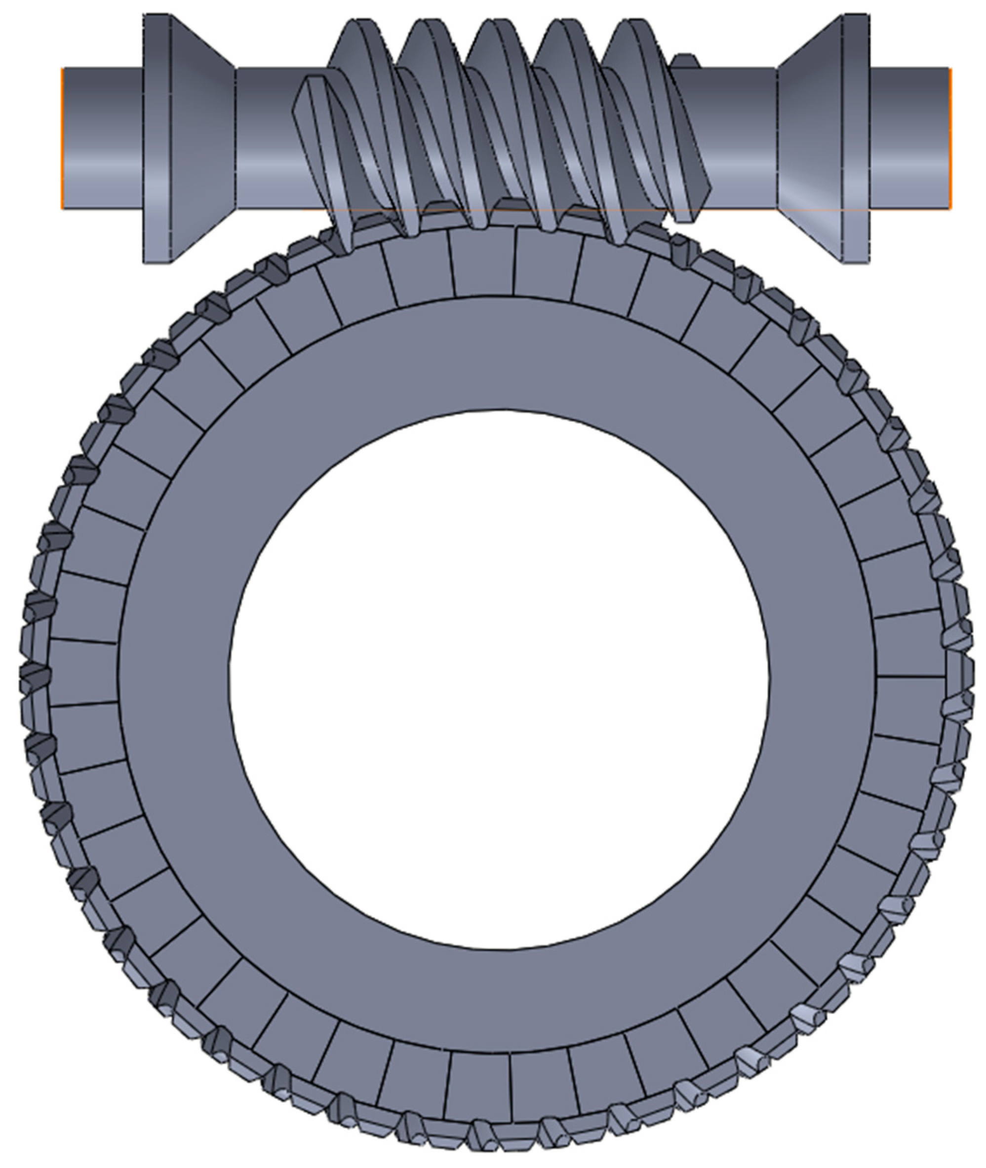
Figure 1 represents the worm-gear set with the referenced geometry listed in
Table 1. The structures of the worm and worm-gear sub-solids were designed to facilitate the generation of a uniform high-quality mesh for finite element analysis.
The whole gear pair was generated in SolidWorks and then transferred to Ansys 19.2 for further analysis. For a better understanding of the worm-gear contact pattern, a barrel-shaped tooth of the worm-gear tooth with 10 μm was introduced. The correct geometry of the worm and worm-gear teeth as well as the contact pattern was created using TRABI 8.0 software [
27]. In order to generate correct geometry, special attention was given to the contact flanks. These flanks were created by first entering individual points generated in TRABI and then creating the curves based on those points that we used for the generation of surfaces, and by creating solids that we based on those surfaces (
Figure 2).
4. Contact Pattern
The gear-tooth contact pattern is the gear axial location used to achieve the desired position of the gear in order to provide an initial contact pattern to carry the design load of the gear set. The standard calculation for manufacturing worm gears yields a contact pattern with a calculated contact pattern in the middle. The authors chose to generate three models that could be used to compare the dependence of contact patterns on friction heat generation. The machine settings for the worm gear are given in
Table 2.
The typical method for manufacturing worm gears is hobbing using a hob or cutting tool. The cutting tool for worm gears is similar to the gear with which the worm gear will mate.
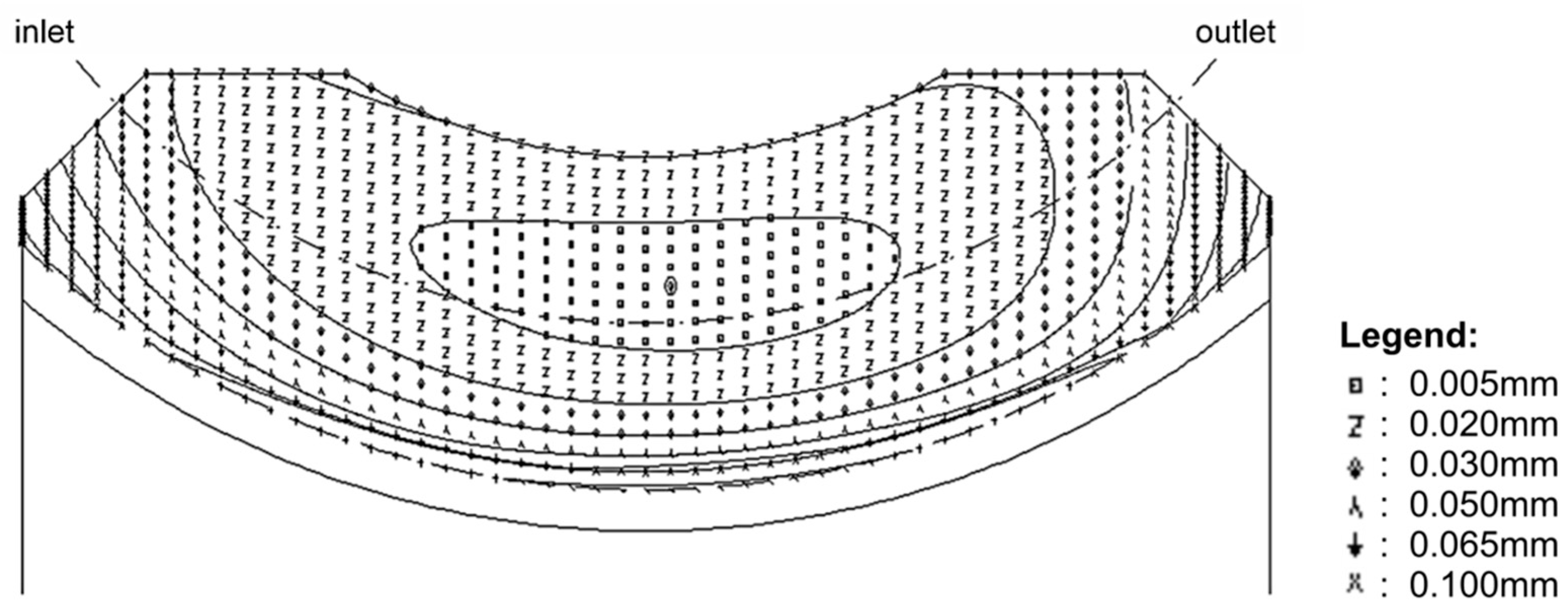
Figure 3 shows the contact pattern of a worm gear with the contact in the middle, as is the case with regular machine setting parameters.
Figure 4 shows the contact pattern at a worm gear that is shifted left to the outlet side, while
Figure 5 shows the contact pattern at a worm gear that is shifted right to the inlet side. The difference is a machine setting pressure angle that is increased to 0.0518 and equals 0.07 in the case in
Figure 4. In the case when the contact pattern is shifted to the inlet side, this parameter is decreased to −0.0518, as shown in
Figure 5.
5. Finite Element Modelling and Simulation
Direct-coupled transient thermal–structural analysis was used to assess the heat flux distribution of the worm-gear pair. The modelling and solving of the finite element model were conducted using ANSYS 19.2 software.
The rate of frictional dissipation in the contact elements was evaluated using the default ANSYS equation [
28]:
where:
FHTG—the dissipation factor, which takes into account the part of friction energy that is converted into heat;
τ—the equivalent stress that depends on the contact pressure and the friction coefficient;
v—the relative sliding velocity.
All frictional dissipated energy was considered to be converted into heat, and the distribution of friction-generated heat between the worm and the worm gear was considered equal.
The numerical analysis was carried out via three main steps according to the operating conditions listed in
Table 3. The model’s boundary conditions are defined in
Figure 6. The first step was the introduction of the axial force load to establish proper contact between the worm and the wheel. The second step was to increase the speed of the worm drive to the operating speed of 1500 min
−1. The third step was used to assess the heat flux distribution in the operating conditions. The analysis time of the third step that corresponded to the actual operating conditions was 0.4 s, which enabled the gear pair to rotate for several mesh cycles and to achieve consistent results, showing dynamic changes in temperature and contact stress.
The central rotation points of the pinion and gear were fixed to the inner side of the worm and wheel. The geometry of the worm and wheel was sliced to obtain simple bodies for optimising the mesh size and quality. The final mesh contained 24,703 elements with 27,926 nodes. The mesh of the worm-gear tooth is shown in
Figure 7, and the contact surfaces of the worm and worm gear are shown in
Figure 8. The mesh was generated with higher-order elements (SOLID226 [
29]) in order to accurately capture the geometry of the worm and wheel. A mesh sensitivity test was performed, and mesh sizing of 1 mm on tooth flanks was adopted to ensure that contact pressure results did not differ by more than 5%.
The friction coefficient value necessary for the definition of contact pairs was determined based on ISO/TS 14521. The friction coefficient, i.e., mean tooth friction number, as defined in the standard was calculated as:
In Equation (2), the size factor
YS takes into account the influence of the centre distance via the following formula:
The geometry factor
YG considers the gear geometry’s influence on the lubricating gap thickness. It depends on the characteristic value for mean lubrication gap width
h* = 0.0692 that is calculated according to ISO 14521.
The material coefficient
YW takes into account the material of the wheel, and for the materials that are used in this paper, the coefficient was selected as
YW = 0.95 from DIN EN 1982 [
3]. The roughness factor
takes into account the influence of the surface roughness of the worm flank, and for
Ra1 = 0.6, it is calculated as follows:
The base friction number depends on the oil type and the material of the wheel, and for oil-bath lubrication and oil ISO-VG 220 [
3] with synthetic oil based on Polyglycol, the following equation applies:
The sliding velocity on the mean circle (m/s) is calculated as follows:
The heat transfer coefficient of the wheel (W/m
2/K) is calculated as follows:
where
ck = 1 is the immersion factor for the wheel, and for the immersed wheel, a value of 1 was used (for oil-bath lubrication) and
n1 is speed of worm.
6. Results
Figure 9 shows the pressure distribution on the worm-gear teeth for all three cases. It shows that the pressure is in the centre for the case with the standard contact pattern (a) or slightly to the left (b), corresponding to the shift to the outlet side, or to the right (c), corresponding to the contact pattern shift to the inlet side.
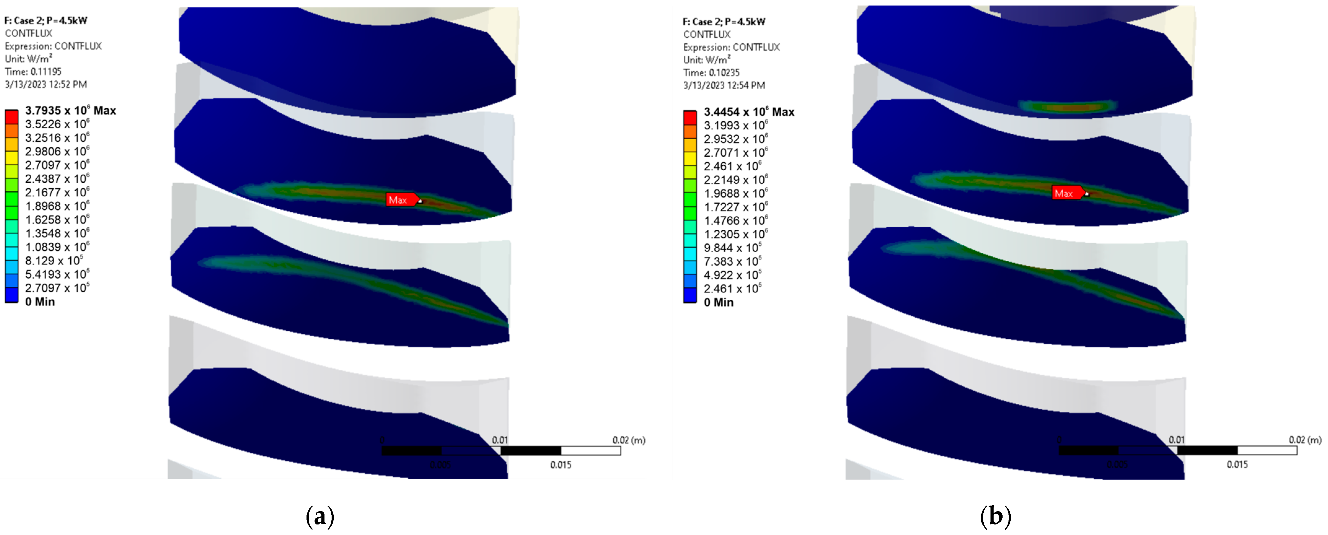
Figure 10 shows the heat flux distribution on the worm-gear teeth with the standard contact pattern on two and three teeth. In this case, it is clear that the maximal heat flux is approximately in the middle of the gear teeth, as expected from the contact pressure results.
Figure 11 shows the heat flux distributions on the worm-gear teeth with the contact pattern shifted to the outlet side on two and three teeth. In this case, it is clear that the distribution of the heat flux as well as the maximal heat flux are on the right part of the gear teeth.
Figure 12 shows the heat flux distribution on the worm-gear teeth with the contact pattern shifted to the inlet side on two and three teeth. In this case, it is clear that the distribution of heat flux as well as the maximal heat flux are on the left part of the gear teeth.
Figure 13 shows a comparison of the average heat flux on the worm-gear teeth over the operation time of 0.4 sec. The average heat flux for the contact surface had the normal variant value of 21,888.3 W/m
2. For the worm-gear variant where the contact pattern was shifted to the inlet side, the average heat flux was 21,040.1 W/m
2, and for the variant where the contact pattern was shifted to the outlet side, the average heat flux was 23,440.3 W/m
2. This means that when compared to the standard contact pattern, the average heat flux for the worm gear with the contact pattern shifted to the inlet side was 3.76% lower, while it was 7.09% higher for the contact pattern that was shifted to the outlet side.
7. Conclusions
This paper investigated the influence of the contact pattern of a worm-gear set on the friction heat generated in the contact between the worm and the worm-gear teeth. Using FEM simulation, three cases of worm-gear pairs were investigated with different pinion machine setting parameters. The referent variant was the normal contact pattern according to the standard, with two additional variants in which the contact pattern was shifted either to the inlet or the outlet side of the worm-gear tooth.
The results of the FEM analysis confirmed the position of the contact pattern on the worm-gear tooth for all three cases. The average heat flux had the highest values when the contact pattern was shifted to the outlet side, and it was 7.09% higher than for the standard contact pattern. The worm-gear tooth with the contact pattern shifted to the inlet side had a value of the average heat flux that was 3.76% lower than the case with the standard contact pattern.
The results indicate that shifting the contact pattern to the inlet side generates slightly less heat during operation. Therefore, such a gear pair will be less susceptible to the occurrence of scuffing and have a higher load capacity. On the other hand, shifting the contact pattern to the outlet side will result in opposite effects—lower efficiency and load capacity.
Further research should go in the direction of experimental verification of the results that are presented in this paper. It would be beneficial to find an efficient way to collect thermal data during the operation of experiments since the thermal distribution on the surfaces in contact is very important for the occurrence of scuffing.

 ,
, 


