Article

A Study on the Influence of Dewatering in the Excavation of Adjacent Tunnels under Lateral Soil Effects

1
Nanchang Rail Transit Group Limited Corporation, Nanchang 330013, China
2
The Key Laboratory of Performance Monitoring Protecting of Rail Transit Infrastructure, East China Jiaotong University, Nanchang 330013, China
3
College of Railway Engineering, Hunan Technical College of Railway High-Speed, Hengyang 421200, China
*
Author to whom correspondence should be addressed.
Appl. Sci. 2024, 14(1), 102; https://doi.org/10.3390/app14010102
Submission received: 17 October 2023 / Revised: 4 December 2023 / Accepted: 20 December 2023 / Published: 21 December 2023
(This article belongs to the Special Issue Advanced Technologies in Deep Excavation)

Abstract

:
The dewatering of foundation pits leads to changes in the water level and effective stress within the surrounding strata. When existing tunnels are present within the dewatering influence zone, the impact of dewatering on these tunnels cannot be ignored. The Vlasov foundation beam model was used to simulate the interaction between the tunnel and the soil, and the key parameters of the model were precisely investigated. In addition, the constraining effect of the lateral soil on the tunnel was also considered. By integrating the principles of effective stress and Dupuit’s assumption, in this work we calculated the additional load on the tunnel caused by foundation pit dewatering, which was then applied to determine the tunnel stress and deformation induced by dewatering. The accuracy of this approach is validated through comparative analysis with finite element results. Furthermore, the relationships between the permeability coefficient (kt), the spacing (d) between the tunnel and the dewatering well, the water level drop (sw), and tunnel stress and deformation were further studied. The key findings are summarized as follows. Firstly, accounting for lateral soil effects enhances computational accuracy. Secondly, an increase in soil kt leads to a greater tunnel settlement with relatively minor changes in bending moments. Thirdly, as d increases, both tunnel settlements and bending moments decrease. Additionally, as the water level dropped from 10 m to 30 m, the maximum additional stress on the tunnel increased by 94.50%, and the settlement increased by 127.43%. Consequently, it is essential to pay close attention to the tunnel segment nearest to the water level.

1. Introduction

In geotechnical engineering, dewatering methods are frequently employed to enhance construction conditions for various engineering applications, including excavating foundation pits and reinforcing soft soil foundations. Nonetheless, dewatering may result in a reduction in the water level in the adjacent strata and an associated increase in the effective stress within the soil [1,2,3,4]. When an active shield tunnel is situated within the influence zone of dewatering activities, the reduction in water levels induces an increment in the effective stress within the surrounding soil. This leads to an additional load on the tunnel and imparts adverse consequences, as documented in previous studies [5,6,7,8,9]. As pivotal components of urban transportation infrastructure, subway shield tunnels carry substantial economic and property implications in the event of inadequate maintenance or protective measures, or even minor negligence. Therefore, it is imperative to conduct an in-depth analysis of tunnel deformation resulting from foundation pit dewatering to bolster our ability to monitor and safeguard against tunnel distortion.
Currently, a significant body of research has been dedicated to the investigation of tunnel deformation resulting from subterranean dewatering. Zheng et al. [10] conducted a finite element simulation to investigate the influence of pressure reduction and confined layer dewatering on the structural integrity of existing shield tunnels. Wang et al. [11] developed a numerical model to examine the effects of underground dewatering on nearby subway tunnels. In accordance with practical engineering applications, Wang et al. [12] employed the finite element method to assess the structural impact of foundation pit dewatering on tunnels. Additionally, Nie [13] and Li [14] conducted numerical calculations to comprehensively analyze and investigate deformation and stress patterns in existing tunnels under various underground dewatering scenarios. Yang et al. [15] deduced the analytical solution of the vertical displacement of adjacent tunnels under pre-dewatering disturbance by using a two-stage analysis method. Xu et al. [16] utilized a two-stage analytical method to derive solutions for assessing the deformation of adjacent pipelines resulting from single-well dewatering. Furthermore, ZHANG et al. [17] evaluated tunnel deformation directly beneath foundation pits during excavations and dewatering, applying the Pasternak foundation beam model. Their findings underscore the significance of recognizing the impact of dewatering on underlying tunnels.
In theoretical studies concerning the deformation of shield tunnels, the elastic foundation beam model is a widely employed framework for simulating the interaction between tunnels and the surrounding soil. For the methods, the shear layer’s shear modulus and the coefficient of the subgrade modulus strongly influence simulation results, which can explain their crucial roles in determining the ability of the elastic foundation to withstand shear deformation and compression deformation. However, these two parameters are often determined by various empirical equations [18,19,20,21], which may fail to accurately portray the interaction between the soil and the tunnel and result in subjective or biased results. Hence, achieving a more accurate estimation of these two parameters is crucial for the precise prediction of existing tunnel settlements when simulating the soil–tunnel interaction. Despite that, the Vlasov foundation beam model [22] offers a comprehensive approach that not only considers the continuity of soil deformation within the foundation but also provides a theoretically sound method for determining model parameters, demonstrating notable calculation accuracy [23]. Furthermore, the interaction between underground structures and the surrounding soil is inherently a three-dimensional problem. In addressing this issue, it is imperative to consider not only the influence of the foundation beneath the structure but also the constraints imposed on its deformation by lateral soil [24]. However, the existing analytical formulas are derived from the plane strain problem, ignoring the effect of lateral soil on the tunnel, which will inevitably affect the accuracy of the calculation results [25]. Building upon this premise, this study utilizes the Vlasov foundation beam model while incorporating the effects of lateral soil, as previously researched. Consequently, it derives an analytical solution for predicting the deformation of adjacent shield tunnels subject to foundation pit dewatering. The validation of the proposed method’s accuracy is achieved through a comparison with finite element simulation results. Additionally, this research explores the interrelationship among the permeability coefficient (kt), the distance between the tunnel and the dewatering well (d) and the drawdown of water level (sw) in relation to tunnel stress and deformation.

2. The Formulation and Resolution of Equations for Tunnel Load and Deformation

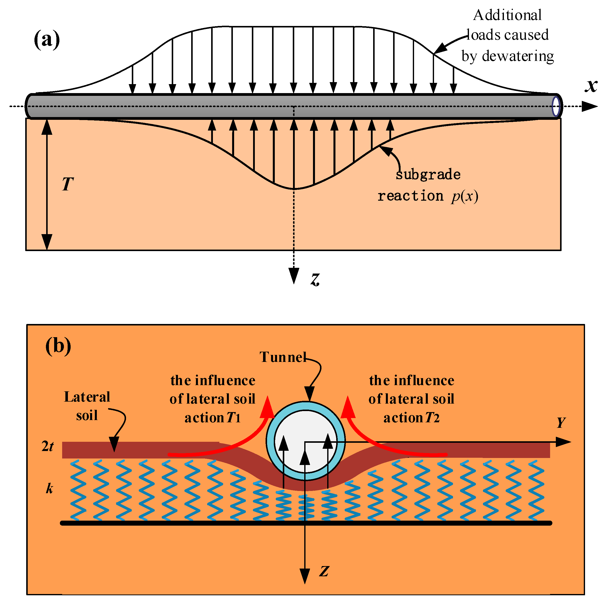
2.1. The Formulation of Equations Neglecting the Influence of Lateral Soil Action

Figure 1 presents a simplified schematic representation of the computational model used in this paper, wherein the tunnel is modelled as a Euler–Bernoulli beam supported by a Vlasov foundation, replicating the interaction between the tunnel structure and the surrounding soil.
In the Vlasov foundation model, the relationship between the foundation reaction p(x) and the tunnel settlement u(x) is given follows:
p ( x ) = k u ( x ) 2 t d 2 u ( x ) d 2 x
where k is the foundation reaction coefficient, and t is the soil layer shear coefficient, representing the degree of soil deformation continuity. These two can be calculated using the following formulas:
k = ( 1 v ) E s ( 1 + v ) ( 1 2 v ) 0 T ( d h ( z ) d z ) 2 d y
2 t = E s 2 ( 1 + v ) 0 T h 2 ( z ) d y
where Es represents the elastic modulus of the soil, T stands for the thickness of the elastic foundation layer, and is set to T = 2.5D in this work [19], D denotes the tunnel diameter, and h(z) corresponds to the attenuation function within the Vlasov foundation model, which accounts for the diminishing effect of the foundation soil along the deformation direction to determine the values of k and t. Typically, this function can manifest as either a linear or exponential relationship. For the purposes of this paper, h(z) is defined as h(z) = (Tz)/z.
On such basis, the force balance relationship of the tunnel under the influence of dewatering determines the settlement equation of the tunnel as follows:
E I d 4 u ( x ) d x 4 + p ( x ) D = q ( x ) D
where EI represents the bending stiffness of the tunnel, with E being the elastic modulus of the whole tunnel, and I denoting the moment of inertia of the tunnel cross-section. Furthermore, q(x) represents the additional load induced by dewatering. Substituting Equation (1) into Equation (3) gives:
E I d 4 u ( x ) d x 4 2 t D d 2 u ( x ) d x 2 + k D u ( x ) = q ( x ) D

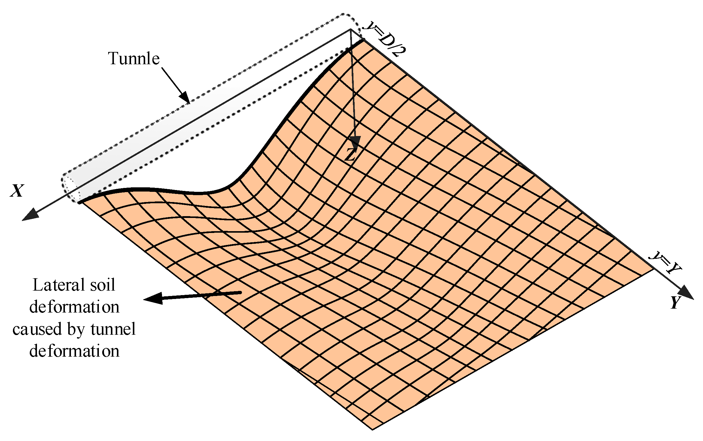
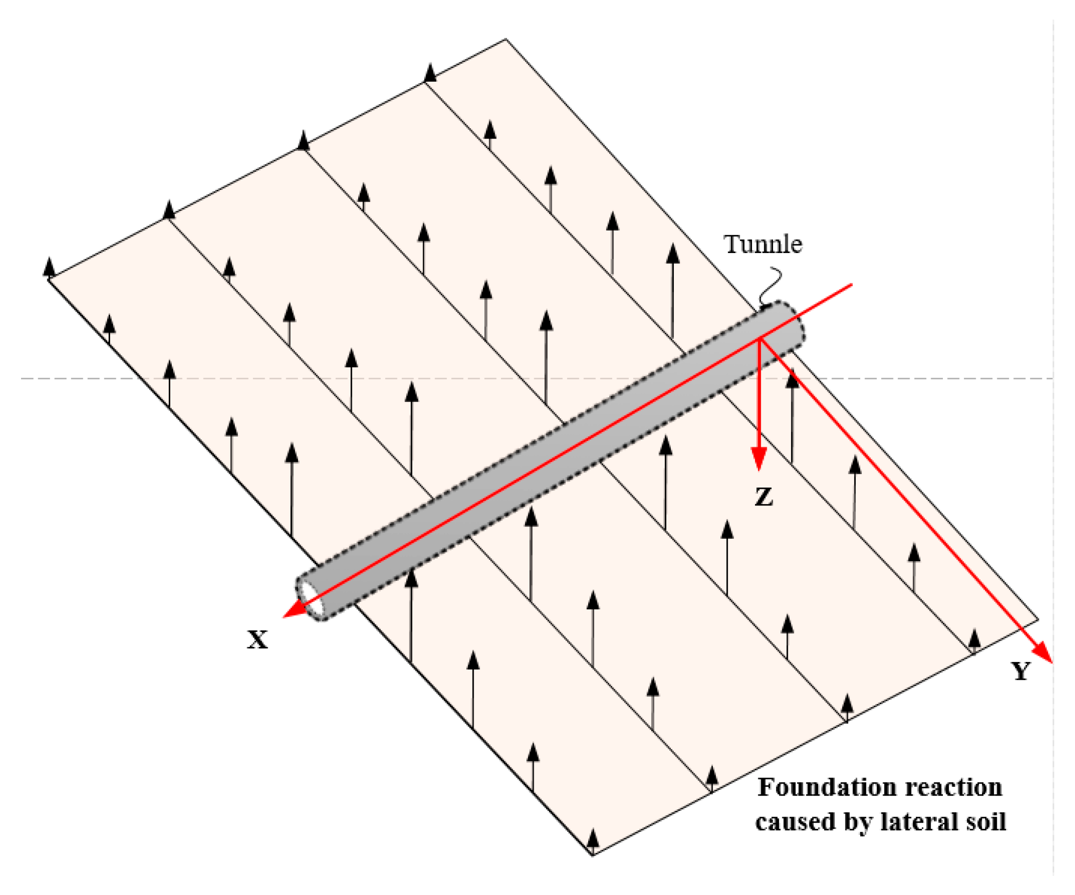
2.2. The Formulation of Equations Accounting for the Influence of Lateral Soil Action

When the tunnel experiences settlement-induced deformation due to additional loads, the soil foundation beneath the tunnel and its adjacent lateral soil exert restraining forces on the tunnel, as illustrated in Figure 1b. The deformation of the lateral soil mass in response to tunnel deformation is depicted in Figure 2, and the resultant reaction force exerted by the lateral soil mass on the tunnel is presented in Figure 3.
When analyzing the influence of lateral soil on tunnel deformation, the following assumptions are made:
(1)
The properties of the lateral soil surrounding the tunnel are consistent with those of the soil beneath the tunnel.
(2)
The restraining forces on the tunnel are T1 and T2, which are transmitted through the soil shear layer on both sides of the tunnel.
(3)
The soil used in the calculations is treated as isotropic and elastic.
(4)
The deformation of the tunnel is well-coordinated with the surrounding soil, and there is no detachment or separation between the tunnel and the soil.
For a plane defined as x = x0, the deformation equilibrium equation for the lateral soil mass surrounding the tunnel is as follows:
0 = k U ¯ ( y ) 2 t d 2 U ¯ ( y ) d y 2
where U ¯ ( y ) represents the deformation of the lateral soil shear layer along the y-axis direction of the tunnel. By solving Equation (5), the general solution can be obtained as:
U ¯ ( y ) = C 1 e k / 2 t ( y D / 2 )
As shown in Figure 2, when y = D / 2 , the lateral soil and the tunnel share the same settlement; that is, U ¯ ( x , D / 2 ) = u ( x ) . For a position that is infinitely far from the tunnel, denoted as y = Y, the corresponding settlement of the lateral soil becomes U ¯ ( Y ) = 0 . The above two equations give two boundary conditions for the model and determine the unknown coefficient C1 = u(x) in Equation (6), which thereby determines the settlement of the lateral soil as:
U ¯ ( x , y ) = u ( x ) e k / 2 t ( y D / 2 )
Furthermore, the force exerted on the tunnel by the later soil is obtained as:
T 1 ( x ) = T 2 ( x ) = 2 t d U ¯ ( x , y ) d y | y = D 2 = u ( x ) 2 t k
From above, the deformation formulation of the tunnel under the restraining effect of lateral soil is given below:
E I d 4 u ( x ) d x 4 + 2 2 t k u ( x ) = q ( x ) D

2.3. The Solution of the Tunnel Settlement Equation

In summary, considering the combined influence of the soil beneath the tunnel and the lateral soil, the settlement equation for the tunnel is as follows:
d 4 u ( x ) d x 4 γ d 2 u ( x ) d x 2 + λ 4 u ( x ) = q ( x ) D E I
where γ = 2 t D / E I and λ = ( k D + 2 2 t k ) / E I 4 . The general solution of Equation (10) can be solved by setting q ( x ) = 0 , and the result is given below:
u ( x ) = e α x [ A 1 cos ( β x ) + A 2 sin ( β x ) ] + e α x [ A 3 cos ( β x ) + A 4 sin ( β x ) ]
where A1, A2, A3 and A4 are coefficients, α = λ 2 / 2 + γ / 4 and β = λ 2 / 2 γ / 4 .
Next, we assume an infinitely long tunnel is subjected to a point load Q at x = 0. Since the length of the tunnel is assumed to be infinite, the settlement at x = ±∞ is 0, the tunnel corner at x = 0 is 0, and the shear force there is Pb/2. To determine the tunnel settlement under the concentrated load [26], the following boundary conditions are needed.
u ( ± ) = 0
d u ( x ) d x | x = 0 = 0
E p I p d 3 u ( x ) d x 3 | x = 0 = P b / 2
Taking Equations (12)–(14) back to Equation (11) gives the solution of the tunnel settlement induced by the point load as follows:
u ( x ) = Q D 4 E p I p α β ( α 2 + β 2 ) e α x ( β cos β x + α sin β x )
Assuming that the additional load caused by dewatering at a given point η on the tunnel axis is Q = q ( η ) d η , the tunnel settlement d u ( x ) induced by this load can be determined according to Equation (15) as follows:
d u ( x ) = q ( η ) D 4 E p I p α β ( α 2 + β 2 ) e α | x η | [ β cos ( β | x η | ) + α sin ( β | x η | ) ] d η
By integrating Equation (16), the tunnel settlement caused by dewatering can be obtained as:
u ( x ) = + d u ( x )
which then helps to determine the momentum as follows:
M ( x ) = E I d 2 u ( x ) d x 2

3. Loads Caused by Dewatering
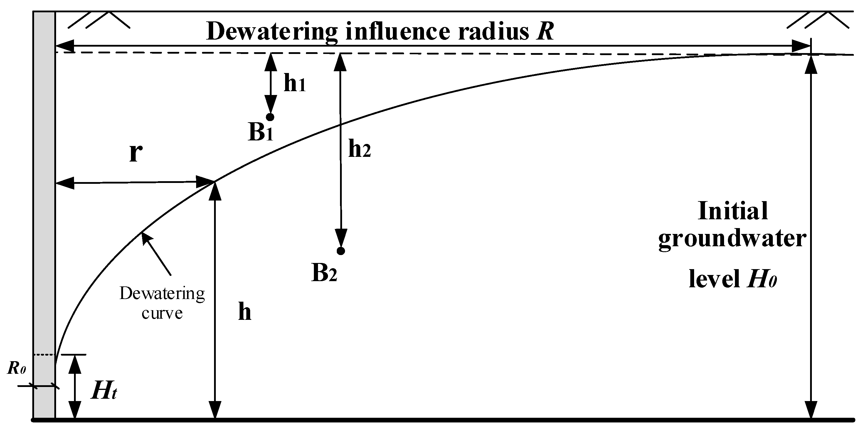
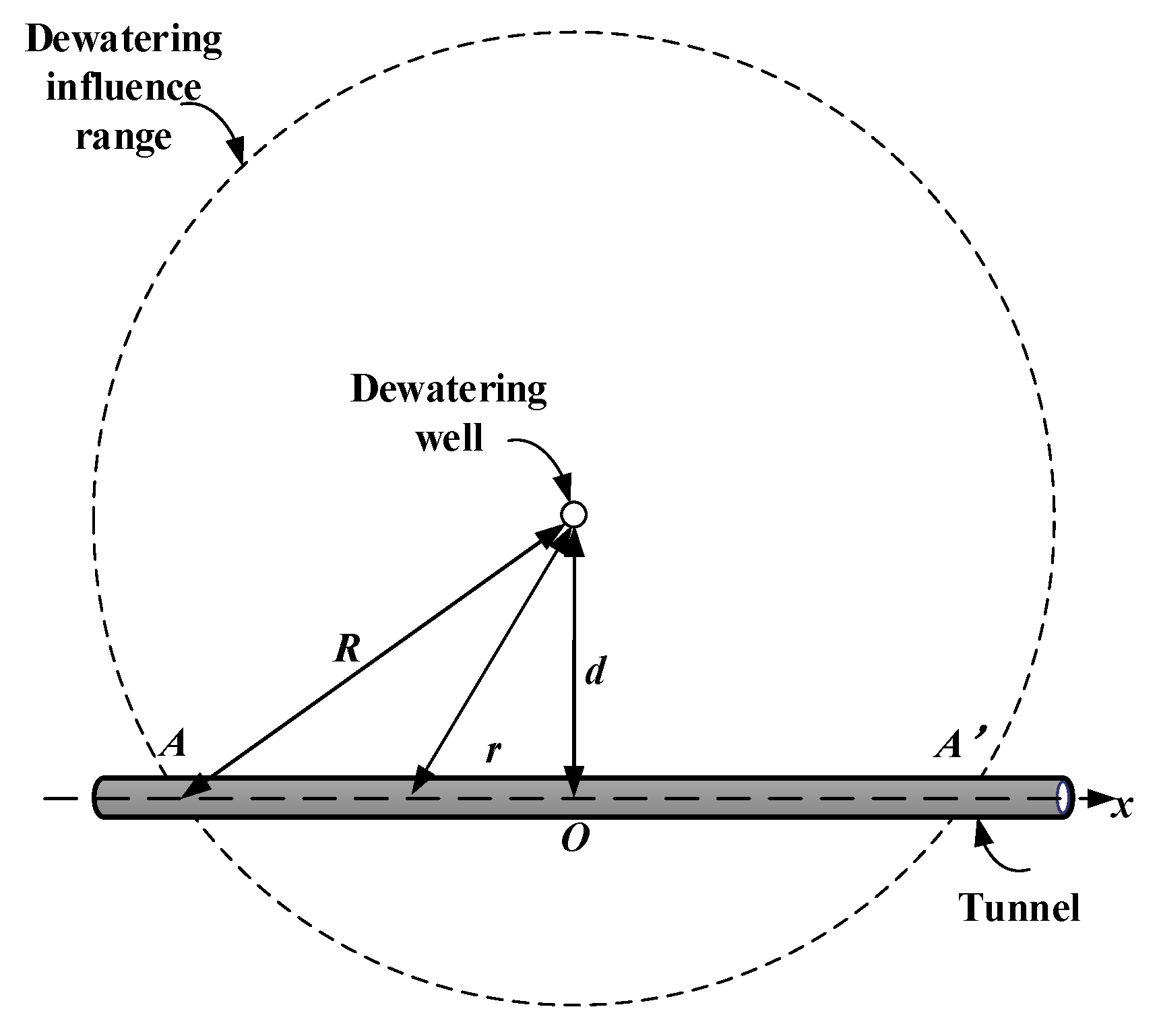
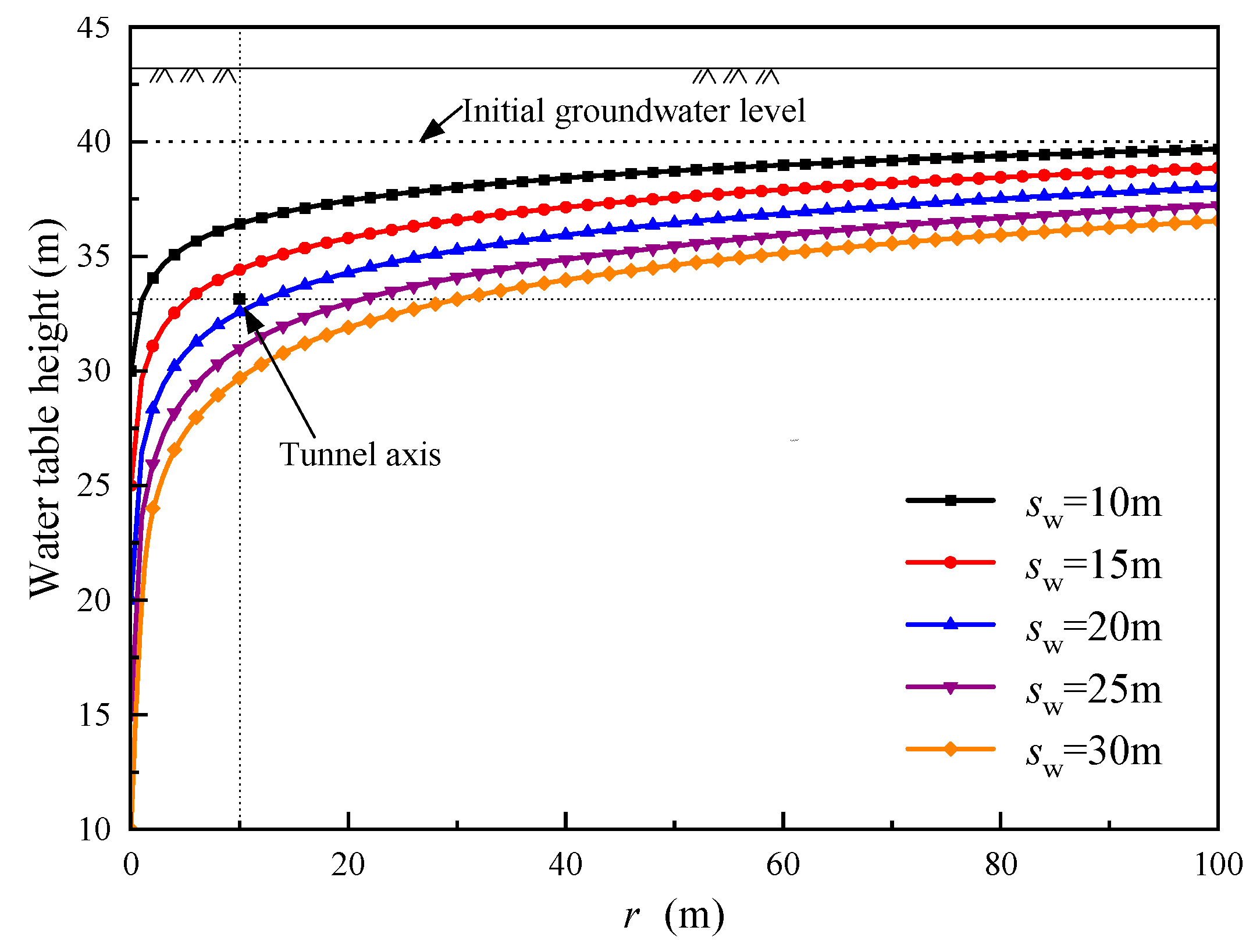
3.1. Drawdown Curve

The dewatering of a foundation pit inevitably causes changes in the surrounding groundwater level. After prolonged dewatering in an infinite confined aquifer, a stable drawdown curve of the groundwater level forms around the dewatering well [27], as shown in Figure 4. In this figure, r is the horizontal distance from a specific point to the dewatering well, h is the water level at that location, H0 is the initial water level of the confined aquifer, Ht is the water level within the well after dewatering, and R0 is the radius of the dewatering well.
Based on the Dupuit assumption, the distribution of h(r), i.e., the groundwater level around a dewatering well (the foundation pit can be considered to be a large well), is as follows [27]:
h ( r ) = H 0 2 ( H 0 2 H t 2 ) ln R r ln R R 0
where R represents the radius of the dewatering influence zone, commonly referred to as the dewatering radius. According to the Sakukin formula [27], R can be obtained as follows:
R = 2 s w k t H 0
in which kt represents the soil mass permeability coefficient, while sw signifies the height of the water level drop in the dewatering well, and it is defined as sw = H0Ht. As illustrated in Figure 5, when there is an existing tunnel within the influence zone of dewatering, the reduction in water level results in an increase in effective stress in the soil above the tunnel, thereby generating additional loads on the tunnel structure. In Figure 5, the horizontal distance between the dewatering well and the existing tunnel is denoted as d. From the nearest point on the tunnel axis towards the dewatering well, which is denoted as Point O, we established the x-axis along the tunnel’s direction. Points A and A’ are the intersections of the influence zone and the axis.

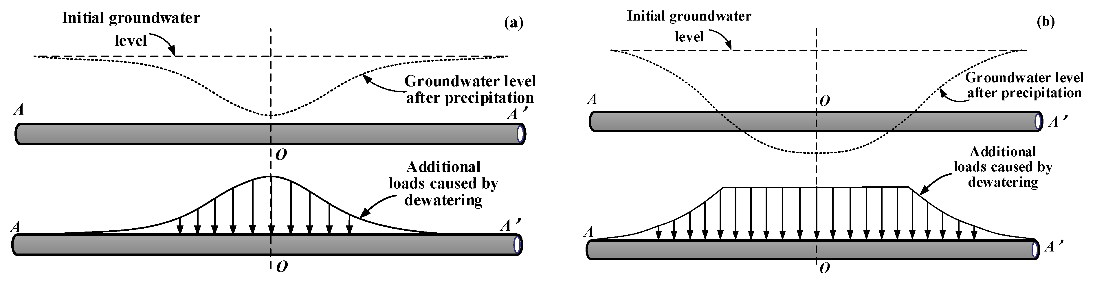
3.2. Tunnel Load Caused by Groundwater Level Drop

In an analysis of tunnel and soil-structure interaction, the weight of the soil mass above the tunnel has a significant impact [28]. The underground dewatering increases the effective stress of the soil above the tunnel, resulting in additional load on the tunnel. Depending on the relative position of the groundwater level and the calculation point, the effective stress induced by dewatering can be categorized into two distinct calculation scenarios. The increments in effective stress at points B1 and B2 in Figure 4, denoted as Δσ1 and Δσ2, respectively, are as follows:
Δ σ 1 = h 1 ( γ γ s + γ w )
Δ σ 2 = ( H 0 h ( r B 2 ) ) ( γ γ s + γ w )
In the formula, h1 represents the height difference between point B1 and the initial water level, while h(rB2) is the groundwater level at point B2. γ, γs, and γw correspond to the unit weight of soil, the saturated unit weight of soil, and the unit weight of water, respectively. Therefore, based on the relative position of the groundwater level after dewatering in relation to the existing tunnel, the additional stress on the tunnel can be categorized into the following two distinct calculation scenarios. First, following dewatering, the groundwater level is situated above the tunnel, as depicted in Figure 6a. Second, following dewatering, part of the water level drops below the tunnel, as shown in Figure 6b.
Scenario 1: The horizontal distance between point x on the tunnel and the dewatering well is given as: r = x 2 + d 2 . Taking the distance back to Equation (19) determines the groundwater level at the tunnel location after dewatering, which then can be used in Equation (21b) to obtain the additional tunnel stress as follows:
q ( x ) = ( H 0 ( H 0 2 H t 2 ) ln R x 2 + d 2 ln R R 0 ) ( γ γ s + γ w )
Scenario 2: In this scenario, the tunnel section above the water level experiences a uniform and constant additional stress, as detailed below:
σ = h 1 ( γ γ s + γ w )
The calculation of additional stress on the tunnel section below the water level can be determined using Equation (22). When h(r)= H0h1, it precisely corresponds to the point of intersection between the water level and the tunnel. Therefore, the coordinates of this specific point can be derived as follows:
x = ( R ( H 0 h 1 ) 2 H t 2 H 0 2 H t 2 R 0 ( 2 H 0 h 1 h 1 2 ) H 0 2 H t 2 ) 2 d 2
Overall, the formula for calculating the additional stress induced by foundation pit dewatering on an adjacent existing tunnel is as follows:
q ( x ) = { ( H 0 H 0 2 ( H 0 2 H t 2 ) ln R x 2 + d 2 ln R R 0 ) ( γ γ s + γ w ) , x 2 > ( R ( H 0 h 1 ) 2 H t 2 H 0 2 H t 2 R 0 ( 2 H 0 h 1 h 1 2 ) H 0 2 H t 2 ) 2 d 2 ; h 1 ( γ γ s + γ w ) , x 2 ( R ( H 0 h 1 ) 2 H t 2 H 0 2 H t 2 R 0 ( 2 H 0 h 1 h 1 2 ) H 0 2 H t 2 ) 2 d 2
So far, we obtain the additional load on the tunnel caused by the change in groundwater level. Then, the settlement and bending moment of the tunnel can be calculated by substituting Equation (22) into Equations (16)–(18).

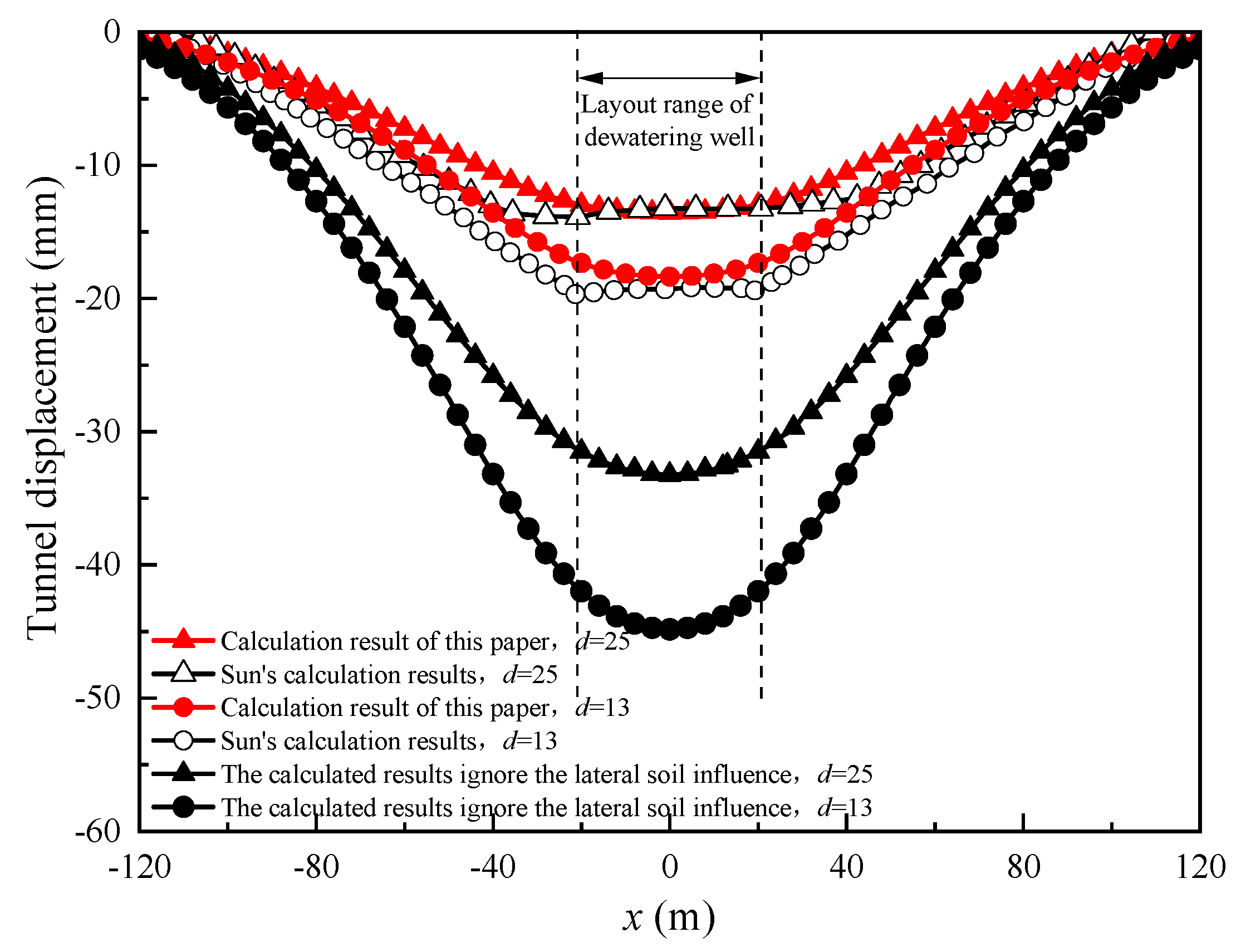
4. Validation of the Proposed Analytical Model

Sun [29] employed the ABAQUS finite element software to construct a numerical model for assessing the impact of foundation pit dewatering on pre-existing tunnels. The dimensions of the numerical model were 240 m in length, 200 m in width, and 60 m in height. The foundation pit was situated at the model center, measuring 40 m by 45 m. Dewatering wells were positioned 2 m from the outer edge of the foundation pit. The model assumed that the water level remained constant at 100 m away from the foundation pit, unaffected by dewatering. A nearby existing tunnel was characterized by a burial depth of h2 = 21 m, an outer diameter of D = 6 m, a tunnel wall thickness of 0.5 m, and an elastic modulus of E = 19 GPa. Field geological exploration and laboratory soil test results [29] indicate that the tunnel passed through a loess layer, featuring an elastic modulus of Es = 33.1 MPa, Poisson’s ratio of vs = 0.32, a soil density above the water level of 1650 kg/m3, a soil bulk density below the water level of 650 kg/m3, a soil permeability coefficient of kt = 0.8 m/d, and an initial water level burial depth of h0 = 3 m. Given that the target water level was set to be 2 m below the bottom of the foundation pit, which was 22 m in depth, the water level drop was determined as sw = 21 m.
Figure 7 illustrates a comparison of tunnel settlements, with one set calculated using the method introduced in this paper and the other neglecting lateral soil effects. The figure presents settlement curves for tunnels spaced at 13 m and 25 m from the dewatering well. It is evident that the results obtained using the method proposed in this paper closely align with those derived from the numerical model analysis. In contrast, disregarding the influence of lateral soil actions results in notable discrepancies in the calculations. This discrepancy arises because both the method outlined in this paper and the three-dimensional numerical model take into account the constraining effect of lateral soil on tunnel settlement. Neglecting this lateral soil effect is inconsistent with real-world conditions, leading to significant disparities in the calculation outcomes. By comparing our proposed method with the three-dimensional numerical model, we have substantiated the accuracy and validity of our approach.

5. Sensitivity Analysis of Parameters

To investigate the sensitivity of various parameters, we present the following engineering case study for analysis. The calculation parameters used in the case study are shown in Table 1. During the analysis of each specific parameter, all other parameters remain constant.

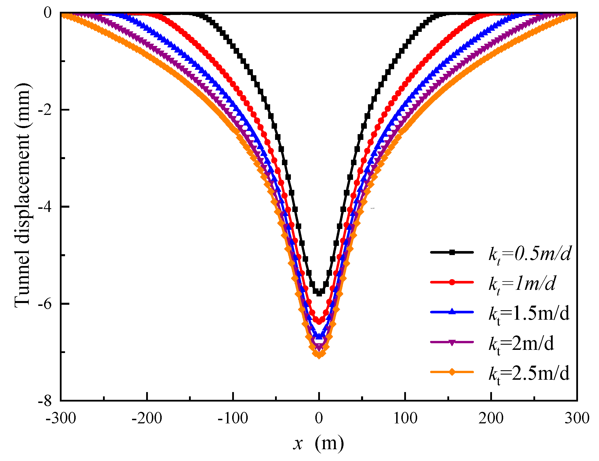
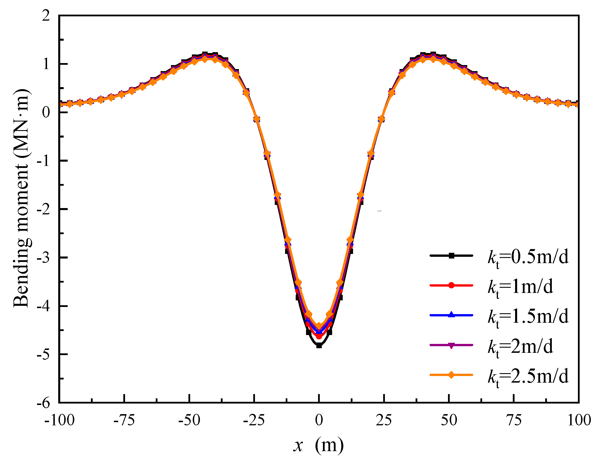
5.1. Permeability Coefficient (kt)

Five distinct permeability coefficients (kt) were examined, which were 0.5 m/d, 1 m/d, 1.5 m/d, 2 m/d, and 2.5 m/d, respectively. By utilizing the method presented in this paper, the tunnel settlement and bending moment curves resulting from foundation pit dewatering for each of these five cases were calculated, as depicted in Figure 8 and Figure 9. Figure 8 illustrates a notable trend where the vertical settlement of the tunnel and the extent of settlement increase with higher permeability coefficients. Specifically, as kt increases from 0.5 m/d to 2.5 m/d, the maximum vertical settlement of the tunnel escalates from 5.79 mm to 7.07 mm. This behavior can be attributed to the augmented permeability coefficient intensifying the scope and impact of foundation pit dewatering on the surrounding water level, consequently affecting the tunnel to a greater extent. In Figure 9, it is shown that the tunnel’s bending moment experiences a slight reduction with increasing permeability coefficients. This suggests that the permeability coefficient exerts a limited influence on the bending moment. Additionally, the region of the tunnel generating the bending moment is primarily confined within the range of x = ±100 m, which is smaller than the area responsible for the settlement.

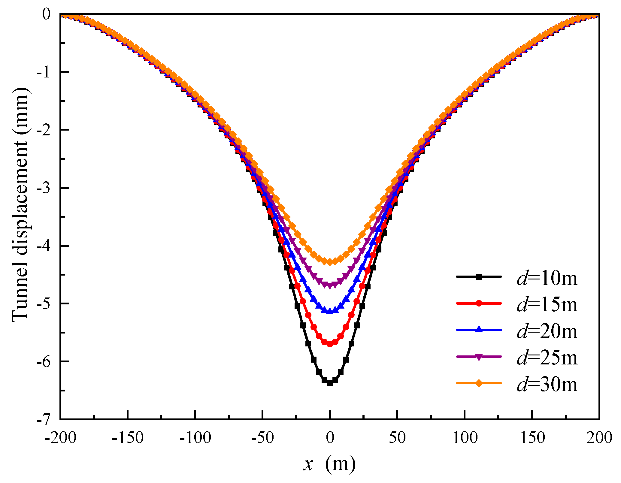
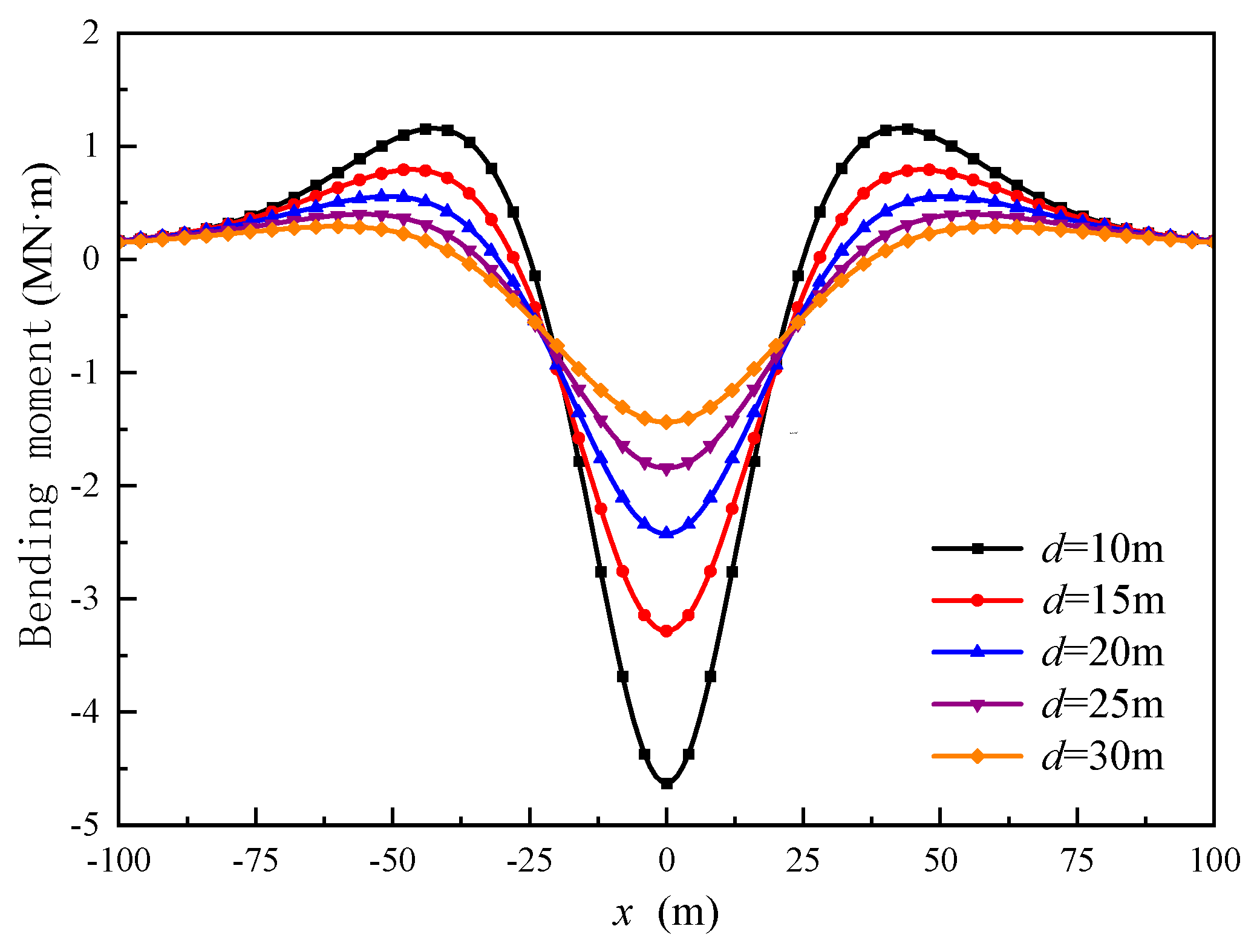
5.2. Tunnel-to-Dewatering Well Distance (d)

Five tunnel-to-dewatering well distances were used for the sensitivity analysis, which were 10 m, 15 m, 20 m, 25 m and 30 m. The resulting tunnel settlement and bending moment curves, obtained through the methodology presented in this work, are depicted in Figure 10 and Figure 11. From the observations, it is evident that an increase in the spacing leads to a reduction in both the vertical settlement and the bending moment experienced by the tunnel. Specifically, as d increases from 10 m to 30 m, the maximum vertical settlement of the tunnel decreases from 6.37 mm to 4.28 mm, and the maximum bending moment value decreases from 4.63 MN·m to 1.44 MN·m. This reduction indicates a substantial influence. The reason behind this behavior is that the water level experiences fewer fluctuations as one moves further from the dewatering well. Consequently, there is reduced stress in the proximity of the tunnel, resulting in a diminished impact on the tunnel as it is positioned farther from the dewatering well.

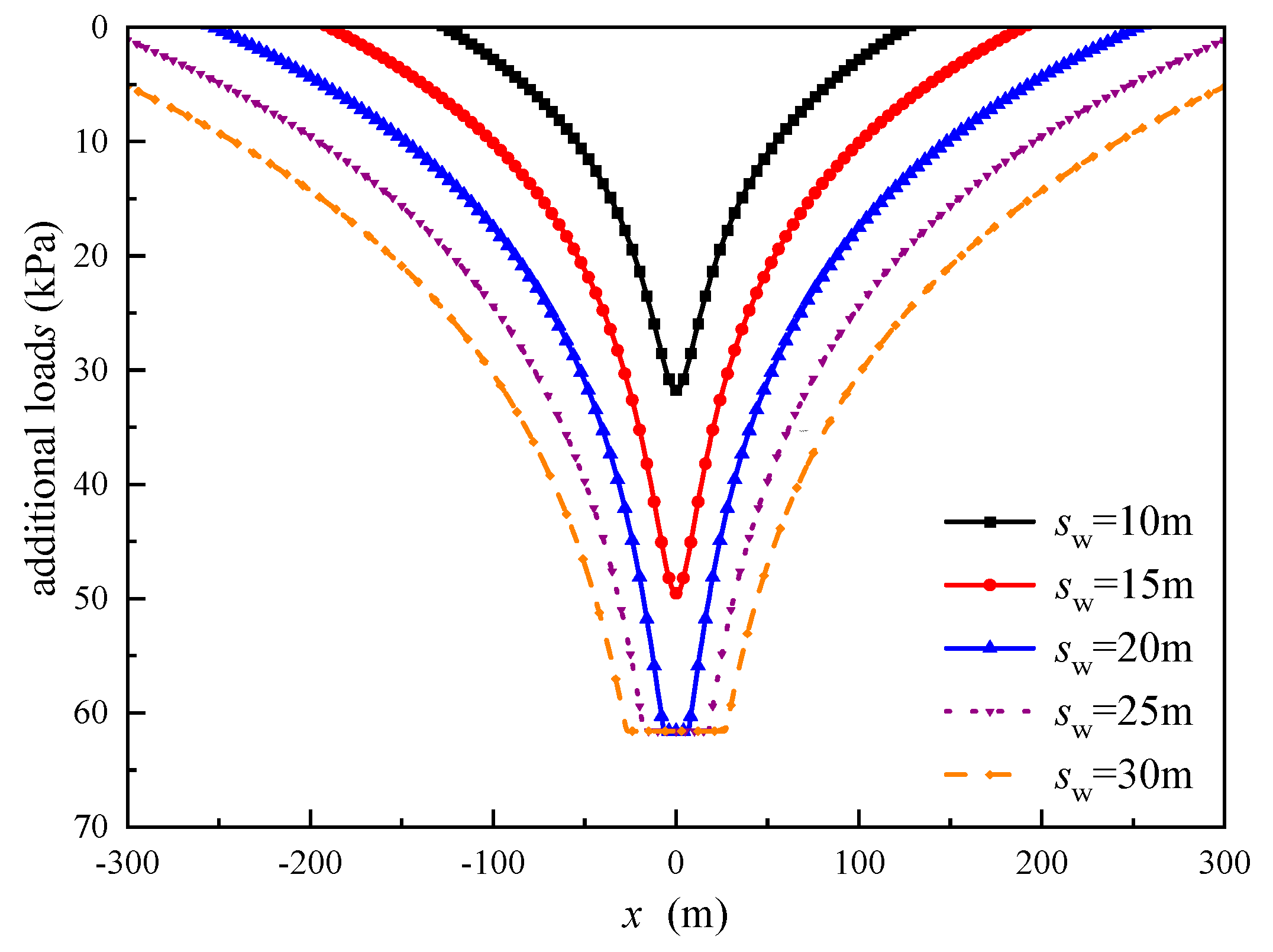
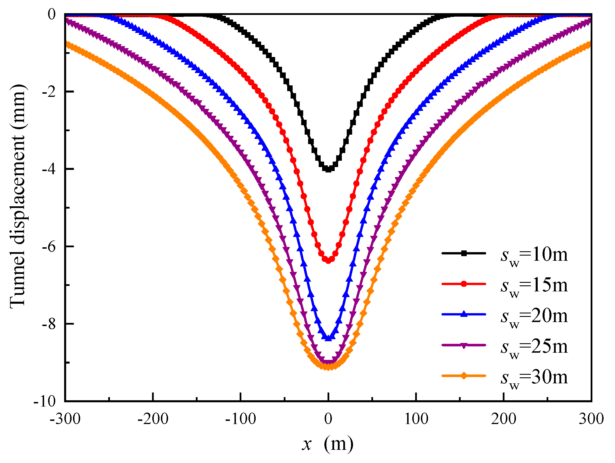
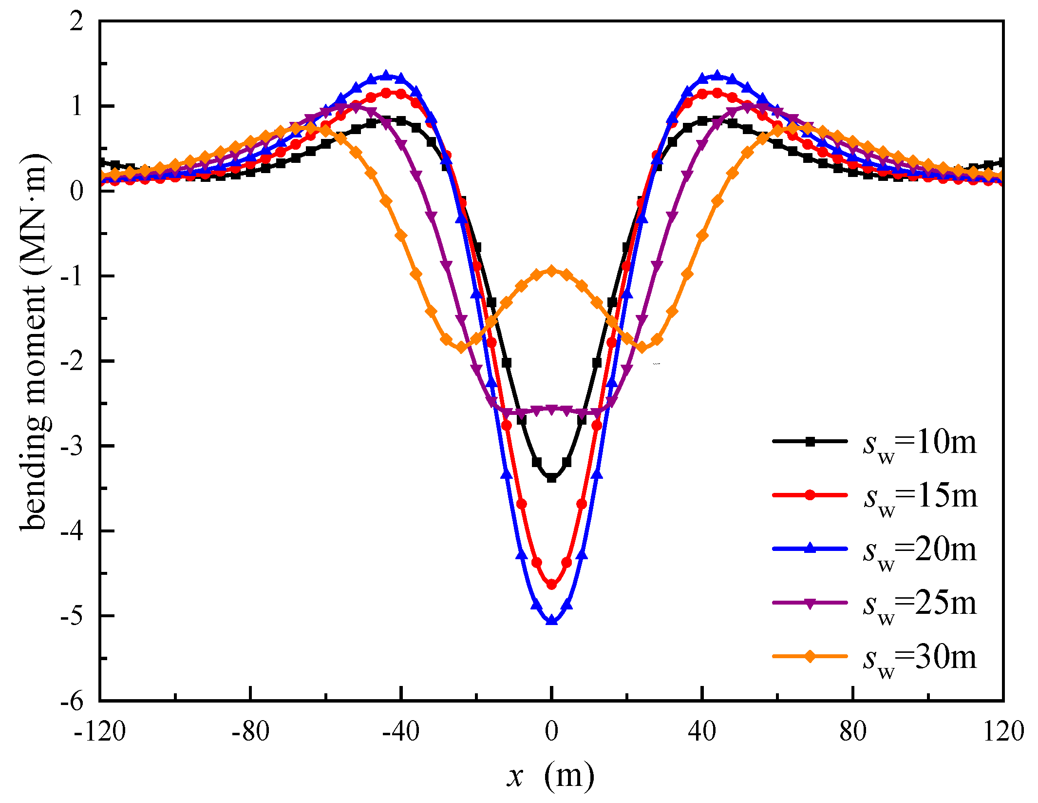
5.3. Water Level Drop (sw)

Five water level drops were studied, which were 10 m, 15 m, 20 m, 25 m and 30 m, for which the corresponding water levels in the well after dewatering were 30 m, 25 m, 20 m, 15 m and 10 m, respectively.
Figure 12 plots the underground water levels for the five scenarios. From the figure, as the sw increases, there is a corresponding decrease in the water level within the surrounding strata. When sw measures 10 m and 15 m, the burial depth of the tunnel axis remains below the groundwater level. However, as sw exceeds 20 m, the segment of the tunnel closest to the dewatering well location emerges above the water level. In Figure 13, the curves depict the additional stress levels experienced by the tunnel under various sw conditions. As shown, the additional stress on the tunnel escalates with the increase in sw. This behavior is attributed to the rise in the total effective stress within the soil above the tunnel as sw increases. Nevertheless, when the water level drops below the tunnel, the additional stress on the tunnel ceases to increase. Figure 13 also highlights that once sw within the well surpasses 20 m, the maximum value of additional stress on the tunnel remains constant, while the range over which this maximum value is generated expands.
The tunnel settlement and bending moment curves corresponding to various sw are presented in Figure 14 and Figure 15. Figure 14 reveals that as sw increases, both the vertical settlement of the tunnel and the range of settlement expand. Specifically, as sw transitions from 10 m to 30 m, the maximum vertical settlement of the tunnel rises from 4.01 mm to 9.12 mm. It is noteworthy that the rate of increase in maximum settlement significantly diminishes once sw exceeds 20 m. This can be attributed to the enhanced impact of precipitation on the surrounding water level, resulting in an increased additional load on the tunnel and, consequently, greater settlement. Figure 15 illustrates that as sw increases from 10 m to 20 m, the maximum bending moment experienced by the tunnel increases from 3.37 MN·m to 5.06 MN·m. However, with sw surpassing 20 m and reaching 30 m, the maximum bending moment starts to decline, and the position of the maximum bending moment shifts away from x = 0 to both sides. This shift results in the emergence of two symmetrical bending moment peaks. Notably, these peaks align with the region of maximum additional stress depicted in Figure 13, indicating that they coincide with the intersection between the groundwater level and the tunnel. In engineering applications, it is advisable to closely monitor the tunnel location closest to the water level during dewatering events.

6. Conclusions

This research is grounded in the Vlasov foundation model and employs theoretical methodologies to investigate the impact of foundation pit dewatering on nearby existing tunnels under the influence of lateral soil actions. The validity and precision of this approach have been confirmed through comprehensive three-dimensional finite element analysis. Furthermore, a thorough examination of the impact of various factors on tunnel deformation has been conducted through parameter sensitivity analysis. Following an extensive analysis, the following conclusions have been drawn.
(1) Considering the lateral soil constraint on tunnel deformation is more in line with actual conditions. Additionally, applying the Vlasov foundation model to simulate the interaction between the tunnel and soil can achieve more precise foundation parameters. Therefore, when predicting the settlement of an existing tunnel caused by adjacent foundation pit dewatering, the influence of the lateral soil of the tunnel should not be ignored.
(2) An increase in the permeability coefficient (kt) leads to a corresponding rise in the settlement of adjacent tunnels due to dewatering, while the bending moment experienced by the tunnel remains relatively stable. The distance (d) between the tunnel and the dewatering well exerts a notable influence on the stress deformation of the tunnel. As this distance increases, both the settlement and bending moment generated by the tunnel decrease. Therefore, in order to ensure the operational safety of the tunnel, it is preferable to position the dewatering wells at a considerable distance from the tunnel.
(3) An augmentation in the depth of the water level drop (sw) can increase additional stress and settlement on the tunnel. Nonetheless, when the water level descends beneath the tunnel axis, the maximum additional stress on the tunnel ceases to escalate but exhibits an expansion in its spatial reach. Concurrently, the maximum bending moment experienced by the tunnel initiates a decline, positioning itself at the intersection of the tunnel and the water level. Consequently, it is imperative to direct special attention to the segment of the tunnel nearest to the water level during dewatering events.
(4) This study proposes a method to predict the settlement of an existing tunnel affected by adjacent foundation pit dewatering. The method assumes elastic soil surrounding the tunnels. This assumption is reasonable when the plastic deformation of the soil is negligible. Future studies will focus on the effect of the plasticity of surrounding soils to improve the accuracy in predicting tunnel settlement.

Author Contributions

Conceptualization, X.L.; software, L.G.; validation, L.G.; investigation, X.L.; data curation, Y.T.; writing—original draft preparation, X.L.; writing—review and editing, M.C.; visualization, Y.T.; supervision, J.P.; project administration, C.X.; funding acquisition, J.P. and C.X. All authors have read and agreed to the published version of the manuscript.

Funding

This research was funded by the Key Project of National Natural Science Foundation of China, grant number 52238009, the joint fund of NSFC-Railway Corporation for basic research of high-speed railway, grant number U1934208 and Nanchang rail transit Group research project, grant number 2020HGKYB008.

Institutional Review Board Statement

Not applicable.

Informed Consent Statement

Not applicable.

Data Availability Statement

The data presented in this study are available on request from the corresponding author. The data are not publicly available due to privacy.

Conflicts of Interest

Authors Xinhua Liang, Min Chen, and Junren Peng were employed by the company Nanchang Rail Transit Group Limited Corporation. The remaining authors declare that the research was conducted in the absence of any commercial or financial relationships that could be construed as a potential conflict of interest.

References

  1. Zeng, C.F.; Zheng, G.; Zhou, X.F.; Xue, X.L.; Zhou, H.Z. Behaviours of wall and soil during pre-excavation dewatering under different foundation pit widths. Comput. Geotech. 2019, 115, 103169.1–103169.13. [Google Scholar] [CrossRef]
  2. Ye, X.W.; Ran, L.; Yi, T.H.; Dong, X.B. Intelligent Risk Assessment for Dewatering of Metro-Tunnel Deep Excavations. Math. Probl. Eng. 2012, 2021 Pt 12, 60–66. [Google Scholar] [CrossRef]
  3. Shi, J.; Wu, B.; Liu, Y.; Xu, S.; Hou, J.; Wang, Y.; Sun, Q.; Meng, G.; Nong, Z.; Qiu, H.; et al. Analysis of the influence of groundwater seepage on the deformation of deep foundation pit with suspended impervious curtain. Adv. Mech. Eng. 2022, 14, 117–121. [Google Scholar] [CrossRef]
  4. Zhang, X.; Wang, L.; Wang, H.; Feng, C.; Shi, H.; Wu, S. Investigating impacts of deep foundation pit dewatering on land subsidence based on CFD-DEM method. Eur. J. Environ. Civ. Eng. 2022, 26, 6424–6443. [Google Scholar] [CrossRef]
  5. Zeng, C.; Ning, B.A.I.; Yuan, Z.; Xue, X.; Mei, G. Effect of buried depth of adjacent structure on the foundation pit deformation during pre-excavation dewatering. J. China Univ. Min. Technol. 2022, 51, 283–292. (In Chinese) [Google Scholar]
  6. Guo, H.; Ma, D.; Yao, A. Deformation Responses and Mechanical Mechanism of Existing Tunnel due to New Building Construction. Adv. Civ. Eng. 2021, 3, 6623234. [Google Scholar] [CrossRef]
  7. Liu, W.; Zhu, J.; Zhang, H.; Ma, X.; Xie, J. Geological conditions of saturated soft loess stratum and influence of tunnel excavation and dewatering system on its groundwater environment. Bull. Eng. Geol. Environ. 2022, 81, 128. [Google Scholar] [CrossRef]
  8. Dai, L.; Pan, Y.; Li, Z.; Wang, A.; Xiao, Y.; Liu, F.; Shi, T.; Zheng, W. Quantitative mechanism of roadway rockbursts in deep extra-thick coal seams: Theory and case histories. Tunn. Undergr. Space Technol. 2021, 111, 103861. [Google Scholar] [CrossRef]
  9. Guo, P.; Liu, F.; Lei, G.; Li, X.; Zhu, C.W.; Wang, Y.; Lu, M.; Cheng, K.; Gong, X. Predicting Response of Constructed Tunnel to Adjacent Excavation with Dewatering. Geofluids 2021, 2021, 5548817. [Google Scholar] [CrossRef]
  10. Zheng, G.; Deng, X.; Liu, Q. Analysis of responses of existing shield tunnel to pressure-relief in confined aquifer. Rock Soil Mech. 2015, 36, 178–188. (In Chinese) [Google Scholar]
  11. Wang, J.; Wang, P.; Wang, W.; Zhou, S.; Fang, X. Optimization Analysis of Deformation of Underlying Tunnel in Dewatering and Excavation of Phreatic Aquifer. Adv. Mater. Sci. Eng. 2019, 2019, 2461817. [Google Scholar] [CrossRef]
  12. Wang, L.; Ou, R.; Zheng, G. Effect of jet grouting and dewatering on adjacent tunnel in a Shanghai deep excavation. Proc. Inst. Civ. Eng. Ground Improv. 2019, 172, 274–284. [Google Scholar] [CrossRef]
  13. Song, J.X.; Nie, X.H.; Zhang, J.Y. Prediction technology of adjacent underground pipelines damage caused by excavations dewatering. Build. Sci. 2014, 15, 74–79. (In Chinese) [Google Scholar]
  14. Li, H. The Analysis of Influence of extra-deep Foundation Pit Dewatering and Excavation on the Adjacent Tunnels. Master’s Thesis, Southeast University, Nanjing, China, 2019. (In Chinese). [Google Scholar]
  15. Sun, Y.; Rong, Y.; Yu, J.; Zhu, L.; Ding, H.; Tong, L. Theoretical study on longitudinal deformation of adjacent tunnel subjected to pre-dewatering based on Pasternak-Timoshenko beam model. Front. Earth Sci. 2023, 10, 1114987. [Google Scholar]
  16. Xu, C.; Zeng, Y.; Tian, W.; Chen, M. Analytical analysis of the influence on adjacent pipelines induced by dewatering based on Pasternak model. J. Shanghai Jiaotong Univ. 2021, 55, 11. (In Chinese) [Google Scholar]
  17. Zhang, X.; Ou, X.; Yang, J.; Fu, J. Deformation response of an existing tunnel to upper excavation of foundation pit and associated dewatering. Int. J. Geomech. 2017, 17, 0000814. [Google Scholar] [CrossRef]
  18. Huang, M.; Zhou, X.; Yu, J.; Leung, C.F.; Tan, J.Q.W. Estimating the effects of tunnelling on existing jointed pipelines based on Winkler model. Tunn. Undergr. Space Technol. 2019, 86, 89–99. [Google Scholar] [CrossRef]
  19. Liang, R.; Xia, T.; Huang, M.; Lin, C. Simplified analytical method for evaluating the effects of adjacent excavation on shield tunnel considering the shearing effect. Comput. Geotech. 2017, 81, 167–187. [Google Scholar] [CrossRef]
  20. Yin, Z.-Y.; Wang, P.; Zhang, F. Effect of particle shape on the progressive failure of shield tunnel face in granular soils by coupled FDM-DEM method. Tunn. Undergr. Space Technol. 2020, 100, 103394. [Google Scholar] [CrossRef]
  21. Huang, Z.-K.; Li, Z.-L.; Zong, X.; Zhang, D.-M. Analytical solution for the response of an existing tunnel to a new tunnel excavation underneath. Comput. Geotech. 2019, 108, 197–211. [Google Scholar]
  22. Vlasov, V.Z.; Leont’ev, N.N. Beams, Plates and Shells on Elastic Foundations; Israel Program for Scientific Translations: Jerusalem, Israel, 1966. [Google Scholar]
  23. Guan, L.; Wang, P.; Ding, H.; Qin, J.; Xu, C.; Feng, G. Forthcoming. Analysis of Settlement of an Existing Tunnel Subjected to Undercrossing Tunneling Based on the Modified Vlasov Model. Int. J. Geomech. 2023; in press. [Google Scholar]
  24. Zhang, H.; Zhang, Z. Vertical Deflection of Existing Pipeline Due to Shield Tunnelling. J. Tongji Univ. Nat. Sci. Ed. 2013, 41, 1172–1178. (In Chinese) [Google Scholar]
  25. Jia, H.; Wang, N.; Ding, H.; Guan, L. Impact of Tunneling on Adjacent Piles Based on the Kerr Foundation Model Considering the Influence of Lateral Soil. Buildings 2023, 13, 2548. [Google Scholar] [CrossRef]
  26. Ke, W.H.; Guan, L.X.; Liu, D.H. Study on the Soil-Pipeline Interaction Induced by Tunneling. Rock Soil Mech. 2020, 41, 221–228+234. (In Chinese) [Google Scholar]
  27. Verruijt, A. Theory of Groundwater Flow; Macmillan Education: London, UK, 1982. [Google Scholar]
  28. Lakirouhani, A.; Jafari, R.; Hasanzadehshooiili, H. Three-Dimensional Finite Difference Analysis on the Ground-Sequential Tunneling-Superstructure Interaction. Adv. Civ. Eng. 2021, 2021, 9464225. [Google Scholar] [CrossRef]
  29. Sun, D. The Study of the Influence of a Building Foundation Pit Dewatering on the Stability of the Surrounding Metro Tunnel. Master’s Thesis, Xi’an University of Technology, Xi’an, China, 2016. (In Chinese). [Google Scholar]
Figure 1. Vlasov foundation beam model diagram: (a) front view; (b) side view.
Applsci 14 00102 g001
Figure 2. Schematic diagram of lateral soil deformation.
Applsci 14 00102 g002
Figure 3. Diagram of restraining force exerted by the lateral soil on tunnel.
Applsci 14 00102 g003
Figure 4. The dewatering curve diagram.
Applsci 14 00102 g004
Figure 5. The scope of influence of dewatering.
Applsci 14 00102 g005
Figure 6. The distribution of water levels and additional loads along the tunnel after dewatering: (a) the water level remains higher than the tunnel after dewatering; (b) part of the water level drops below the tunnel after dewatering.
Applsci 14 00102 g006
Figure 7. Tunnel settlement comparison between results from the proposed model, the method ignoring the lateral influence and 3D simulations.
Applsci 14 00102 g007
Figure 8. Curves of tunnel displacement under different permeability coefficients of soil kt.
Applsci 14 00102 g008
Figure 9. Curves of the tunnel’s bending moments under different permeability coefficients of soil kt.
Applsci 14 00102 g009
Figure 10. Curves of tunnel displacement under different spacing d.
Applsci 14 00102 g010
Figure 11. Curves of the tunnel’s bending moments under different spacing d.
Applsci 14 00102 g011
Figure 12. Curves of water level under different water level drop depths sw.
Applsci 14 00102 g012
Figure 13. Curves of additional stress under different water level drop depths sw.
Applsci 14 00102 g013
Figure 14. Curves of tunnel displacement under different water level drop depths sw.
Applsci 14 00102 g014
Figure 15. Curves of tunnel bending moments under different water level drop depths sw.
Applsci 14 00102 g015
Table 1. Calculation parameters of this paper.
Groundwater PropertiesSoil PropertiesTunnel Properties
PropertiesValuePropertiesValuePropertiesValue
Initial groundwater level (H0)40 mPermeability coefficient (kt)1 m/dayDistance between the tunnel and the dewatering well (d)12 m
Initial water level burial depth (h0)3 mElastic modulus (Es)30 MPaBurial depth (z)10 m
Water level in the well after dewatering (Ht)25 mPoisson’s ratio (v)0.3Burial depth of the tunnel roof (h2)9 m
Water level drop (sw)15 mSoil mass density (γ)18 kN/m3Tunnel diameter (D)6 m
Saturated unit weight (γs)19 kN/m3Wall thickness0.3 m
Bending stiffness (EI)7.548 × 10⁵ MN·m2
Disclaimer/Publisher’s Note: The statements, opinions and data contained in all publications are solely those of the individual author(s) and contributor(s) and not of MDPI and/or the editor(s). MDPI and/or the editor(s) disclaim responsibility for any injury to people or property resulting from any ideas, methods, instructions or products referred to in the content.

