Communication

Infrared All-Dielectric Metasurface Beam Splitter Based on Transflective Structures

1
Changchun Institute of Optics, Fine Mechanics and Physics, Chinese Academy of Sciences, Changchun 130033, China
2
University of Chinese Academy of Sciences, Beijing 101408, China
3
Center for Advanced Optoelectronic Functional Materials Research and Key Laboratory of UV Light-Emitting Materials and Technology of Ministry of Education, College of Physics, Northeast Normal University, Changchun 130024, China
*
Author to whom correspondence should be addressed.
Appl. Sci. 2023, 13(8), 5207; https://doi.org/10.3390/app13085207
Submission received: 21 March 2023 / Revised: 17 April 2023 / Accepted: 20 April 2023 / Published: 21 April 2023
(This article belongs to the Special Issue Design and Applications of Plasmon-Based Nanodevices)

Abstract

:
Beam splitters are widely applied in various optical systems as a common beam-splitting device. The conventional stereoscopic and flat-type beam splitters greatly limit the packaging and integration of optical systems due to their large size and restricted emitting direction. Recently, beam-splitting devices made of various transmissive or reflective metasurfaces have shown the potential to overcome these challenges. However, in optical systems such as machine vision, these single-ended beam splitters increase the design complexity of the signal feedback link due to the limitation of the beam-splitting path direction. Here, we proposed and numerically simulated a transflective all-dielectric metasurface beam splitter by applying incompletely transmissive structural designs to the metasurface and using the transmission phase modulation mechanism. It can realize the beam separation for arbitrarily polarized incident light on the same side of the normal at both transmissive and reflective ends with a single-layer unit cell arrangement structure and has a similar emergence angle. The results reveal that at 1550 nm, the angular tolerance bandwidth is about 32°, the total splitting efficiency is over 90%, and the splitting ratio is approximately 1:1. After comparison and verification of simulation results, this transflective metasurface beam splitter is hopeful to be applied in new compact optical systems that require real-time signal feedback, such as coaxial light sources and photoelectric sensing.

1. Introduction

In recent years, with the continuous improvement of the process manufacturing level, the size of silicon optical waveguides on an insulator base gradually decreased, and the photonic integrated system has been widely used in fiber optic communication, optical computing, photoelectric detection, and other fields [1,2,3]. It could achieve more functions with a smaller size, but that would also require its components to be miniaturized and multifunctionalized. A beam splitter (BS), which could distribute the optical beam paths, performs as one of the most fundamental function blocks in lots of optical systems, such as interferometers [4], optical communications [5], and optical detection [6]. Beam splitters can usually be divided into polarization beam splitters (PBS) [7,8,9,10,11] and non-polarization beam splitters (NPBS) [8,9,10,11,12,13,14,15] by polarization. They have been intensively investigated in both space and on-chip optical systems. Due to its dependence on the crystal birefringence effect and the optical path accumulation effect, the conventional cube BS is hard to integrate into compact optical systems. Furthermore, as more compact alternatives, some flat-type BSs [16,17,18] have been recently demonstrated. Although these BSs have significantly smaller sizes than cube BSs, they are still unsuitable for integration because of their sensitivity to the incident angle, fixed emergence angle, and other problems.
Metasurfaces are artificial, sub-wavelength, two-dimensional, planar structural materials. Due to their significant advantages in compactness, easy integration, and capacity to arbitrarily modulate electromagnetic waves, which have been extensively employed in various research fields, including spectrum imaging, neural networks, thermal radiation cladding, absorbing material, and so on [19,20,21,22,23,24,25,26,27,28,29,30,31]. In general, metasurfaces can be classified into metallic metasurfaces and dielectric metasurfaces according to their constituent materials. Both kinds of metasurfaces have made considerable contributions to beam-dividing devices. Not only have many advances been made in PBSs [32,33,34,35], but Chen et al. recently also used a symmetric Si nanoring structure to construct a near-infrared band splitter ratio tunable (0.5:1~1:1) all-dielectric metasurface BS [36]; Tian et al. demonstrated a free-space optical multiport amorphous Si metasurface beam splitter with an arbitrarily predetermined output port number (2~7) by a gradient-descent-based iterative algorithm [37]. Compared to metallic metasurfaces, dielectric metasurfaces have easily tunable scattering and high transmission efficiency while having almost no absorption loss. They make dielectric metasurfaces an excellent choice for BS designs. Currently, metasurface BSs are usually designed to act only on transmitted or reflected light, which makes it necessary to attach additional light path conversion devices when the light path back from the splitting beam is used as a feedback signal, hindering further integration of optical systems.
In this context, we propose a transflective all-dielectric metasurface beam splitter based on a single-layer, incompletely transmissive Si nanocolumn structure. It could achieve a beam-splitting function by sequentially arranging nanocolumns of different radii for arbitrary polarization lights with a splitting ratio of 59%:41%, a total splitting efficiency (TES) of 93.3%, and an angular bandwidth of about 32°. In this work, the light transmitted through the metasurface and reflected from the nanocolumns and substrate intersections both pass through the unit cell once, and then the transmitted and reflected lights are subjected to an isophase modulation. Therefore, it shows a phenomenon in which the transmitted and reflected light are separated on the same side of the normal at a similar emergence angle. This transflective metasurface BS can obtain a feedback signal while splitting the beam to correct the operating parameters of the optical system, which is hopeful to be used in the design of feedback links for optical detection, interferometers, and other integrated optical systems.

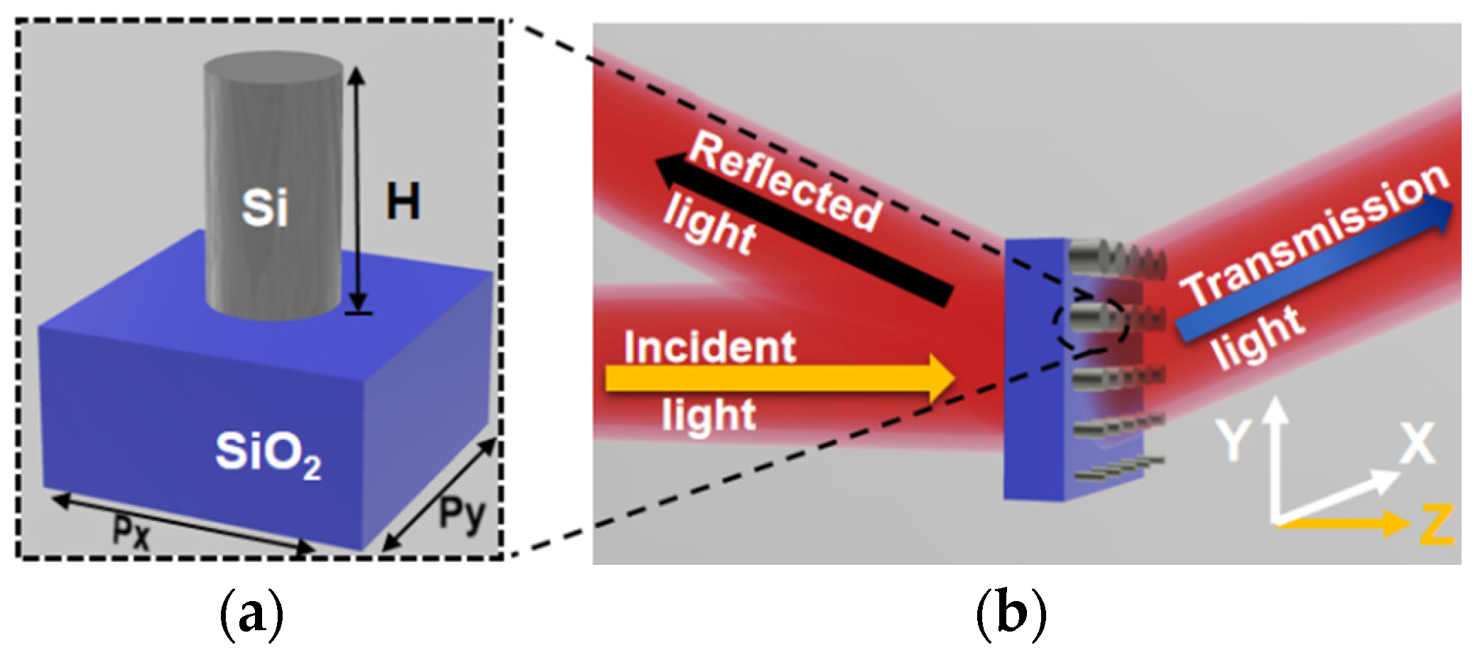
2. Structural Design and Simulation
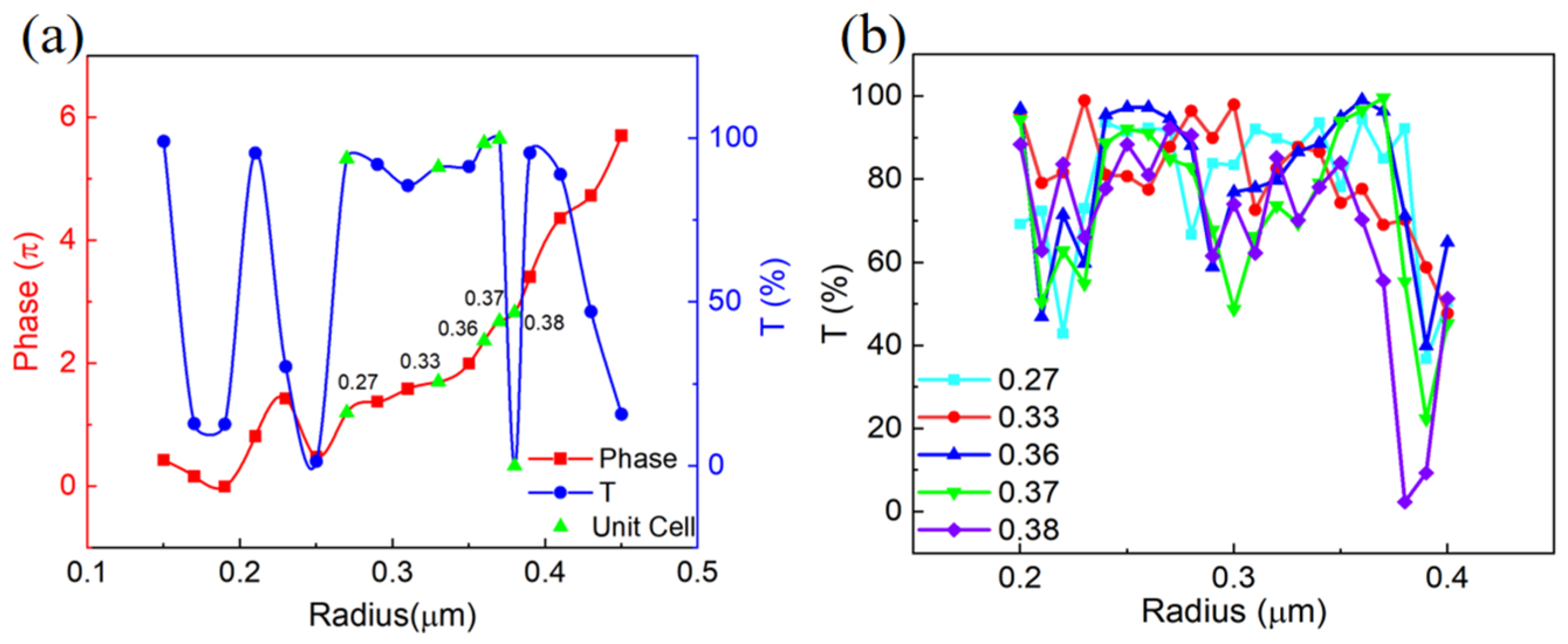
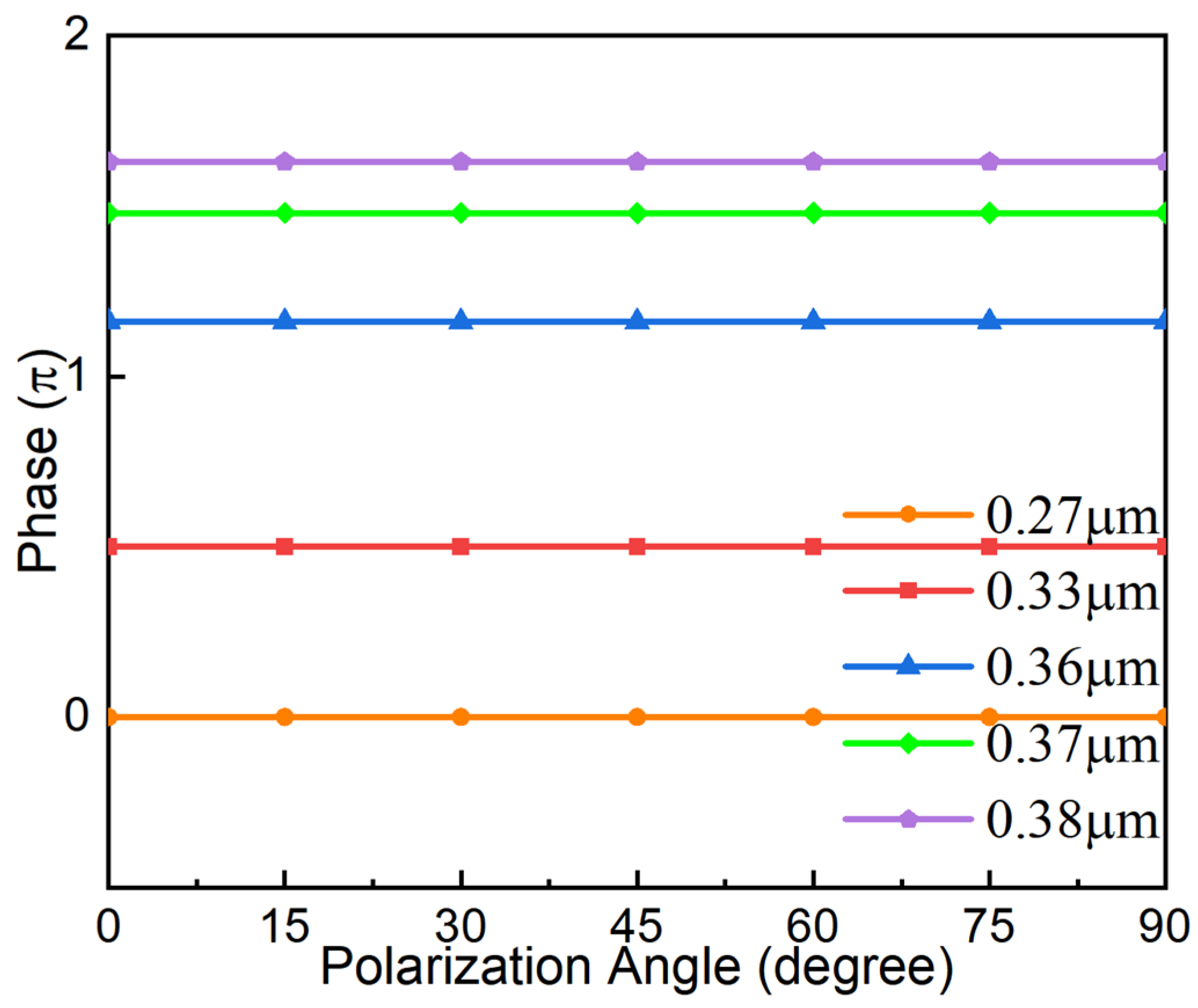
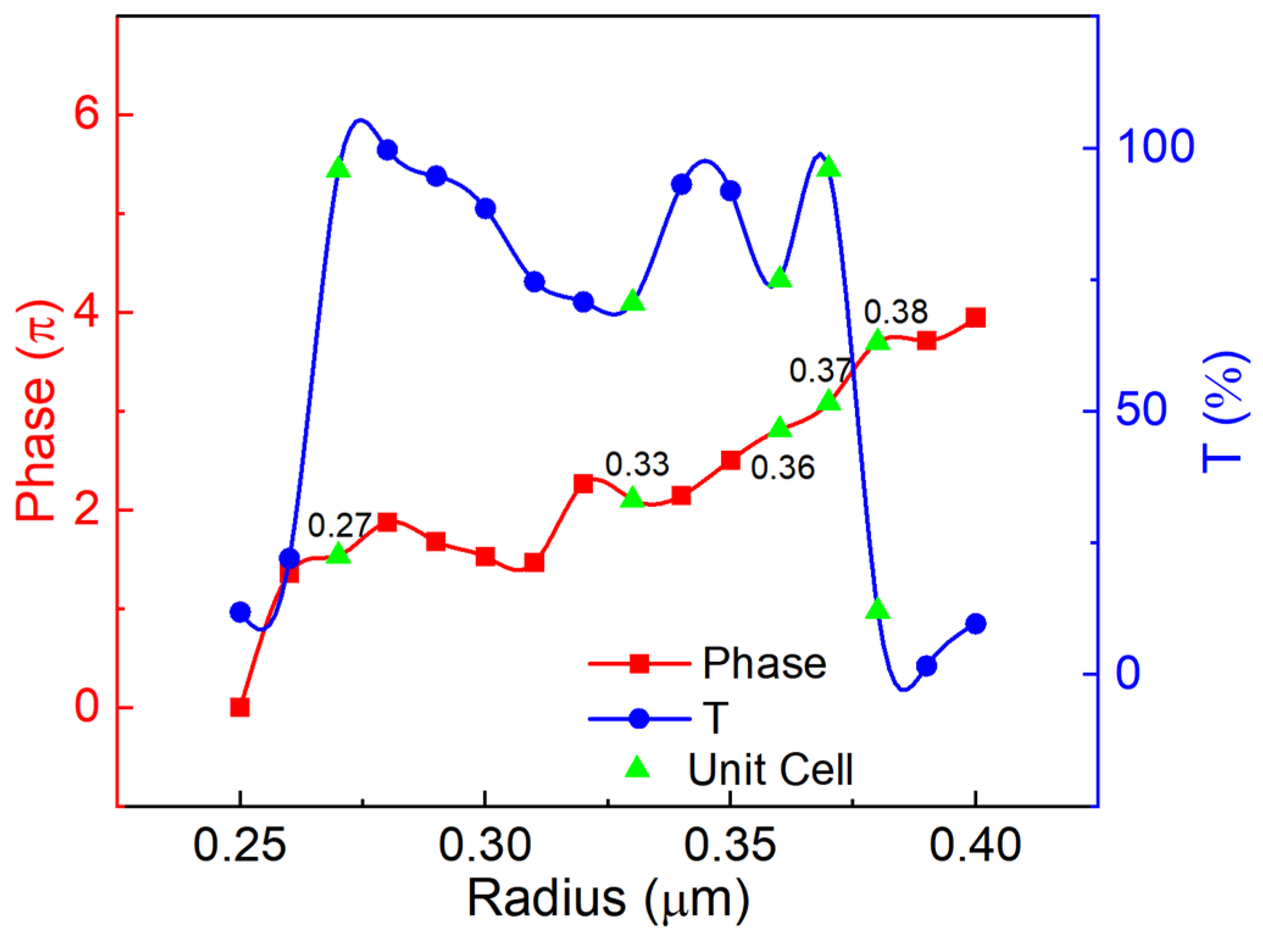
The basic working principle of metasurfaces is to introduce phase discontinuity along the interface by designing the geometry shape of unit cells and arranging them according to certain rules, which can control the wavefronts of the reflected or transmitted beams. When the incident light field transmits through the metasurface, it will inspire the Mie resonance of the all-dielectric unit cell, which will greatly change the effective refractive index of the unit and lead to a certain phase delay. The process can be described by the truncated waveguide effect of the unit cell [38,39]:
ϕ t p = k 0 n e f f H
where ϕ t p is the phase shift introduced by the transmission phase; k 0 is the wave vector; n e f f is the effective refractive index of the metasurface unit waveguide; and H   is the metasurface unit height. According to generalized Snell’s law, the departure angles of outgoing beams at two ends can be expressed by the following equation [40]:
n t sin ( θ 1 ) = n r sin ( θ 2 ) = n i sin ( θ i ) + λ 0 2 π d ϕ t p d x
where θ i is the incident angle; n t , n r , and n i are the refractive indices of the transmissive, reflective, and incident media, respectively; and d ϕ t p is the phase change. When the beam is normal incident on the metasurface in air, and due to the transflective structure of the metasurface, the θ i = 0, n t = n r and Equations (1) and (2) can be written as:
sin ( θ 1 ) = sin ( θ 2 ) = τ n t P λ 0 2 π
where τ = P × d ϕ t p d x is the phase interval and P is the spacing period. The splitting ratio of the metasurface BS can be defined as:
S R = T R
Here T and R represent the transmittance and reflectivity of the transflective metasurface BS.
Based on the above theory, each unit cell on the metasurface is built as a circular Si nanocolumn on a SiO2 (n = 1.44) substrate with a thickness of 6 μm. Si was chosen as the nanocolumn material because of its high refractive index (~3.48) and low absorption coefficient (4.44 × 10⁻¹⁶) at the 1.55 μm wavelength, which give a substantial refractive index contrast with the background and hence improve the ability of phase modulation [41]. The period P of the unit cells is set to 1 μ m, the height H of the nanocolumn is set to 3.2 μm, and the final metasurface beam splitter beam-splitting schematic is illustrated in Figure 1a,b.
We chose to vary the equivalent refractive index by changing the radius of the nanocolumn to accomplish the needed phase slope design for deflected beam splitting since the height of the unit cell is constant. Figure 2a depicts the variation of phase and transmittance with the radius of the nanocolumn. Due to the relatively stable variation of phase and transmittance, the range from 0.25 μm to 0.4 μm is selected as the radius variation range of the nanocolumn. Since the Fabry–Perot resonance generated by the unit cells at a specific radius will cause the interference extinction phenomenon of the outgoing light, it can cause significant transmittance troughs, and since the nanocolumns have the same period but different radii, the transmittance of two adjacent nanocolumns also changes with the distance as shown in Figure 2b. They both help to reduce the overall transmittance of the metasurface. The main approach to achieving a transflective metasurface is to reduce the overall transmittance of the metasurface without significantly impacting its performance, which is achieved by selecting a small number of specific low transmittance unit cell size structures and controlling the distance between unit cells. In this paper, we set the phase spacing between adjacent nanocolumns along the y-axis to π / 2 to construct an equal phase plane with a certain slope to make the incident light positively deflected along the y-axis. According to Figure 2, we select four values with a relatively stable change in transmittance and a phase interval of π / 2 between them as the radii of the units, and one low transmittance unit cell radius size to reduce the overall transmittance of the metasurface. The metasurface beam splitter after arranging unit cells from small to large radii is shown in Figure 1b, with radii of 0.27 μm, 0.33 μm, 0.36 μm, 0.37 μm, and 0.38 μm. Furthermore, the transmittance and additional phase for the various radii are shown in Table 1.
Figure 1. (a) The columnar unit cells of the parallel light-splitting metasurface beam splitter. The materials of the nanocolumn and the substrate are Si and SiO2, the geometric parameters of the cell are period Px = Py = P = 1 μm, and the height of the nanocolumn is H = 3.2 μm. (b) The schematic of the parallel light-splitting metasurface beam splitter, with blue arrows for transmitted light, black for reflected light, and yellow for incoming light.
Applsci 13 05207 g001
The design was numerically simulated by the Finite Difference in Time Domain (FDTD) technique method. The light source is a 1.55 μm linearly polarized plane wave incident on the metasurface along the positive z-axis. The reflected and transmitted light phase conditions, incidence angle tolerance, and light field intensity distribution were recorded and evaluated in the incident light direction (reflective end) and the transmitted light direction (transmissive end) in the Y–Z plane, respectively.
Table 1. The transmittance and additional phase for the various radii.
Radius (μm)0.270.330.360.370.38
Phase0 0.50 π 1.16 π 1.48 π 1.63 π
T(%)93.7491.1294.9799.750.18

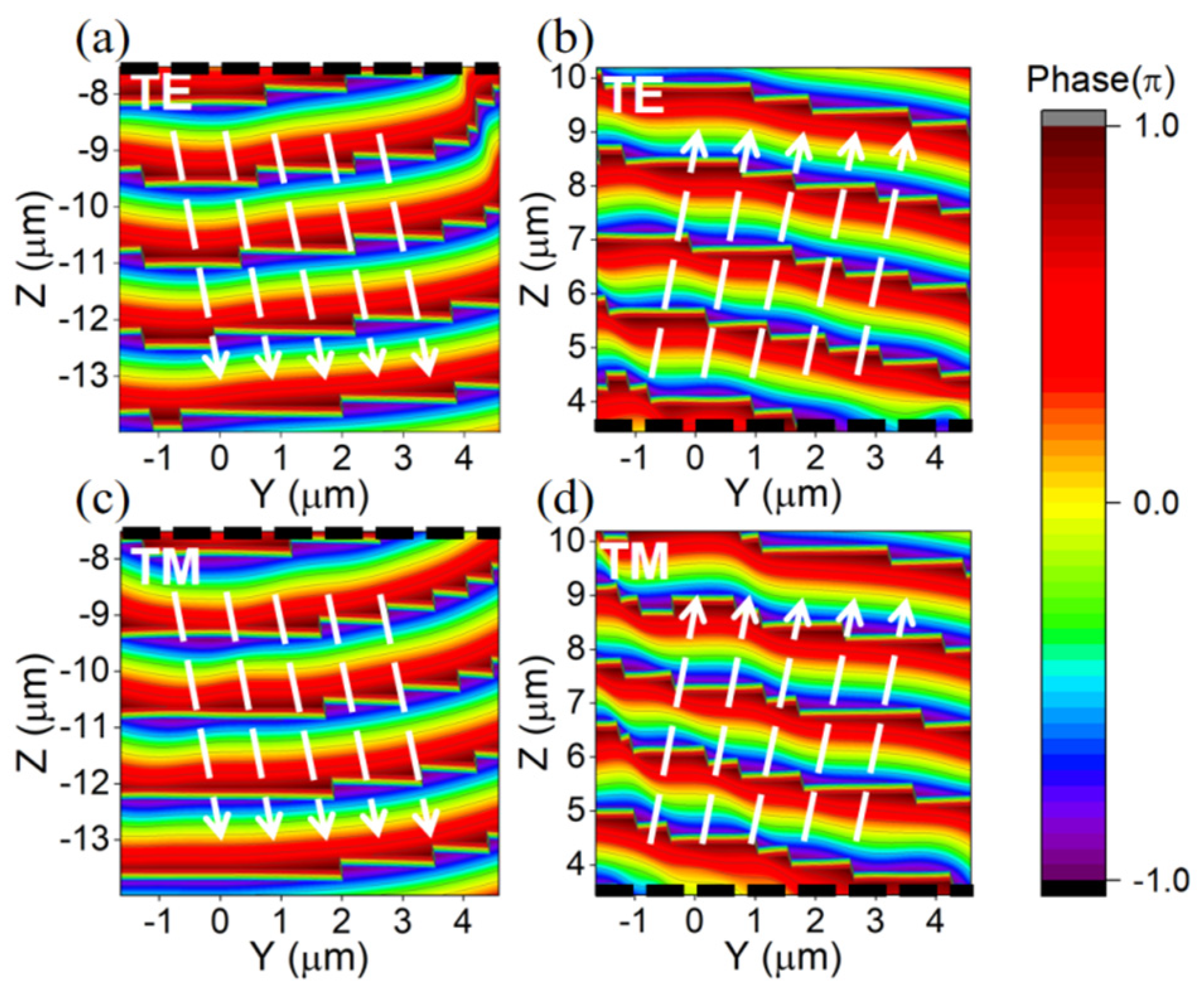
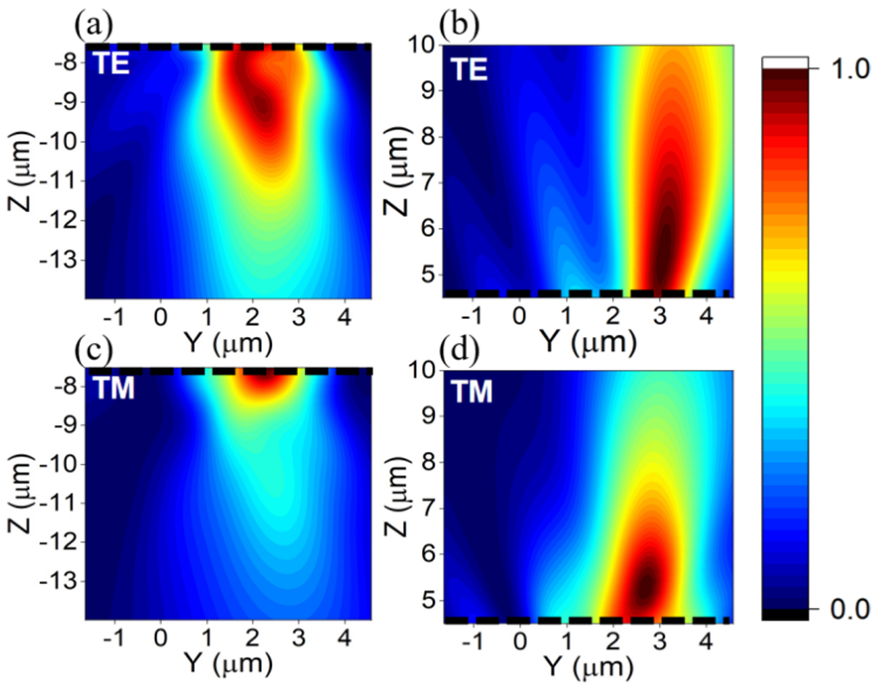
3. Simulation Results

When the light source is an x-polarized plane wave incident on the metasurface face along the positive z direction, the transmissive end and reflective end of the metasurface beam splitter exhibit an obvious isophase plane tilt phenomenon at 1.55 μm wavelength x-line polarized light (i.e., TE light) incidence, as shown in Figure 3, while the ratio of metasurface transmittance to reflectance is measured as 59%: 41%, which is close to the 1:1 splitting ratio.
Figure 3c,d show the incidence using y-line polarized light (i.e., TM light) of the same wavelength. They demonstrate an effect of isophase plane tilt, like x-line polarized light. Since the light emission direction of plane waves is generally perpendicular to the isophase plane, the designed metasurface produces an isophase plane with a certain slope at the transmissive and reflective ends to make outgoing light emerge at an angle, which in turn realizes the metasurface design’s deflection beam-splitting function for the incident light on the positive y-axis.
Figure 3. The Y−Z plane phase diagrams of the reflective and transmissive ends of the metasurface beam splitter under two types of line-polarized incident light at 1.55 μm wavelength reflect the isophase plane of the outgoing light waves, with white arrows in the direction of the isophase plane vertical line, a black dashed line being the light-emitting surface of the metasurface, and different color stratifications representing different isophase planes. (a) The isophase plane of the reflective end under the incident x-line polarized light. (b) The isophase plane of the transmissive end under the incident x-line polarized light. (c) The isophase plane of the reflective end under the incident y-line polarized light. (d) The isophase plane of the transmissive end under the incident y-line polarized light.
Applsci 13 05207 g003
In order to show the more intuitive light emission conditions at both ends of the metasurface under x and y-line polarization light incidence, we obtained the double-ended light field intensity distribution as shown in Figure 4. We can see the more obvious double-ended polarized light emission along the positive y-axis and located on the same side of the optical normal. To demonstrate the polarization-maintaining performance and the power variation of the BS, the polarization direction of the incident beam was changed from 0 degrees (x-line polarized light) to 90 degrees (y-line polarized light) in a step of 15 degrees.
As shown in Figure 5, the nanocolumn’s additional phase shows almost no change to different linear polarization lights. Due to the fact that circular and elliptical polarization lights can be decomposed into two orthogonal linear polarization lights, the nanocolumn could maintain the polarization characteristics of the arbitrary polarization beam. As shown in Figure 6, the splitting ratio changes from 59%:41% to 48%:52% with the variation of the polarization angle. This is due to the fact that although the individual metasurface unit cell is polarization-independent, the splitting ratio variation arises because of the spatially polarized difference in the X and Y directions for the overall structure after the arrangement. It also conforms to the characteristics of the BS device, which is sensitive to the angle of incident polarization and changes the splitting ratio without changing the polarization of the outgoing light.
To investigate the operation of this metasurface under other size conditions, we used the designed 5 μm × 5 μm metasurface as a benchmark and combined four such metasurfaces into a 10 μm × 10 μm metasurface array. Eventually, an isophase plane tilt circumstance appears at the transmissive end of the metasurface, as shown in Figure 7. This shows that different-sized metasurface arrays are likely to be constructed to match different-sized application conditions.
In order to calculate the double-ended outgoing angle, we normalized the intensity distribution near the maximum of the outgoing light field intensity along the y-axis and calculated the corresponding emergence angle, and the results are shown in Figure 8. The angle of emergence at the transmissive end is 9.2°, and it is 8.8° at the reflective end. According to Equation (3), the expected inclination angle of the isophase plane is 83.6°, and the propagation angle perpendicular to the isophase plane is 6.4°, which is similar to the simulation measurement results; at the same time, it is known that the maximum design deflection angle is 26.5°, which is reached when the additional phase difference is 2 π . The maximum deflection angle may be modified in the actual design by considering the metasurface material, the unit cell period, and the working waveband, all of which have certain design flexibility.
The tolerance of incident light angle change is an important performance indicator of beam splitters. Figure 9 simulates the double-ended isophase plane at various angles of the metasurface by continuously changing the incidence angle and then determining its operating angle bandwidth; isophase plane tilt effects are demonstrated at 0°~15° with the same effects as Figure 3 and Figure 4. When the incident angle increases to 16°, the reflective end does not exhibit the expected isophase plane tilt effect, as shown in Figure 9a. In order to further visualize the variation of the outgoing light at an incidence angle of 16°, we calculated the light field intensity distribution in the X−Y plane parallel to the reflective end of the metasurface at 0° and 16° incidence angles, respectively, and the final results are shown in Figure 10. It can be seen that at 0°, the reflective end basically behaves as a deflected outgoing light subject to phase modulation. Furthermore, at 16°, the modulated outgoing light disappears, and the reflective end completely behaves as directly reflected light from the metasurface substrate.
The simulation results show that the metasurface beam splitter has a large operating angle bandwidth of about 32° and that the deflection angle of the beam splitter does not change significantly with the incident angle, expressing strong operating stability.
Based on the planar distribution (like Figure 10) of the light field intensity at the maximum of the double-ended light field intensity and the light field intensity distribution near the point of the maximum intensity (like Figure 8), we can calculate the energy not involved in the deflected beam-splitting. The result is 6.7%, so the total splitting efficiency is 93.3%.
Figure 10. (a) The normalized intensity distribution of the light field in the X−Y plane when the incident light angle is 0° has a clear phenomenon of deflection out to the positive y-axis at the transmissive end. (b) The normalized intensity distribution of the light field in the X−Y plane when the incident light angle is 16°; the reflective end completely behaves as directly reflected light from the metasurface substrate.
Applsci 13 05207 g010
Table 2 summarizes some representative data for the diffraction efficiency of previous reports, including reflective and transmissive metasurface-based BSs (RMBS and TMBS). Compared to previous reports, our design achieves a similar theoretical TES value with a simpler structure, and the structural advantages of the transverse metasurface beam splitter are demonstrated to a certain extent.
To verify the above results, we also performed numerical simulation using the Finite Integration Technique (FIT) method and compared the decisive results obtained (as shown in Appendix A) with the FDTD method simulation results. Similar unit cell transmittance and phase variation curves indicate that the complete metasurface composed and characterized by unit cell structures should also have similar operating properties, which is confirmed by the similar metasurface double-ended isophase plane distribution. Therefore, we believe that the simulation comparison results in Appendix A can validate the correctness of the results in this paper.
In our tentative idea, the Si film grows on top of the whole SiO2 region by chemical vapor deposition (CVD). After spin-coating a layer of negative resist on the sample, electron-beam lithography (EBL) directly draws the patterns with nanoscale featured sizes and is followed by induced coupled plasma (ICP) silicon etching. Finally, when the remaining resist is cleared by the lift-off process, the designed transflective metasurface beam splitter is completed.

4. Conclusions

In this paper, we built and simulated an infrared all-dielectric metasurface beam splitter based on the structure of incomplete transmissive unit cells by arranging the metasurface with varied radii of silicon nanocolumns from small to large along the y-axis. The simulation confirms that the beam-splitting function is realized in the 1.55 μm infrared communication band with a splitting ratio close to 1:1, a deflection angle of approximately 9°, a theoretical total splitting efficiency of 93.3%, and an angular bandwidth of 32°. The correctness of the results was verified by comparing the simulation results, which were generated by two different numerical simulation methods. This double-ended modulated metasurface also generates a response at the input ends of the metasurface information compared to the existing single-ended phase-modulated metasurface. Therefore, the reflected phase-modulated light after beam-splitting can be used as a feedback signal to make real-time adjustments to the operating parameters of the optical system. Compared to other single-ended metasurface beam splitters, the use of light path conversion devices can be reduced, which can further increase the compactness of the optical system. It is hopeful to provide a new design method for metasurface applications in the fields of machine vision, optical measurement, and so on.

Author Contributions

Conceptualization, Y.R. and Z.L.; methodology, Y.R., Z.L., X.S., F.Y. and S.Z.; validation, Y.R. and F.Y.; formal analysis, Y.R., Z.L., X.S., F.Y. and W.L.; investigation, Y.R., X.S. and X.Z.; resources, Z.L.; data curation, Y.R. and Z.L.; writing—original draft preparation, Y.R.; writing—review and editing, Y.R., Z.L., F.Y., R.D., S.Z. and W.L.; visualization, Y.R. and X.Z.; supervision, Z.L., X.S. and R.D.; project administration, Z.L.; funding acquisition, Z.L. All authors have read and agreed to the published version of the manuscript.

Funding

National Natural Science Foundation of China (61735018); The Science Fund for Distinguished Young Scholars of Jilin Province (20230101351JC); Scientific and Technological Development Project of Jilin Province (20220201080GX); Excellent Member of the Youth Innovation Promotion Association of the Chinese Academy of Sciences (Y201836); Leading Talents and Team Project of Scientific and Technological Innovation for Young and Middle-aged Groups in Jilin Province (20190101012JH).

Institutional Review Board Statement

Not applicable.

Informed Consent Statement

Not applicable.

Data Availability Statement

Data is contained within the article.

Acknowledgments

The authors thank Yan Jia, Ningte Yan, Sixuan Li, and Zihan Wang of the Northeast Normal University for technical assistance in figure drawing and literature investigation.

Conflicts of Interest

The authors declare no conflict of interest.

Appendix A

Infrared all-dielectric metasurface beam splitter based on transflective structures. Related numerical simulation results by the Finite Integration Technique method:
Figure A1. The phase (red line) and transmittance curves (blue line) of outgoing light at 1.55 μm wavelength when the nanocolumn radius changes from 0.25 μm to 0.40 μm. The radius dimension points of the selected metasurface unit cell structure are marked in green.
Applsci 13 05207 g0a1
The above figure represents the transmittance and phase variation of different radius unit cells of the metasurface, and the overall results of the final metasurface are also based on the transmittance and phase characteristics of the unit cell. It can be seen that at several structural parameters selected in this paper (0.27 μm, 0.33 μm, 0.36 μm, 0.37 μm, and 0.38 μm), the simulation results of the FDTD method and the FIT method have similar transmittance and phase variation, so the overall metasurface composed of unit cells will also produce similar results.
Figure A2. The verification of the polarization-maintaining performance for the nanocolumn.
Applsci 13 05207 g0a2
From the above figure, we can know that the phase of the unit cell under the FIT method simulation also does not change with the polarization angle of the incident light, which shows the phase consistency of the metasurface under x-line polarized light incidence and y-line polarized light incidence.
Figure A3. The Y−Z plane phase diagrams of the reflective and transmissive ends of the metasurface beam splitter under two types of line-polarized incident light at 1.55 μm wavelength reflect the isophase plane of the outgoing light waves, with white arrows in the direction of the isophase plane vertical line, a black dashed line being the light-emitting surface of the metasurface, and different color stratifications representing different isophase planes. (a) The isophase plane of the reflective end under the incident x-line polarized light. (b) The isophase plane of the transmissive end under the incident x-line polarized light.
Applsci 13 05207 g0a3
As can be seen from the above figures, since the unit cell structure under the FIT method simulation shows a similar phase change as under the FDTD method simulation, the FIT method simulation results also exhibit an isophase plane tilt at the transmissive and reflective ends.

References

  1. Colace, L.; Sorianello, V.; Romagnoli, M.; Assanto, G. Near-Infrared Ge-on-Si Power Monitors Monolithically Integrated on SOI Chips. IEEE Photonics Technol. Lett. 2010, 22, 658–660. [Google Scholar] [CrossRef]
  2. Mekawey, H.; Elsayed, M.; Ismail, Y.; Swillam, M.A. Optical Interconnects Finally Seeing the Light in Silicon Photonics: Past the Hype. J. Nanomater. 2022, 12, 485. [Google Scholar] [CrossRef]
  3. Zhao, J.-H.; Li, X.-B.; Chen, Q.-D.; Chen, Z.-G.; Sun, H.-B. Ultrafast laser-induced black silicon, from micro-nanostructuring, infrared absorption mechanism, to high performance detecting devices. Mater. Today Nano 2020, 11, 100078. [Google Scholar] [CrossRef]
  4. Wang, Y.; Xie, F.; Ma, S.; Dong, L. Review of surface profile measurement techniques based on optical interferometry. Opt. Lasers Eng. 2017, 93, 164–170. [Google Scholar] [CrossRef]
  5. Wang, J.; He, S.; Dai, D. On-chip silicon 8-channel hybrid (de)multiplexer enabling simultaneous mode- and polarization-division-multiplexing. Laser Photonics Rev. 2014, 8, L18–L22. [Google Scholar] [CrossRef]
  6. Liu, D.; Hostetler, C.; Miller, I.; Cook, A.; Hair, J. System analysis of a tilted field-widened Michelson interferometer for high spectral resolution lidar. Opt. Express 2012, 20, 1406–1420. [Google Scholar] [CrossRef]
  7. Vlasov, S.N.; Katin, S.V.; Koposova, E.V.; Lubyako, L.V.; Prokofyev, L.I. Quasioptical Mach—Zehnder Interferometer with a Reflective Diffraction Grating Acting as a Power Splitter. Radiophys. Quantum Electron. 2016, 59, 137–144. [Google Scholar] [CrossRef]
  8. Phongwisit, P.; Kamoldilok, S.; Buranasiri, P.; Srinuanjan, K.; Limsuwan, P. Design and simulation of asymmetric Y-junction beam splitter with controllable splitting based on adjusted air-hole defect. Ukr. J. Phys. Opt. 2022, 23, 142–149. [Google Scholar] [CrossRef]
  9. Yang, G.; Sergienko, A.V.; Ndao, A. Plasmonic loss-mitigating broadband adiabatic polarizing beam splitter. Opt. Lett. 2022, 47, 629–632. [Google Scholar] [CrossRef]
  10. Noori, M.; Soroosh, M.; Baghban, H. Design of highly efficient polarization beam splitter based on self-collimation on Si platform. J. Mod. Opt. 2016, 64, 491–499. [Google Scholar] [CrossRef]
  11. Razmi, H.; Soroosh, M.; Kavian, Y.S. A New Proposal for Ultra-Compact Polarization Independent Power Splitter Based on Photonic Crystal Structures. Opt. Commun. 2018, 39, 375–379. [Google Scholar] [CrossRef]
  12. Ghosh, N.; Bhattacharya, K. Cube beam-splitter interferometer for phase shifting interferometry. J. Opt. 2009, 38, 191–198. [Google Scholar] [CrossRef]
  13. Chung, K.; Chan, H.P.; Chu, P.L. A1×4 polarization and wavelength independent optical power splitter based on a novel wide-angle low-loss Y-junction. Opt. Commun. 2006, 267, 367–372. [Google Scholar] [CrossRef]
  14. Wang, J.; Guan, X.; He, Y.; Shi, Y.; Wang, Z.; He, S.; Holmström, P.; Wosinski, L.; Thylén, L.; Dai, D. Sub-μm2 power splitters by using silicon hybrid plasmonic waveguides. Opt. Express 2011, 19, 838–847. [Google Scholar] [CrossRef]
  15. Ye, C.; Dai, D. Ultra-Compact Broadband 2 × 2 3dB Power Splitter Using a Subwavelength-Grating-Assisted Asymmetric Directional Coupler. J. Light. Technol. 2020, 38, 2370–2375. [Google Scholar] [CrossRef]
  16. Rizea, A. Design technique for all-dielectric non-polarizing beam splitter plate. Opto-Electron. Rev. 2012, 20, 96–99. [Google Scholar] [CrossRef]
  17. Feng, J.; Zhou, Z. Polarization beam splitter using a binary blazed grating coupler. Opt. Lett. 2007, 32, 1662–1664. [Google Scholar] [CrossRef] [PubMed]
  18. Karar, V.; Sharma, A.L. Design and Fabrication of Multilayer Dichroic Beam Splitter. Adv. Mater. Proc. 2017, 2, 398. [Google Scholar]
  19. Deng, L.; Deng, J.; Guan, Z.; Tao, J.; Chen, Y.; Yang, Y.; Zhang, D.; Tang, J.; Li, Z.; Li, Z.; et al. Malus-metasurface-assisted polarization multiplexing. Light Sci. Appl. 2020, 9, 101. [Google Scholar] [CrossRef]
  20. Qin, Z.; Meng, D.; Yang, F.; Shi, X.Y.; Liang, Z.; Xu, H.; Smith, D.R.; Liu, Y. Broadband long-wave infrared metamaterial absorber based on single-sized cut-wire resonators. Opt. Express 2021, 29, 20275–20285. [Google Scholar] [CrossRef]
  21. Liu, M.; Zhu, W.; Huo, P.; Feng, L.; Song, M.; Zhang, C.; Chen, L.; Lezec, H.J.; Lu, Y.; Agrawal, A.; et al. Multifunctional metasurfaces enabled by simultaneous and independent control of phase and amplitude for orthogonal polarization states. Light Sci. Appl. 2021, 10, 107. [Google Scholar] [CrossRef] [PubMed]
  22. Zhang, C.; Divitt, S.; Fan, Q.; Zhu, W.; Agrawal, A.; Lu, Y.; Xu, T.; Lezec, H.J. Low-loss metasurface optics down to the deep ultraviolet region. Light Sci. Appl. 2020, 9, 55. [Google Scholar] [CrossRef]
  23. Wang, J.; Du, J. Plasmonic and Dielectric Metasurfaces: Design, Fabrication and Applications. Appl. Sci. 2016, 6, 239. [Google Scholar] [CrossRef]
  24. Ding, F.; Yang, Y.; Deshpande, R.A.; Bozhevolnyi, S.I. A review of gap-surface plasmon metasurfaces: Fundamentals and applications. Nanophotonics 2018, 7, 1129–1156. [Google Scholar] [CrossRef]
  25. Luo, S.; Hoff, B.H.; Maier, S.A.; de Mello, J.C. Scalable Fabrication of Metallic Nanogaps at the Sub-10 nm Level. Adv. Sci. 2021, 8, 2102756. [Google Scholar] [CrossRef]
  26. Hua, X.; Wang, Y.; Wang, S.; Zou, X.; Zhou, Y.; Li, L.; Yan, F.; Cao, X.; Xiao, S.; Tsai, D.P.; et al. Ultra-compact snapshot spectral light-field imaging. Nat. Commun. 2022, 13, 2732. [Google Scholar] [CrossRef] [PubMed]
  27. Thureja, P.; Sokhoyan, R.; Hail, C.U.; Sisler, J.; Foley, M.; Grajower, M.Y.; Atwater, H.A. Toward a universal metasurface for optical imaging, communication, and computation. Nanophotonics 2022, 11, 3745–3768. [Google Scholar] [CrossRef]
  28. Wu, Z.; Zhang, Z.; Xu, Y.; Zhai, Y.; Zhang, C.; Wang, B.; Wang, Q. Random color filters based on an all-dielectric metasurface for compact hyperspectral imaging. Opt. Lett. 2022, 47, 4548–4551. [Google Scholar] [CrossRef] [PubMed]
  29. Liu, C.; Ma, Q.; Luo, Z.J.; Hong, Q.R.; Xiao, Q.; Zhang, H.C.; Miao, L.; Yu, W.M.; Cheng, Q.; Li, L.; et al. A programmable diffractive deep neural network based on a digital-coding metasurface array. Nat. Electron. 2022, 5, 113–122. [Google Scholar] [CrossRef]
  30. Sun, K.; Xiao, W.; Wheeler, C.; Simeoni, M.; Urbani, A.; Gaspari, M.; Mengali, S.; de Groot, C.H.; Muskens, O.L.J.N. VO2 metasurface smart thermal emitter with high visual transparency for passive radiative cooling regulation in space and terrestrial applications. Nanophotonics 2022, 11, 4101–4114. [Google Scholar] [CrossRef]
  31. Xie, X.; Liu, K.; Pu, M.; Ma, X.; Li, X.; Guo, Y.; Zhang, F.; Luo, X. All-metallic geometric metasurfaces for broadband and high-efficiency wavefront manipulation. Nanophotonics 2020, 9, 3209–3215. [Google Scholar] [CrossRef]
  32. He, Y.; Xie, Z.; Yang, B.; Chen, X.; Liu, J.; Ye, H.; Zhou, X.; Li, Y.; Chen, S.; Fan, D. Controllable photonic spin Hall effect with phase function construction. Photonics Res. 2020, 8, 963–971. [Google Scholar] [CrossRef]
  33. Genevet, P.; Capasso, F. Holographic optical metasurfaces: A review of current progress. Rep. Prog. Phys. 2015, 78, 024401. [Google Scholar] [CrossRef] [PubMed]
  34. Xie, Z.-Q.; He, Y.-L.; Wang, P.-P.; Su, M.-Y.; Chen, X.-Y.; Yang, B.; Liu, J.-M.; Zhou, X.-X.; Li, Y.; Chen, S.-Q.; et al. Two-dimensional optical edge detection based on Pancharatnam-Berry phase metasurface. Acta Phys. Sin. 2020, 69, 014101. [Google Scholar]
  35. Hao, H.; Tang, Y.; Zheng, S.; Ran, X. Design of metasurface beam splitter based on polarization characteristics of incident wave. J. Electromagn. Waves Appl. 2021, 36, 307–320. [Google Scholar] [CrossRef]
  36. Chen, X.; Zou, H.; Su, M.; Tang, L.; Wang, C.; Chen, S.; Su, C.; Li, Y. All-Dielectric Metasurface-Based Beam Splitter with Arbitrary Splitting Ratio. Nanomaterials 2021, 11, 1137. [Google Scholar] [CrossRef] [PubMed]
  37. Tian, T.; Liao, Y.; Feng, X.; Cui, K.; Liu, F.; Zhang, W.; Huang, Y. Metasurface-Based Free-Space Multi-port Beam Splitter with Arbitrary Power Ratio. physics. Optics 2023, 2212, 01009. [Google Scholar]
  38. Khorasaninejad, M.; Zhu, A.Y.; Roques-Carmes, C.; Chen, W.T.; Oh, J.; Mishra, I.; Devlin, R.C.; Capasso, F. Polarization-Insensitive Metalenses at Visible Wavelengths. Nano Lett. 2016, 16, 7229–7234. [Google Scholar] [CrossRef]
  39. Ziolkowski, R.W.; Engheta, N. Metamaterials: Two Decades Past and Into Their Electromagnetics Future and Beyond. IEEE Trans. Antennas Propag. 2020, 68, 1232–1237. [Google Scholar] [CrossRef]
  40. Yu, N.; Genevet, P.; Kats, M.A.; Aieta, F.; Tetienne, J.-P.; Capasso, F.; Gaburro, Z. Light Propagation with Phase Discontinuities: Generalized Laws of Reflection and Refraction. Science 2011, 334, 333–337. [Google Scholar] [CrossRef]
  41. Lim, S.W.D.; Meretska, M.L.; Capasso, F. A High Aspect Ratio Inverse-Designed Holey Metalens. Nano Lett. 2021, 21, 8642–8649. [Google Scholar] [CrossRef] [PubMed]
  42. Zhang, X.; Deng, R.; Yang, F.; Jiang, C.; Xu, S.; Li, M. Metasurface-Based Ultrathin Beam Splitter with Variable Split Angle and Power Distribution. ACS Photonics 2018, 5, 2997–3002. [Google Scholar] [CrossRef]
  43. Sell, D.; Yang, J.; Wang, E.; Phan, T.; Doshay, S.; Fan, J. Ultra-High-Efficiency Anomalous Refraction with Dielectric Metasurfaces. ACS Photonics 2018, 5, 2402–2407. [Google Scholar] [CrossRef]
  44. Wang, Z.; Dai, C.; Li, Z.; Li, Z. Free-Space Optical Merging via Meta-Grating Inverse-Design. Nano Lett. 2022, 22, 2059–2064. [Google Scholar] [CrossRef] [PubMed]
Figure 2. (a) The phase (red line) and transmittance curves (blue line) of outgoing light at 1.55 μm wavelength when the nanocolumn radius changes from 0.15 μ m to 0.45 μm. The radius dimension points of the selected metasurface unit cell structure are marked in green. (b) The transmittance curves corresponding to different distances of nanocolumns.
Applsci 13 05207 g002
Figure 4. The normalized intensity of the Y−Z plane at the reflective and transmissive ends of the metasurface beam splitter under the incidence of x-polarized light at 1.55 μm wavelength demonstrates the deflection of the outgoing light. (a) The intensity of the Y−Z plane at the reflective end of the metasurface beam splitter under the incoming x-polarized light of 1.55 μm wavelength. (b) The intensity of the Y−Z plane at the transmissive end of the metasurface beam splitter under the incoming x-polarized light of 1.55 μm wavelength. (c) The intensity of the Y−Z plane at the reflective end of the metasurface beam splitter under the incoming y-polarized light of 1.55 μm wavelength. (d) The intensity of the Y−Z plane at the transmissive end of the metasurface beam splitter under the incoming y-polarized light at 1.55 μm.
Applsci 13 05207 g004
Figure 5. The verification of the polarization-maintaining performance of the nanocolumn.
Applsci 13 05207 g005
Figure 6. The variation of transmittance and reflectance with the polarization angle.
Applsci 13 05207 g006
Figure 7. The isophase plane at the transmissive end of the metasurface array under the incident x-line polarized light, with white arrows in the direction of the isophase plane vertical line, a black dashed line being the light-emitting surface of the metasurface, and different color stratifications representing different isophase planes.
Applsci 13 05207 g007
Figure 8. The double-ended normalized intensity distribution at different emergence angles.
Applsci 13 05207 g008
Figure 9. (a) Phase diagram of the Y−Z plane at the reflective end of the metasurface under 16° incidence of 1.55 μm x-line polarized light. The influence of the isophase tilt is no longer apparent. (b) Phase diagram of the metasurface’s transmissive end Y−Z plane under a 16° incidence of 1.55 μm x-line polarized light.
Applsci 13 05207 g009
Table 2. Some data for the total splitting efficiency of previous reports.
Reference YearTypeTES
2018 [42]RMBS20.3%
2018 [43]TMBS60~80%
2021 [36]TMBS93.21% (theory)
2022 [44]RMBS62~75%
2023 [37]TMBS93.6% (theory)
78.3 (actuality)
Disclaimer/Publisher’s Note: The statements, opinions and data contained in all publications are solely those of the individual author(s) and contributor(s) and not of MDPI and/or the editor(s). MDPI and/or the editor(s) disclaim responsibility for any injury to people or property resulting from any ideas, methods, instructions or products referred to in the content.

