
Out-of-Plane Stability of Circular Steel Tubular Vierendeel Truss Arches Incorporating Torsional Effects of Chords

Abstract
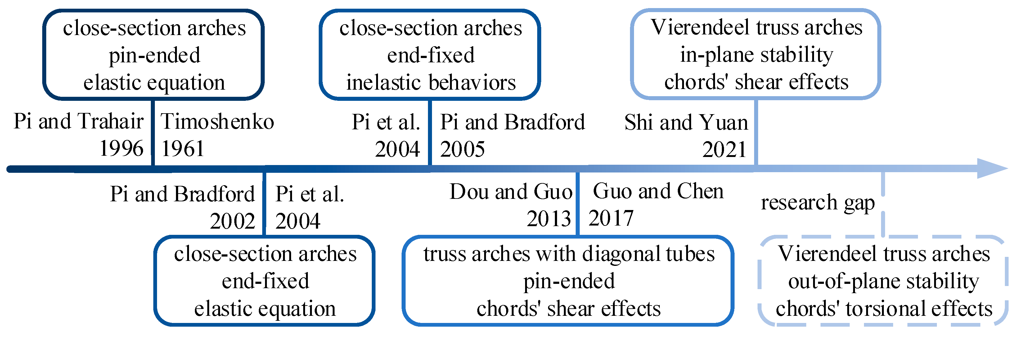
:1. Introduction

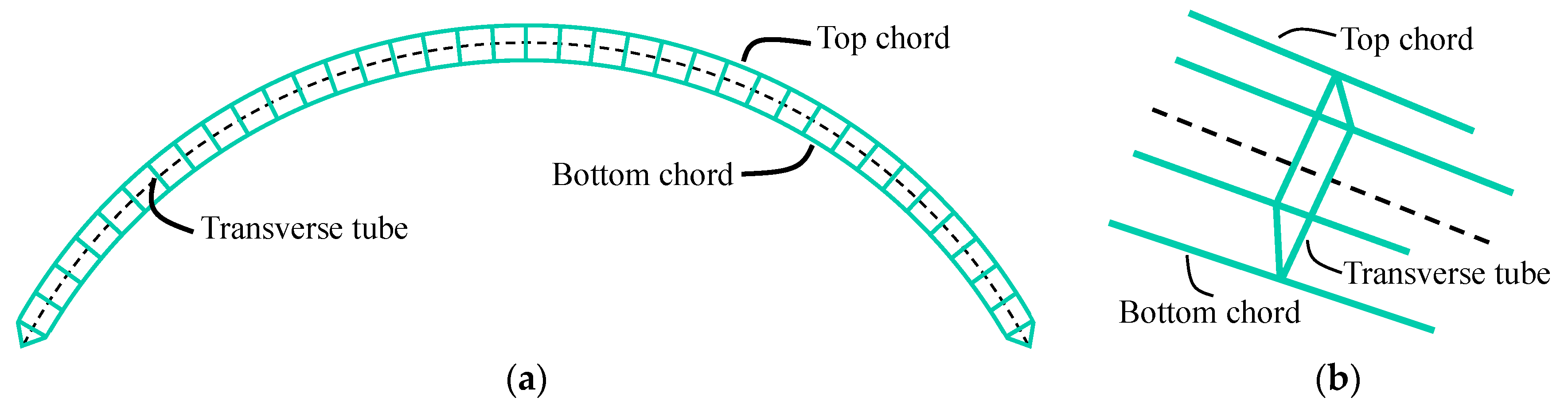
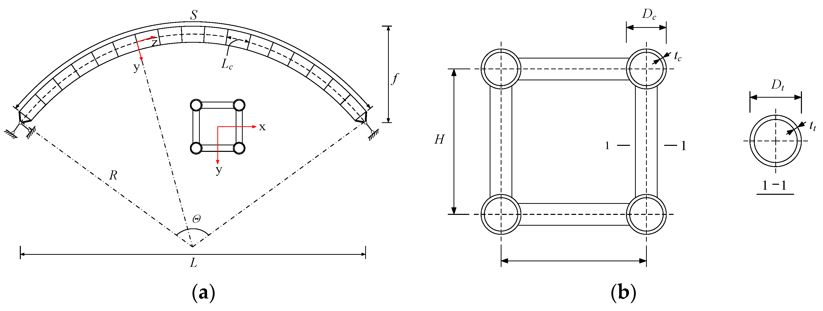
2. Finite Element Models
3. Sectional Stiffnesses in Vierendeel Truss Arches
3.1. Sectional Bending Stiffness and Sectional Shear Stiffness
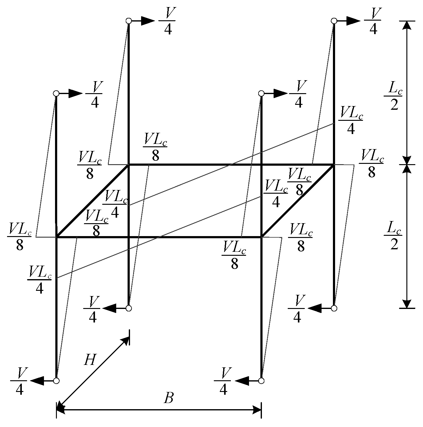
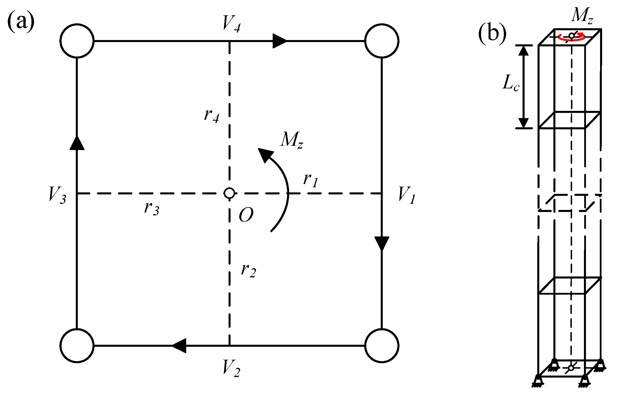
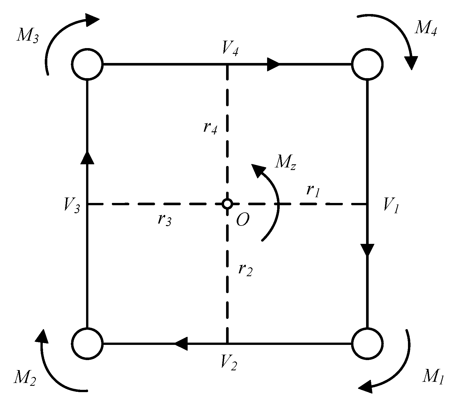
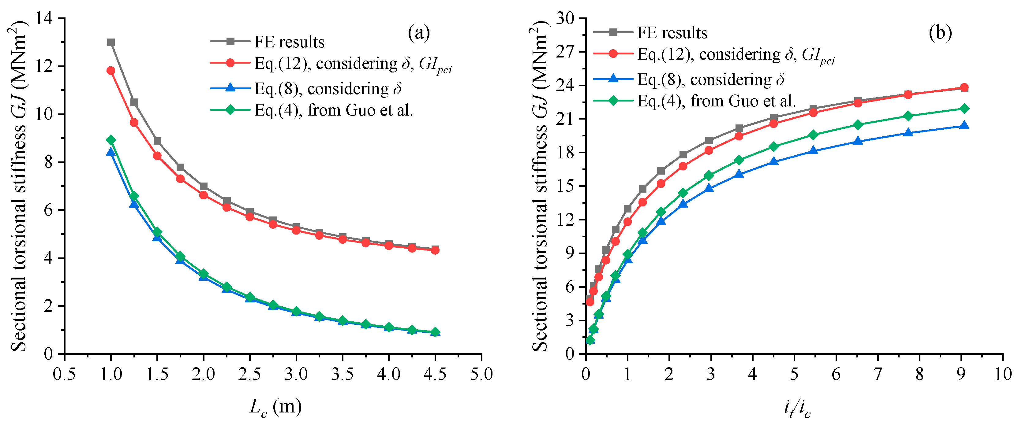
3.2. Sectional Torsional Stiffness
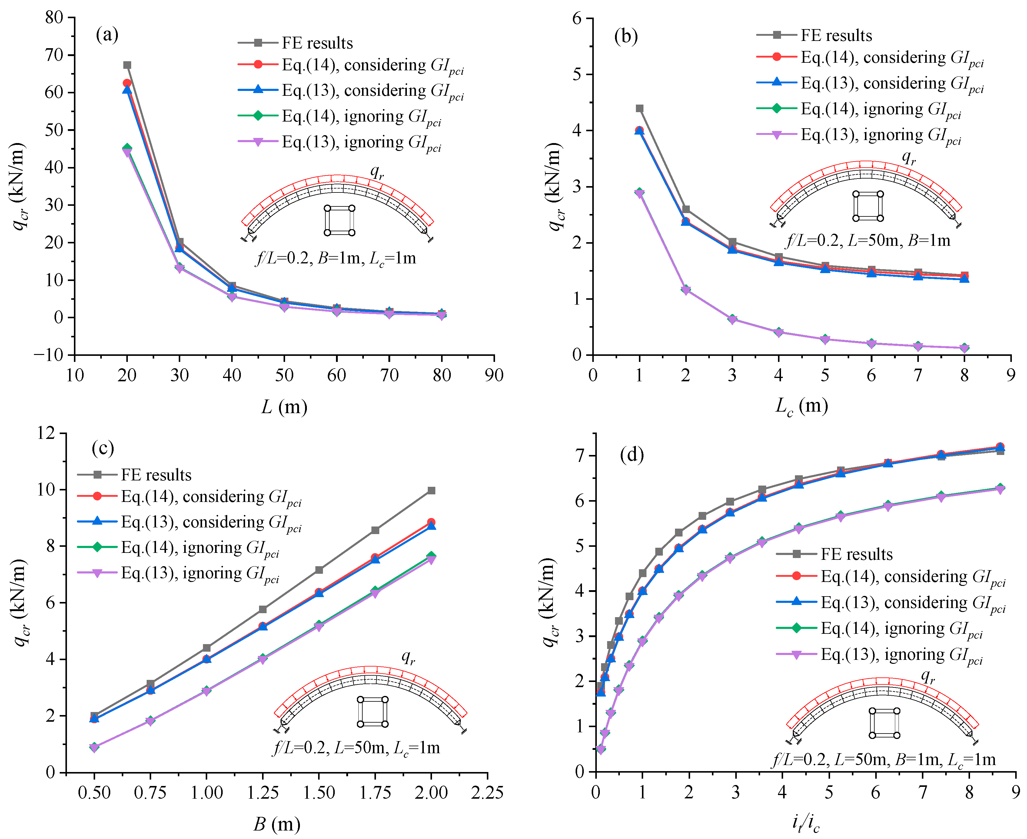
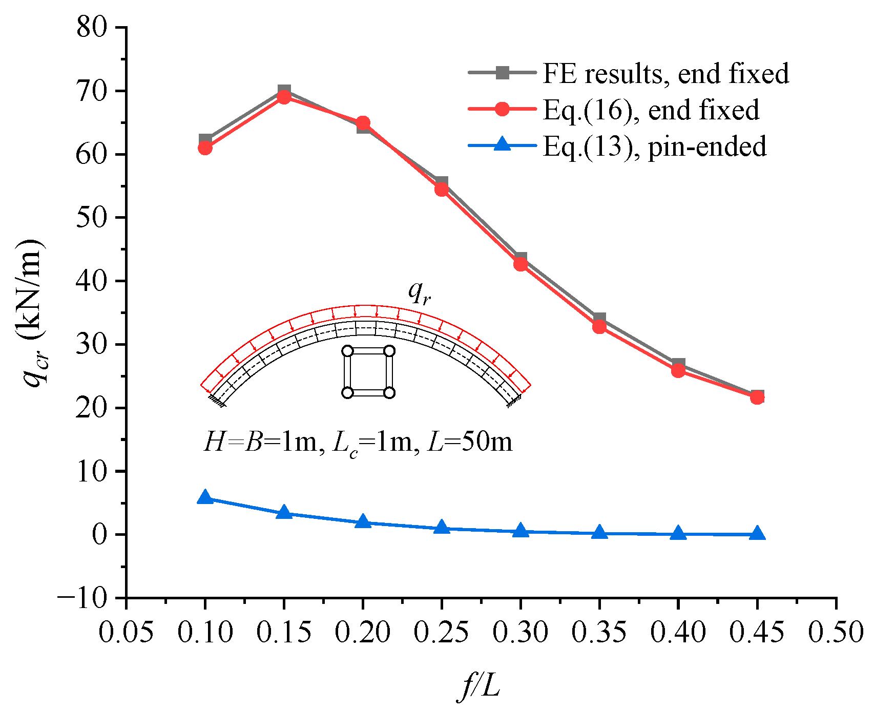
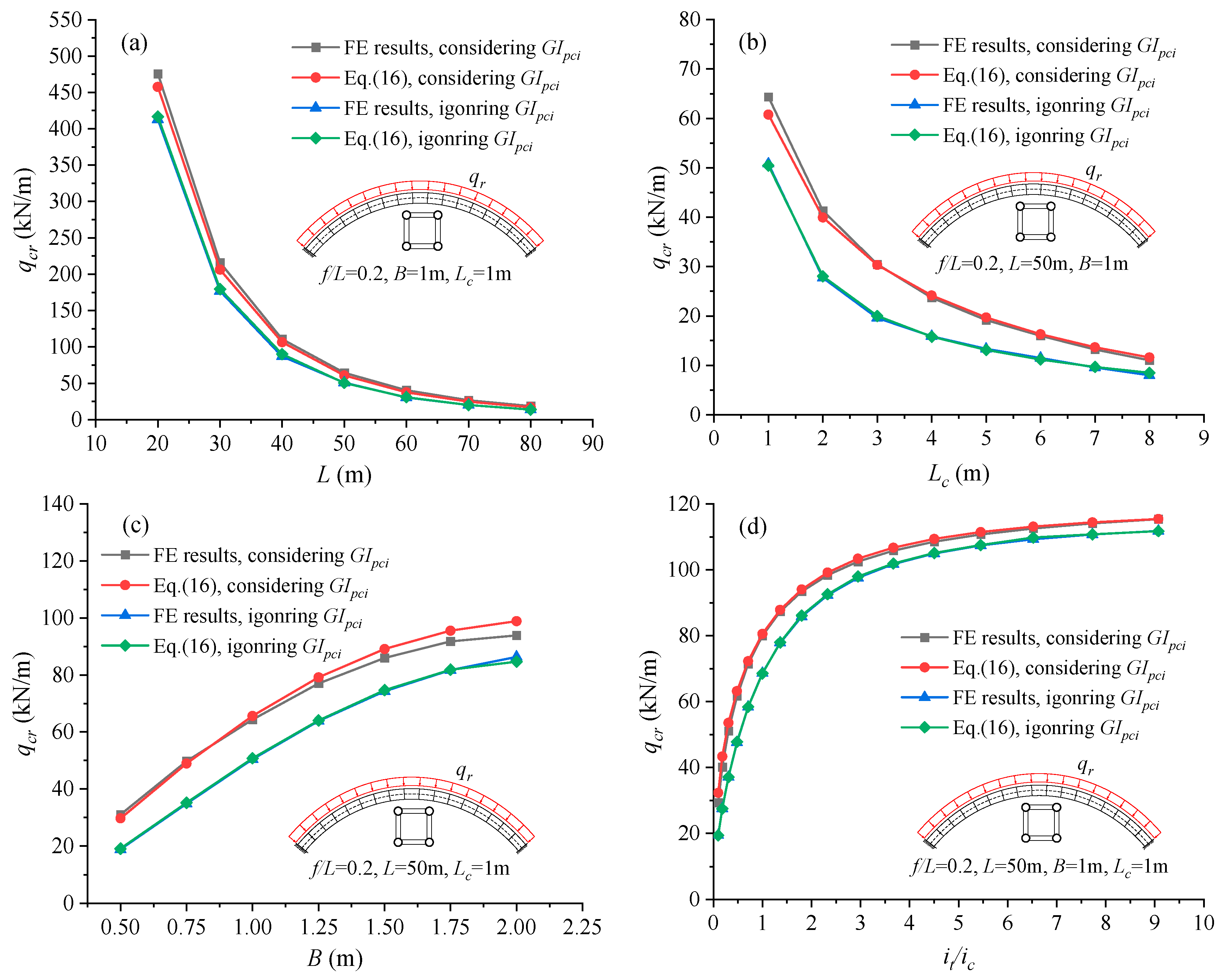
4. Out-of-Plane Elastic Buckling Load of Vierendeel Truss Arches
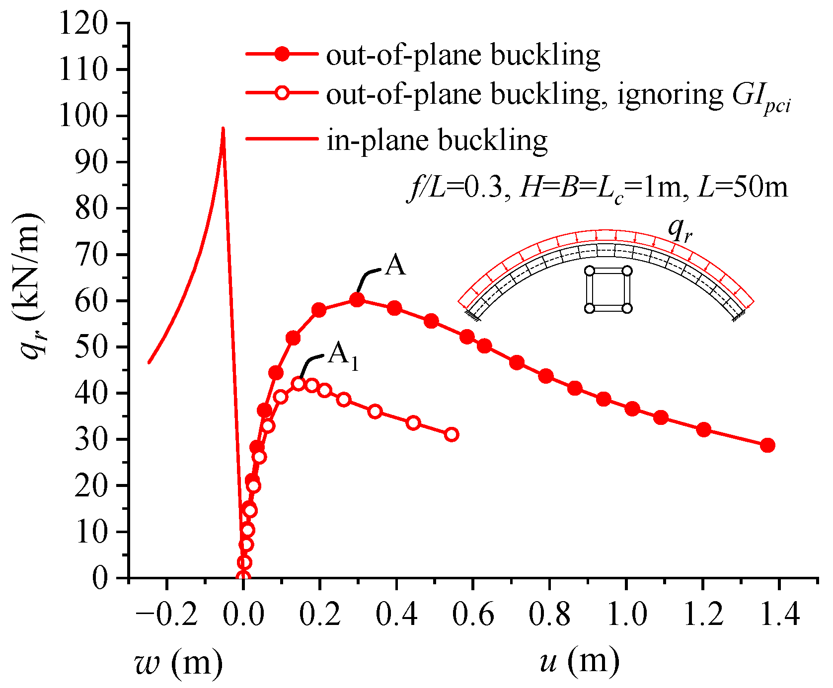
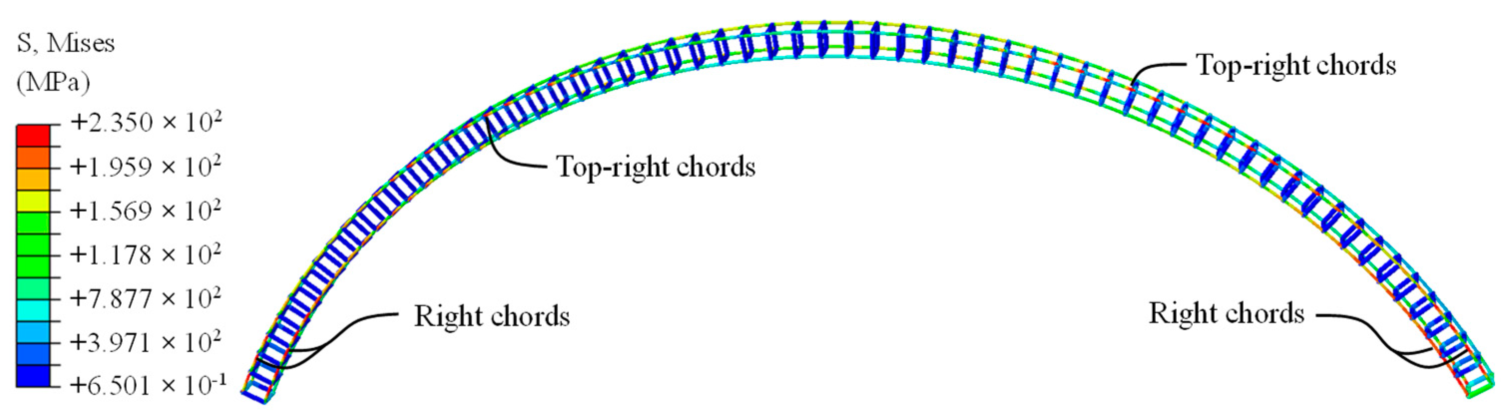
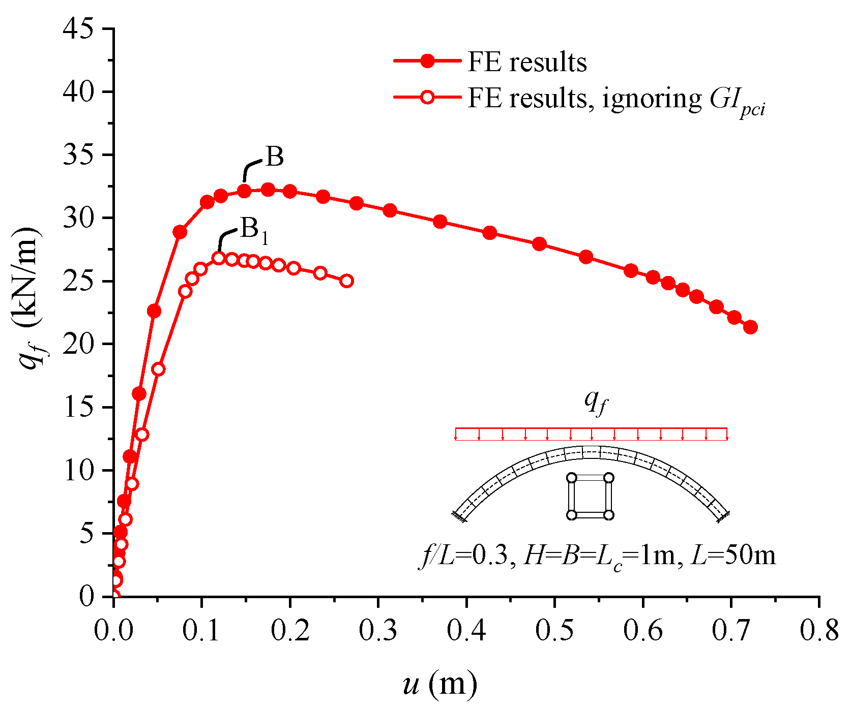
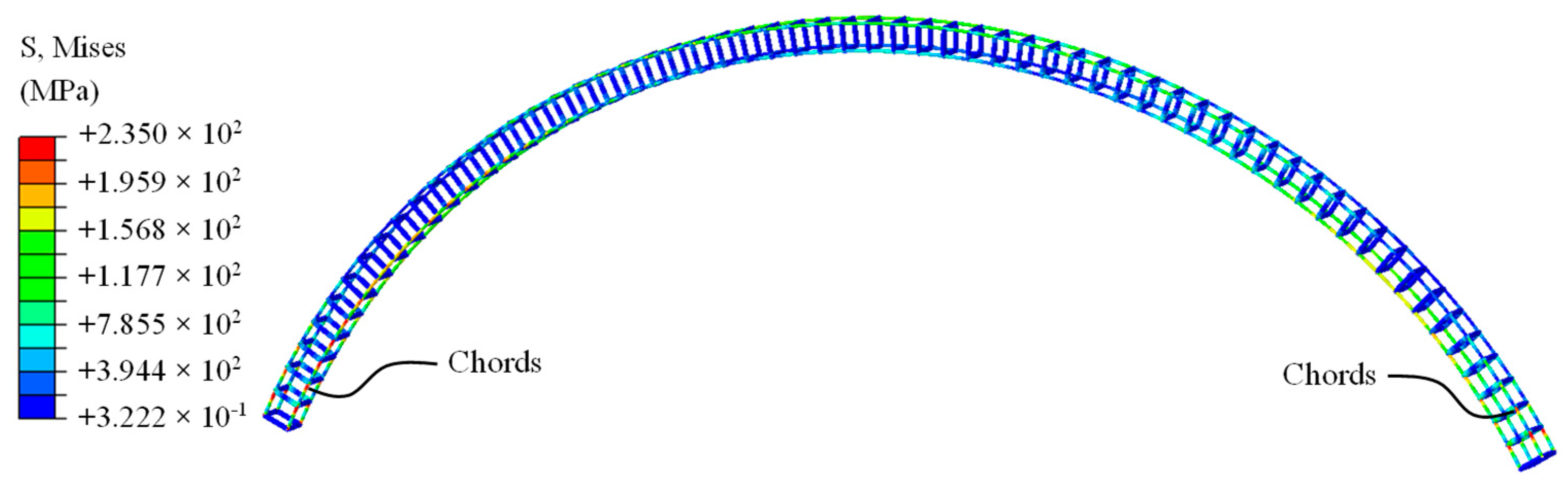
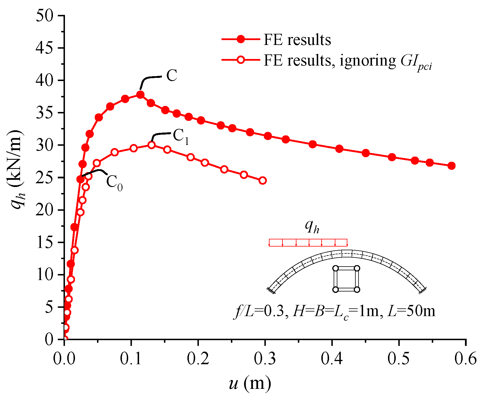
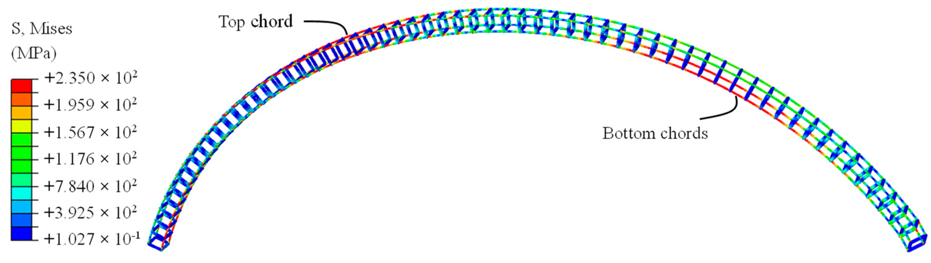
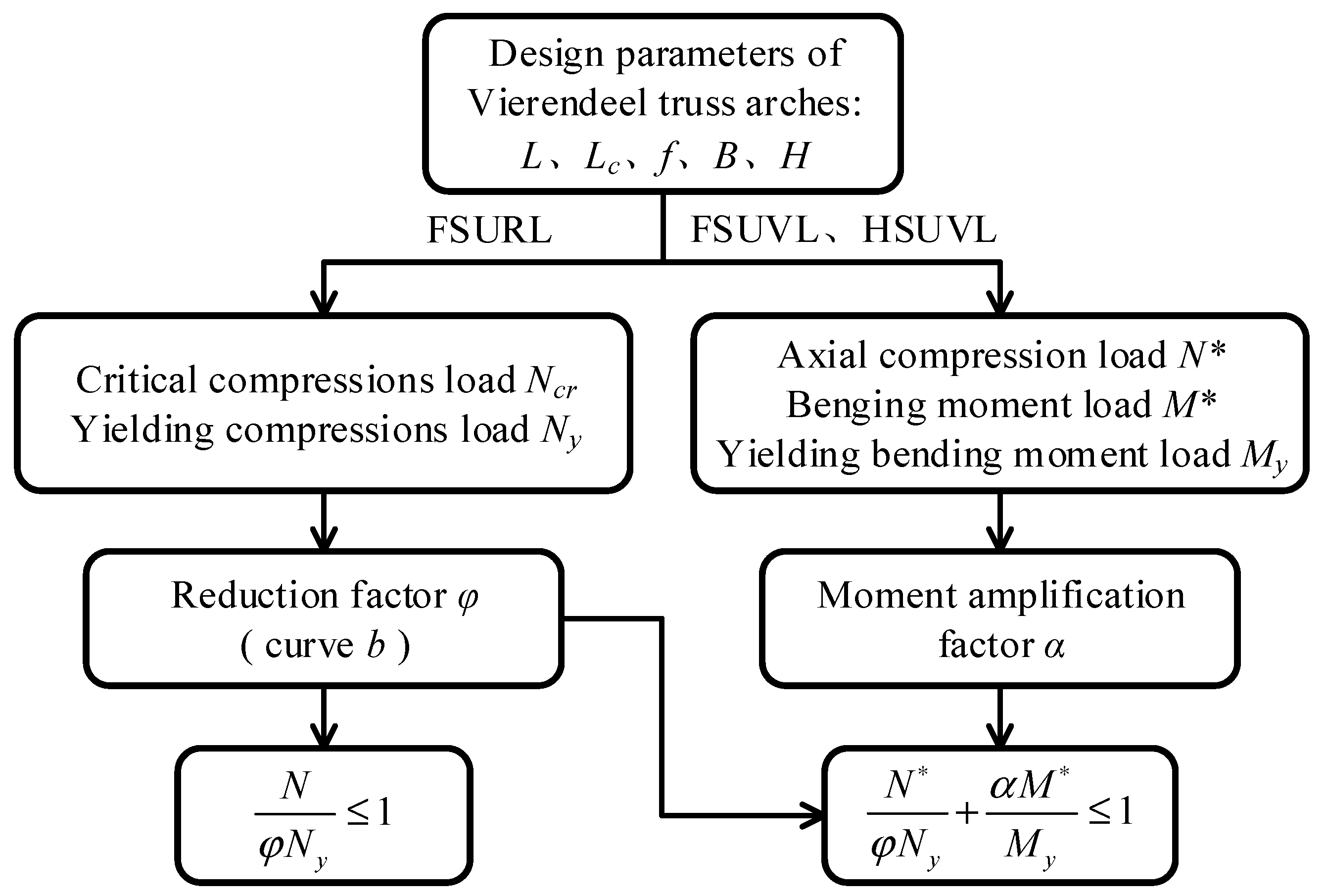
5. Out-of-Plane Inelastic Buckling Behaviors of Vierendeel Truss Arches
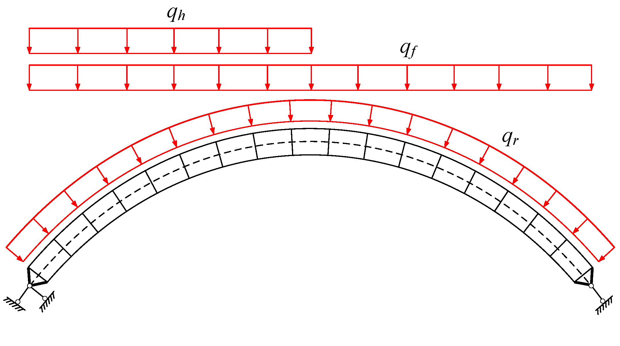
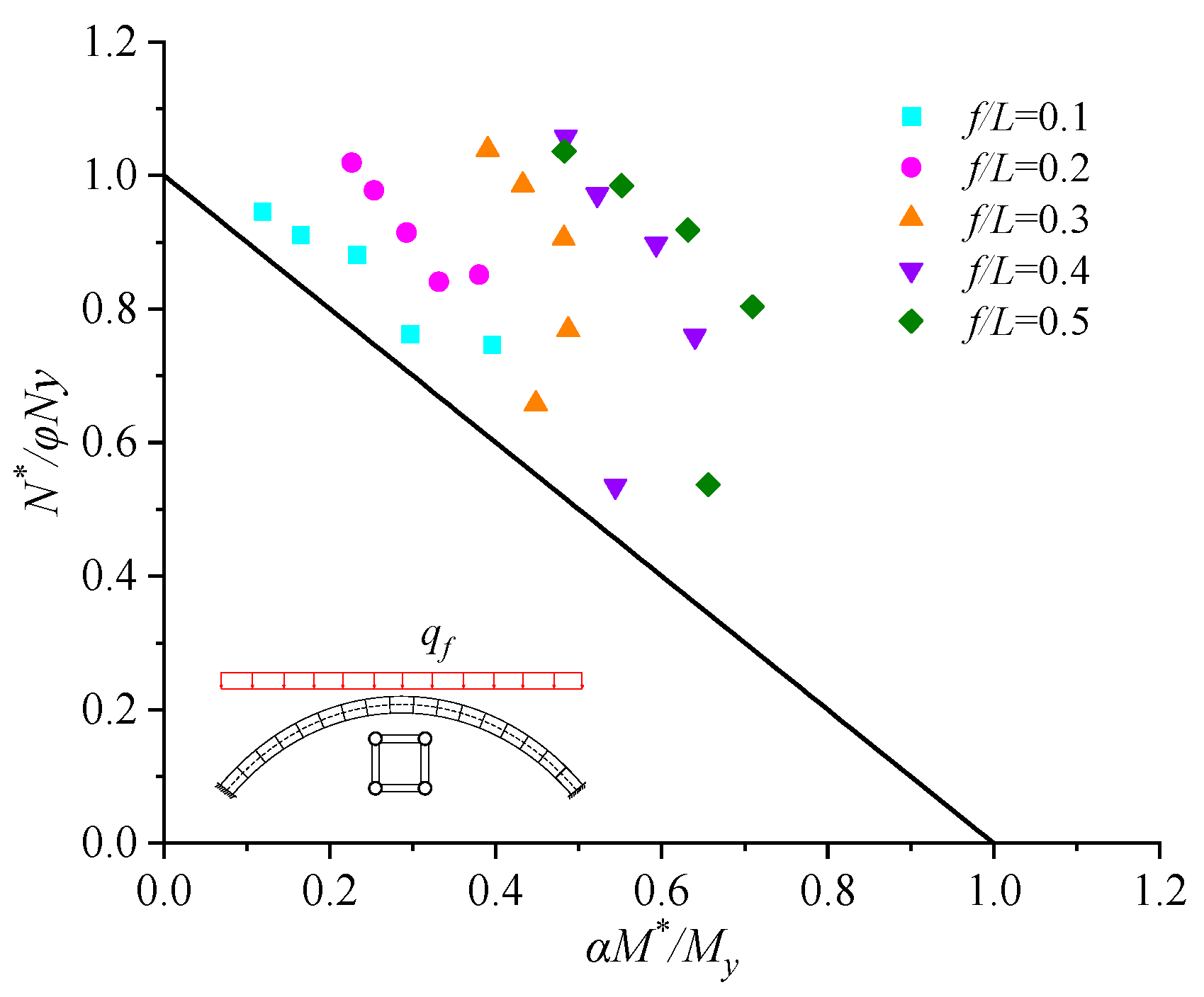
5.1. Cases under the FSURL
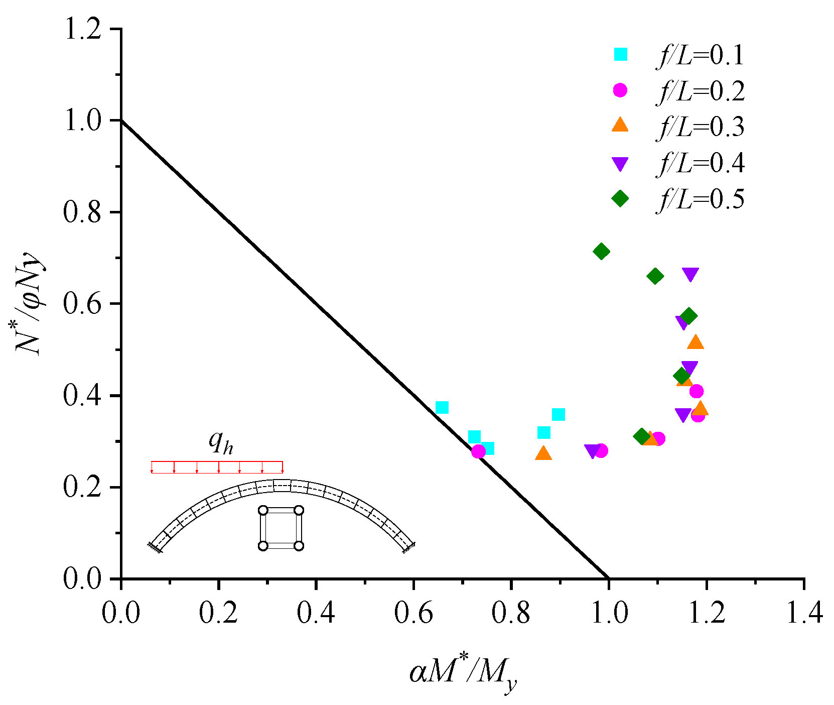
5.2. Cases under the FSUVL
5.3. Cases under the HSUVL
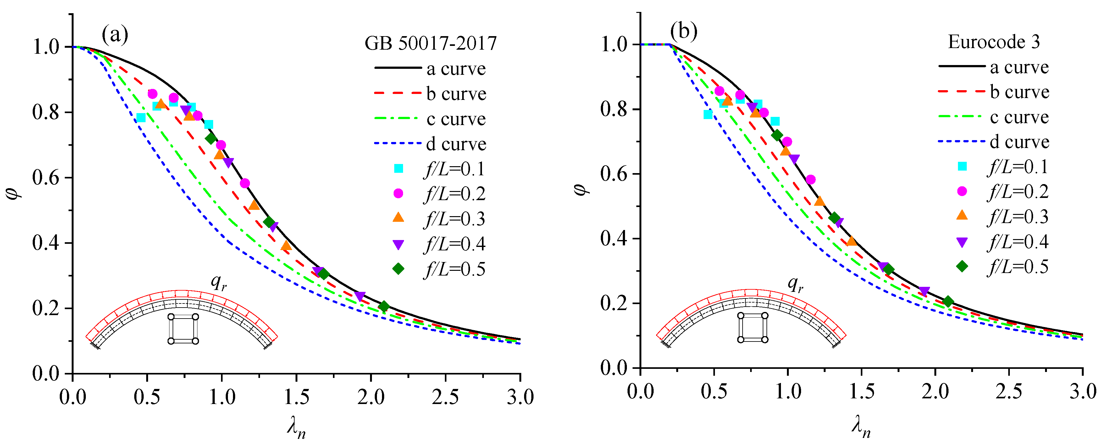
6. Conclusions
- The sectional torsional stiffness of the pin-ended circular steel tubular Vierendeel truss arches decreases with the segment length but increases with the transverse-to-chord member stiffness ratio (it/ic). Incorporating the torsional stiffness of individual chords can remarkably enhance the sectional torsional stiffness of the Vierendeel truss arches.
- The out-of-plane elastic buckling loads of the circular Vierendeel truss arches, either the pin-ended cases derived by the equilibrium theorem, or the fix-ended cases derived by the numerical fitting, increase significantly when the torsional stiffness of each chord is taken into account. The dependence of the out-of-plane buckling load, similar to that of the sectional torsional stiffness on it/ic, is observed in both the pin-ended and the end-fixed Vierendeel truss arches.
- For the fixed Vierendeel truss arches with large it/ic, the local yielding of chords occurs before the global buckling. Incorporating the torsional stiffness of chords will remarkably increase the ultimate buckling loads of arches under different loading cases (FSURL, FSUVL, and HSUVL). The curve b from the design codes (GB50017-2017 or Eurocode 3) can provide a lower bound prediction of the reduction factors for the out-of-plane stability design of the end-fixed Vierendeel truss arches.
Author Contributions
Funding
Institutional Review Board Statement
Informed Consent Statement
Data Availability Statement
Conflicts of Interest
Appendix A

| Equation (3) | Sectional shear stiffness considering δ | |
| Equation (4) | Sectional torsional stiffness ignoring δ and GIpc | |
| Equation (8) | Sectional torsional stiffness considering δ | |
| Equation (12) | Sectional torsional stiffness considering δ and GIpc | |
| Equation (13) | Dou’s equation of critical buckling load for pin-ended arches | |
| Equation (14) | Kirchhoff’s equation of critical buckling load for pin-ended arches | |
| Equation (16) | Numerically fitted equation of critical buckling load for end-fixed arches |
References
- Tianfu Agricultural Expo Main Hall—The Institution of Structural Engineers. Available online: http://www.istructe.org/structural-awards/projects/2022/tianfu-agricultural-expo-main-hall/ (accessed on 15 April 2023).
- Chen, S. Analysis of longitudinally symmetrical vierendeel girders by the theorem of three shears. J. ICE 1948, 30, 192–194. [Google Scholar] [CrossRef]
- Shehata, A.A.; Korol, R.M.; Mirza, F.A. Joint Flexibility Effects on Rectangular Hollow Section Vierendeel Trusses. Mech. Based Des. Struct. Mach. 1987, 15, 89–107. [Google Scholar] [CrossRef]
- Pi, Y.-L.; Trahair, N.S. In-Plane Buckling and Design of Steel Arches. J. Struct. Eng. 1999, 125, 1291–1298. [Google Scholar] [CrossRef]
- Pi, Y.-L.; Trahair, N.S. In-Plane Inelastic Buckling and Strengths of Steel Arches. J. Struct. Eng. 1996, 122, 734–747. [Google Scholar] [CrossRef]
- Pi, Y.-L.; Bradford, M.A. In-plane strength and design of fixed steel I-section arches. Eng. Struct. 2004, 26, 291–301. [Google Scholar] [CrossRef]
- Pi, Y.L.; Bradford, M.A.; Uy, B. In-plane stability of arches. Int. J. Solids Struct. 2002, 39, 105–125. [Google Scholar] [CrossRef]
- Guo, Y.-L.; Yuan, X.; Bradford, M.A.; Pi, Y.-L.; Chen, H. Strength design of pin-ended circular steel arches with welded hollow section accounting for web local buckling. Thin. Wall. Struct. 2017, 115, 100–109. [Google Scholar] [CrossRef]
- Chu, C.; Tong, G. Elastic-plastic stability of shear-deformable circular arches. J. Constr. Steel Res. 2021, 182, 106694. [Google Scholar] [CrossRef]
- Guo, Y.-L.; Chen, H.; Pi, Y.-L. In-plane failure mechanisms and strength design of circular steel planar tubular Vierendeel truss arches. Eng. Struct. 2017, 151, 488–502. [Google Scholar] [CrossRef]
- He, H.; Yuan, B.; Chen, H.; Wei, Y. In-plane failure mechanism and stability bearing capacity design of planar plate-tube-connected circular steel arches. Mech. Based Des. Struct. Mach. 2022, 50, 154–169. [Google Scholar] [CrossRef]
- Zhu, B.-L.; Liu, W.-C.; Guo, Y.-L.; Wang, J.-X. In-plane stability behaviours and design of web-opened steel arch. J. Constr. Steel. Res. 2022, 194, 107326. [Google Scholar] [CrossRef]
- Zhu, B.; Zhao, J.; Yang, Y. Design Method of Core-Separated Assembled Buckling Restrained Braces Confined by Two Lightweight Concrete-Infilled Tubes. Appl. Sci. 2023, 13, 4306. [Google Scholar] [CrossRef]
- Shi, M.; Yuan, B.; Jiang, T.; Wei, Y. In-plane failure mechanisms and strength design of circular steel tubular Vierendeel truss arches with rectangular section. Structures 2021, 29, 1779–1790. [Google Scholar] [CrossRef]
- Sakimoto, T.; Namita, Y. Out-of-plane buckling of solid rib arches braced with transverse bars. Proc. JSCE 1971, 1971, 109–116. [Google Scholar] [CrossRef] [PubMed]
- Sakimoto, T.; Komatsu, S. Ultimate Strength Formula for Steel Arches. J. Struct. Eng. 1983, 109, 613–627. [Google Scholar] [CrossRef]
- Guo, Y.-L.; Zhao, S.-Y.; Dou, C.; Pi, Y.-L. Out-of-plane strength design of spatially trussed arches with a rectangular lattice section. J. Constr. Steel Res. 2013, 88, 321–329. [Google Scholar] [CrossRef]
- Pi, Y.; Bradford, M.A.; Trahair, N.; Chen, Y.Y. A further study offlexural–torsional buckling of elastic arches. Int. J. Struct. Stab. Dyn. 2005, 05, 163–183. [Google Scholar] [CrossRef]
- Timoshenko, S.; Gere, J. Theory of Elastic Stability, 2nd ed.; McGraw-Hill: New York, NY, USA, 1961. [Google Scholar]
- Papangelis John, P.; Trahair Nicholas, S. Flexural-Torsional Buckling of Arches. J. Struct. Eng. 1986, 112, 2494–2511. [Google Scholar] [CrossRef]
- Yang, Y.B.; Kuo, S.R. Effect of Curvature on Stability of Curved Beams. J. Struct. Eng. 1987, 113, 1185–1202. [Google Scholar] [CrossRef]
- Rajasekaran, S.; Padmanabhan, S. Equations of Curved Beams. J. Eng. Mech. 1989, 115, 1094–1111. [Google Scholar] [CrossRef]
- Pi, Y.-L.; Bradford, M.A. Elastic flexural–torsional buckling of fixed arches. Q. J. Mech. Appl. Math. 2004, 57, 551–569. [Google Scholar] [CrossRef]
- Bradford, M.A.; Pi, Y.L. Flexural–torsional buckling of fixed steel arches under uniform bending. J. Constr. Steel Res. 2006, 62, 20–26. [Google Scholar] [CrossRef]
- Dou, C.; Guo, Y.-L.; Pi, Y.-L.; Zhao, S.-Y.; Bradford, M.A. Effects of shape functions on flexural–torsional buckling of fixed circular arches. Eng. Struct. 2014, 59, 238–247. [Google Scholar] [CrossRef]
- Pi, Y.-L.; Bradford Mark, A. Out-of-Plane Strength Design of Fixed Steel I-Section Arches. J. Struct. Eng. 2005, 131, 560–568. [Google Scholar] [CrossRef]
- Guo, Y.-L.; Zhao, S.-Y.; Pi, Y.-L.; Bradford, M.A.; Dou, C. An experimental study on out-of-plane inelastic buckling strength of fixed steel arches. Eng. Struct. 2015, 98, 118–127. [Google Scholar] [CrossRef]
- Dou, C.; Pi, Y.-L. Flexural-Torsional Buckling Resistance Design of Circular Arches with Elastic End Restraints. J. Struct. Eng. 2016, 142, 04015104. [Google Scholar] [CrossRef]
- Dou, C.; Guo, Y.-L.; Zhao, S.-Y.; Pi, Y.-L.; Bradford, M.A. Elastic out-of-plane buckling load of circular steel tubular truss arches incorporating shearing effects. Eng. Struct. 2013, 52, 697–706. [Google Scholar] [CrossRef]
- Wang, S.; Liu, X.; Yuan, B.; Shi, M.; Wei, Y. Out-of-plane elastic buckling load and strength design of space truss arch with a rectangular section. Front. Struct. Civ. Eng. 2022, 16, 1141–1152. [Google Scholar] [CrossRef]
- ABAQUS, Version 6.14 Documentaion; Dassault Systèmes Simulia Corp.: Providence, RI, USA, 2016.
- Bradford, M.A.; Pi, Y.-L. A new analytical solution for lateral-torsional buckling of arches under axial uniform compression. Eng. Struct. 2012, 41, 14–23. [Google Scholar] [CrossRef]
- Guo, Z.-T. Bending and Torsion of Thin-Walled Rods; China Science and Technology of China Press: Beijing, China, 1989. [Google Scholar]
- GB50017. 2017; Code for Design of Steel Structures. Ministry of Construction of the People’s Republic of China: Beijing, China, 2017.
- Pi, Y.-L.; Trahair, N.S. Inelastic lateral buckling strength and design of steel arches. Eng. Struct. 2000, 22, 993–1005. [Google Scholar] [CrossRef]
- Eurocode3: Design of Steel Structures-Part 2: Steel Bridge; European Committee for Standardization: Brussels, Belgium, 2003.
- La Poutré, D.B.; Spoorenberg, R.C.; Snijder, H.H.; Hoenderkamp, J.C.D. Out-of-plane stability of roller bent steel arches—An experimental investigation. J. Constr. Steel Res. 2013, 81, 20–34. [Google Scholar] [CrossRef]
- Dou, C.; Guo, Y.-L.; Zhao, S.-Y.; Pi, Y.-L. Experimental Investigation into Flexural-Torsional Ultimate Resistance of Steel Circular Arches. J. Struct. Eng. 2015, 141, 04015006. [Google Scholar] [CrossRef]
- Chau, N.L.; Dao, T.-P.; Nguyen, V.T.T. An Efficient Hybrid Approach of Finite Element Method, Artificial Neural Network-Based Multiobjective Genetic Algorithm for Computational Optimization of a Linear Compliant Mechanism of Nanoindentation Tester. Math. Probl. Eng. 2018, 2018, 7070868. [Google Scholar] [CrossRef]
- Nguyen, T.V.T.; Huynh, N.-T.; Vu, N.-C.; Kieu, V.N.D.; Huang, S.-C. Optimizing compliant gripper mechanism design by employing an effective bi-algorithm: Fuzzy logic and ANFIS. Microsyst. Technol. 2021, 27, 3389–3412. [Google Scholar] [CrossRef]


| Dimension | L (=50 m) | Lc | B | it/ic |
|---|---|---|---|---|
| Increment of average qcr by Equation (13) | 37.93% | 429.39% | 52.15% | 41.45% |
| Increment of average qcr0 by Equation (14) | 38.30% | 442.88% | 52.61% | 41.67% |
Disclaimer/Publisher’s Note: The statements, opinions and data contained in all publications are solely those of the individual author(s) and contributor(s) and not of MDPI and/or the editor(s). MDPI and/or the editor(s) disclaim responsibility for any injury to people or property resulting from any ideas, methods, instructions or products referred to in the content. |
© 2023 by the authors. Licensee MDPI, Basel, Switzerland. This article is an open access article distributed under the terms and conditions of the Creative Commons Attribution (CC BY) license (https://creativecommons.org/licenses/by/4.0/).
Share and Cite
Liu, Q.; Feng, Y.; Wang, C.; Wu, X.; Ren, X. Out-of-Plane Stability of Circular Steel Tubular Vierendeel Truss Arches Incorporating Torsional Effects of Chords. Appl. Sci. 2023, 13, 5082. https://doi.org/10.3390/app13085082
Liu Q, Feng Y, Wang C, Wu X, Ren X. Out-of-Plane Stability of Circular Steel Tubular Vierendeel Truss Arches Incorporating Torsional Effects of Chords. Applied Sciences. 2023; 13(8):5082. https://doi.org/10.3390/app13085082
Chicago/Turabian StyleLiu, Qunfeng, Yun Feng, Chang Wang, Xing Wu, and Xiang Ren. 2023. "Out-of-Plane Stability of Circular Steel Tubular Vierendeel Truss Arches Incorporating Torsional Effects of Chords" Applied Sciences 13, no. 8: 5082. https://doi.org/10.3390/app13085082