
Development of Innovative Lateral Resistance Systems Featuring Earthquake-Protective Dampers
 , and
, and
Abstract
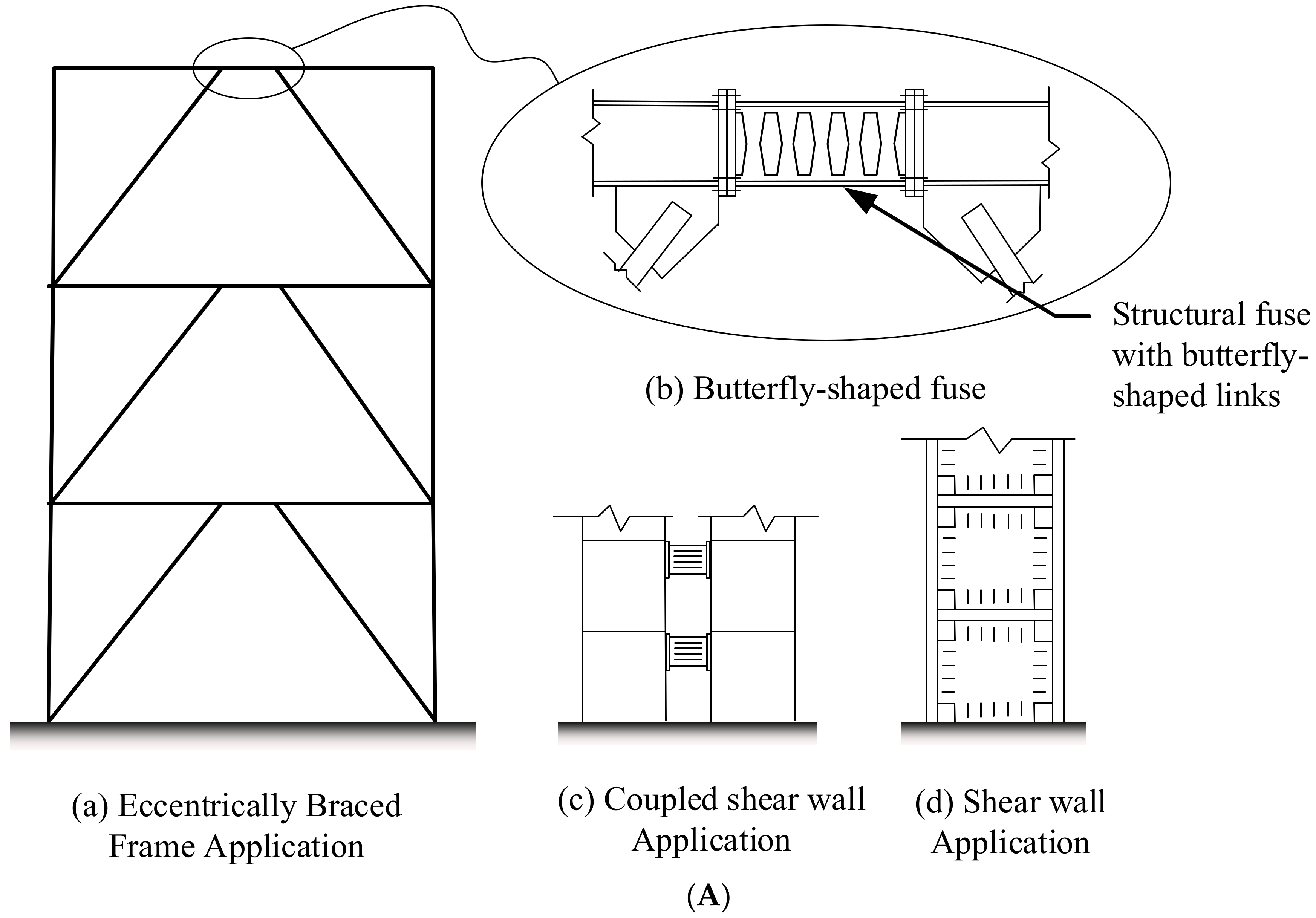
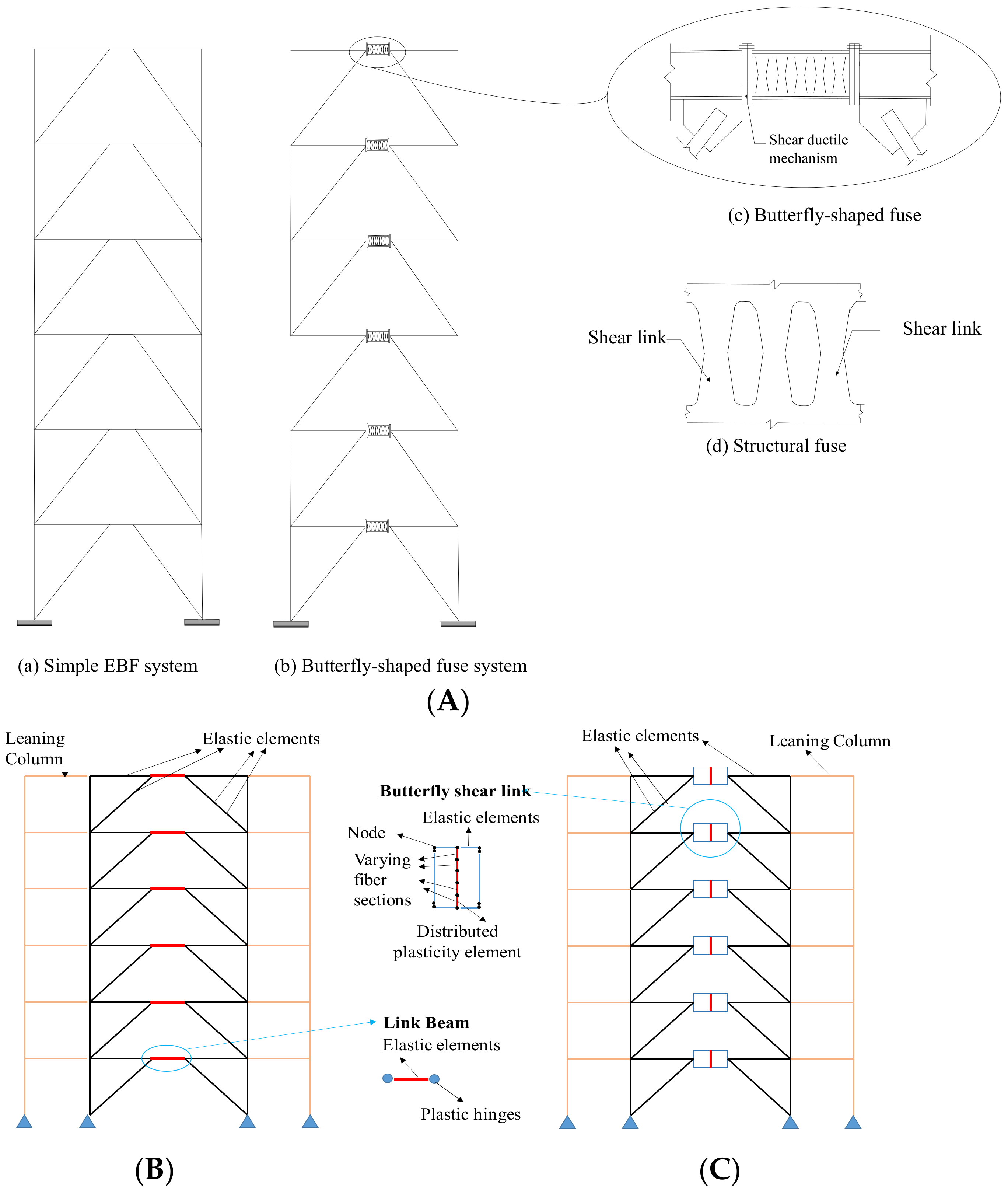
:1. Introduction
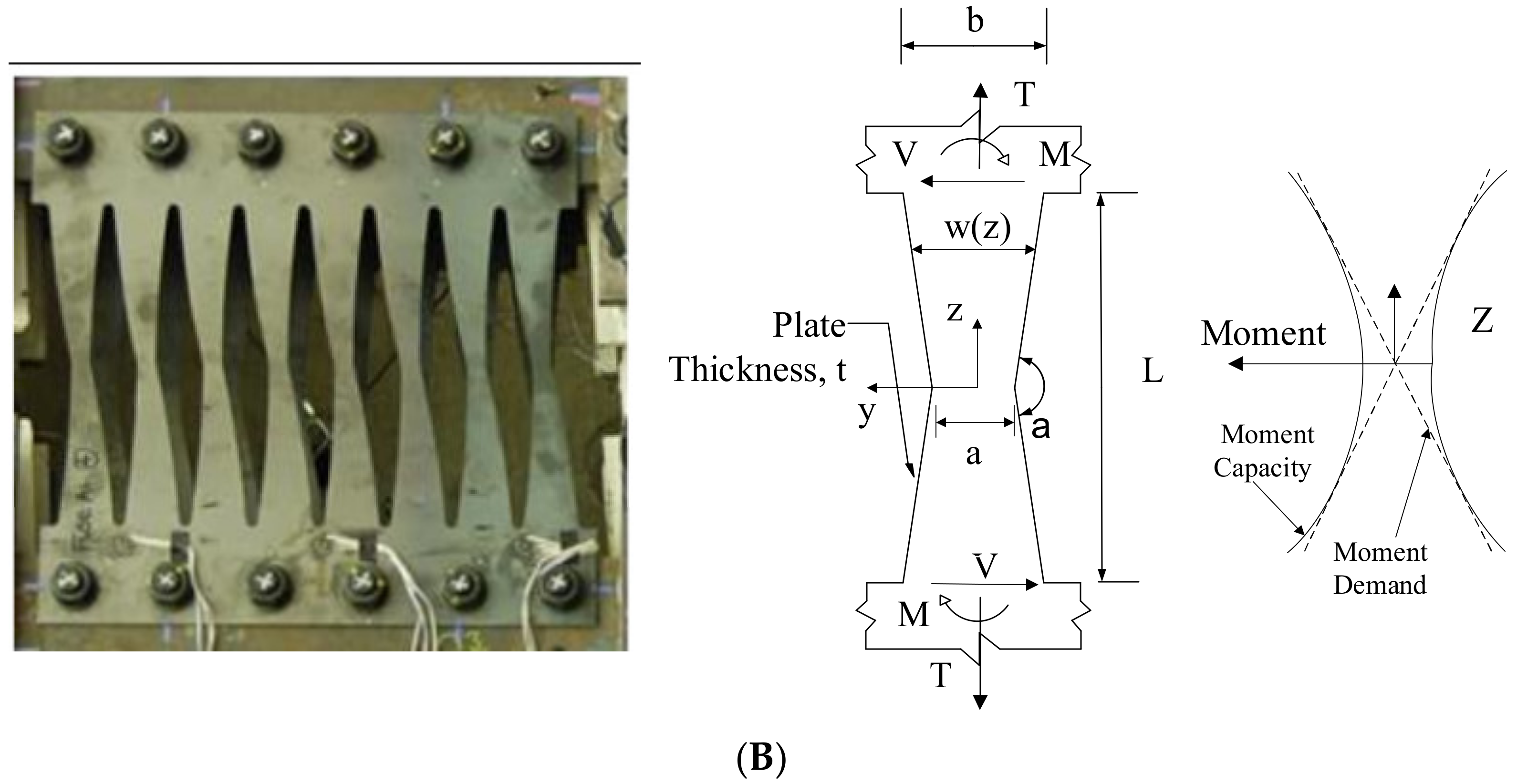
2. Guideline Design Procedures for Butterfly-Shaped Links
2.1. Limit States and Designing Requirements
2.2. Brittle and Ductile Mode of Behavior Investigations
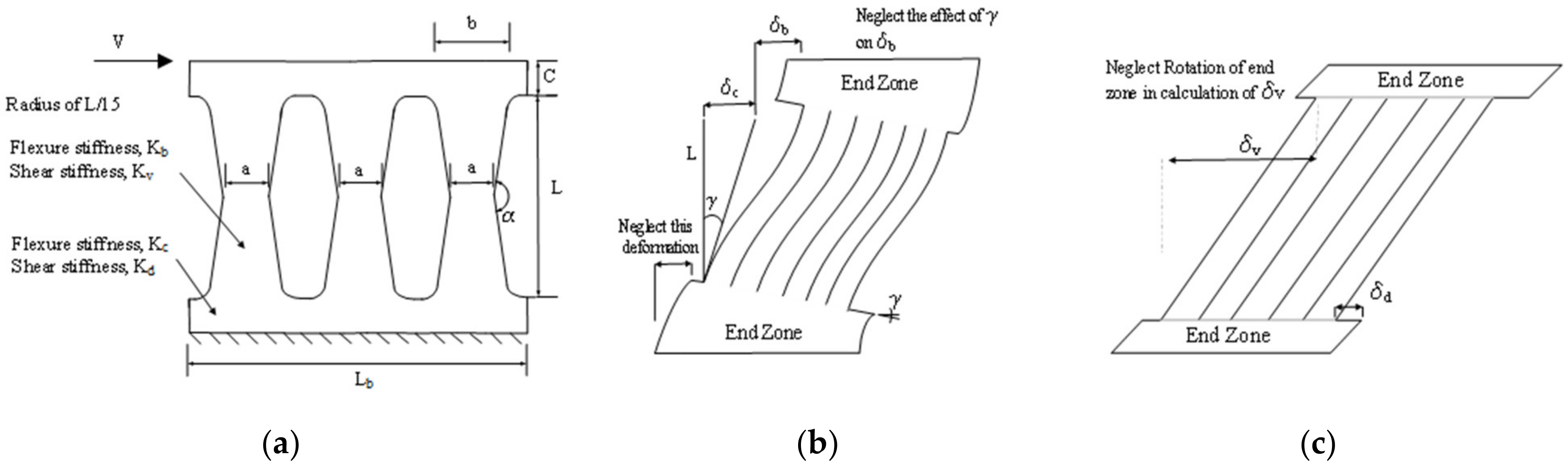
2.3. Drift Ratio Control Requirement, Based on the Stiffness
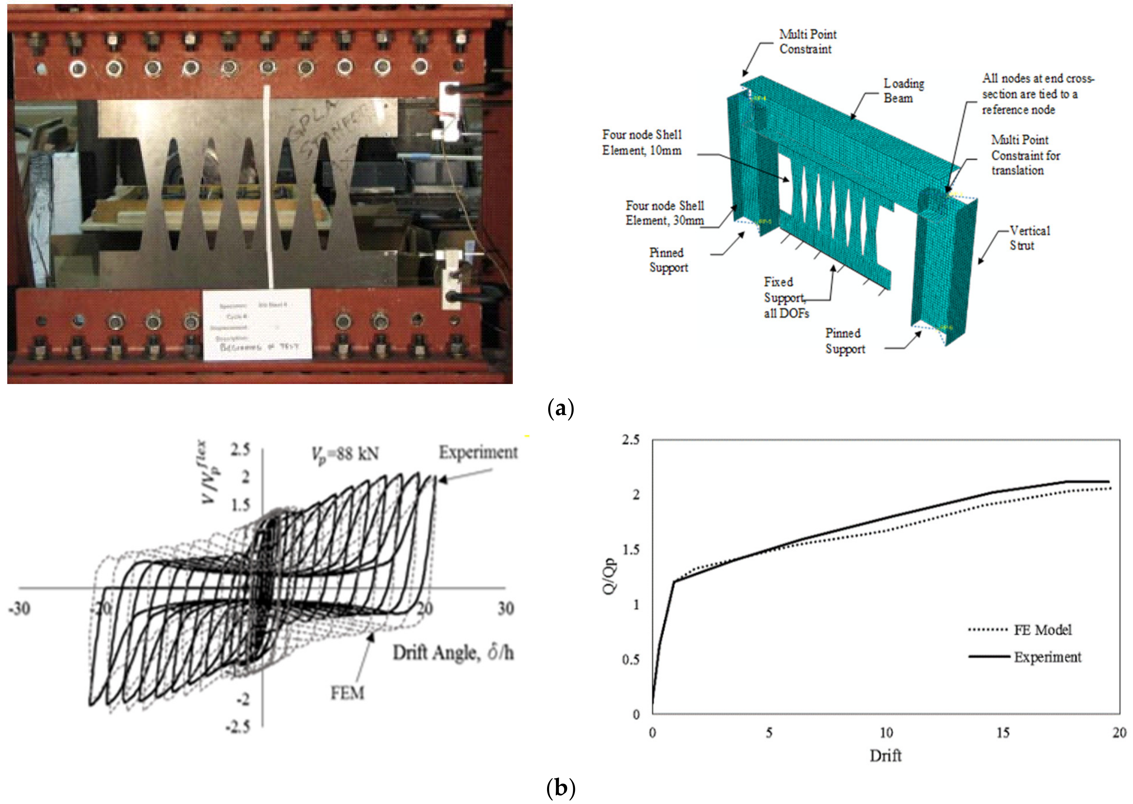
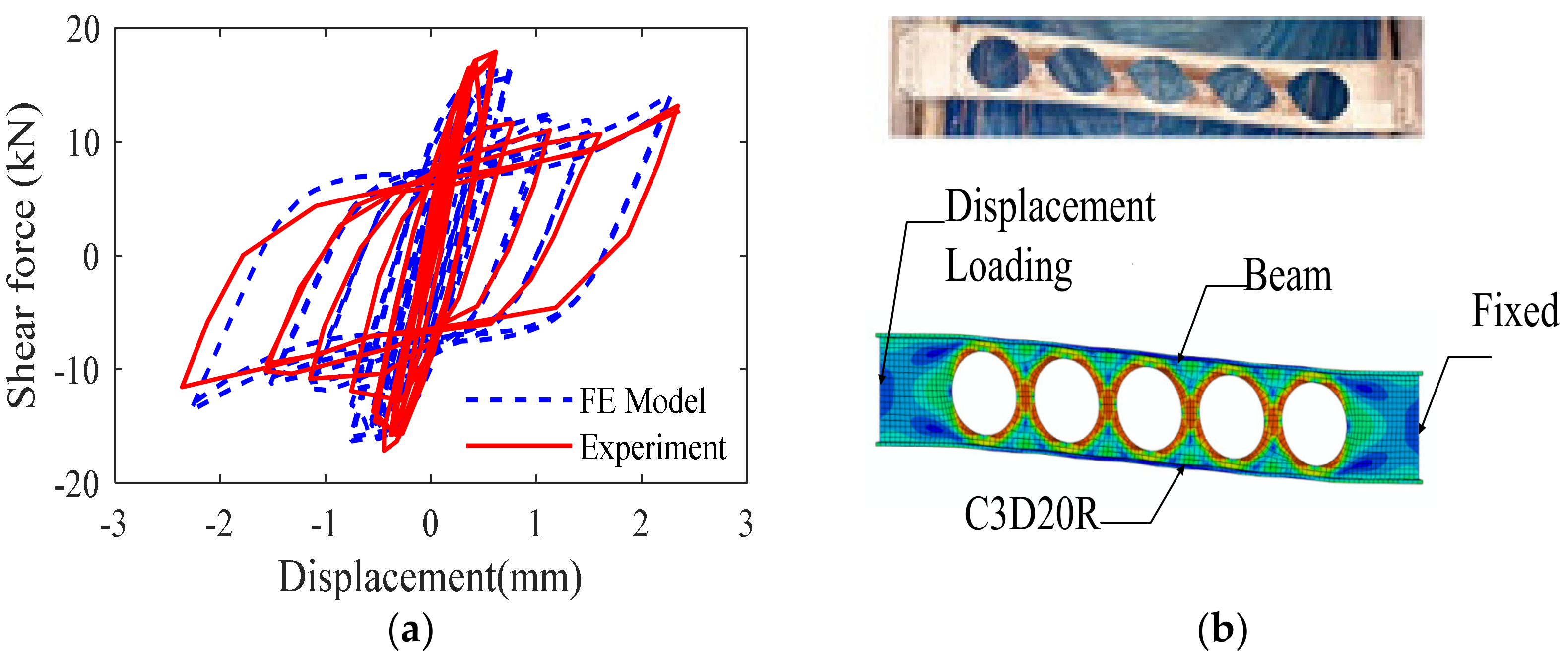
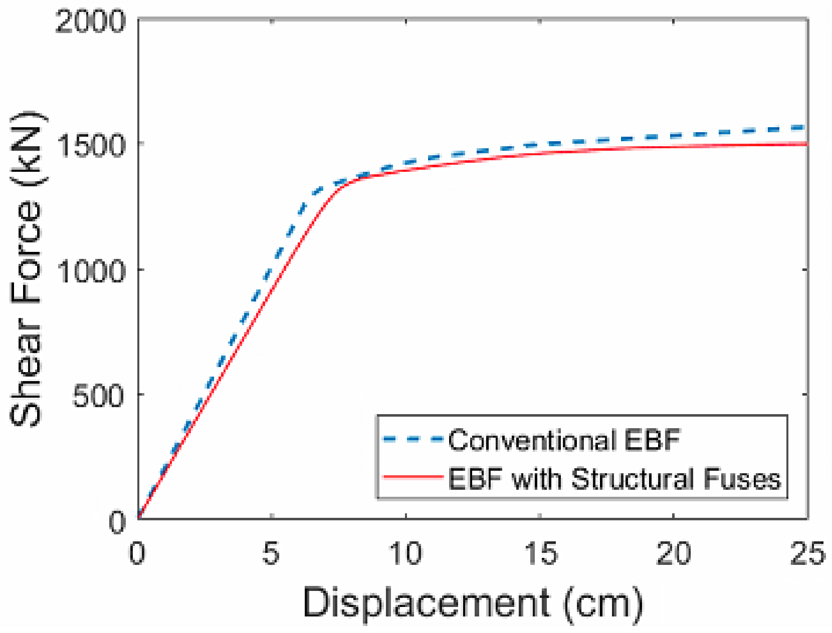
3. Verification of Finite Element Modeling Methodology via Laboratory Testing
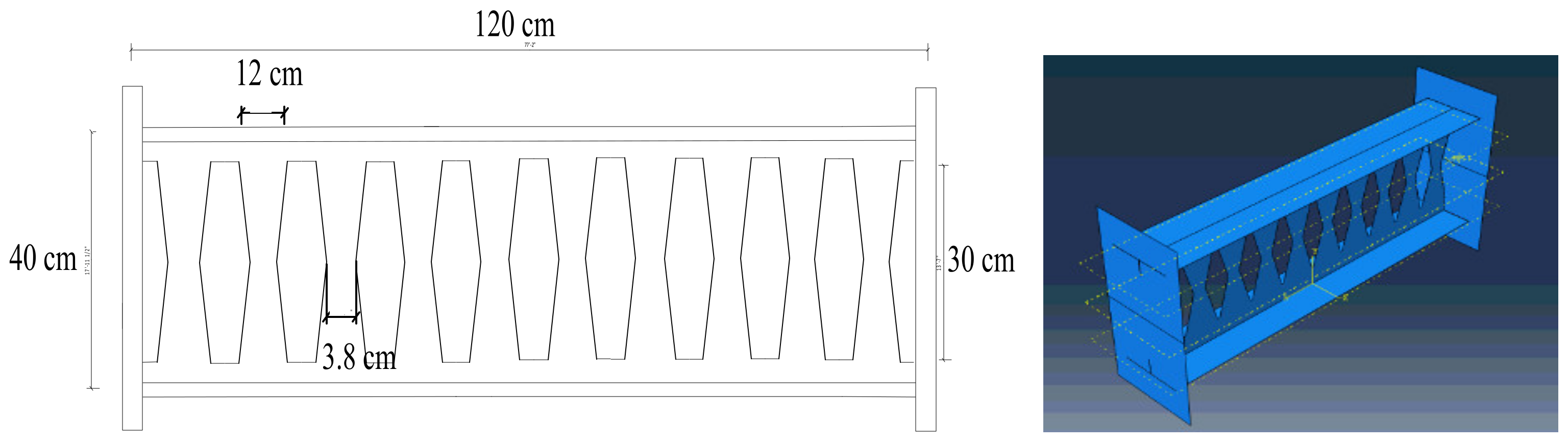
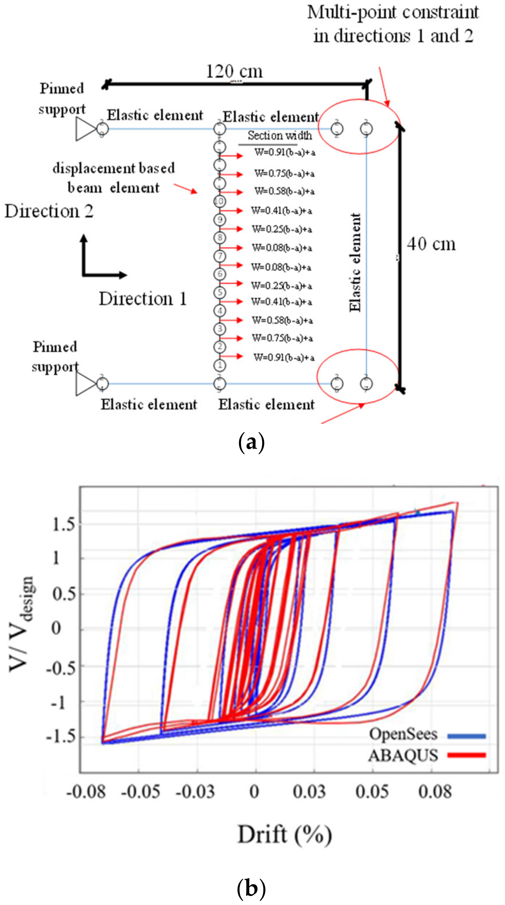
4. Preparation of Reduced-Order Simulation Models for Innovative Lateral Resisting Systems
5. Performance of Multi-Story Prototype Structure Designed Based on the Guidelines
6. Conclusions
Author Contributions
Funding
Institutional Review Board Statement
Informed Consent Statement
Data Availability Statement
Acknowledgments
Conflicts of Interest
References
- Farzampour, A.; Mansouri, I.; Mortazavi, S.J.; Hu, J.W. Force–Displacement Relationship of the Butterfly-Shaped Beams Based on Gene Expression Programming. Int. J. Steel Struct. 2020, 20, 2009–2019. [Google Scholar] [CrossRef]
- Mansouri, I.; Safa, M.; Ibrahim, Z.; Kisi, O.; Tahir, M.M.; Baharom, S.; Azimi, M. Strength Prediction of Rotary Brace Damper Using MLR and MARS. Struct. Eng. Mech. 2016, 60, 471–488. [Google Scholar] [CrossRef]
- Lee, C.H.; Kim, J.; Kim, D.H.; Ryu, J.; Ju, Y.K. Numerical and Experimental Analysis of Combined Behavior of Shear-Type Friction Damper and Non-Uniform Strip Damper for Multi-Level Seismic Protection. Eng. Struct. 2016, 114, 75–92. [Google Scholar] [CrossRef]
- Luth, G.P.; Sargunuraj, S.; Gregory, P.E.; Krawinkler, H.; Mcdonald, B. USC School of Cinema: An Example of Reparable Performance Based Design. Available online: gregorypluth.com (accessed on 1 January 2018).
- Farzampour, A.; Yekrangnia, M. On the Behavior of Corrugated Steel Shear Walls with and without Openings. In Proceedings of the Second European Conference on Earthquake Engineering and Seismology, Istanbul, Turkey, 25–29 August 2014. [Google Scholar]
- Mansouri, I.; Farzampour, A. Buckling Assessment of Imperfect Cylindrical Shells under Axial Loads Using a Gep Technique. Electron. J. Fac. Civ. Eng. Osijek-E-GFOS 2018, 9, 89–100. [Google Scholar] [CrossRef]
- Farzampour, A.; Mansouri, I.; Hu, J.W. Seismic behavior investigation of the corrugated steel shear walls considering variations of corrugation geometrical characteristics. Int. J. Steel Struct. 2018, 18, 1297–1305. [Google Scholar] [CrossRef]
- Paslar, N.; Farzampour, A.; Hatami, F. Infill Plate Interconnection Effects on the Structural Behavior of Steel Plate Shear Walls. Thin-Walled Struct. 2020, 149, 106621. [Google Scholar] [CrossRef]
- Giannuzzi, D.; Ballarini, R.; Huckelbridge, A., Jr.; Pollino, M.; Valente, M. Braced Ductile Shear Panel: New Seismic-Resistant Framing System. J. Struct. Eng. 2014, 140, 04013050. [Google Scholar] [CrossRef] [Green Version]
- Farzampour, A.; Khatibinia, M.; Mansouri, I. Shape optimization of butterfly-shaped shear links using grey wolf algorithm. Ing. Sismica 2019, 36, 27–41. [Google Scholar]
- Lim, W.Y.; Kim, S. Experimental Assessment of Seismic Vulnerability of Precast Concrete Beam-to-Beam Connections with Steel Slit Damper. Int. J. Steel Struct. 2017, 17, 1249–1260. [Google Scholar] [CrossRef]
- Farzampour, A.; Eatherton, M. Investigating Limit States for Butterfly-Shaped and Straight Shear Links. In Proceedings of the 16th European Conference on Earthquake Engineering, 16ECEE, Thessaloniki, Greece, 18–21 June 2018. [Google Scholar]
- Farzampour, A.; Eatherton, M. Parametric Study on Butterfly-Shaped Shear Links with Various Geometries. In Proceedings of the 11th National Conference on Earthquake Engineering 2018, NCEE 2018: Integrating Science, Engineering, and Policy, Los Angeles, CA, USA, 25–29 June 2018; Volume 4. [Google Scholar]
- Zeynali, K.; Saeed Monir, H.; Mirzai, N.M.; Hu, J.W. Experimental and Numerical Investigation of Lead-Rubber Dampers in Chevron Concentrically Braced Frames. Arch. Civ. Mech. Eng. 2018, 18, 162–178. [Google Scholar] [CrossRef]
- Farzampour, A.; Laman, J.A.; Mofid, M. Behavior prediction of corrugated steel plate shear walls with openings. J. Constr. Steel Res. 2015, 114, 258–268. [Google Scholar] [CrossRef]
- Paslar, N.; Farzampour, A.; Hatami, F. Investigation of the infill plate boundary condition effects on the overall performance of the steel plate shear walls with circular openings. Structures 2020, 27, 824–836. [Google Scholar] [CrossRef]
- Farzampour, A.; Mansouri, I.; Hu, J.W. Investigation of Seismic Behavior of Corrugated Steel Shear Walls Considering Variations of Corrugation Geometrical Characteristics. In Proceedings of the 9th International Symposium on Steel Structures, Jeju, Republic of Korea, 1–4 November 2017. [Google Scholar]
- Mansouri, E.; Manfredi, M.; Hu, J.W. Environmentally Friendly Concrete Compressive Strength Prediction Using Hybrid Machine Learning. Sustainability 2022, 14, 12990. [Google Scholar] [CrossRef]
- Paslar, N.; Farzampour, A. Effects of Infill Plate’s Interconnection and Boundary Element Stiffness on Steel Plate Shear Walls’ Seismic Performance. Materials 2022, 15, 5487. [Google Scholar] [CrossRef] [PubMed]
- Tsai, K.-C.; Chen, H.-W.; Hong, C.-P.; Su, Y.-F. Design of Steel Triangular Plate Energy Absorbers for Seismic-Resistant Construction. Earthq. Spectra 1993, 9, 505–528. [Google Scholar] [CrossRef]
- Farzampour, A. Structural behavior prediction of the Butterfly-shaped and straight shear fuses. Structures 2021, 33, 3964–3972. [Google Scholar] [CrossRef]
- Farzampour, A.; Eatherton, M.R. Yielding and Lateral Torsional Buckling Limit States for Butterfly-Shaped Shear Links. Eng. Struct. 2019, 180, 442–451. [Google Scholar] [CrossRef]
- Valente, M.; Castiglioni, C.A.; Kanyilmaz, A. Welded fuses for dissipative beam-to-column connections of composite steel frames: Numerical analyses. J. Constr. Steel Res. 2017, 128, 498–511. [Google Scholar] [CrossRef]
- Cao, X.Y.; Shen, D.; Feng, D.C.; Li, Y. Assessment of various seismic fragility analysis approaches for structures excited by non-stationary stochastic ground motions. Mech. Syst. Signal Process. 2023, 186, 109838. [Google Scholar] [CrossRef]
- Farzampour, A.; Eatherton, M.R. Parametric Computational Study on Butterfly-Shaped Hysteretic Dampers. Front. Struct. Civ. Eng. 2019, 13, 1214–1226. [Google Scholar] [CrossRef]
- Farzampour, A. Evaluating Shear Links for Use in Seismic Structural Fuses. Ph.D. Thesis, Virginia Tech, Blacksburg, VA, USA, 2019. [Google Scholar]
- Farzampour, A.; Mortazavi, S.J.; Mansouri, I.; Awoyera, P.O.; Hu, J.W. Multistory buildings equipped with innovative structural seismic shear fuse systems. In Seismic Evaluation, Damage, and Mitigation in Structures; Woodhead Publishing: Sawston, UK, 2023. [Google Scholar] [CrossRef]
- Farzampour, A.; Mansouri, I.; Dehghani, H. Incremental Dynamic Analysis for Estimating Seismic Performance of Multi-Story Buildings with Butterfly-Shaped Structural Dampers. Buildings 2019, 9, 78. [Google Scholar] [CrossRef] [Green Version]
- Farzampour, A.; Mansouri, I.; Lee, C.H.; Sim, H.B.; Hu, J.W. Analysis and Design Recommendations for Corrugated Steel Plate Shear Walls with a Reduced Beam Section. Thin-Walled Struct. 2018, 132, 658–666. [Google Scholar] [CrossRef]
- Farzampour, A. Innovative Structural Fuse Systems for Various Prototype Applications. Materials 2022, 15, 805. [Google Scholar] [CrossRef]
- Ma, X.; Borchers, E.; Pena, A.; Krawinkler, H.; Billington, S.; Deierlein, G.G. Design and Behavior of Steel Shear Plates with Openings as Energy-Dissipating Fuses; John A. Blume Earthquake Engineering Center Technical Report; John A. Blume Earthquake Engineering Center: Stanford, CA, USA, 2010; Volume 173. [Google Scholar]
- Shin, M.; Kim, S.P.; Halterman, A.; Aschheim, M. Seismic Toughness and Failure Mechanisms of Reduced Web-Section Beams: Phase 1 Tests. Eng. Struct. 2017, 141, 198–216. [Google Scholar] [CrossRef] [Green Version]
- AISC Committee. Seismic Provision for Structural Steel Buildings (ANSI/AISC 341-16); AISC Committee: Chicago, IL, USA, 2016. [Google Scholar]
- ICC Staff; SEAOC Staff. 2012 IBC SEAOC Structural Seismic Design Manual Vol. 3: Examples for Concrete Buildings; International Code Council: San Francisco, CA, USA, 2012. [Google Scholar]


| Shear Fuse | b/L | ||
|---|---|---|---|
| a/b | 0.1 | 0.1 | 4.1 |
| 0.2 | 3.3 | ||
| 0.3 | 2.8 | ||
| 0.4 | 1.8 | ||
| 0.33 | 0.1 | 2.3 | |
| 0.2 | 1.65 | ||
| 0.3 | 1.35 | ||
| 0.4 | 1.3 | ||
| 0.75 | 0.1 | 4.13 | |
| 0.2 | 3.18 | ||
| 0.3 | 2.51 | ||
| 0.4 | 1.95 | ||
| 1 | 0.1 | 4.35 | |
| 0.2 | 3.35 | ||
| 0.3 | 2.75 | ||
| 0.4 | 2.45 | ||
| Normalized PEEQ at 5% | Mid Width (a)/End Width (b) | |||
|---|---|---|---|---|
| b/L | 0.1 | 0.33 | 0.75 | 1 |
| 0.1 | 5.82 | 2.35 | 2.59 | 5.18 |
| 0.2 | 8.41 | 6.18 | 5.47 | 15.94 |
| 0.3 | 16.35 | 1.03 | 1.00 | 16.76 |
| 0.4 | 20.71 | 1.29 | 1.24 | 21.76 |
| a/b | ||||||
|---|---|---|---|---|---|---|
| 0.1 | 0.33 | 0.66 | 1 | |||
| K shear factor | b/L | 0.2 | 0.065 | 0.100 | 0.136 | 0.2 |
| 0.4 | 0.130 | 0.201 | 0.272 | 0.4 | ||
| 0.6 | 0.195 | 0.302 | 0.409 | 0.6 | ||
| 0.8 | 0.260 | 0.402 | 0.545 | 0.8 | ||
| a/b | ||||||
|---|---|---|---|---|---|---|
| 0.1 | 0.33 | 0.66 | 1 | |||
| K flexure factor | b/L | 0.2 | 0.2 | 0.001 | 0.003 | 0.005 |
| 0.4 | 0.4 | 0.015 | 0.03 | 0.047 | ||
| 0.6 | 0.6 | 0.052 | 0.101 | 0.159 | ||
| 0.8 | 0.8 | 0.124 | 0.239 | 0.378 | ||
| Level | Shear (Kips) | Cumulative Force (kN) | Design Force for the Butterfly Links with Equation (26) (kN) | Design Groups | Specifications | |
|---|---|---|---|---|---|---|
| Roof | 60 | 267 | 1085 | 1085 | III | BU 13 × 53 |
| Six | 60 | 534 | 1085 | BU 13 × 53 | ||
| Five | 88 | 925 | 1592 | 1592 | II | BU13 × 53 |
| Four | 125 | 1481 | 2260 | 2260 | I | W 10 × 68 |
| Third | 125 | 2438 | 2260 | W 10 × 68 | ||
| Second | 125 | 2593 | 2260 | W 10 × 68 | ||
Disclaimer/Publisher’s Note: The statements, opinions and data contained in all publications are solely those of the individual author(s) and contributor(s) and not of MDPI and/or the editor(s). MDPI and/or the editor(s) disclaim responsibility for any injury to people or property resulting from any ideas, methods, instructions or products referred to in the content. |
© 2023 by the authors. Licensee MDPI, Basel, Switzerland. This article is an open access article distributed under the terms and conditions of the Creative Commons Attribution (CC BY) license (https://creativecommons.org/licenses/by/4.0/).
Share and Cite
Farzampour, A.; Mansouri, I.; Mortazavi, S.J.; Retzepis, E.; Kaloop, M.R.; Hu, J.-W. Development of Innovative Lateral Resistance Systems Featuring Earthquake-Protective Dampers. Appl. Sci. 2023, 13, 3852. https://doi.org/10.3390/app13063852
Farzampour A, Mansouri I, Mortazavi SJ, Retzepis E, Kaloop MR, Hu J-W. Development of Innovative Lateral Resistance Systems Featuring Earthquake-Protective Dampers. Applied Sciences. 2023; 13(6):3852. https://doi.org/10.3390/app13063852
Chicago/Turabian StyleFarzampour, Alireza, Iman Mansouri, Seyed Javad Mortazavi, Eleni Retzepis, Mosbeh R. Kaloop, and Jong-Wan Hu. 2023. "Development of Innovative Lateral Resistance Systems Featuring Earthquake-Protective Dampers" Applied Sciences 13, no. 6: 3852. https://doi.org/10.3390/app13063852