
A Study on Development of New Type Rubber Boot for Sleeper Floating Track System (STEDEF): Materials and Shapes

Abstract
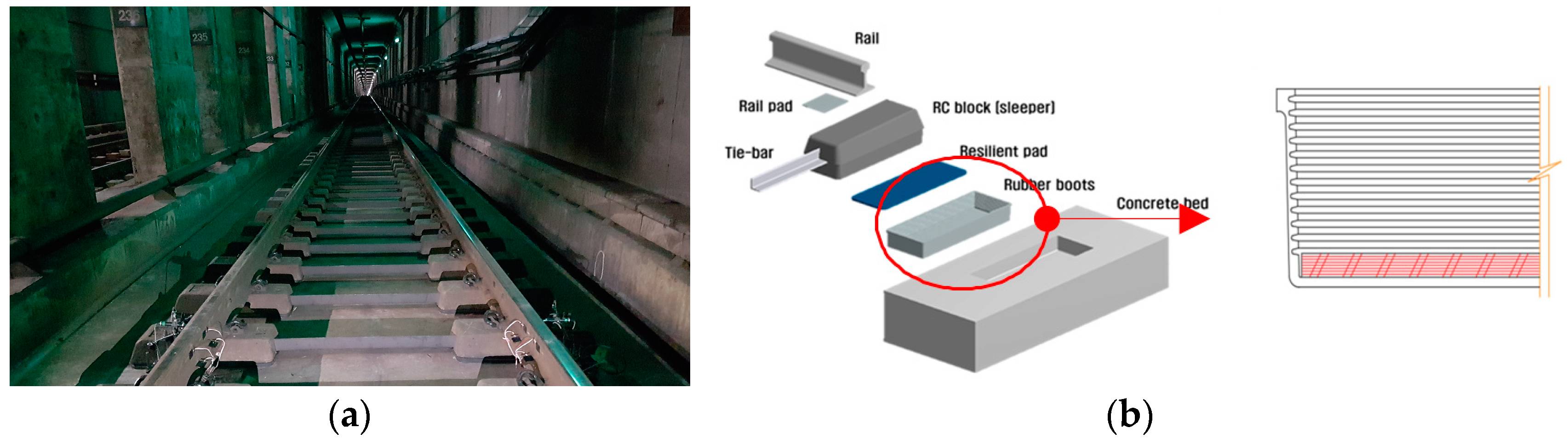
:1. Introduction
2. Numerical Analysis
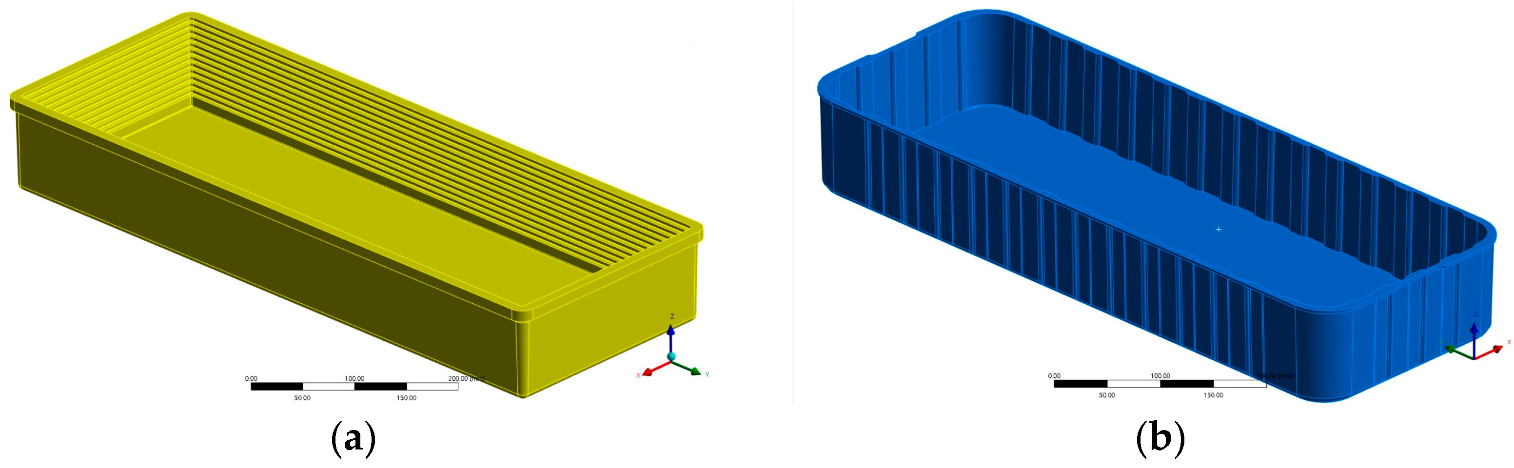
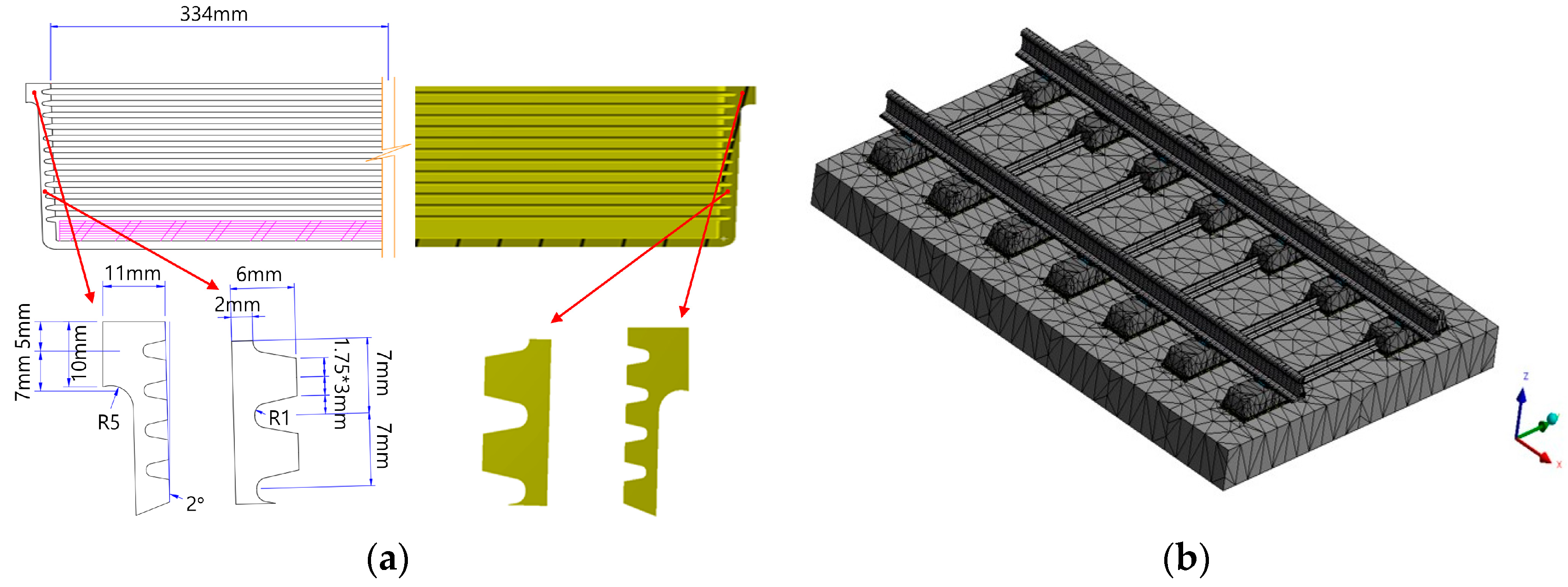
2.1. Design of Rubber Boot
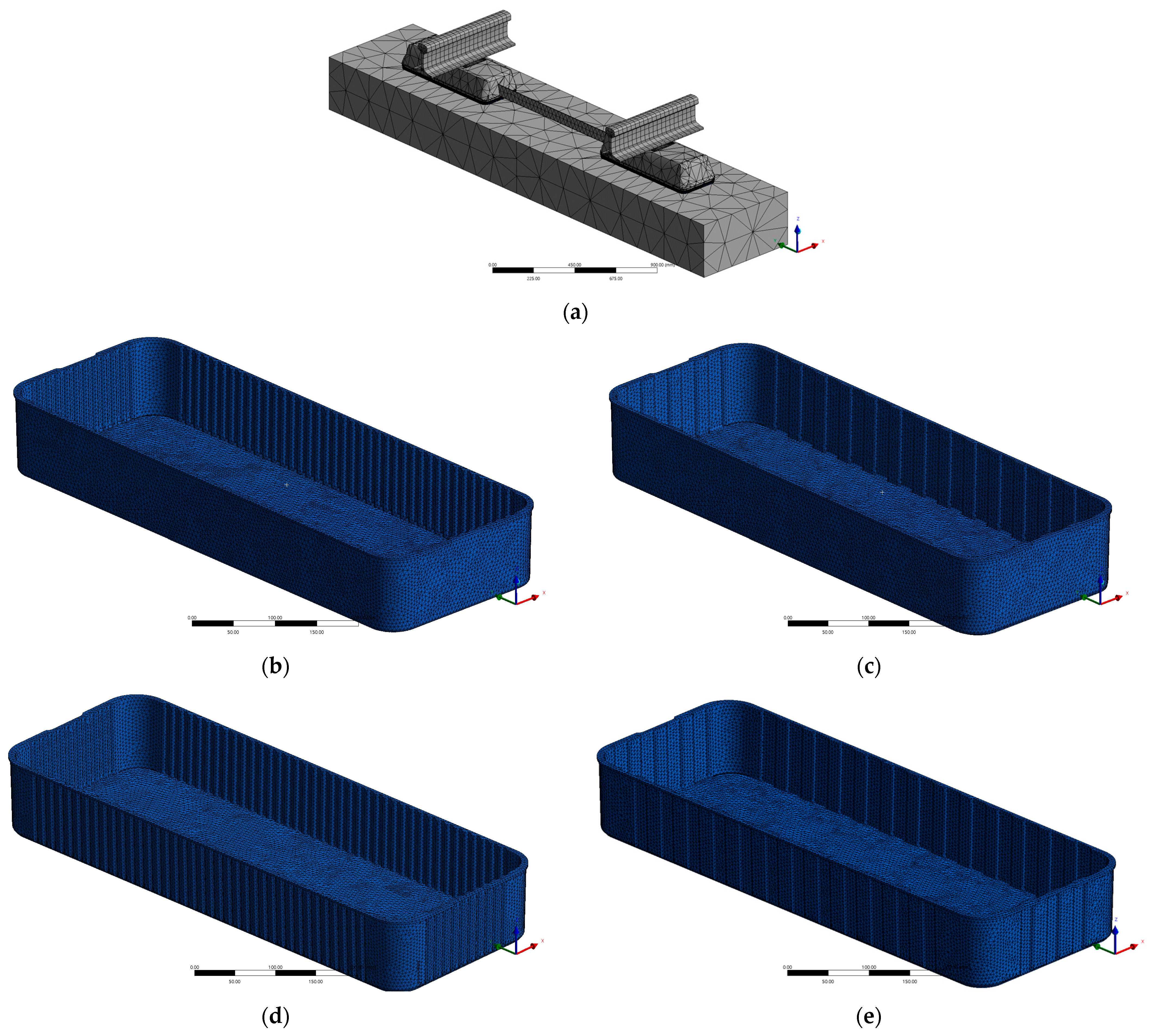
2.2. Modeling
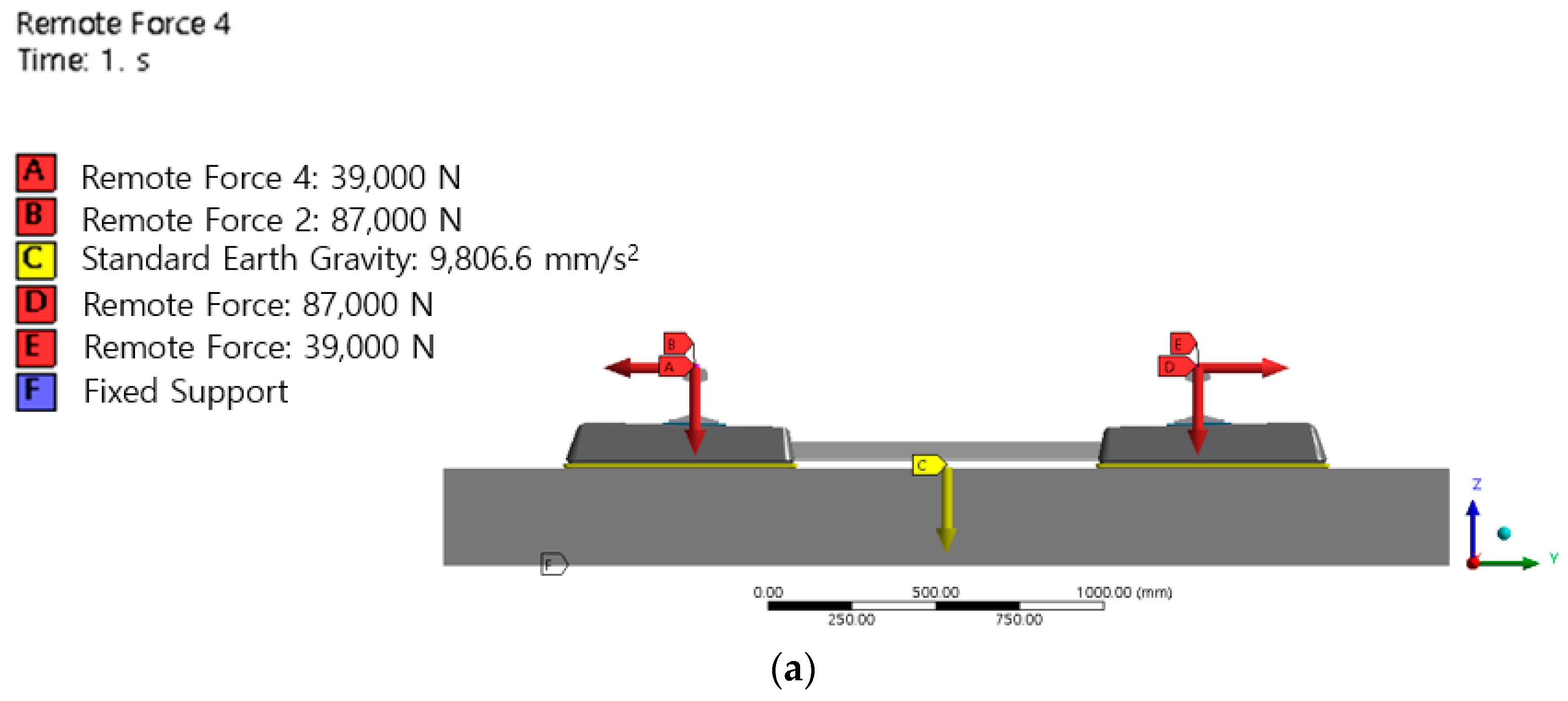
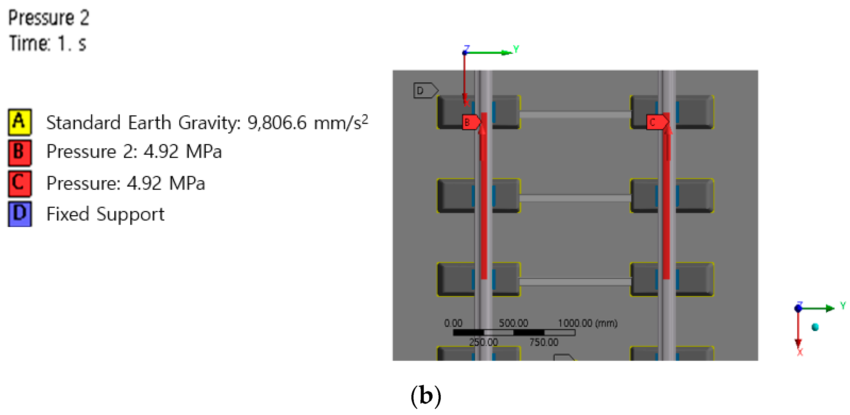
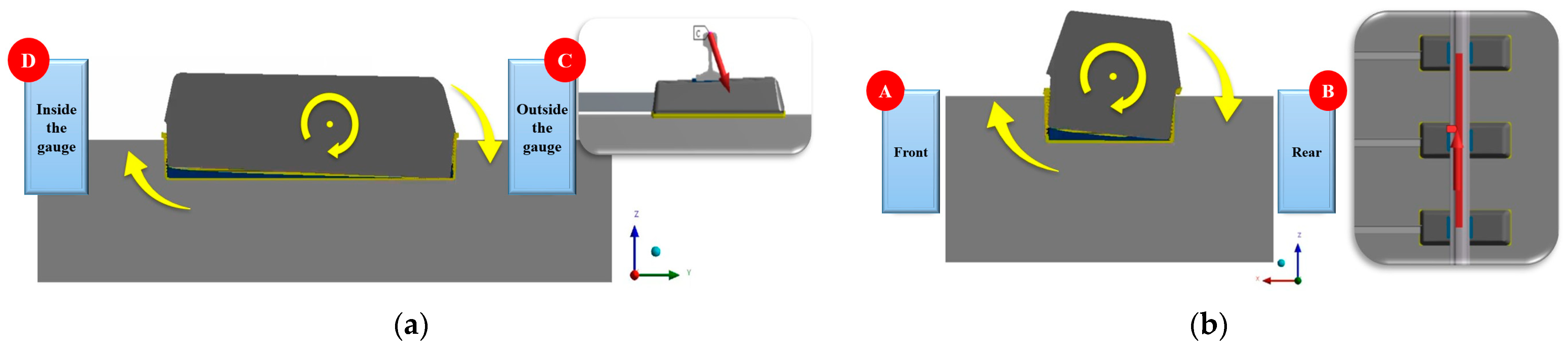
2.3. Loading and Boundary Conditions
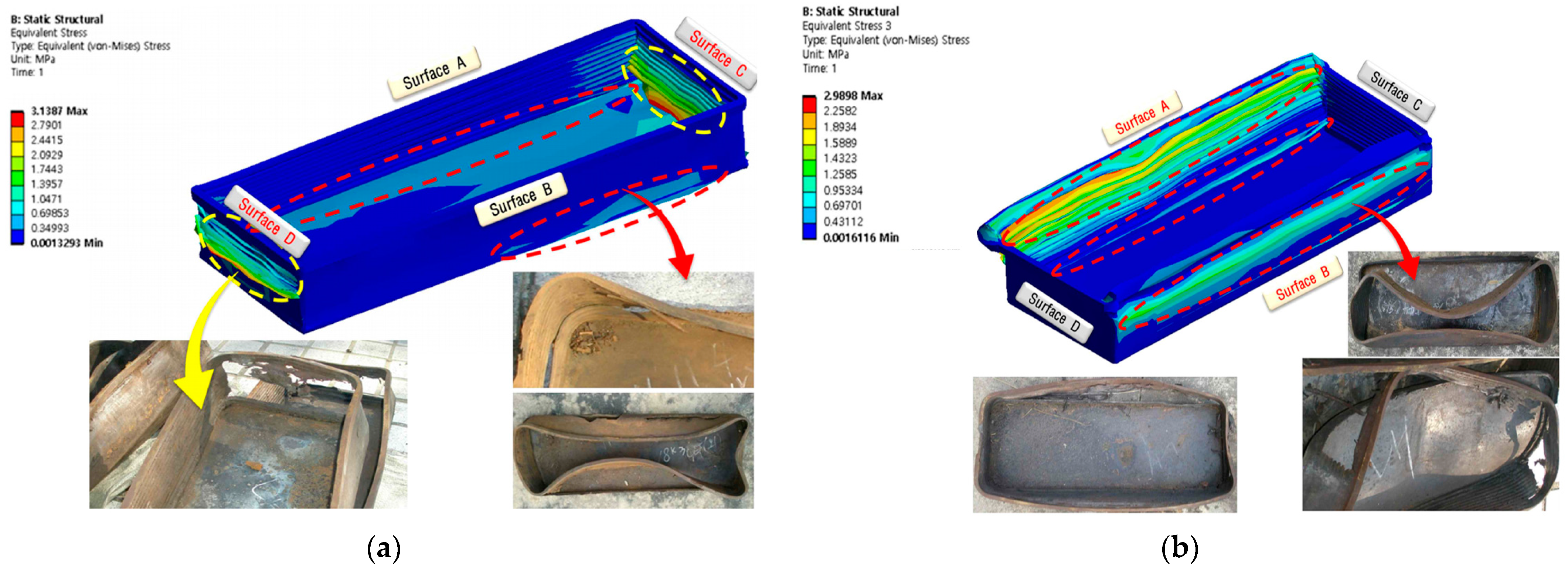
2.4. Numerical Analysis Result
- (1)
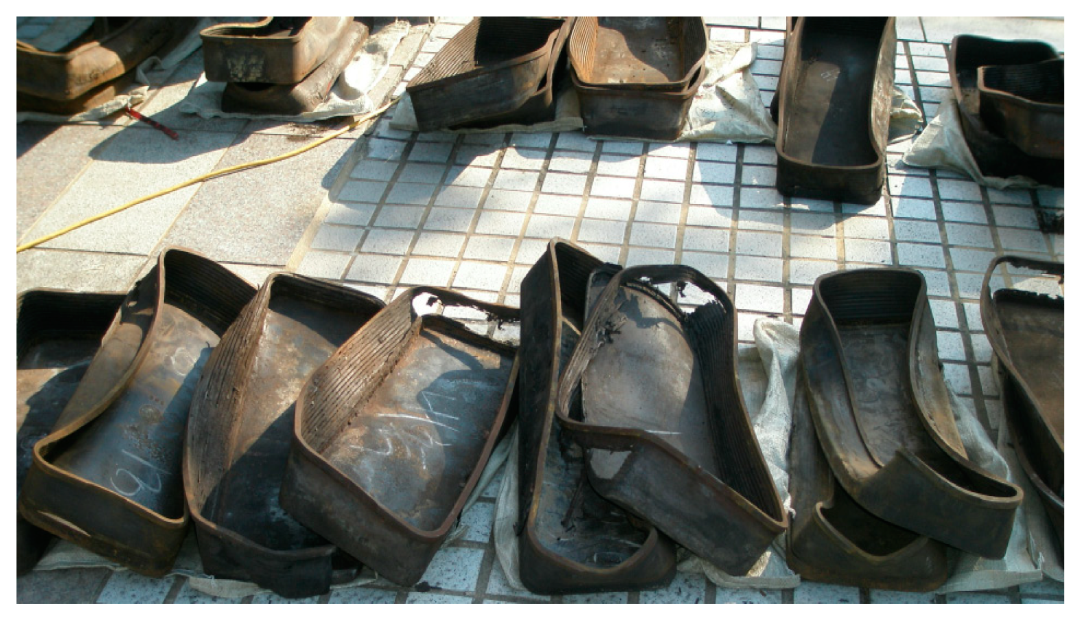
- Analysis of Rubber Boot Damage Mechanism and Cause of Damage
- (2)
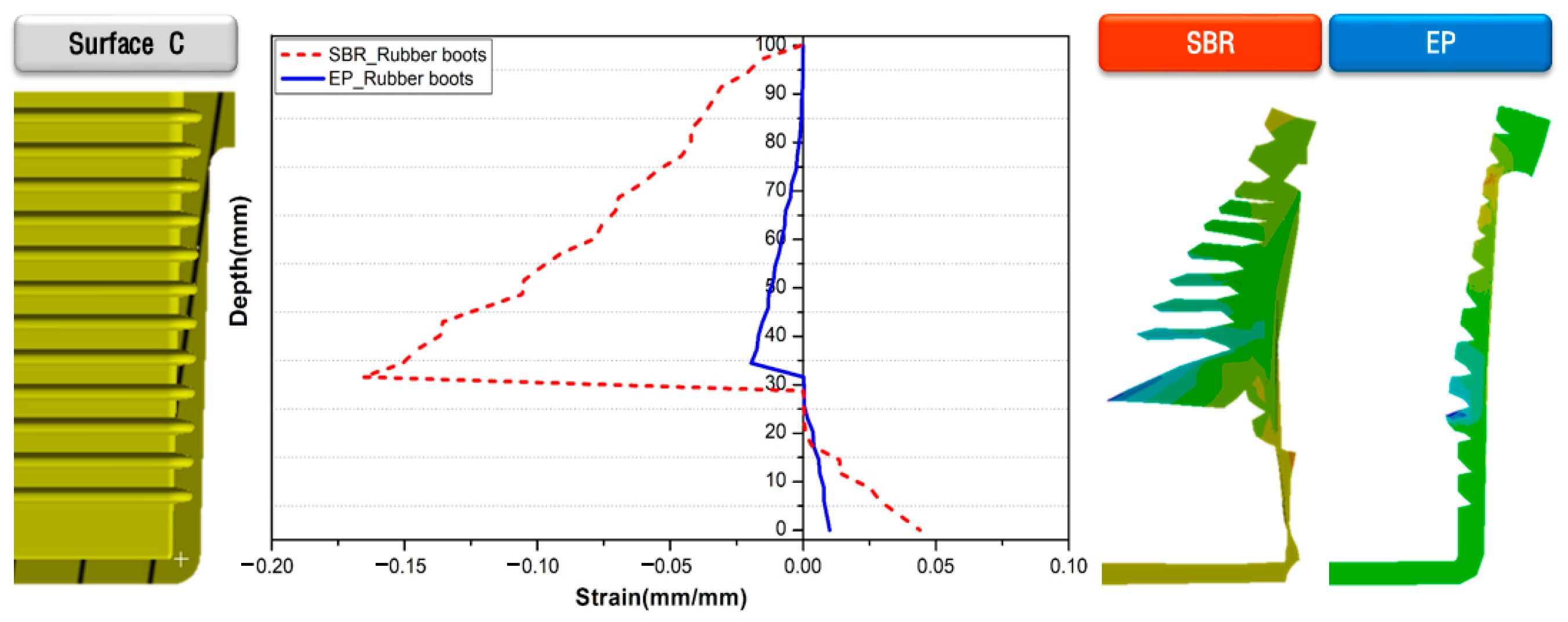
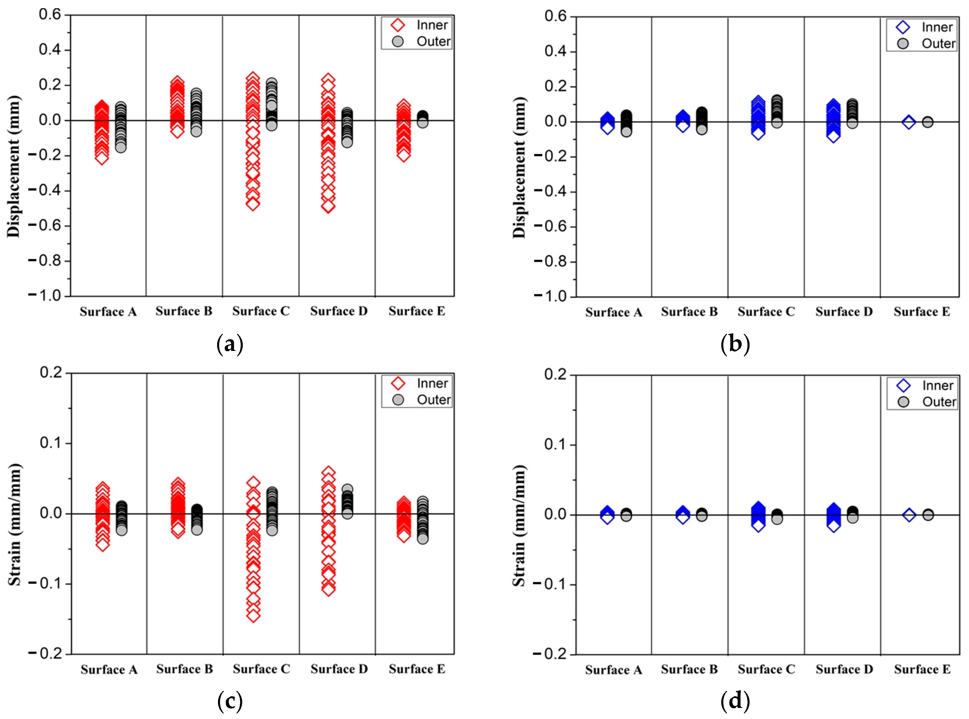
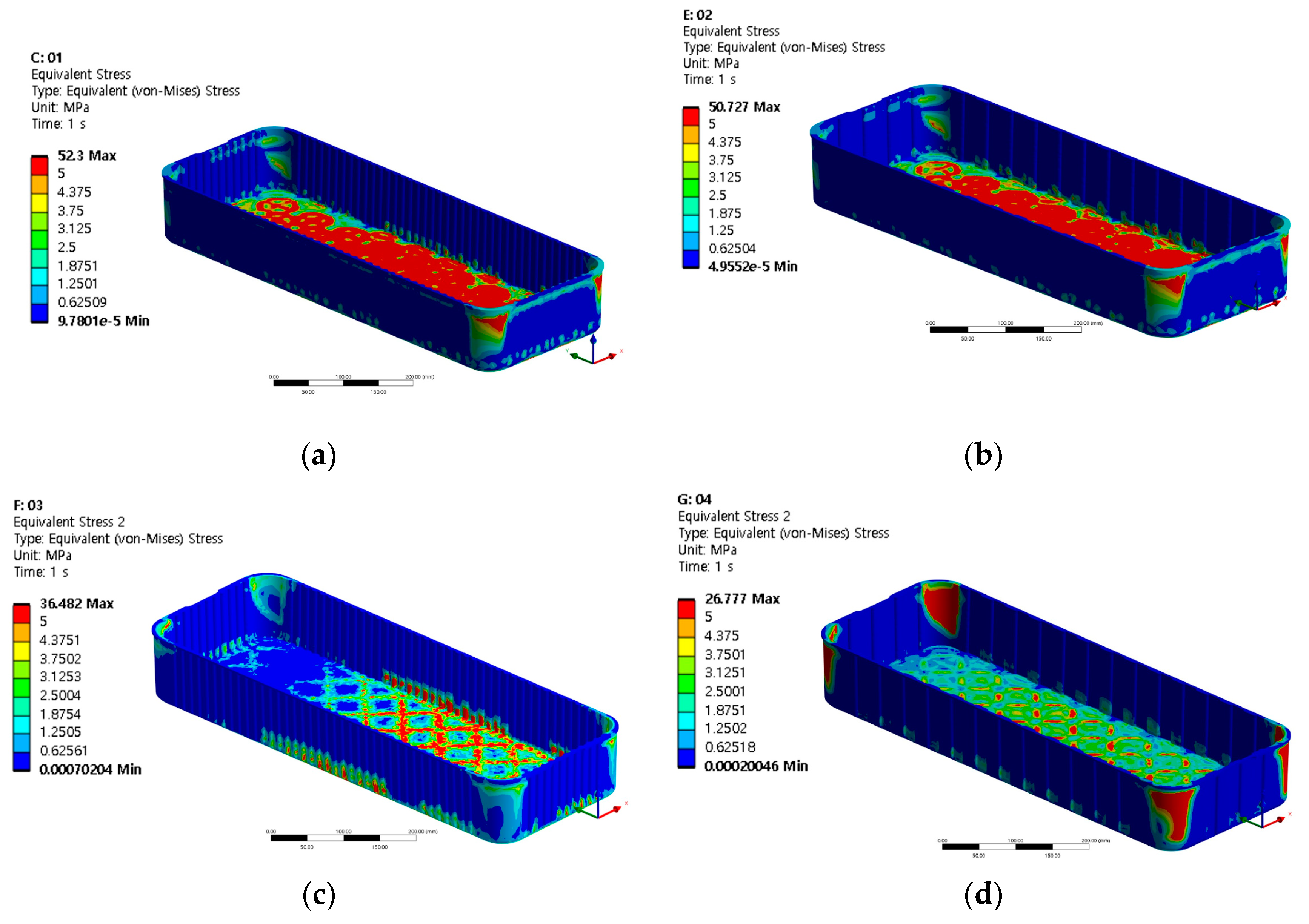
- Analysis of Rubber Boot Deformation According to Material Change
- (3)
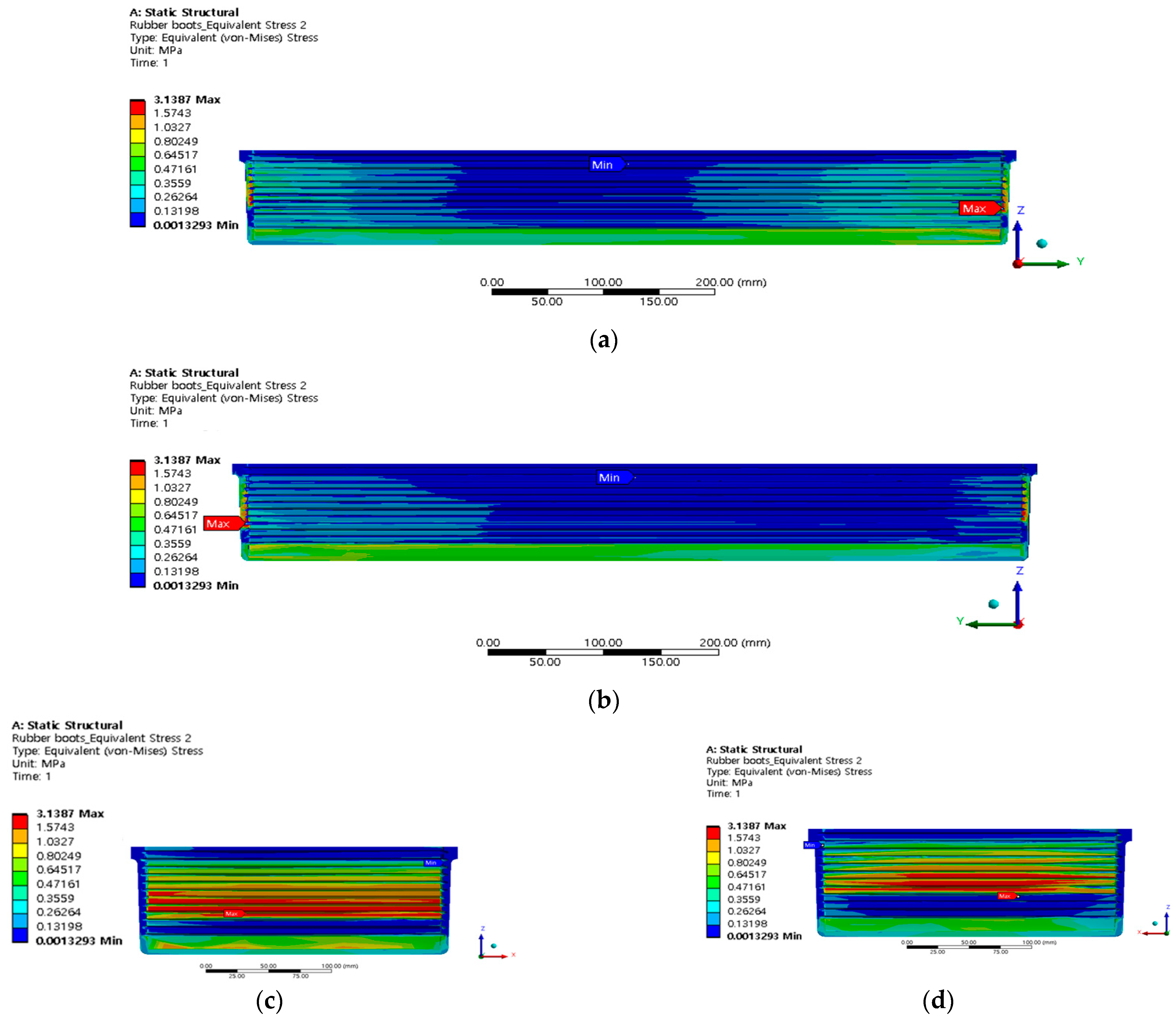
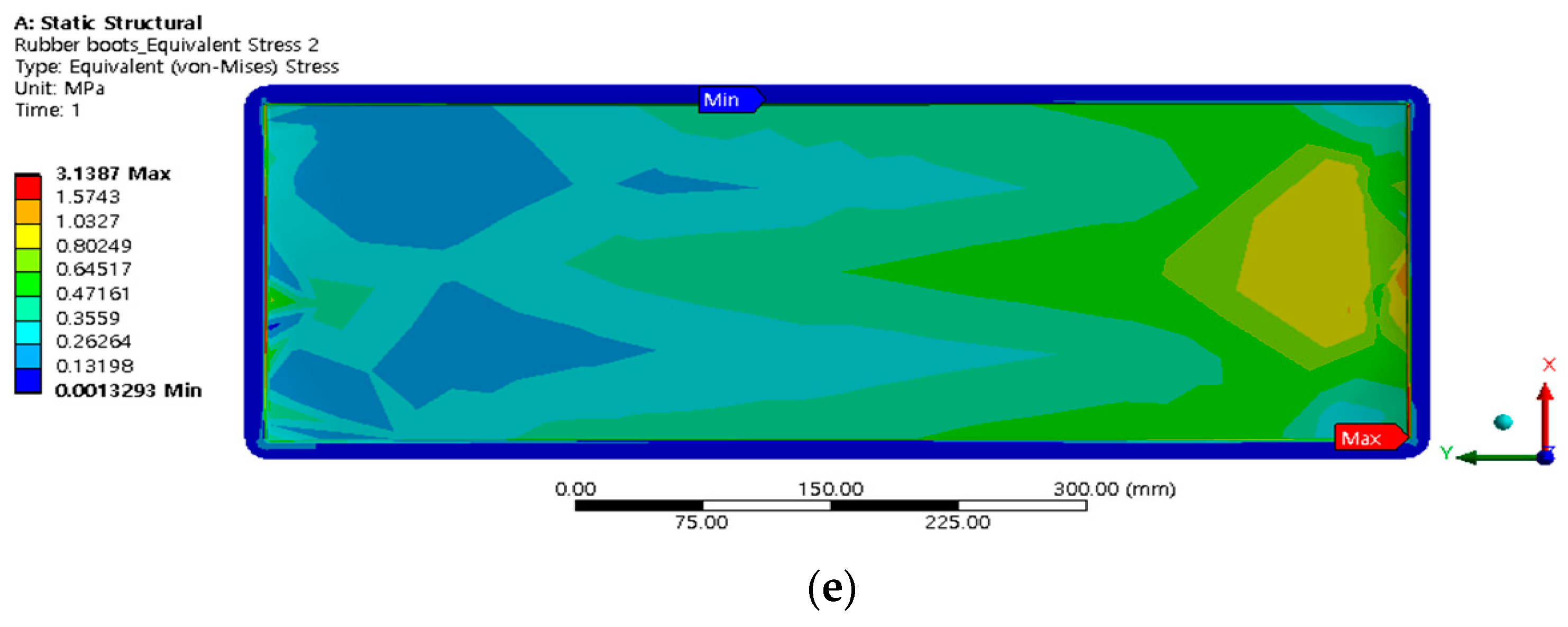
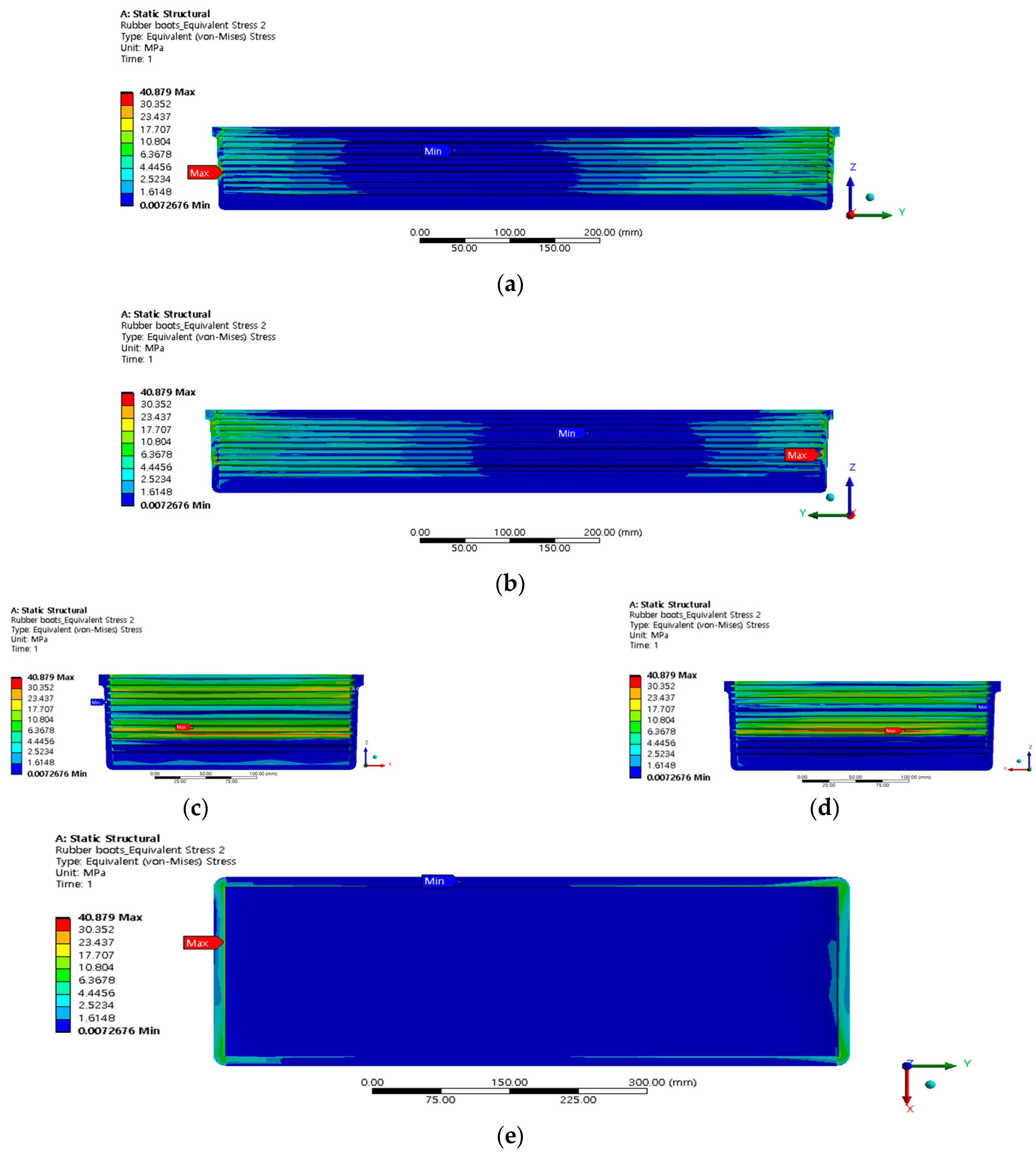
- Equivalent stress analysis of rubber boots according to material change
- (4)
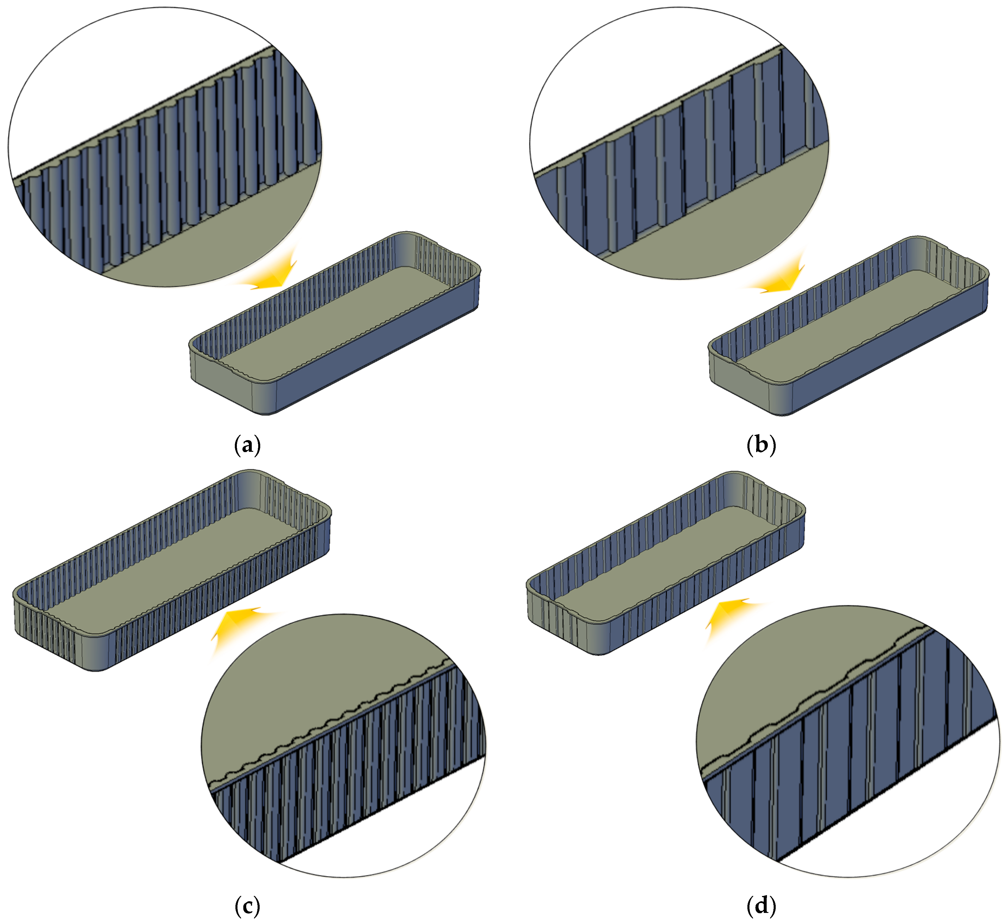
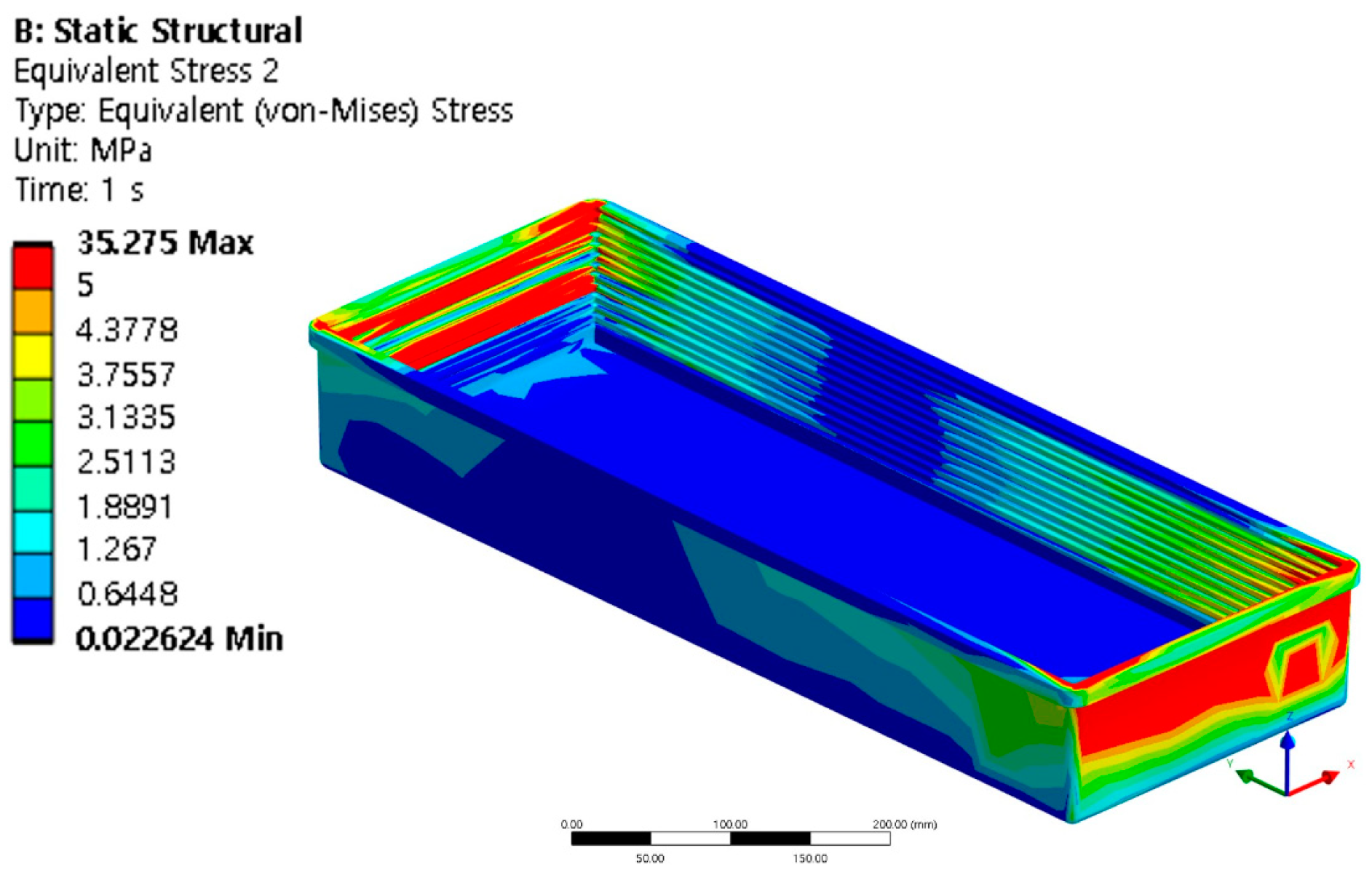
- Deformation Analysis of Rubber Boots According to Shape Change
3. Indoor Test
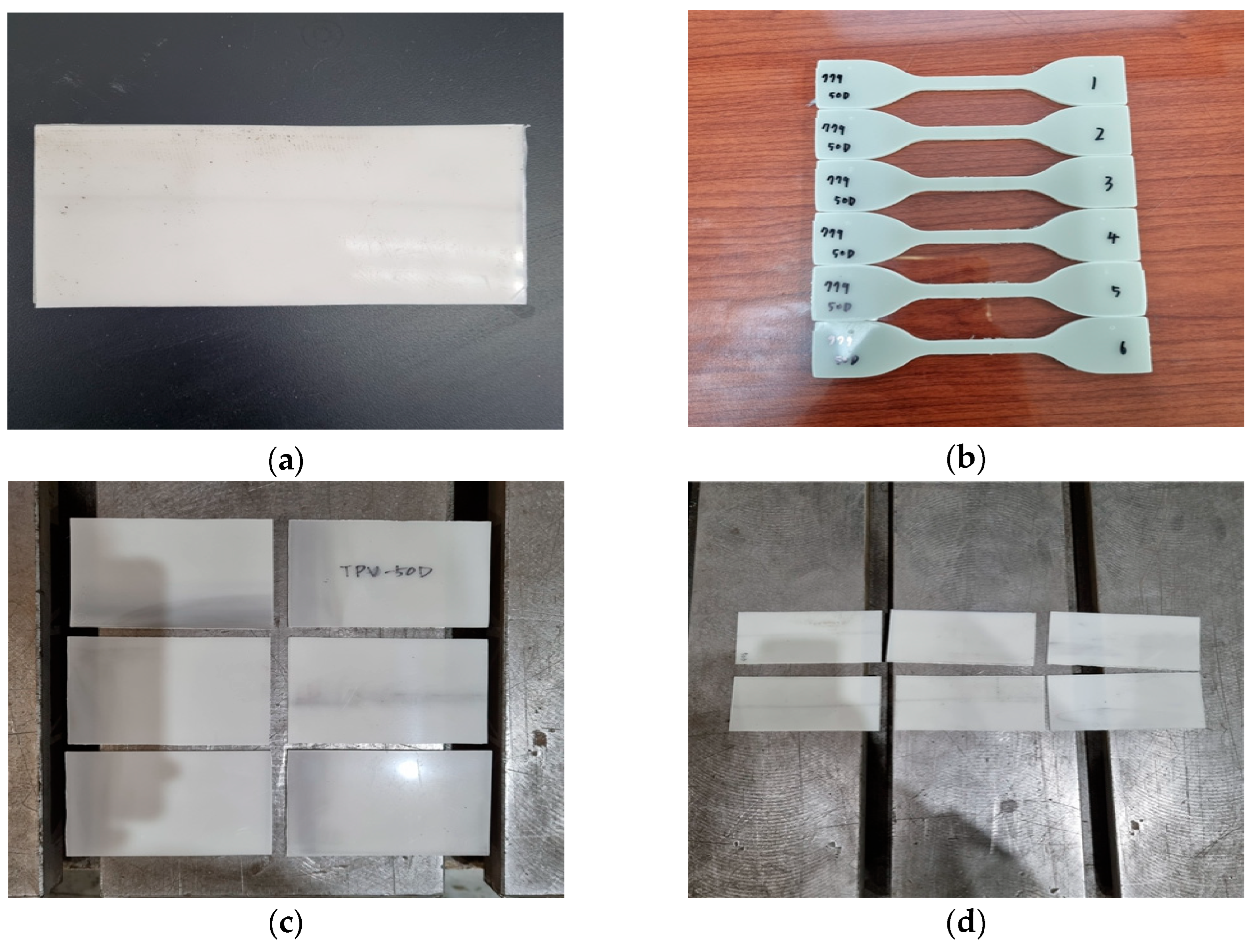
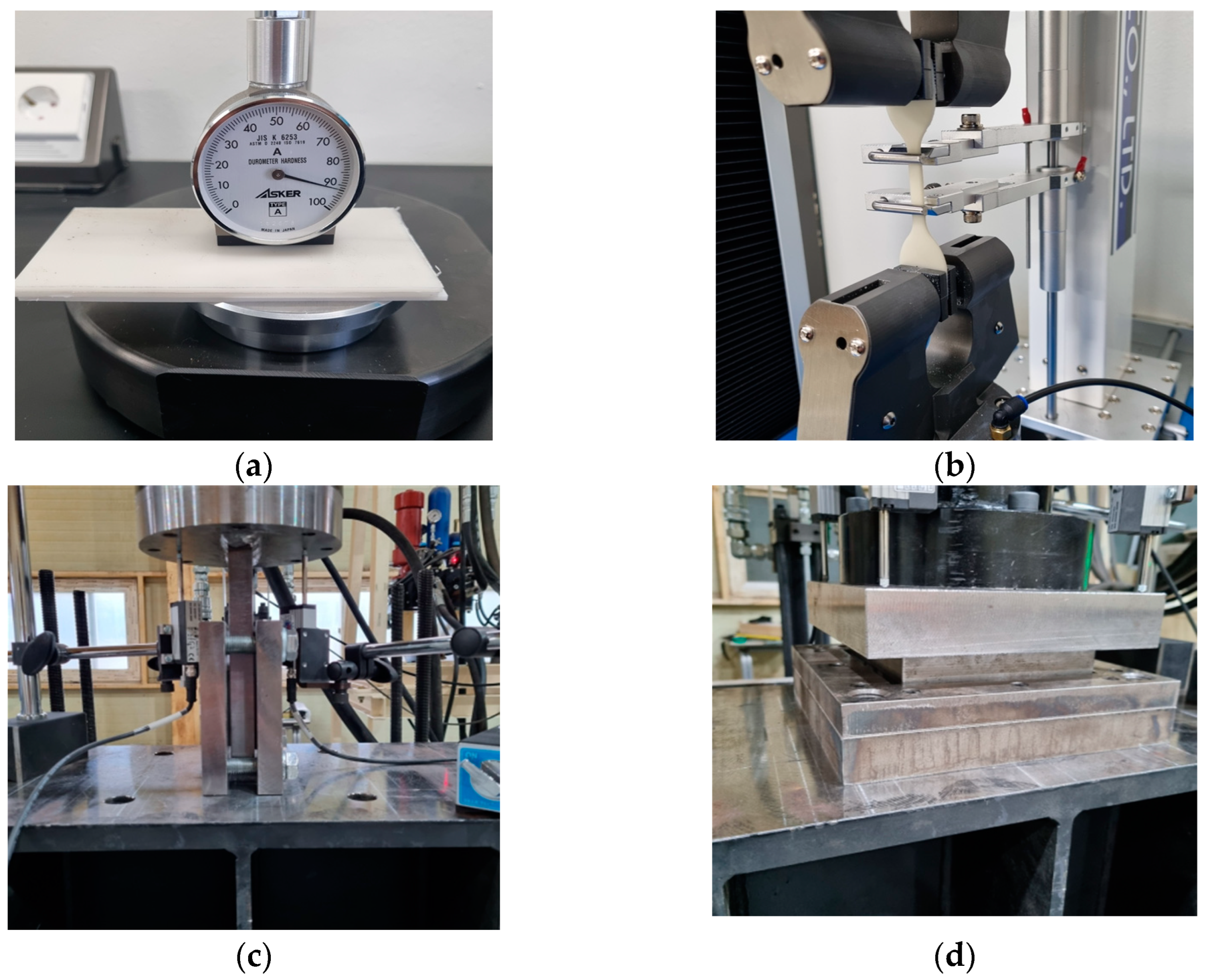
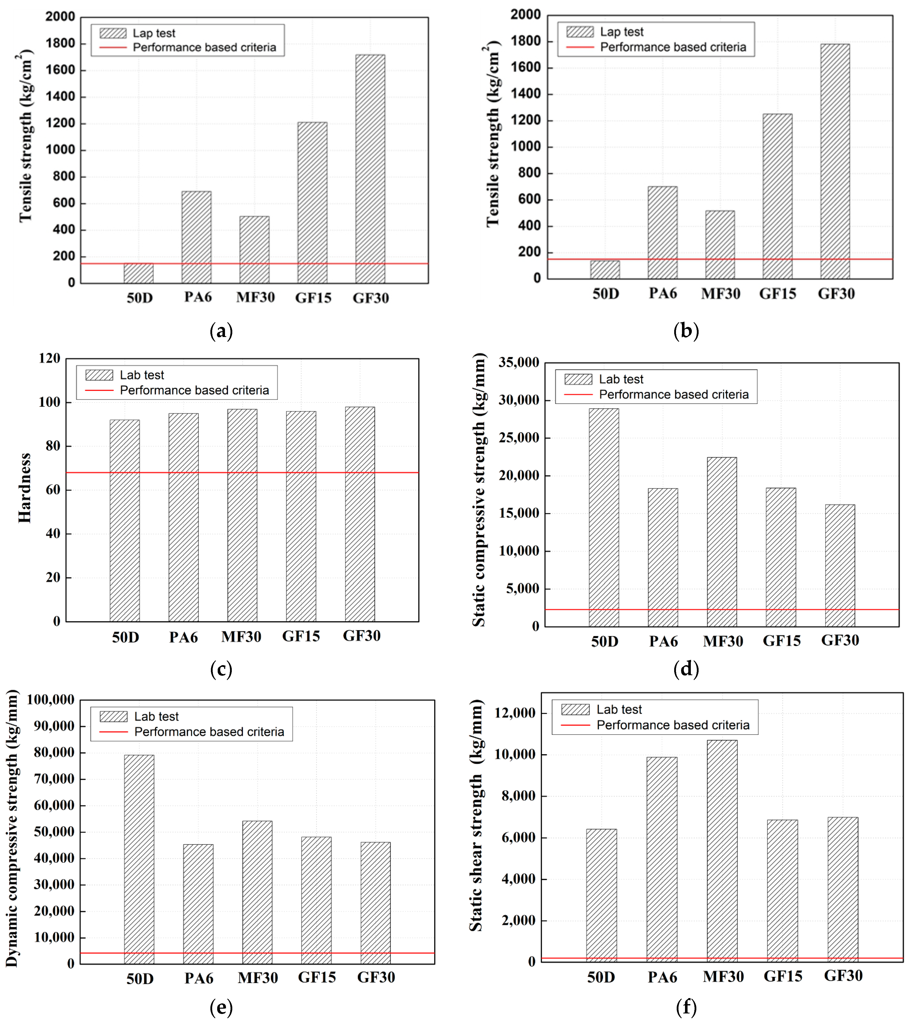
3.1. Indoor Test for Optimal Material Selection for Rubber Boots (Material Test Piece)
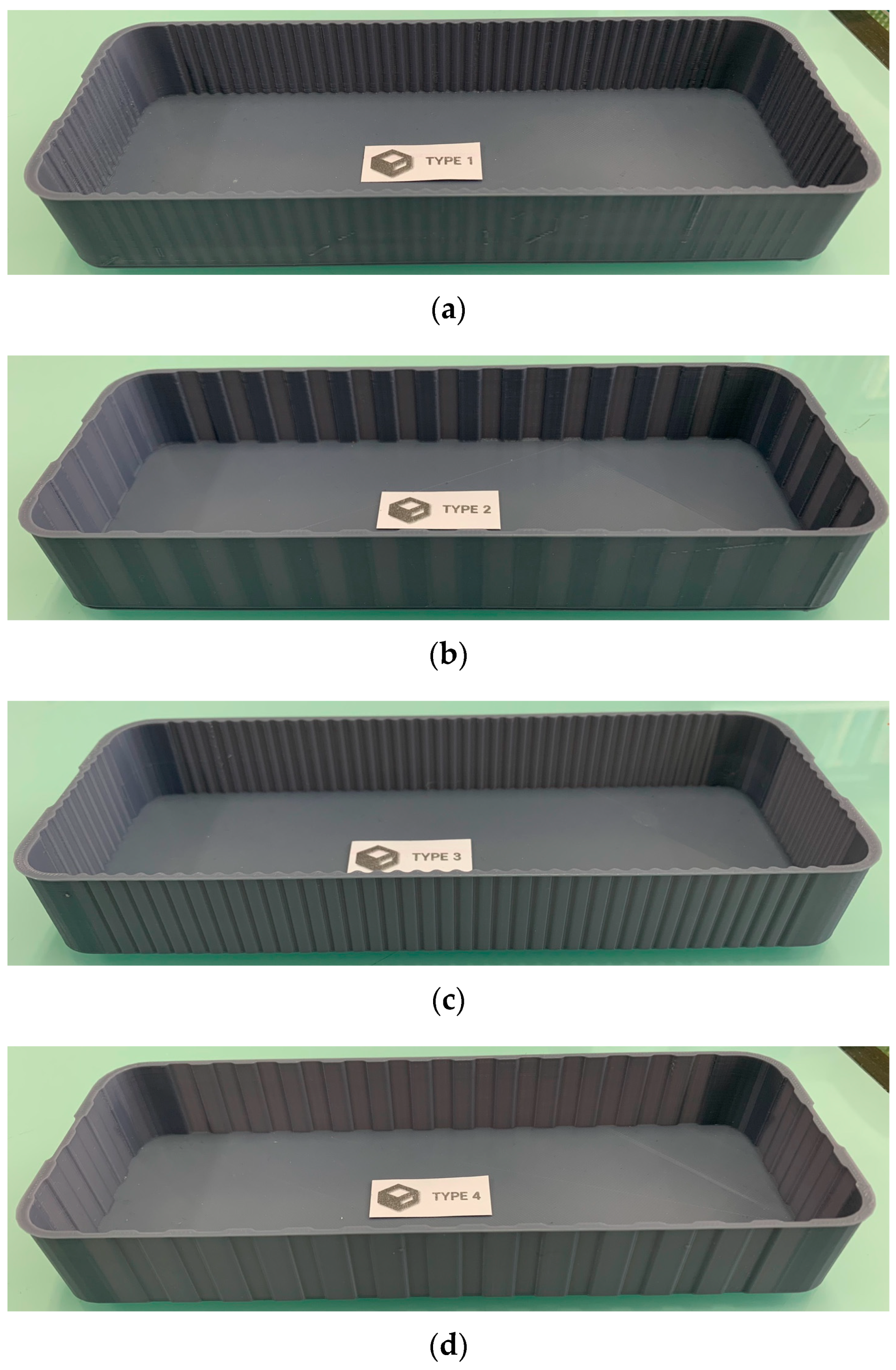
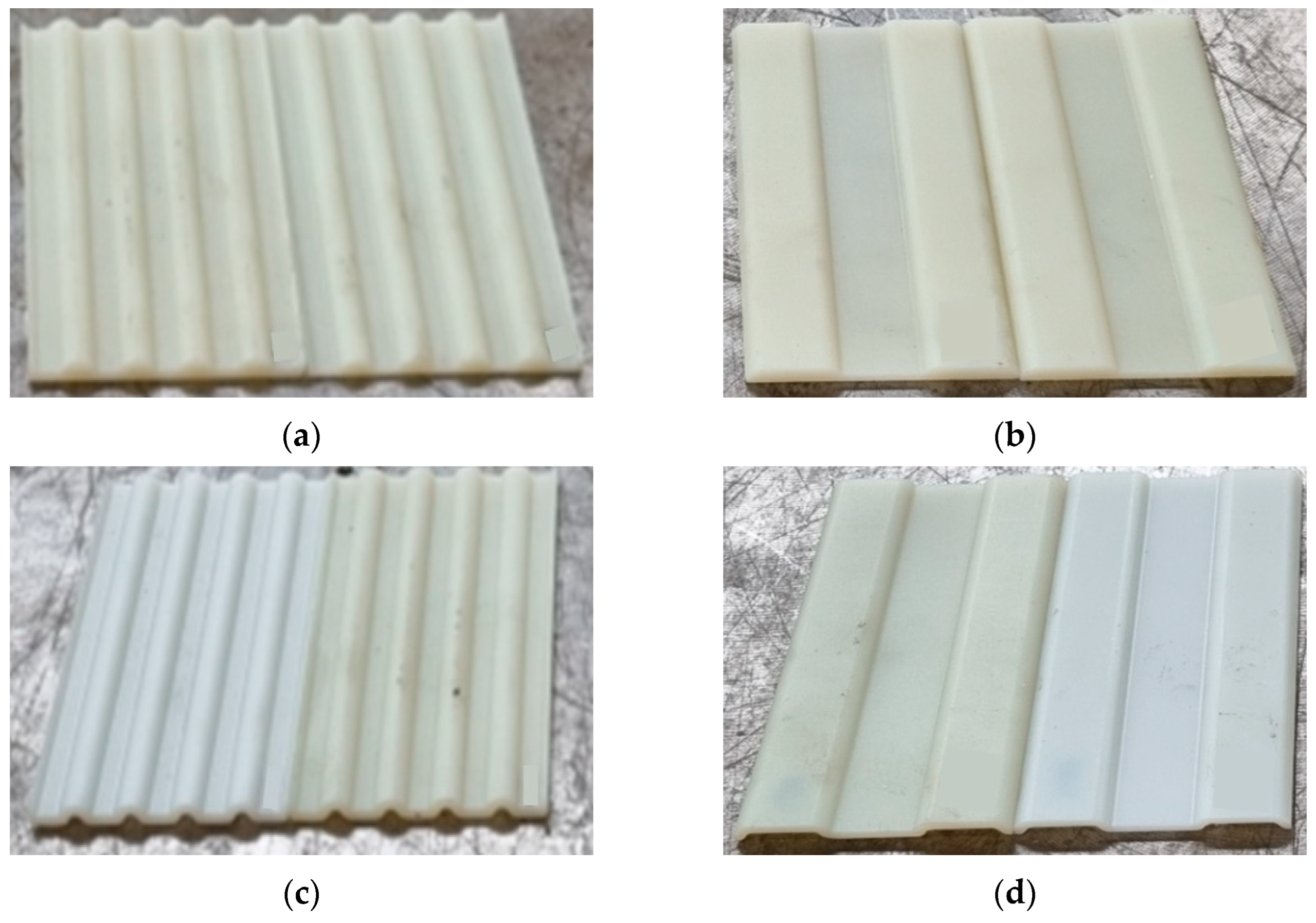
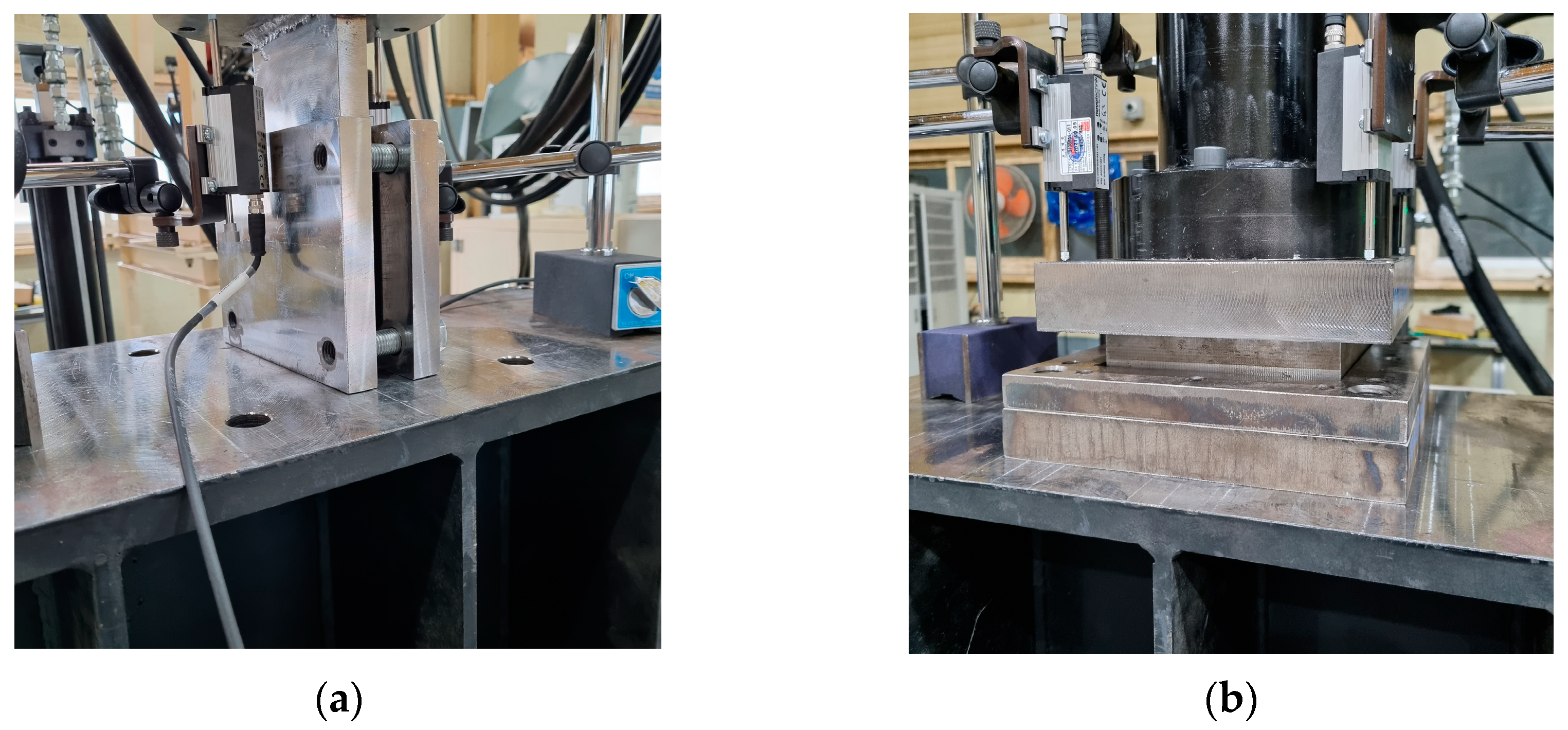
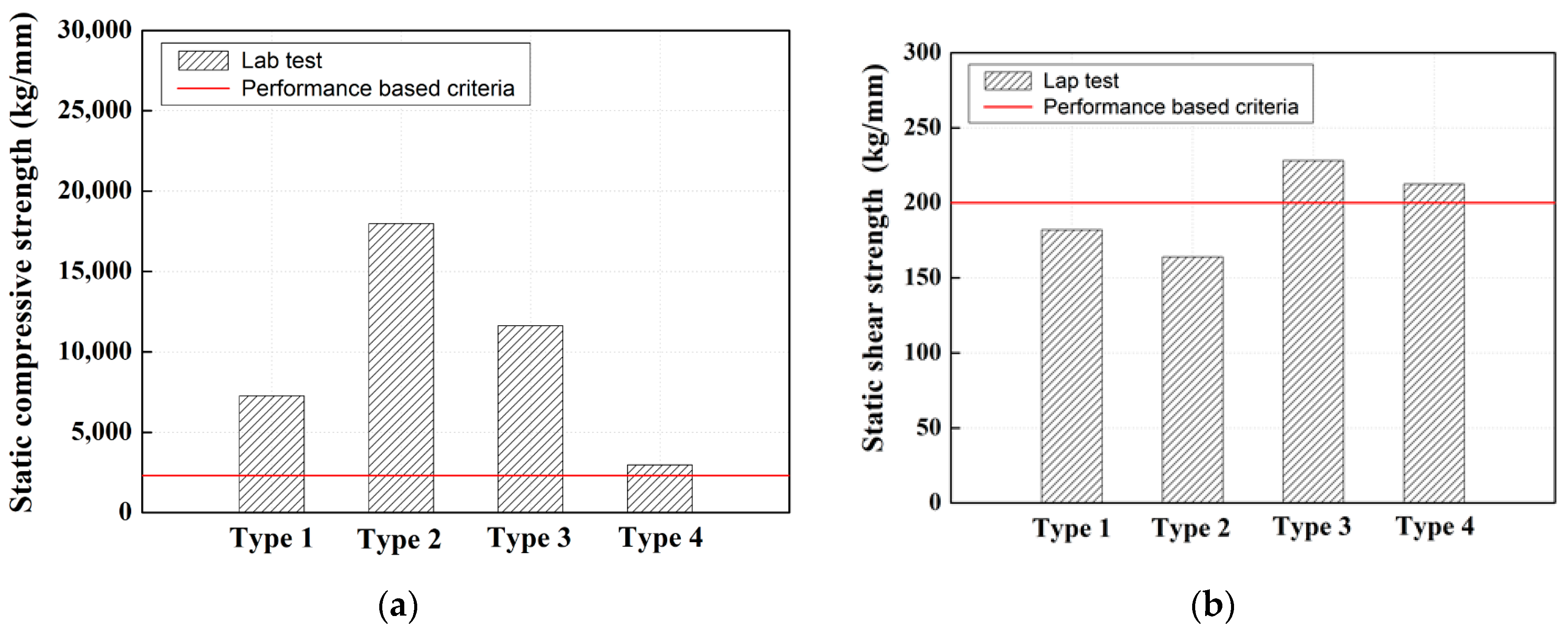
3.2. Indoor Test for Selecting the Optimal Shape of the Rubber Boot (Actual Test Piece)
4. Conclusions
Author Contributions
Funding
Institutional Review Board Statement
Informed Consent Statement
Data Availability Statement
Conflicts of Interest
References
- Choi, J.Y.; Bong, J.G.; Han, J.M.; Chung, J.S. Dynamic behavior of sleeper floating track system (STEDEF) on urban rapid transit according to replacement of resilience pad. J. Converg. Cult. Technol. 2020, 6, 335–340. [Google Scholar]
- Lee, D.W.; Park, Y.G.; Choi, J.Y. A study on the evaluation of track support stiffness on the various track type in urban transit. J. Korean Soc. Railw. 2011, 14, 262–270. [Google Scholar] [CrossRef] [Green Version]
- Kim, H.S. Damage Effect Analysis for Track Components of Sleeper Floating Track in Urban Transit. Ph.D. Thesis, Dongyang University, Yeongju-si, Republic of Korea, February 2021. [Google Scholar]
- Kim, H.S. An Influence of the Fastening Force on the Rail Force of the Curved Track in Urban Railway. Master’s Thesis, Seoul National University of Science and Technology, Seoul, Republic of Korea, February 2016. [Google Scholar]
- Lee, S.S. A Study on the Performance of the Track Reduction Material of Vibration on the Scene of Busan Urban Railway No. 2 Line. Master’s Thesis, Woosong University, Daejeon, Republic of Korea, February 2013. [Google Scholar]
- Vu, L.; Jang, D.D.; Kang, Y.S. Assessment of structural dynamic response and vehicle-track interaction of precast slab track systems. Appl. Sci. 2021, 11, 3558. [Google Scholar] [CrossRef]
- Vu, L.; Kang, Y.S. Land transfer efficiency based on structural deflection assessment of the precast floating track. Appl. Sci. 2021, 11, 120. [Google Scholar] [CrossRef]
- Li, D.; Zhang, Y.; Miao, Q.; Cui, R. Experimental study on the vibration control effect of long elastic sleeper track in subways. Shock Vib. 2018, 2018, 6209518. [Google Scholar]
- Ferdous, W.; Manalo, A.; Erp, G.V.; Aravinthan, T. Evaluation of an innovative composite railway sleeper for a narrow-gauge track under static load. J. Compos. Constr. 2018, 22, 07018001. [Google Scholar] [CrossRef]
- Ferdous, W.; Manalo, A.; Erp, G.V.; Aravinthan, T.; Kaewunruen, S.; Remennikov, A. Composite railway sleepers-recent developments, challenges and future prospects. Compos. Struct. 2015, 135, 158–168. [Google Scholar] [CrossRef]
- Ju, S.; Yoon, J.; Sung, D.; Pyo, S. Mechanical properties of coal ash particle-reinforced recycled plastic-based composites for sustainable railway sleepers. Polymers 2020, 12, 2287. [Google Scholar] [CrossRef] [PubMed]
- Smirnov, V. Dynamic analysis of railway track with vibration isolated booted sleepers. In Proceedings of the MATEC Web of Conferences 196, Rostov-on-Don, Russia, 3 September 2018; Volume 01045. [Google Scholar]
- Gupta, S.; Liu, W.F.; Degrande, G.; Lombaert, G.; Liu, W.N. Prediction of vibrations induced by underground railway traffic in Beijing. J. Sound Vib. 2008, 310, 608–630. [Google Scholar] [CrossRef]
- Kim, S.H. Damage Cause Analysis of Rubber Boots for Sleeper Floating Track System in Urban Transit. Master’s Thesis, Dongyang University, Yeongju-si, Republic of Korea, February 2022. [Google Scholar]
- ANSYS Inc. ANSYS Workbench 2021 R1; ANSYS Inc.: Cannonsberg, PA, USA, 2021. [Google Scholar]
- KS M 6519; Method of Analysis for Rubber Goods. Korean Agency for Technology and Standards: Eumseong, Republic of Korea, 2018.


| Track Component | Material Characteristics | |||
|---|---|---|---|---|
| Young’s Modulus (MPa) | Mass Density (kg/m3) | Poisson’s Ratio (v) | ||
| Rail | 210,000 | 7850 | 0.30 | |
| Rail pad | 200,000 | 7850 | 0.30 | |
| RC block | 72.6 | 950 | 0.20 | |
| Tie bar | 35,000 | 2300 | 0.18 | |
| Rubber boot | 0.98 | 700 | 0.49 | |
| Resilient box | (SBR) | 21.4 | 800 | 0.20 |
| (EP) | 2000 | 1140 | 0.15 | |
| Concrete bed | 35,000 | 2300 | 0.18 | |
| Load Condition | |||
|---|---|---|---|
| Case 1 | Case 2 | ||
| Load Case | Value | Load Case | Value |
| Load case A | Self-weight (Auto cal.) | Load case A | Self-weight (Auto cal.) |
| Load case B | Measured wheel load (87 kN) | Load case B | Assumed rail pressure (4.92 MPa) |
| Load case C | Measured lateral wheel load (39 kN) | Load case combination | Load case (A + B) |
| Load case combination | Load case (A + B + C) | ||
| Property | ASTM | Unit | PA6 | PA6 + ST | PA6 +GF15% | PA6 +GF20% | PA6 +GF30% | PA6 +MF30% |
| Specific gravity | D 792 | - | 1.14 | 1.06 | 1.24 | 1.27 | 1.36 | 1.31 |
| Hardness | D 785 | R-Scale | 120 | 105 | 120 | 121 | 122 | 110 |
| Tensile strength | D 638 | kg/cm2 | 750 | 500 | 1300 | 1400 | 1750 | 500 |
| Elongation | D 638 | % | 50 | 180 | 5 | 3.5 | 3.0 | 10 |
| Flexural strength | D 790 | kg/cm2 | 1050 | 450 | 1700 | 1900 | 2300 | 700 |
| Flexural modulus | D 790 | kg/cm2 | 25,000 | 140 | 48,000 | 53,000 | 79,000 | 30,000 |
| Impact strength | D 256 | kg.cm/cm | 4.5 | 60.0 | 6.0 | 8.0 | 9.0 | 8.0 |
| Melting point | D S C | °C | 220 | 220 | 220 | 220 | 220 | 220 |
| Heat-deflection temperature | D 648 | °C | 175 | 120 | 205 | 220 | 220 | 150 |
| Flame resistance | 18.6 kg/cm2 | 50 | 190 | 205 | 210 | 60 | ||
| Mold shrinkage rate | UL 94 | - | HB | HB | HB | HB | HB | HB |
| Quality | D 955 | % | 1.4 | 1.8 | 0.7 | 0.6 | 0.5 | 0.3 |
| Test Item | Unit | Performance Requirements (Performance Criteria) | Target | Experiment Result | Test Code | |
|---|---|---|---|---|---|---|
| 1. Hardness | Shore A | 58~68 | 68 | 98 | KRSA-T-2017-1001-R0 | |
| 2. Tensile strength | kg/cm2 | Before aging | After aging | 150 or more before and after aging | 1783 before and after aging | ASTM D638 |
| 150 | 120 | |||||
| 3. Static shear strength | kg/mm | 200 or less | 200 or more | 10,706 | KRSA-T-2017-1001-R0 | |
| 4. Static compressive strength | kg/mm | 1200~2300 | 2300 or more | 28,915 | KRSA-T-2017-1001-R0 | |
| 5. Dynamic Compressive Strength | kg/mm | 2000~4200 | 4200 or more | 79,251 | KRSA-T-2017-1001-R0 | |
Disclaimer/Publisher’s Note: The statements, opinions and data contained in all publications are solely those of the individual author(s) and contributor(s) and not of MDPI and/or the editor(s). MDPI and/or the editor(s) disclaim responsibility for any injury to people or property resulting from any ideas, methods, instructions or products referred to in the content. |
© 2023 by the authors. Licensee MDPI, Basel, Switzerland. This article is an open access article distributed under the terms and conditions of the Creative Commons Attribution (CC BY) license (https://creativecommons.org/licenses/by/4.0/).
Share and Cite
Choi, J.-Y.; Kim, S.-H.; Park, H.S.; Chung, J.-S. A Study on Development of New Type Rubber Boot for Sleeper Floating Track System (STEDEF): Materials and Shapes. Appl. Sci. 2023, 13, 3068. https://doi.org/10.3390/app13053068
Choi J-Y, Kim S-H, Park HS, Chung J-S. A Study on Development of New Type Rubber Boot for Sleeper Floating Track System (STEDEF): Materials and Shapes. Applied Sciences. 2023; 13(5):3068. https://doi.org/10.3390/app13053068
Chicago/Turabian StyleChoi, Jung-Youl, Sun-Hee Kim, Hee Soo Park, and Jee-Seung Chung. 2023. "A Study on Development of New Type Rubber Boot for Sleeper Floating Track System (STEDEF): Materials and Shapes" Applied Sciences 13, no. 5: 3068. https://doi.org/10.3390/app13053068