

Crashworthiness Analysis to Evaluate the Performance of TDM-Shielded Street Poles Using FEA

Abstract
:1. Introduction
- To justify the use of discarded tires as a source to manufacture shielding for street poles through simulation of their function.
- To highlight the reduction of the risk of injury to the passenger by implanting TDM-based reinforcements on street poles.
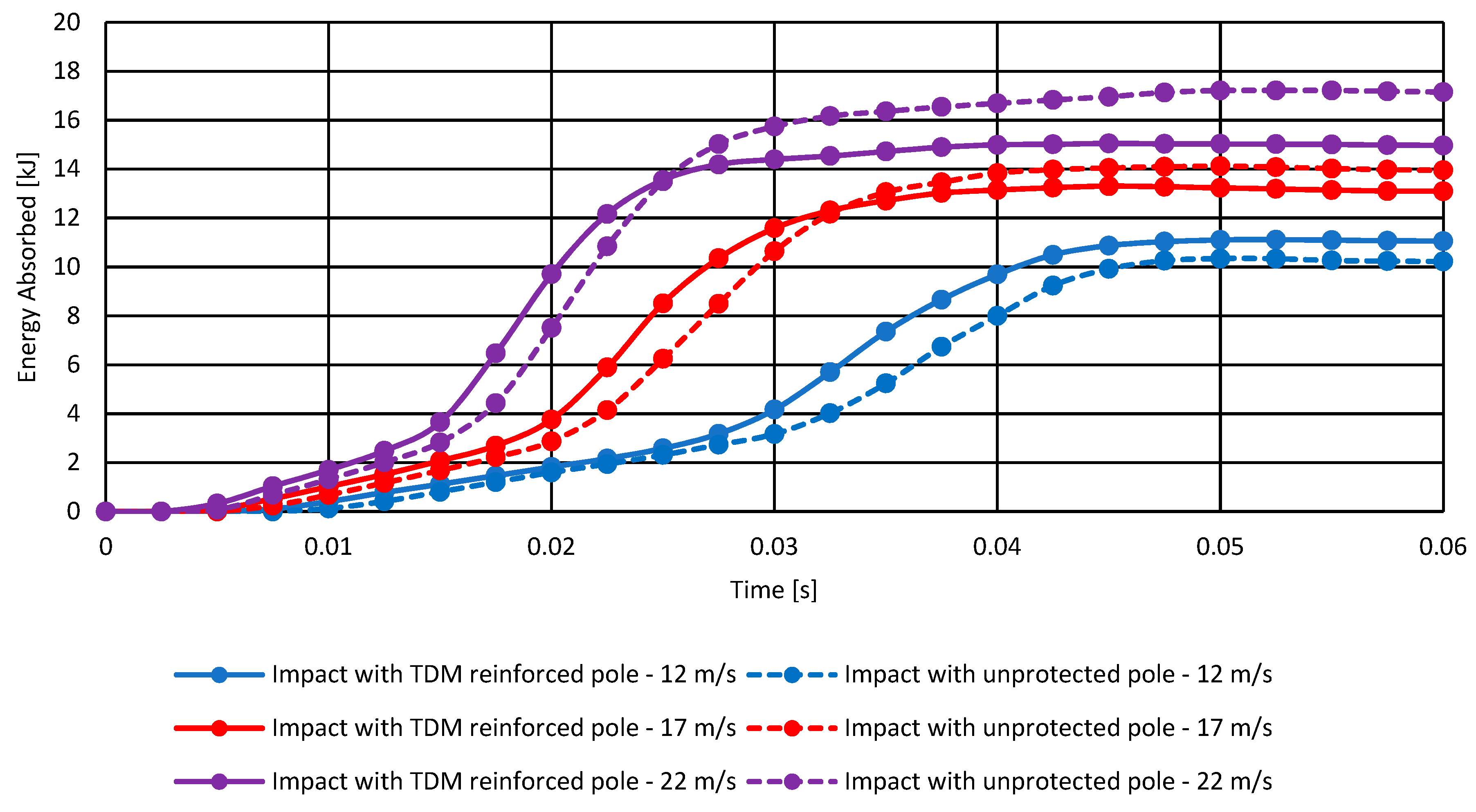
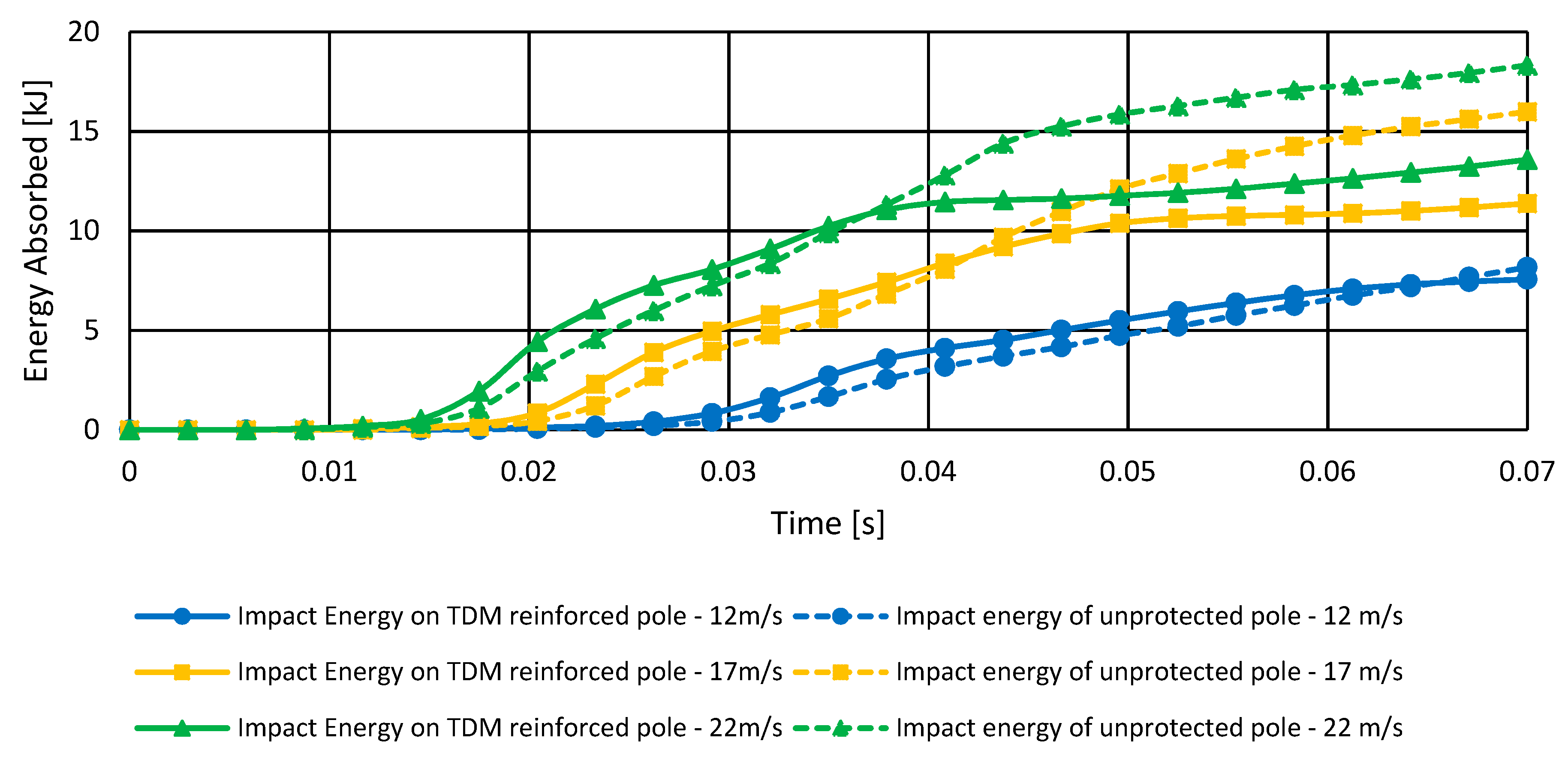
- The impact energies were mitigated on the street pole and vehicle due to the presence of TDM shielding.
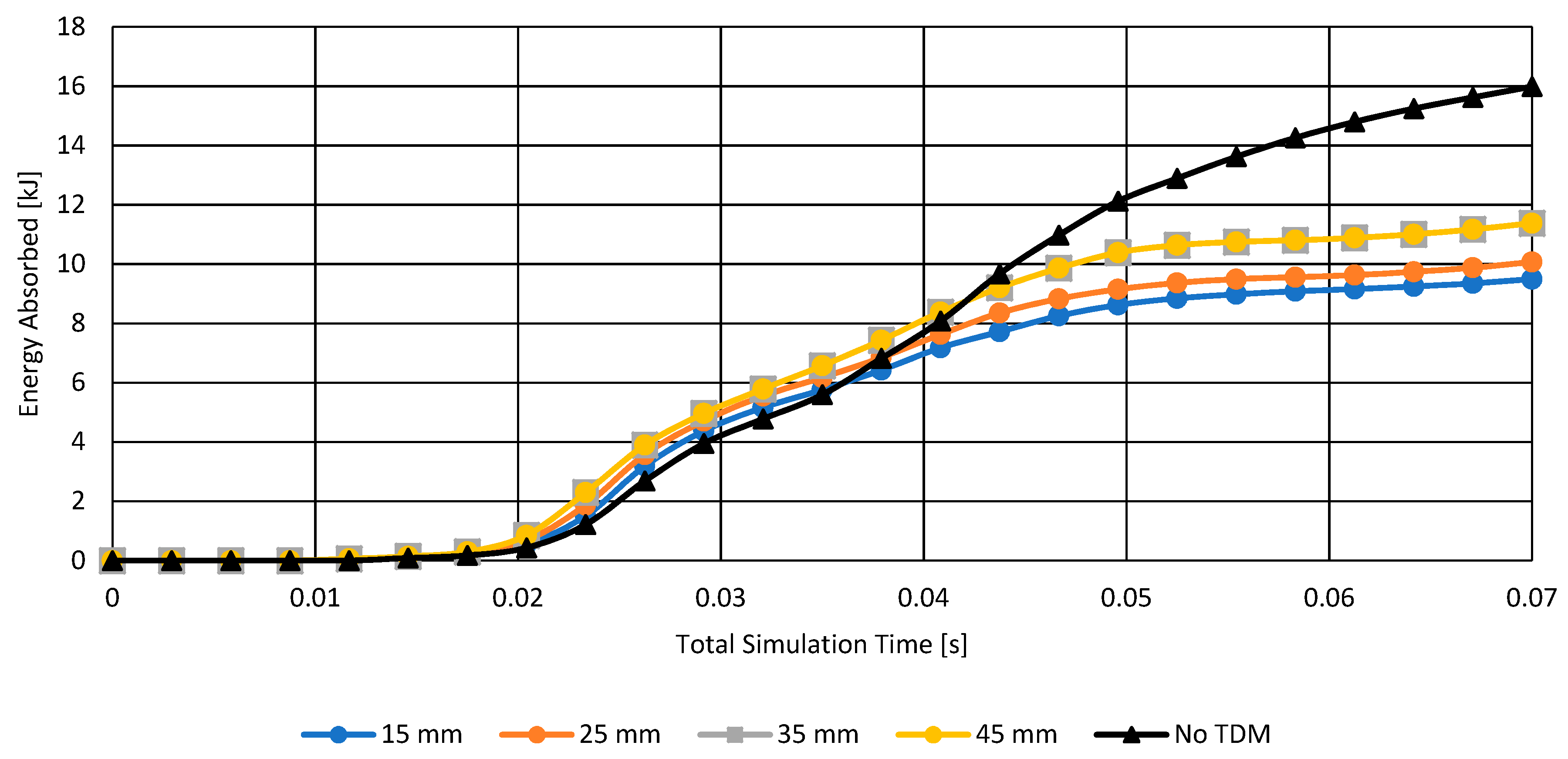
- An initial study on the optimal thickness of the street pole shielding is required to have maximum mitigation of impact energy for both the vehicle and the street pole.
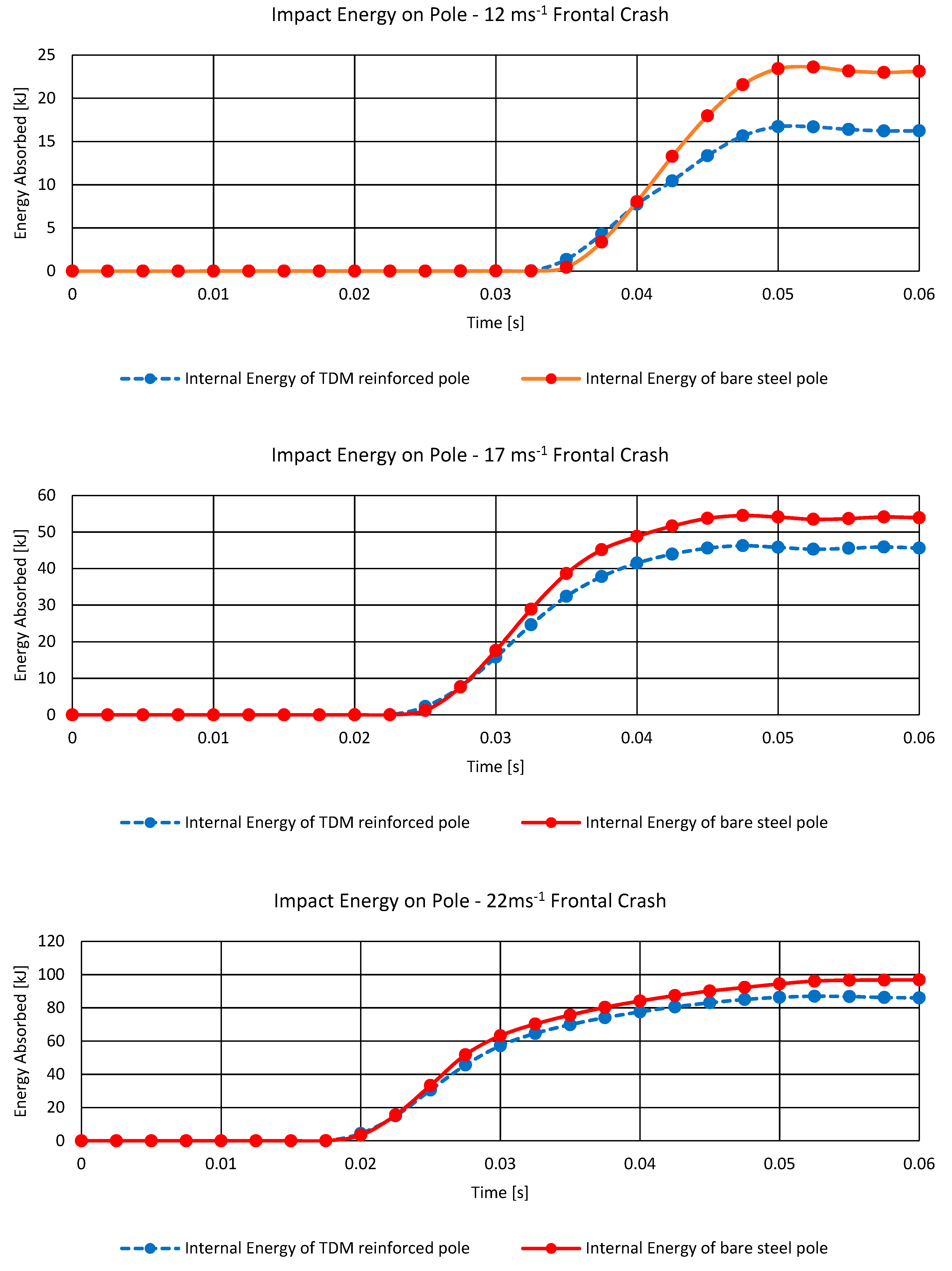
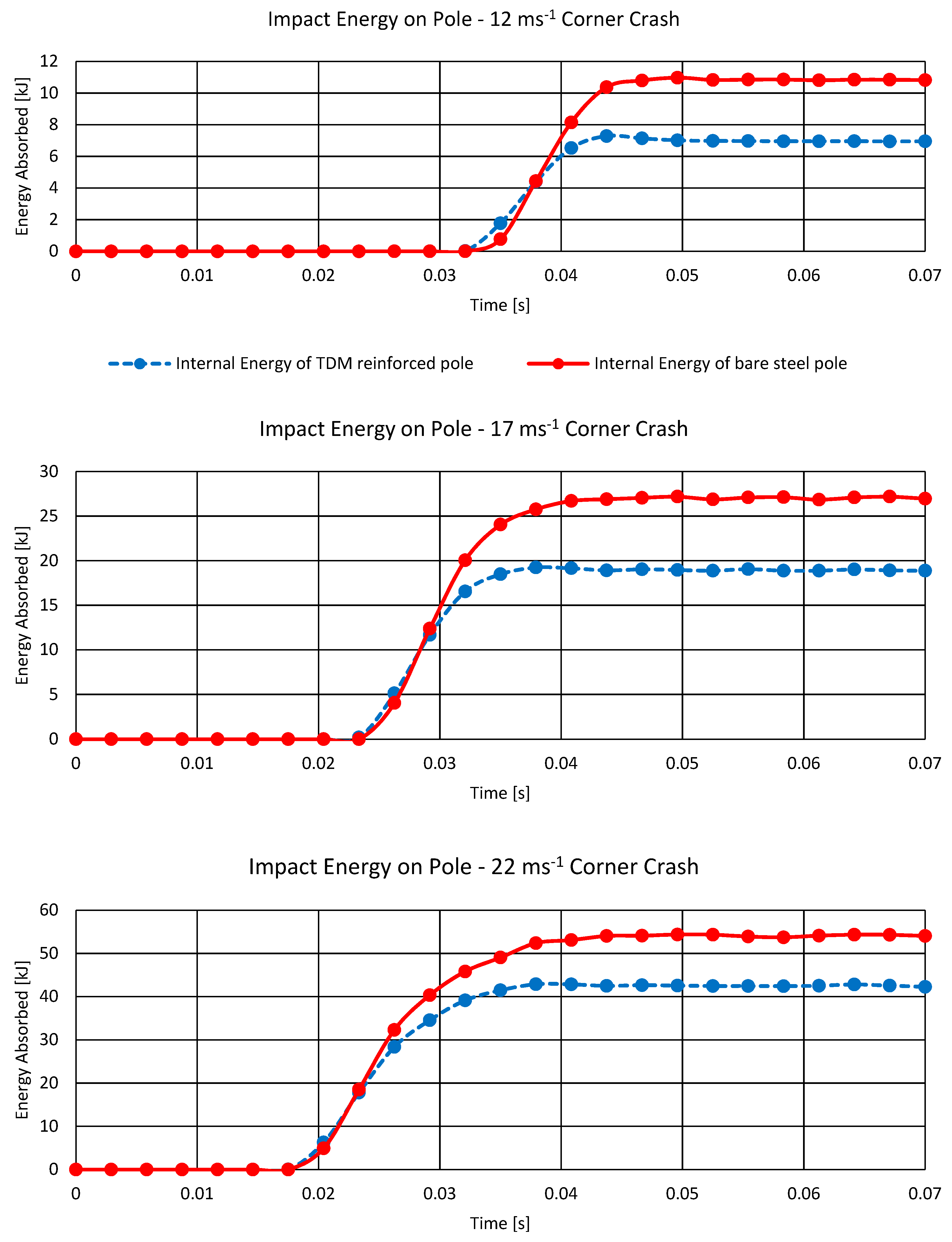
- A study on the variation of the vehicle’s velocities and its influence on the TDM shielding’s mitigation of impact energy.
2. Literature Review
2.1. Constitutive Equations of Explicit Dynamics
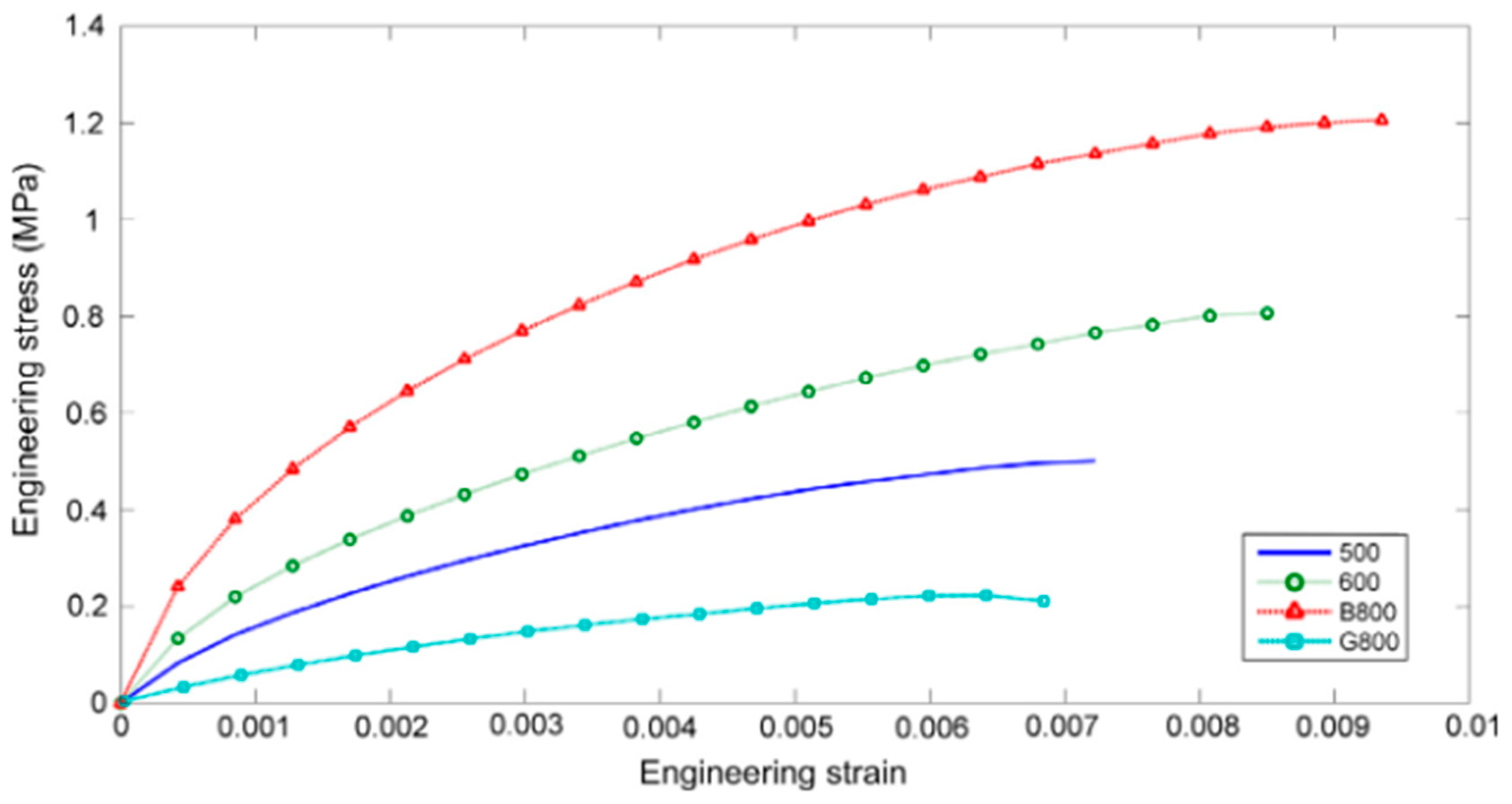
2.2. Constitutive Equations of Hyperelastic Materials
3. Methodology
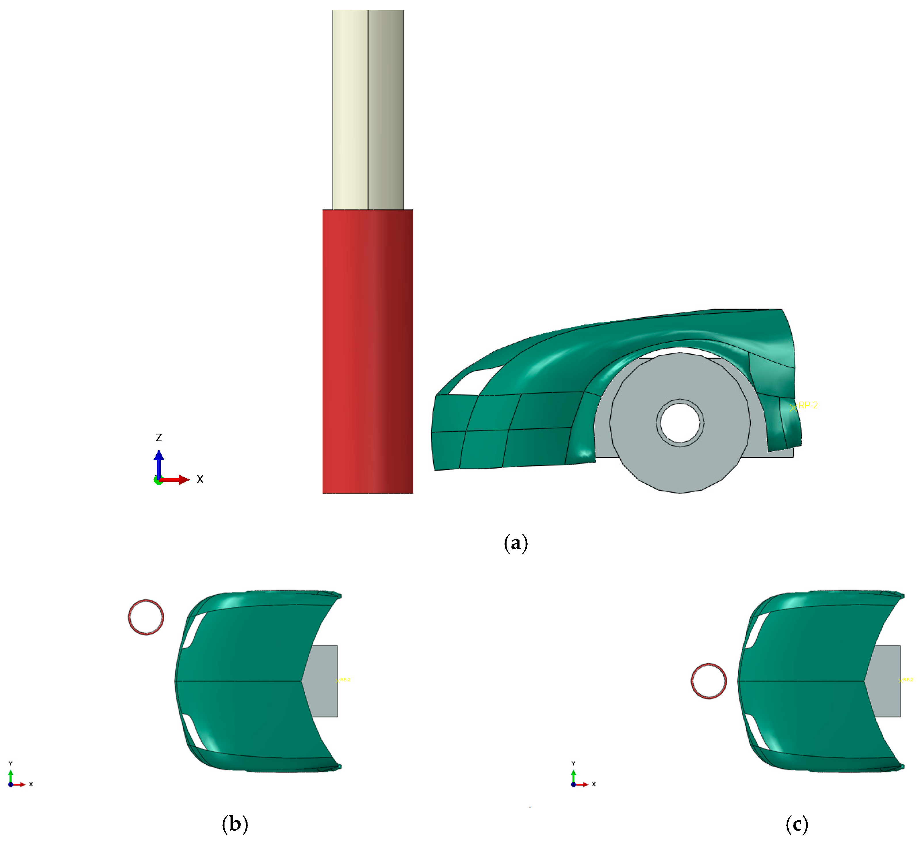
3.1. 3D Model of the Vehicle
3.2. 3D Model of the Street Pole
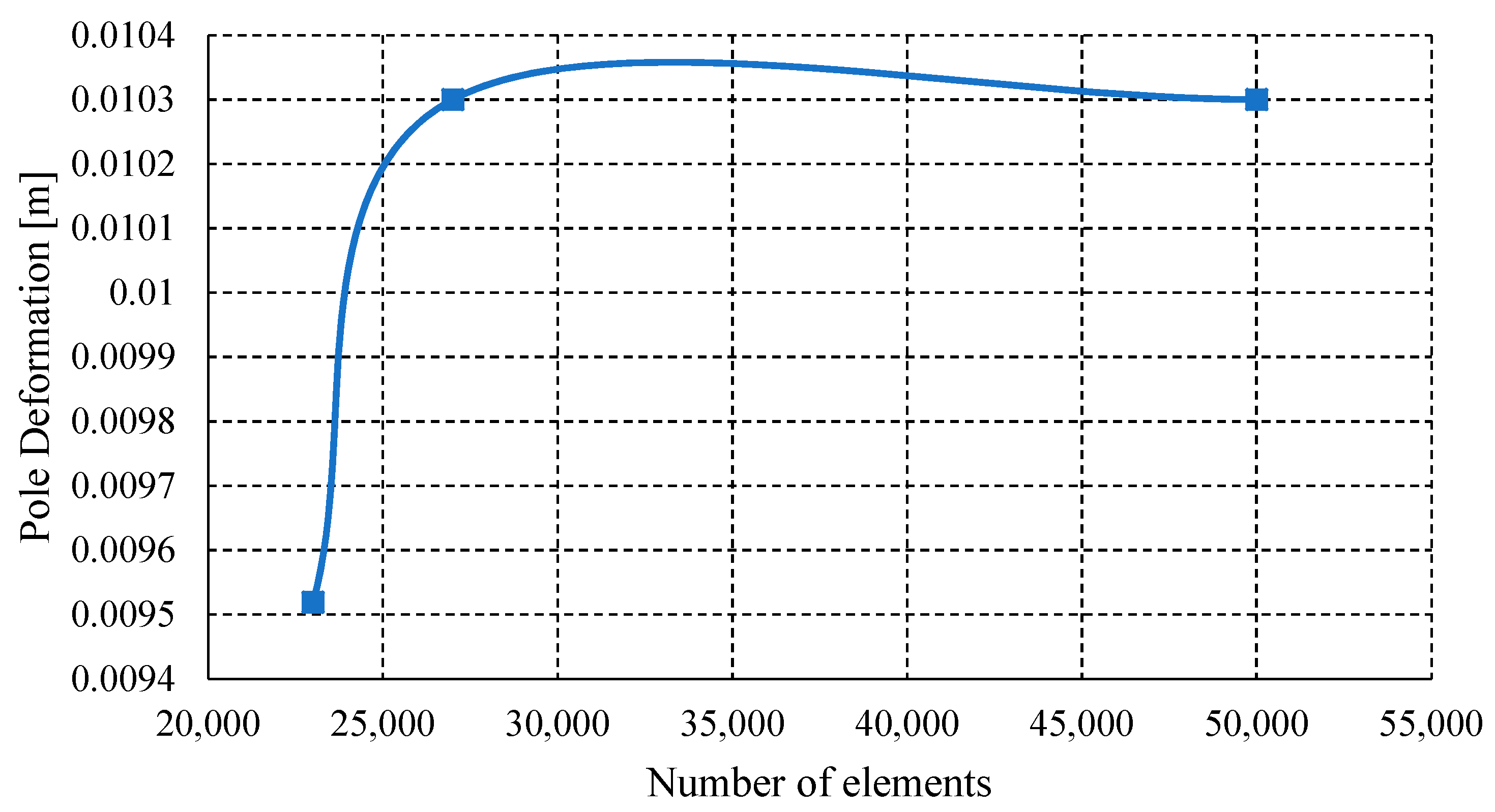
3.3. FEA Model
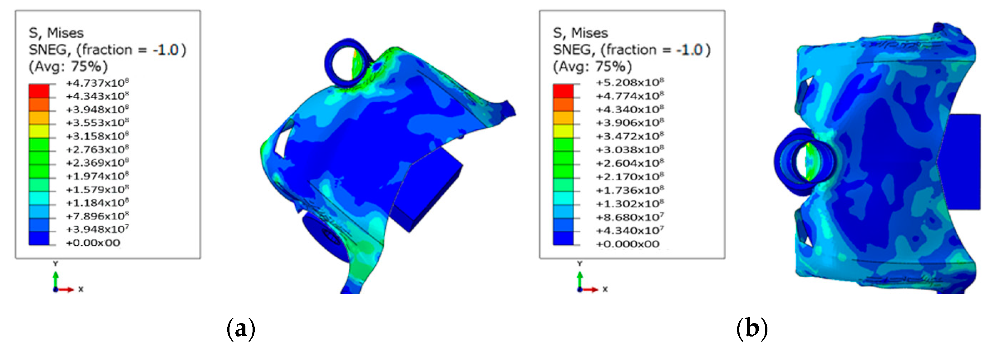
4. Results
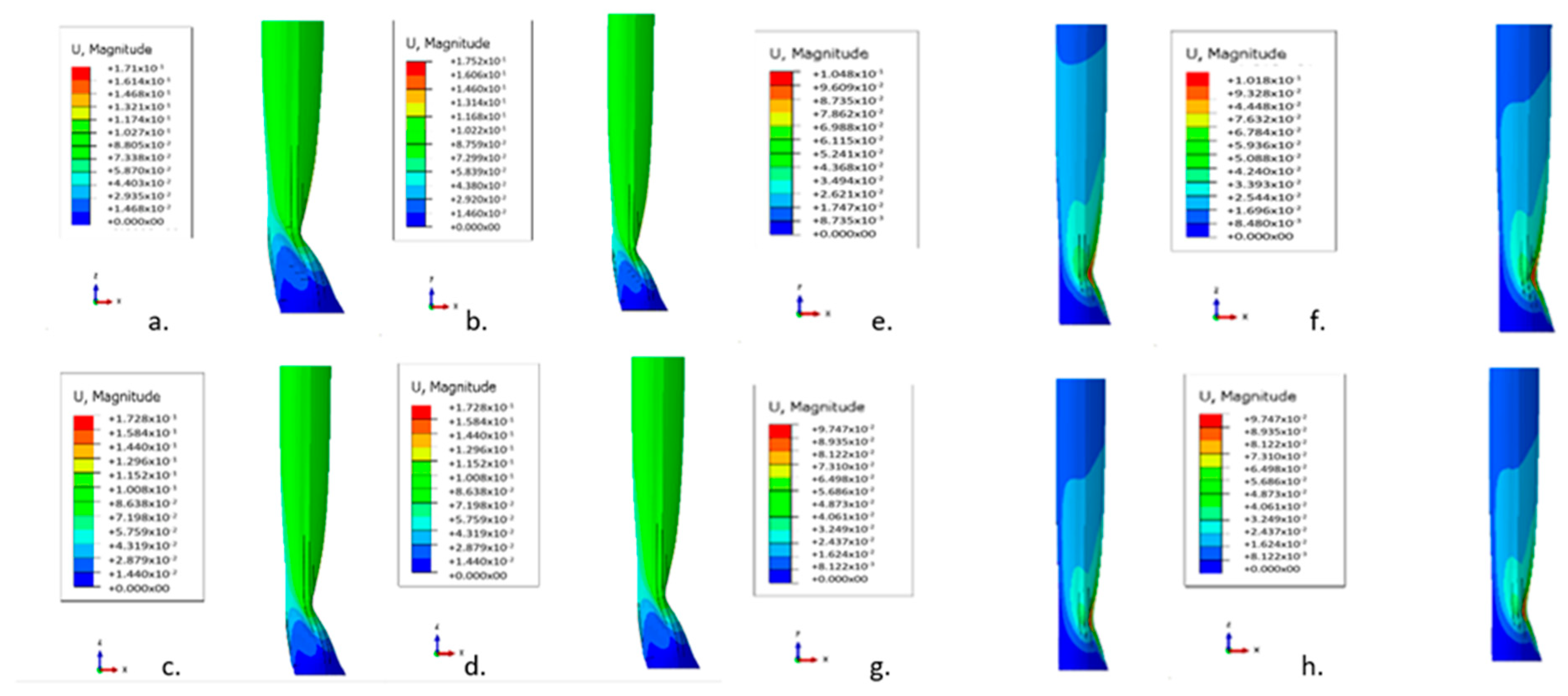
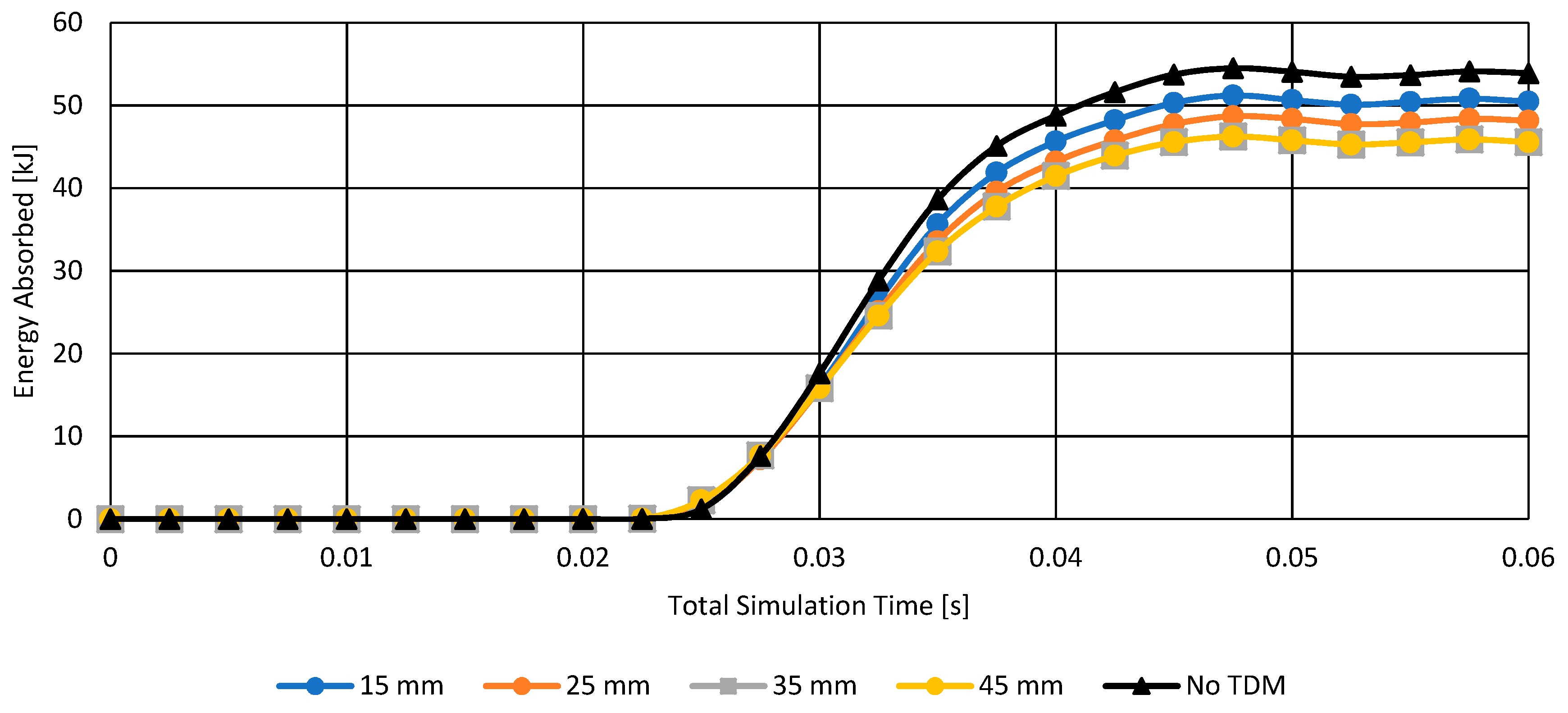
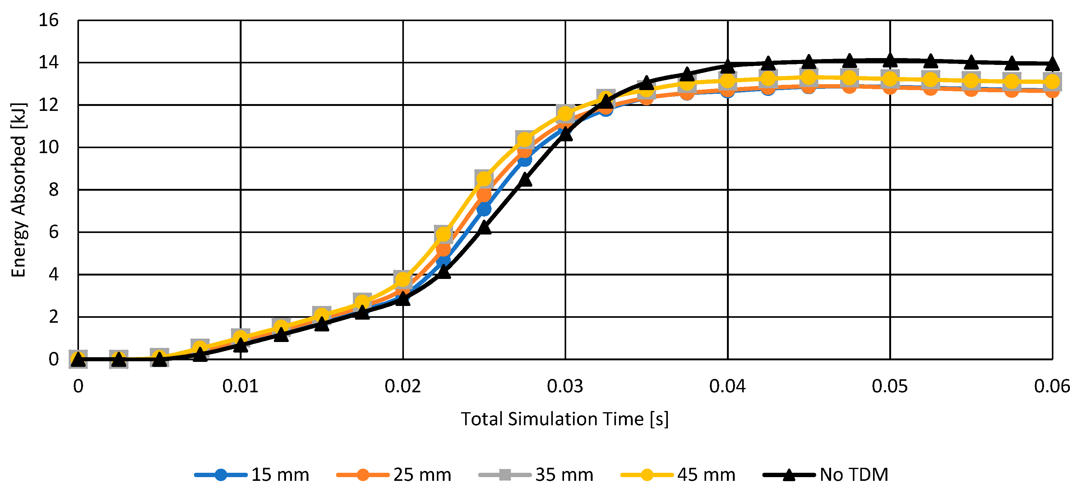
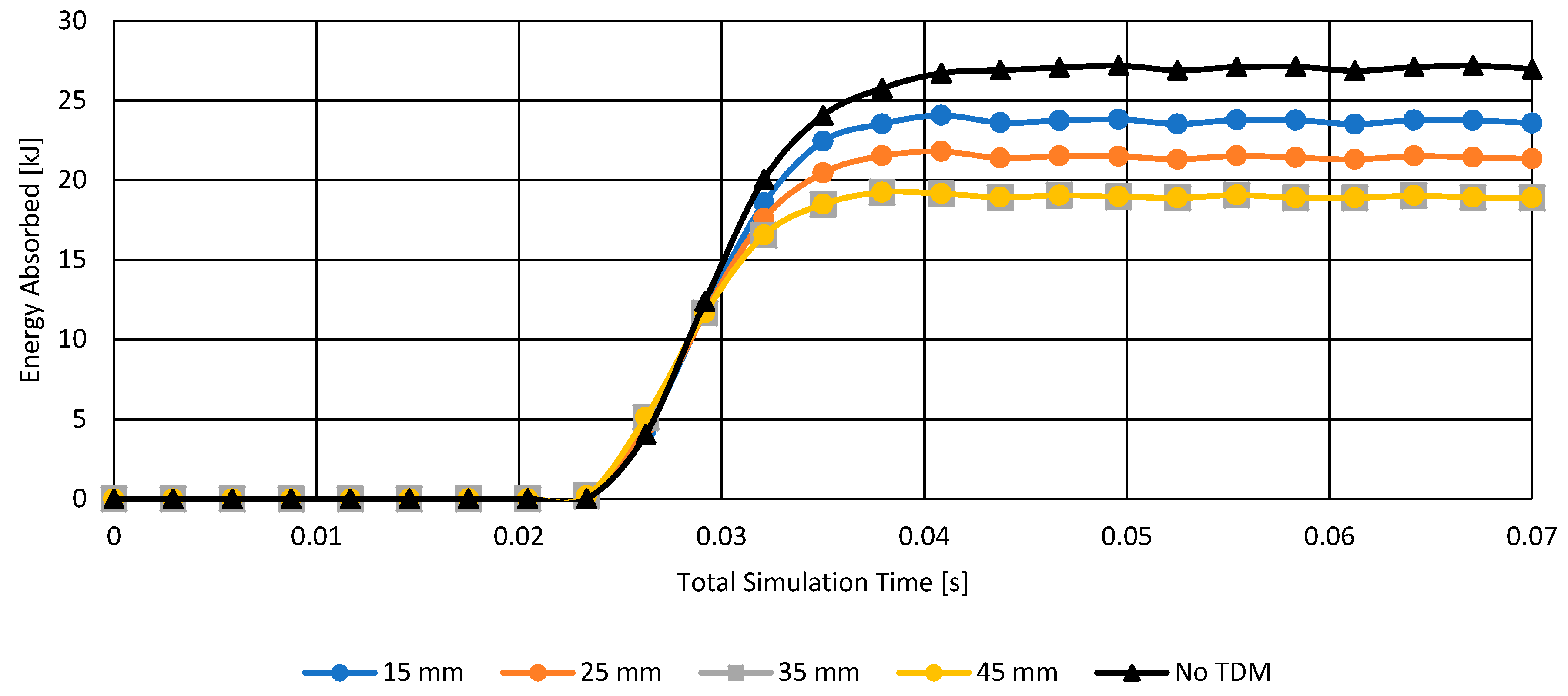
4.1. Parameterisation of TDM Thickness on Impact Energy Absorption on Street Pole and Vehicle
4.2. Variation of Vehicle Velocity on the Impact Energy Absorption on Street Pole and Vehicle
5. Conclusions
Author Contributions
Funding
Institutional Review Board Statement
Informed Consent Statement
Data Availability Statement
Conflicts of Interest
References
- Alardhi, M.; Sequeira, R.; Fahed, M.; Alrajhi, J.; Alkhulaifi, K. Assessing the Crashworthiness Analysis on Frontal and Corner Impacts of Vehicle on Street Poles Using FEA. Appl. Sci. 2022, 12, 12287. [Google Scholar] [CrossRef]
- Ispas, N.; Nastasoiu, M. Analysis of car’s frontal collision against pole. IOP Conf. Ser. Mater. Sci. Eng. 2017, 252, 012012. [Google Scholar] [CrossRef]
- Elmarakbi, A.; Sennah, K.; Samaan, M.; Siriya, P. Crashworthiness of motor vehicle and traffic light pole in frontal collisions. J. Transp. Eng. 2006, 132, 722–733. [Google Scholar] [CrossRef]
- Long, K.; Gao, Z.; Yuan, Q.; Xiang, W.; Hao, W. Safety evaluation for roadside crashes by vehicle–object collision simulation. Adv. Mech. Eng. 2018, 10, 1–12. [Google Scholar] [CrossRef]
- Federal Competitiveness and Statistics Centre. Traffic Accidents by Emirate and Cause of Accident; Bayanat: Abu Dhabi, United Arab Emirates, 2018. [Google Scholar]
- Beyene, A.T.; Koricho, E.G.; Belingardi, G.; Martorana, B. Design and Manufacturing Issues in the Development of Lightweight Solution for a Vehicle Frontal Bumper. Procedia Eng. 2014, 88, 77–84. [Google Scholar] [CrossRef]
- Liu, Z.; Lu, J.; Zhu, P. Lightweight design of automotive composite bumper system using modified particle swarm optimizer. Compos. Struct. 2016, 140, 630–643. [Google Scholar] [CrossRef]
- Ahamed, T.I.; Sundarrajan, R.; Prasaath, G.T.; Raviraj, V. Implementation of Magneto-rheological Dampers in Bumpers of Automobiles for Reducing Impacts during Accidents. Procedia Eng. 2014, 97, 1220–1226. [Google Scholar] [CrossRef]
- Ferdous, W.; Manalo, A.; Siddique, R.; Mendis, P.; Zhuge, Y.; Wong, H.S.; Lokuge, W.; Aravinthan, T.; Schubel, P. Recycling of landfill wastes (tyres, plastics and glass) in construction—A review on global waste generation, performance, application and future opportunities. Resour. Conserv. Recycl. 2021, 173, 105745. [Google Scholar] [CrossRef]
- Singh, A.; Spak, S.N.; Stone, E.A.; Downard, J.; Bullard, R.L.; Pooley, M.; Kostle, P.A.; Mainprize, M.W.; Wichman, M.D.; Peters, T.M.; et al. Uncontrolled combustion of shredded tires in a landfill—Part 2: Population exposure, public health response, and an air quality index for urban fires. Atmos. Environ. 2015, 104, 273–283. [Google Scholar] [CrossRef] [PubMed]
- Xu, J.; Yao, Z.; Yang, G.; Han, Q. Research on Crumb Rubber Concrete: From a Multi-scale Review. Constr. Build. Mater. 2019, 232, 117282. [Google Scholar] [CrossRef]
- Revelo, C.F.; Correa, M.; Aguilar, C.; Colorado, H.A. Composite Materials Made of Waste Tires and Polyurethane Resin: A Case Study of Flexible Tiles Successfully Applied in Industry; Elsevier: Amsterdam, The Netherlands, 2021. [Google Scholar]
- Dassault Systèmes. “Abaqus/Explicit”. Dassault Systèmes User Assistance. Available online: https://www.3ds.com/products-services/simulia/products/abaqus/abaqusexplicit/ (accessed on 11 February 2022).
- Deb, A. Crashworthiness Design Issues for Lightweight Vehicles; Woodhead Publishing: Sawston, UK, 2021. [Google Scholar]
- Sun, G.; Deng, M.; Zheng, G.; Li, Q. Design for cost performance of crashworthy structures made of high strength steel. Thin-Walled Struct. 2019, 138, 458–472. [Google Scholar] [CrossRef]
- ASTM. Standard Test Methods for Vulcanized Rubber and Thermoplastic Elastomers—Tension; ASTM: West Conshohocken, PA, USA, 2021. [Google Scholar]
- Montella, G.; Calabrese, A.; Serino, G. Mechanical characterization of a Tire Derived Material: Experiments, hyperelastic modeling and numerical validation. Constr. Build. Mater. 2014, 66, 336–347. [Google Scholar] [CrossRef]
- Dassault Systemes. Isotropic Hyperelasticity-User Assistance R2022x. Available online: https://info.simuleon.com/blog/abaqus-2020-download-installation, (accessed on 3 February 2022).


| Material | Young’s Modulus [GPa] | Poisson’s Ratio | Yield Stress [MPa] | Density [kgm−3] |
|---|---|---|---|---|
| Aluminium-5052 | 68.9 | 0.33 | 140 | 2690 |
| Aluminium-6061 | 69.5 | 0.33 | 220 | 2780 |
| Steel ASTM A36 | 210 | 0.29 | 247.5 | 7869 |
| Material | Fracture Strain | Displacement after Fracture [m] |
|---|---|---|
| Aluminium-5052 | 0.105 | 0.002625 |
| Aluminium-6061 | 0.061 | 0.001525 |
| Steel ASTM A36 | 0.24 | 0.006 |
Disclaimer/Publisher’s Note: The statements, opinions and data contained in all publications are solely those of the individual author(s) and contributor(s) and not of MDPI and/or the editor(s). MDPI and/or the editor(s) disclaim responsibility for any injury to people or property resulting from any ideas, methods, instructions or products referred to in the content. |
© 2023 by the authors. Licensee MDPI, Basel, Switzerland. This article is an open access article distributed under the terms and conditions of the Creative Commons Attribution (CC BY) license (https://creativecommons.org/licenses/by/4.0/).
Share and Cite
Alardhi, M.; Sequeira, R.; Melad, F.; Alrajhi, J.; Alkhulaifi, K. Crashworthiness Analysis to Evaluate the Performance of TDM-Shielded Street Poles Using FEA. Appl. Sci. 2023, 13, 4393. https://doi.org/10.3390/app13074393
Alardhi M, Sequeira R, Melad F, Alrajhi J, Alkhulaifi K. Crashworthiness Analysis to Evaluate the Performance of TDM-Shielded Street Poles Using FEA. Applied Sciences. 2023; 13(7):4393. https://doi.org/10.3390/app13074393
Chicago/Turabian StyleAlardhi, Mohsen, Rahul Sequeira, Fahed Melad, Jasem Alrajhi, and Khalid Alkhulaifi. 2023. "Crashworthiness Analysis to Evaluate the Performance of TDM-Shielded Street Poles Using FEA" Applied Sciences 13, no. 7: 4393. https://doi.org/10.3390/app13074393