1. Introduction
The cervical spine, which is considered the human neck, is the upper region of the vertebral column and a common injury site. Severe cervical injuries are often associated with damage to the spinal cord, which can lead to permanent disabilities [
1], and in the worst cases can even lead to death. However, most neck injuries are minor injuries with a low threat to life. One of the most common neck injuries is whiplash; the plethora of clinical symptoms and sequelae have been classified as whiplash-associated disorders (WAD) [
2]. Whiplash can result from sports accidents, physical abuse, and other types of traumas, such as falls; it is most commonly caused in automotive collisions [
3], especially rear-end impact crashes. The annual incidence of whiplash is estimated at around 300 cases per 100,000 inhabitants in North America and Western Europe [
4]. It is estimated that approximately 40% of whiplash patients develop chronic neck pain and headache [
5].
Thus, studying how the body behaves in such situations is necessary to develop ways to treat or even prevent such injuries. There are three types of studies that can be employed to obtain data: in vivo studies, in vitro studies, and computational models. In vivo testing has been reduced for both legal and ethical reasons, as well as the potential for injury. In vitro studies require cadaveric subjects; the repeated use of samples results in their deterioration, which translates into less precise results. Computational models are more appealing, as they offer unique features such as being able to provide information that cannot be easily obtained in other studies, for example, internal stresses or strains, the ease of rapidly simulating different situations, and the ability to be used repeatedly for multiple experiments with uniform consistency, which lowers costs [
6]. Therefore, they have become the most widely used approach.
The first computational models of the cervical spine had simple geometries [
7,
8,
9]; today, however, advances in technology have led to the development of models that more accurately simulate the behavior of the cervical spine. Over the years, two types of approaches have been used to generate of the geometry, namely, the parametric and the precise reconstruction. Both normally provide reasonable spinal behavior, although both have their advantages and disadvantages.
Using parametric studies to generate the model geometry reduces its complexity while providing reasonable results of the simulation of spinal behavior. It diminishes computation times, makes visualization easier, and allows for the correction of geometric dimensions if necessary. Their main disadvantage is that they do not represent the actual geometry of the cervical spine, and therefore do not present the most accurate results. Maurel et al. [
10] is an example of a study using only parametric studies to model the cervical components.
The use of medical images for geometry acquisition, such as computer tomography (CT) and magnetic resonance imaging (MRI), can result in a more bio-realistic model. This approach has become more prevalent thanks to programs that allow for easy manipulation of medical, biomedical, and related imaging. Although more time-consuming for both model acquisition and computer simulations, it provides the most reliable results. The model developed by Kallemeyn et al. [
11] uses medical images to obtain most of its geometry.
The combination of these two approaches, parametric and precise reconstruction, has become a widely used methodology. Östh et al. [
12] used medical images to model the vertebrae, as these are the most complicated parts to develop due to their irregular shape, then used parametric studies for the rest of the components. Moreover, other models have used the mesh definition of adjacent vertebrae to obtain the intervertebral discs [
13,
14].
Recently, Cai et al. [
15] developed and validated a precise model of the lower cervical spine to study how cervical disc degeneration affects the motion loading method on facet joint forces. For this, the original model was modified to create six degenerative models simulating mild, moderate, and severe grades of disc degeneration at the C5–C6 level. The model developed by Wo et al. [
16] to accurately represent the C2–C7 segment was validated and then used to access the biomechanical response of cervical disc replacement using a self-designed prosthesis. A review of these studies is essential to comprehending the approaches that have been used previously, and consequently, to understanding how to approach the subject. Additionally, these studies may be used in other fields, including cervical injury prevention, implant design, and surgical planning. Furthermore, if any model modifications are required, they can be easily preformed.
This work focuses on the creation of a new model of the human cervical spine, applying the method of combining medical images and parametric studies to accurately represent most of its components, such as the vertebrae, the intervertebral discs, the facet joints, and the different ligaments in order to the begin the validation process. The completed model can help to better understand the kinematics of the cervical spine, with a focus on how injuries occur, by providing data that would otherwise not be possible to obtain. Furthermore, coupling the created model with a 3D model of the head can allow for even more accurate simulations.
2. Materials
In this work, a finite element model of the cervical spine (consisting of the C1–C7 segment) was developed. After extensive research through the relevant literature [
11,
12,
13,
14,
15,
17], it was concluded that four different components had to be modeled, each with its own subdivisions. These were the cervical vertebrae with its cortical and cancellous bone and the corresponding intervertebral discs with annulus fibrosus (AF), the nucleus pulposus and endplates, the facet joints, and the different ligaments. To model these components, several stages were required: geometric modelling, finite element modeling with segmentation by functional spinal unit (FSU), and definition of material properties and boundary and loading conditions. Finally, model validation was performed on the selected FSU.
2.1. Geometric Modelling
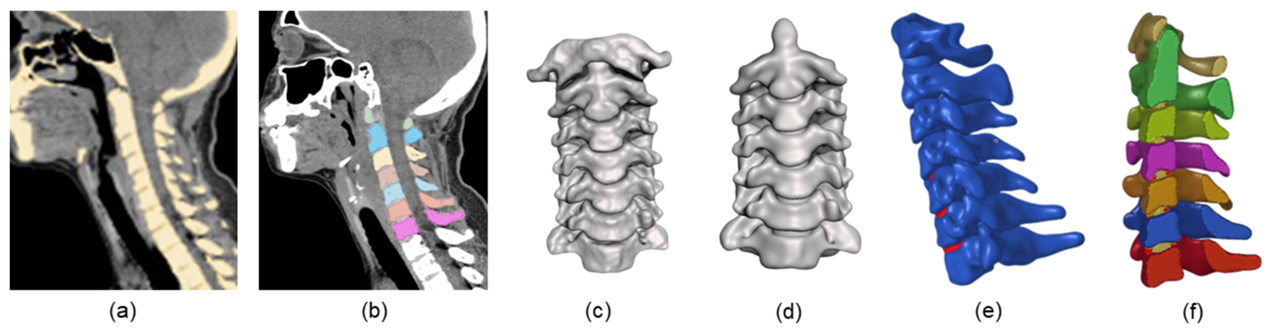
The initial geometric information of the model was obtained from CT scans of a 49-year-old female subject. These were in a DICOM format and were imported to open-source 3D Slicer software to conduct image segmentation. In this software, a brightness threshold was defined in order to highlight only the bony tissue, as the soft tissues are not visible in CT due to their lower density. At this point, both cortical and cancellous bone were considered as one material. This initial segmentation included the required sections as well as the rest of the skeletal parts of the CT scans. After removing the non-essential parts, only the C1 to C7 vertebrae remained. However, as these were combined in just one part, each vertebra was manually separated to obtain seven individual segments. The original orientation of the cervical spine was maintained throughout the whole process. This was to prevent the possibility of significant errors during simulation, as the CT scans showed the neck with a neutral posture.
The created segments were converted to STL files, which were then imported into MeshMixer (Autodesk, San Rafael, CA, USA). Geometrical inaccuracies such as holes and anatomically incorrect features were identified and rectified using this software. One of the most significant irregularities was found on the facet joints, as the articular surfaces were excessively close together. This can be attributed to the inclusion of denser soft tissues, such as the facet cartilages, during the definition of the brightness threshold in the previous step. As such, a clearance with an average facet distance [
18] was manually set on each vertebra.
Each vertebra was lightly smoothed to fix smaller irregularities in the geometry and to facilitate the solid meshing process without compromising the model’s global geometry. The next step was the creation of the intervertebral discs. The initial geometry was generated based on the upper and lower surfaces of each corresponding vertebrae and on anatomical descriptions from the literature [
19,
20].
2.2. Finite Element Modelling
In this step, the edited STL files were exported to Hypermesh (Altair, Troy, MI, USA) for mesh generation. When considering the types of elements to use when meshing the cervical spine, two are generally preferred, namely, tetrahedral and hexahedral elements. The first type facilitate mesh generation on the vertebrae’s curved surfaces, but are limited by the fact that they are more computationally expensive and can be excessively stiff [
21]. Hexahedral elements are generally preferred for 3D nonlinear analysis. However, they require more time during mesh generation, and if the surface smoothing is not performed proficiently it may cause edge discontinuities.
Because hexahedral elements can be beneficial if properly meshed, they were used to mesh most of the cervical components. When generating the mesh, two parameters were taken into consideration: the desired element size and the minimum Jacobian. The desired element size for the vertebrae was set to 0.6 mm, while the intervertebral discs were set to 0.5 mm. Different element sizes were tested; the values selected guaranteed the best convergence without compromising the overall CPU cost in subsequent simulations. The minimum Jacobian was set to 0.3 in all the components in order to ensure acceptable element aspect ratios.
Afterwards, the vertebrae were separated into two types of bones, namely, cortical and cancellous. In this work, the posterior elements of the vertebrae, for example, the spinous process, were not considered to be different types of bones and were not modelled as such [
12,
22]. The cortical bone, as the outer layers of the mesh on the vertebrae, was considered to achieve a thickness of approximately 0.5 mm, the average thickness found in the literature [
23].
The intervertebral discs were separated according to their different type of materials, these being the AF ground substance, the nucleus pulposus, and the cartilaginous endplates. It was decided that the AF fibers would not be included in order to simplify the first simulations of the cervical FEM [
16,
24,
25]. The endplates were modeled as the top and bottom layers of the intervertebral disc. The rest of the disc was divided into AF grounds (60%) and nucleus pulposus (40%) [
16].
The next step was the formulation of the facet joint. These were modeled by assigning contact integration properties to the superior and inferior articular cartilages. The cartilage geometry was generated based on anatomical descriptions from the literature [
26] and on the superior and inferior articular process surfaces (for the inferior and superior cartilages, respectively) of each corresponding vertebrae.
Most components were modeled with eight-node brick elements with reduced integration (C3D8R) with the exception of the facet cartilage, which was modeled with general purpose linear brick elements (C3D8), and the nucleus pulposus, where hybrid reduced integration hexahedral elements (C3D8RH) were used. In the first case reduced integration elements could not be used, as they perform poorly during contact, and the general-purpose elements showed the best results when simulating, while in the second case the hybrid formulation was used, because the software can only represent incompressible materials using these elements.
Figure 1 shows a summary of the methodology used to create the geometry and mesh of the cervical spine model.
Functional Spinal Unit Model
Considering that the complete model (without the ligaments) consisted of 655,924 elements and 740,471 nodes, a full simulation would take a significant amount of time. As seen in previous studies, it is possible to first analyze a section of the spine before simulating the entire model, or even to simulate the entire model by dividing it into segments. Maurel et al. [
10] created a complete model of the lower cervical spine (LCS) while first testing a reduced FSU comprised of the C4–C5 segment before simulating the complete model. Kallemeyn et al. [
17] started by modeling the C4–C5 FSU and validating it before creating a new more completed (C2–C7) model in [
11]; furthermore, this model was calibrated by subdividing it into single FSUs (C2–C3, C4–C5, and C6–C7). Later, Östh et al. [
12] created and validated a C0–T1 cervical FEM by simulating segments of the model, one of the upper cervical spine (UCS) and six of the LCS.
Thus, it was decided that the model would be validated by initially simulating and validating an FSU consisting of two vertebrae, and the complete model would be validated in a future work. For this study, the C6–C7 segment was selected, resulting in a smaller model consisting of 239,381 nodes, 718,143 DOF.
Considering that the selected FSU is located in the LCS, only five ligaments were considered. These were the anterior longitudinal ligament (ALL), posterior longitudinal ligament (PLL), capsular ligament (CL), ligamentum flavum (LF), and interspinous ligament (ISL). The intertransverse ligament was not modeled, as it often blends with the intertransverse muscles [
13]. Furthermore, the supraspinous ligament (SSL) was not explicitly modeled, because in many anatomical studies it is difficult to distinguish it from the ISL. Therefore, it was considered to be aggregated with the ISL in the model [
17]. The number of the elements for the ALL, PLL, ISL, LF, and CL were 5, 5, 5, 6, and 16, respectively [
16,
27]. These were modelled using truss elements (T3D2) working in tension only. It is worth nothing that, apart from the CL surrounding the facet cartilages, the placement of the ligaments was based on anatomical descriptions [
28]. Furthermore, each ligament element was assigned a cross-sectional area, with that the total ligament area representing values from the literature [
29].
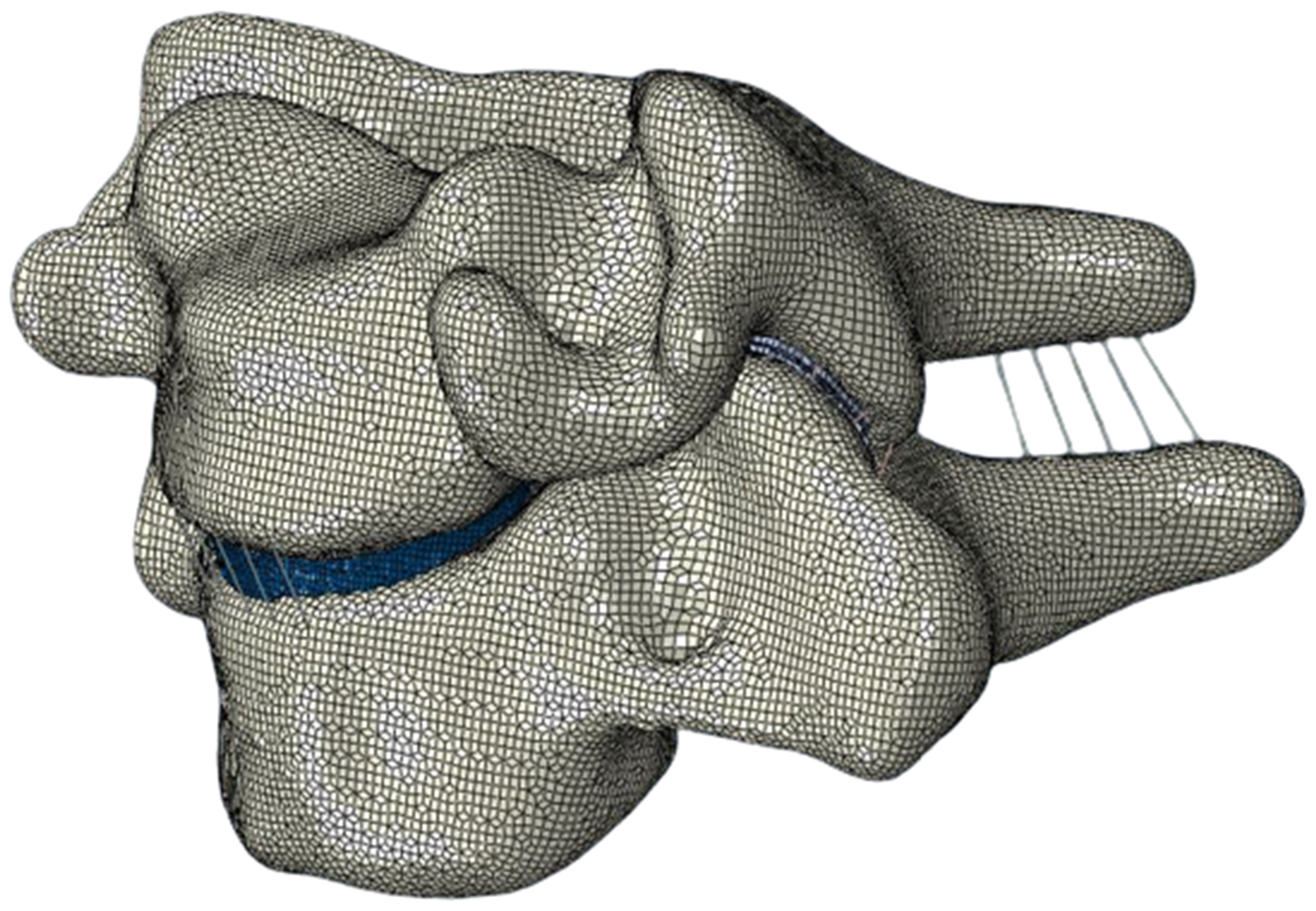
Lastly, the model was imported to Abaqus (Simula, USA) to perform the simulations. In the end, the FSU model (as seen in
Figure 2) had a total of 216,540 elements and 243,756 nodes.
2.3. Material Properties
The material properties were set based on the previously published literature. In this work, all the components were assumed to be isotropic materials with linear elastic properties in order to simplify the first simulations. Additionally, all ligaments were set to the “no compression” option provided in the software used to simulate the model to ensure that they would work only in tension. Finally, a density was assigned to each component. The material properties can be found in
Table 1.
Table 1.
Material properties used for the cervical spine model.
Table 1.
Material properties used for the cervical spine model.
| | Components | Young Modulus (MPa) | Poisson’s Ratio | Density (kg/mm3) | Cross-Sectional Area (mm2) | References |
|---|
| Vertebra | Cortical bone | 10,000.0 | 0.30 | 1.83 × 10⁻⁶ | - | [14,22] |
| Cancellous bone | 450.0 | 0.25 | 1.00 × 10⁻⁶ | - | [14,30] |
| Facet Joint | Cartilage | 10.0 | 0.40 | 1.10 × 10⁻⁶ | - | [16,31] |
| Intervertebral disc | Nucleus pulposus | 1.0 | 0.48 | 1.36 × 10⁻⁶ | - | [14,30] |
| AF ground substance | 3.4 | 0.40 | 1.20 × 10⁻⁶ | - | [30,32] |
| Endplate | 5.0 | 0.40 | 1.06 × 10⁻⁶ | - | [15,22] |
| Ligaments | ALL | 30.0 | 0.30 | 1.00 × 10⁻⁶ | 12.5 | [22,33] |
| PLL | 20.0 | 0.30 | 1.00 × 10⁻⁶ | 8.0 | [22,33] |
| CL | 7.7 | 0.30 | 1.00 × 10⁻⁶ | 37.3 | [22] |
| LF | 1.5 | 0.30 | 1.00 × 10⁻⁶ | 41.0 | [22,33] |
| ISL | 1.5 | 0.30 | 1.00 × 10⁻⁶ | 14.9 | [22,33] |
As for interactions, all ligaments and endplates of the intervertebral disc were tied to the vertebrae, whereas the facet joints were modeled using surface-to-surface contact with a friction coefficient of 0.05 between the cartilages [
32].
2.4. Boundary and Loading Conditions
Appropriate boundary and loading conditions must be provided to accurately simulate the cervical spine throughout its primary movements, such as flexion, extension, lateral bending, and axial rotation. These were chosen to resemble as closely as possible those of experimental studies in which the cervical spine’s ROM was assessed.
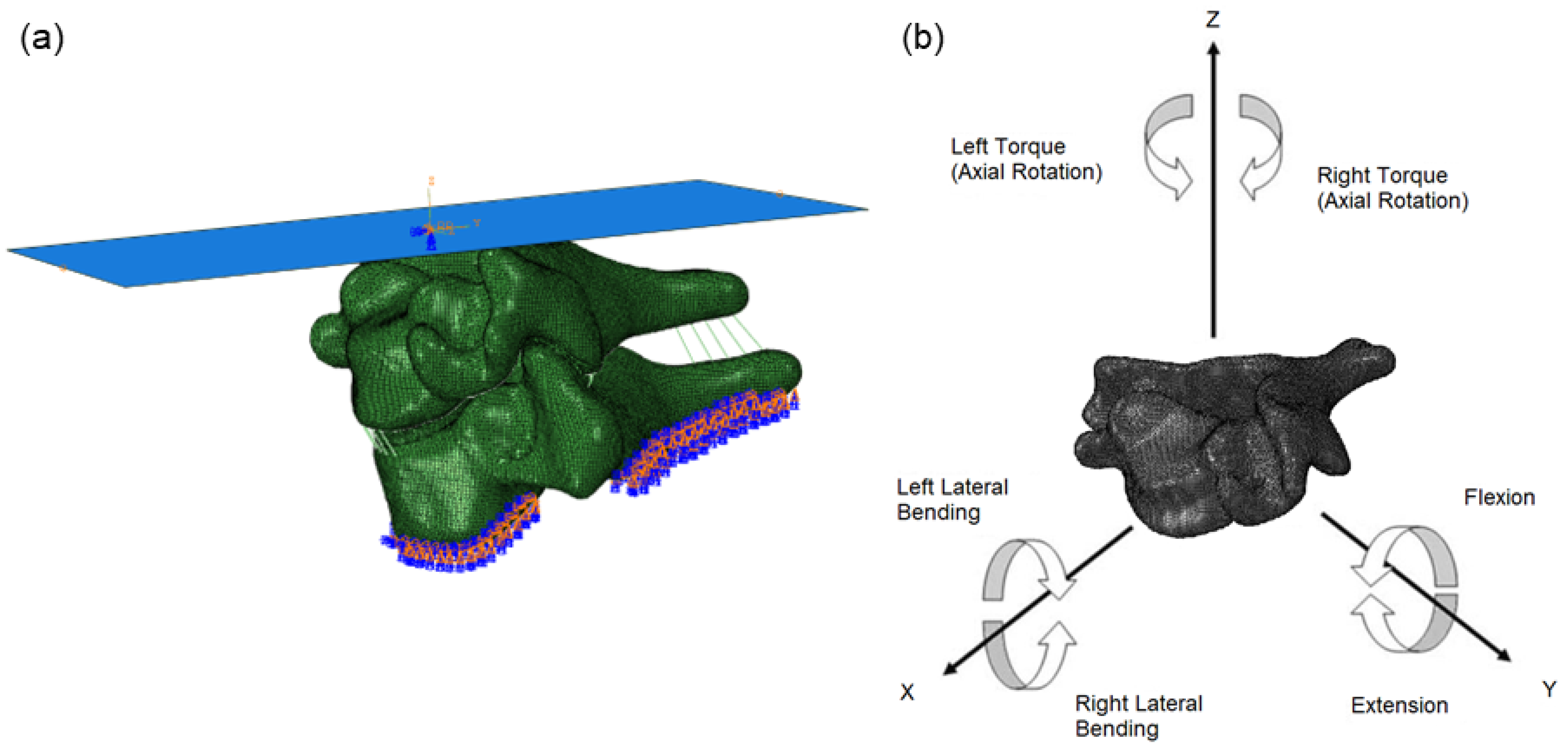
For boundary condition (
Figure 3a), because it is generally considered that the segment is supported rigidly along the bottom portion or endplate of the end vertebra, the lower surface of the bottom-most vertebra was restricted in all degrees of freedom. As for the loading conditions (
Figure 3b), in other FEMs the loads are usually applied on a single point of the superior surface of the top vertebral body or on a centroid point of the uppermost vertebra. However, in this model, all loads were applied using a rigid surface rather than a single point, preventing any distortion that might result from an uneven distribution of force. The rigid surface was fixed to the superior part of the C6 vertebra. A more detailed explanation of the boundary conditions can be found in
Table 2.
2.5. Model Validation
The selection of the experimental studies to perform the validations was based on commonly used tests in the literature. Several of these studies used linear forces to study the kinematics of the cervical spine; however switching to pure moments of rotation allows for better control of the applied forces, and therefore leads to more accurate results [
34]. Therefore, the experiments performed by Nightingale et al. [
35] and Panjabi et al. [
34] were chosen. These in vitro experiments are fairly similar, varying only in the samples used, the mechanism employed, and, most importantly the total and deliverance of the moments applied.
The methodology used was similar in both experiments, and consisted of first removing the muscular tissues of the spinal segments while keeping the ligament structures intact, then securing the bottom portion of each segment to restrict any movement while the mechanism applied the moments to the upper most vertebrae. Nightingale et al. [
35] used pure flexion and extension moments in increments of 0.5 Nm until a peak load of 3.5 Nm was reached. This load was 10–15% of the failure load, in order to preserve the integrity of the sample. In Panjabi et al. [
34], the segments were subjected to pure moments applied in flexion, extension, axial rotation, and lateral bending. Each moment was divided into three equal load increments totaling 1 Nm. This value was selected because it was considered to be sufficient to produce physiologic motion but small enough not to adversely affect the sample.
These studies had one major limitation, namely, sample preparation that involved the removal of muscles without affecting ligaments or bone. There is a possibility that the ligament attachments could have been affected during the process of removing the muscles, as these are both connected to each other and bonded to the bones in several locations.
3. Results
The FSU was subjected to six moments of pure moments of 1 Nm working in flexion, extension, axial rotation, and lateral bending. Throughout the application of the loads, the range of motion (ROM) was monitored using a reference point (RP) located on the center of the previously created rigid surface. All simulations were performed using “Dynamic Implicit” analysis.
The accuracy of the developed model was validated by comparing output predictions with previously published experimental data. The results for flexion and extension were compared with the studies from Nightingale et al. [
35] and Panjabi et al. [
34]; the results for axial rotation and lateral bending were compared only with the study from Panjabi et al. [
34].
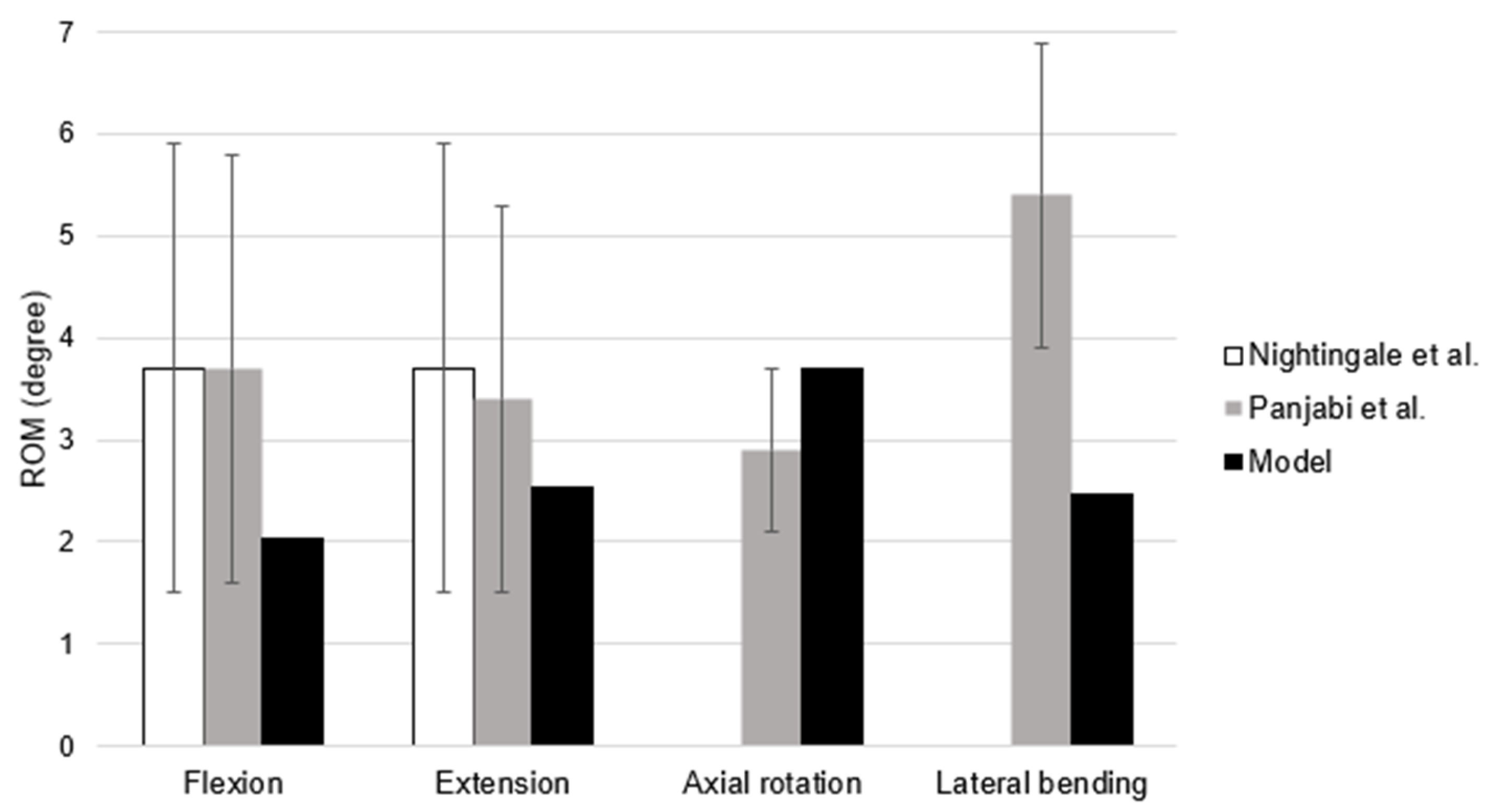
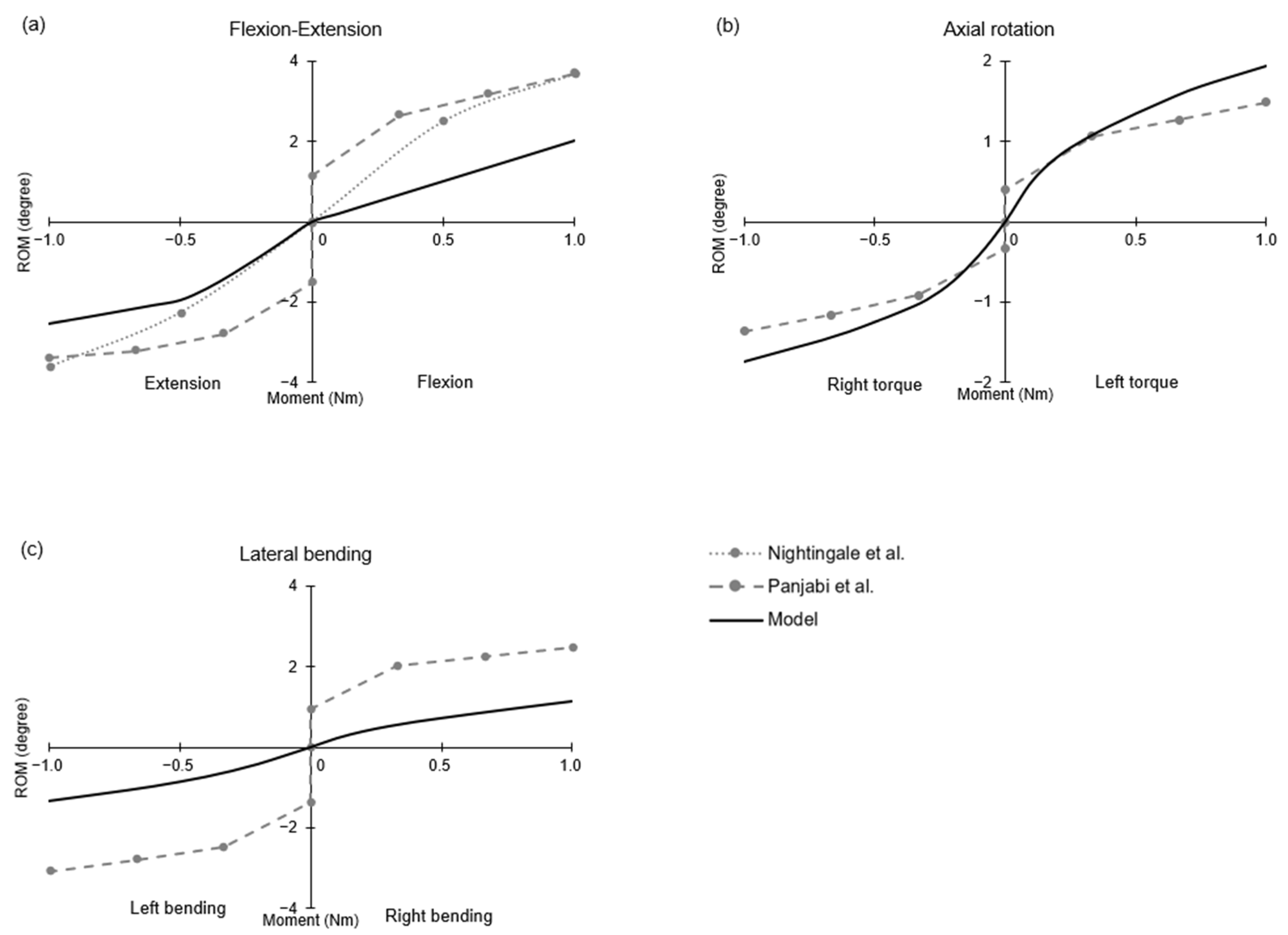
Figure 4 shows that the results of the simulations fell within the experimental corridor of the selected in vitro studies. During flexion, the model registered an ROM of 2.03°, where the literature shows values of 3.7° ± 2.2 [
35] and 3.7° ± 2.1 [
34]. For extension, 2.53° was recorded, while the in vitro tests reported 3.7° ± 2.2 [
35] and 3.4° ± 1.9 [
34]. These results are consistent with the literature, indicating that the FEM of the C6–C7 segment was validated in terms of both flexion and extension. The FSU showed 1.95° in left rotation and 1.75° in right rotation, for a total of 3.70°, while Panjabi et al. [
34] reported 2.9° ± 0.8. As such, although the simulation values are near the upper bound of the range provided by the experimental study, they are nonetheless consistent with them, validating the axial rotation. Lastly, for lateral bending the registered ROM was 2.46° (1.14° in right bending and 1.32° in left bending). This is the only test that shows results outside of the experimental range; the study by Panjabi et al. [
34] reported that the C6–C7 segment had a lateral bending rotation of 5.4° ± 1.5. As such, the FSU results are somewhat lower than the expected values.
4. Discussion
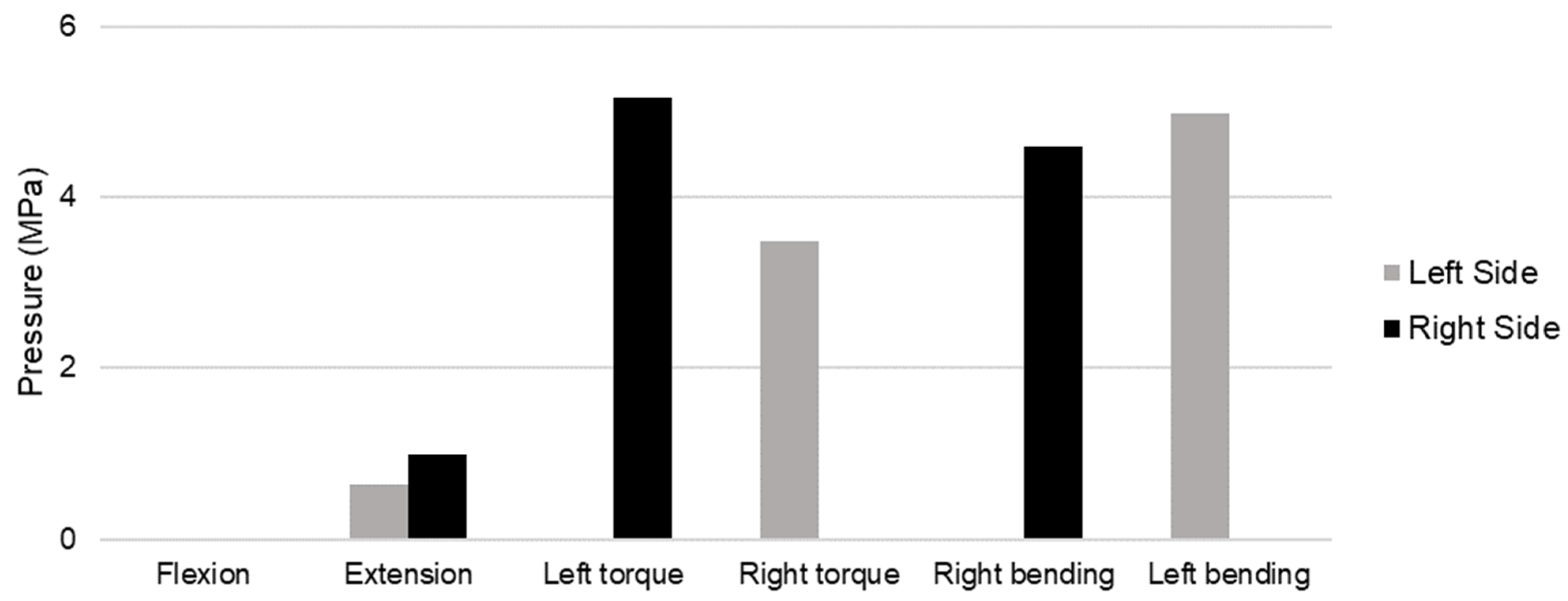
From the above analysis of the simulation results, it is possible to observe that the ligaments and facet joints play a major role in limiting movement, as was expected. Furthermore, the role of the facet joints in limiting the ROM is more pronounced in axial rotation and lateral bending, as evidenced by the higher pressures registered during these movements (
Figure 5).
Furthermore, it was possible to analyze the internal response to external loading of other cervical components, such as the intervertebral discs. Lastly, additional comparisons between the model behavior and the experimental data were performed. A description of each test result is provided below.
4.1. Flexion and Extension Test
For the first simulation, the model was subjected to two pure moments of 1 Nm applied in flexion (positive moment) and extension (negative moment).
Figure 6a shows the comparison between the results obtained from the FEM and those recorded in the in vitro tests. During extension, the behavior of the model was similar to the experimental model; however, in flexion the model assumed a linear behavior. This may be a result of the linear elastic properties of the ligaments, as they are the main components that restrict motion during flexion.
Output predictions were as expected, with the uppermost vertebral body leaning forward during flexion and backward during extension. During forward motion the vertebral body rotates, causing compression on the anterior edge of the intervertebral disc. As a result, stress is concentrated on the anterior region of the disc. The same occurs during extension, except that the compressive force instead affects the posterior edge, causing concentrated stress on the posterior region of the disc.
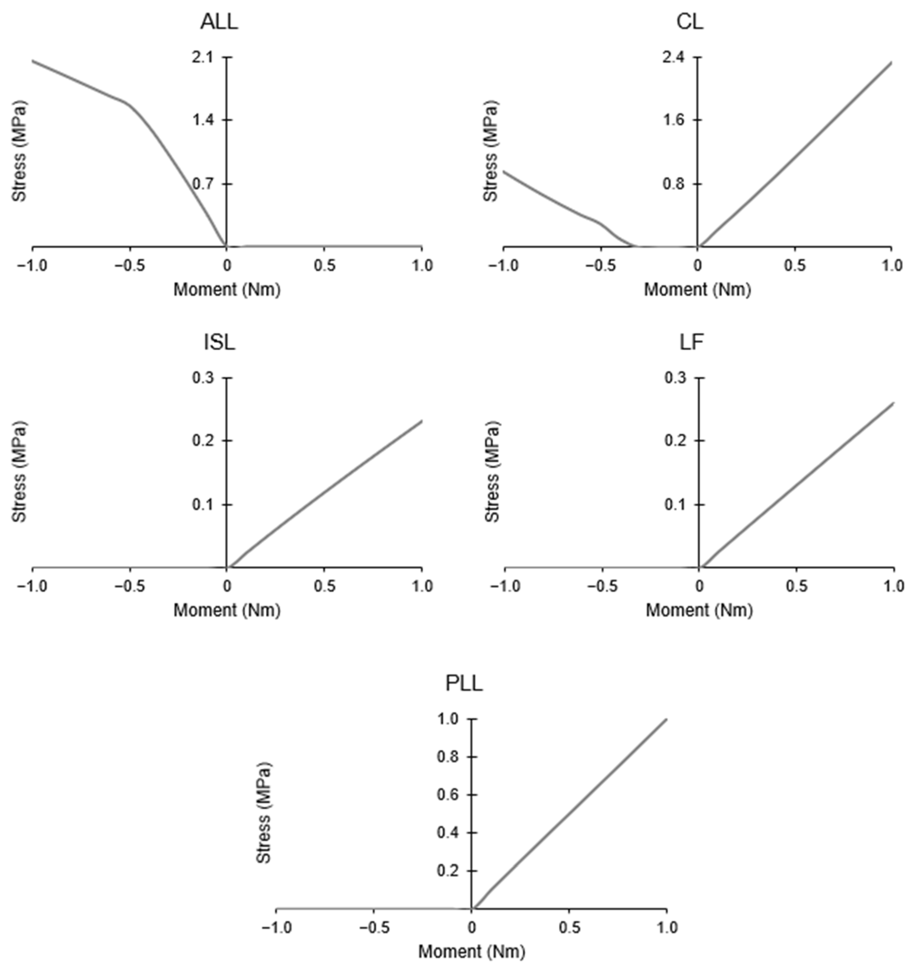
The ligaments are fundamental in the definition of the cervical spine’s ROM. They act primarily in tension, and as such develop stresses when stretched, which varies according to the moment applied. Therefore, certain ligaments contribute more to withstanding certain loads because of their location. The ALL is one example; it is not active during flexion, and produces stress during extension. The opposite occurs in the PLL, ISL, and LF, while the CL is active during both motions.
Figure 7 shows the maximum stress registered by the ligaments during flexion–extension.
Likewise, the facet joints play an important role in the movement of the cervical spine by restricting actions depending on their level [
36]. After analyzing the results, it is possible to observe that there was no contact between the facet cartilages during flexion, while the opposite was the case during extension. The second scenario shows the larger role of the facet joints in restricting spinal movement, as there are fewer ligaments active in extension. Moreover, the nonlinear behavior of the model in most movements may be due to the facet joints, considering that during flexion there is no contact and the model behaves linearly, while in extension, when contact is registered, the model starts to show nonlinearity. It can be speculated that in the case of extension the contact between cartilages is registered when the applied load reaches 0.5 Nm, as the behavior curve of the model changes when this moment is reached.
4.2. Axial Rotation Test
In the comparison of results, the model and the in vitro experiment produce similar outcomes (
Figure 6b) when two pure moments of 1 Nm are applied along the transverse plane. Even though the results of the simulated FSU are higher than the mean experimental values, they are within the standard deviation.
When axial torque is applied, either left (positive direction) or right (negative direction), the entire upper vertebra rotates in the direction of the moment. Consequently, in the intervertebral disc, compression is present on the side of the applied moment and traction on the other. As for the facet joints, as the spine rotates, one of the two pairs is activated; one restricts movement, while the other moves the cartilages apart. More pressure was observed on the right facet joint compared to the left. This can be attributed to the asymmetry of the spine or to the original orientation of the cervical spine.
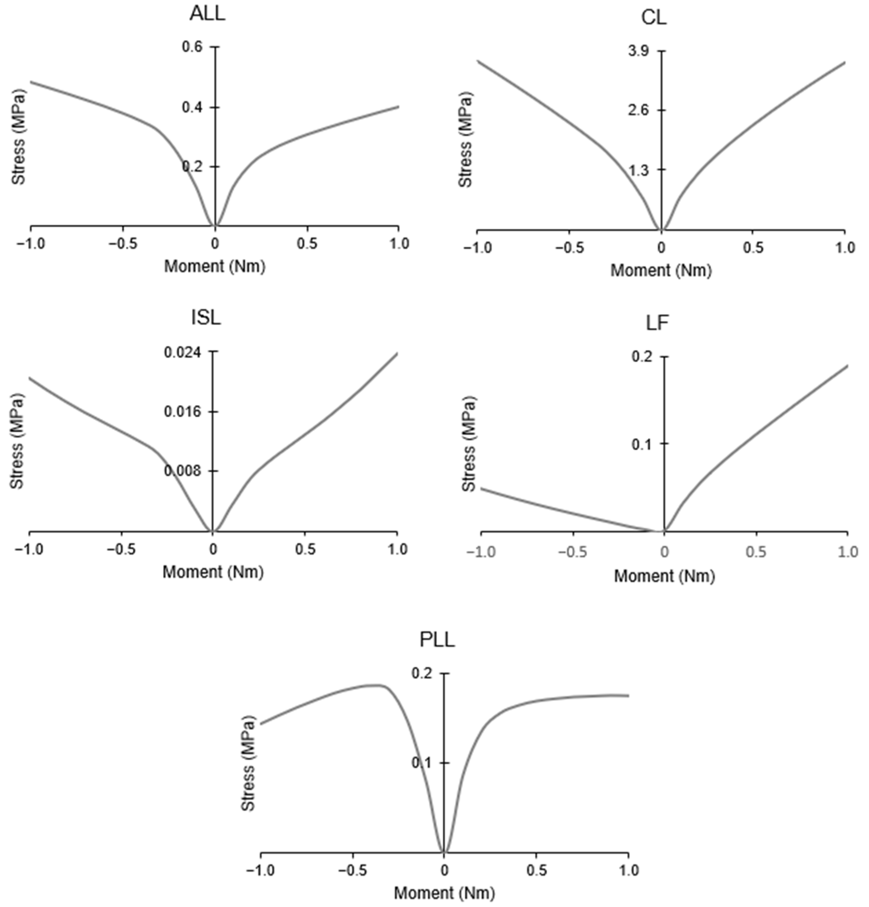
In axial rotation, all ligaments are activated regardless of rotation direction. This can be seen in
Figure 8, where they all produce stress with either left or right torque. For the most part, the ligaments respond symmetrically to axial rotation, with the exception of the LF, which shows lower stress with right torque. This may be a result of the placement of the ligament or the original orientation of the spine.
4.3. Lateral Bending Test
The final test conducted on the model was lateral bending. The left (negative direction) and right (positive direction) bending of the FSU resulted from the use of two moments of 1 Nm each. As seen in
Figure 6c, the behavior of the model is fairly similar to the experimental one, although the simulated ROM is stiffer and shows values lower than the standard deviation. There are several possible reasons for this situation, including ligament positioning, the original orientation of the spine, linear elastic properties of the ligaments, and misalignment between the applied moment and the vertebrae.
Nevertheless, the uppermost vertebra bends either right or left based on the applied moment, as expected. As in the previous cases, when the vertebra moves, the vertebral body rotates and compresses a region of the intervertebral disc, while the other region undergoes traction. As the model leans sideways, the disc shows a concentration of stress on the corresponding side.
Similar to axial rotation, a single facet joint is activated during this movement. Unlike axial rotation, however, the active joint is on the same side of the applied load direction. When the spine moves to one side, the ligaments are stretched on the opposite side. In this case, the ligaments are split almost symmetrically in the middle through the sagittal plane. As a result, half of a ligament is active and the other half is inactive during the same movement.
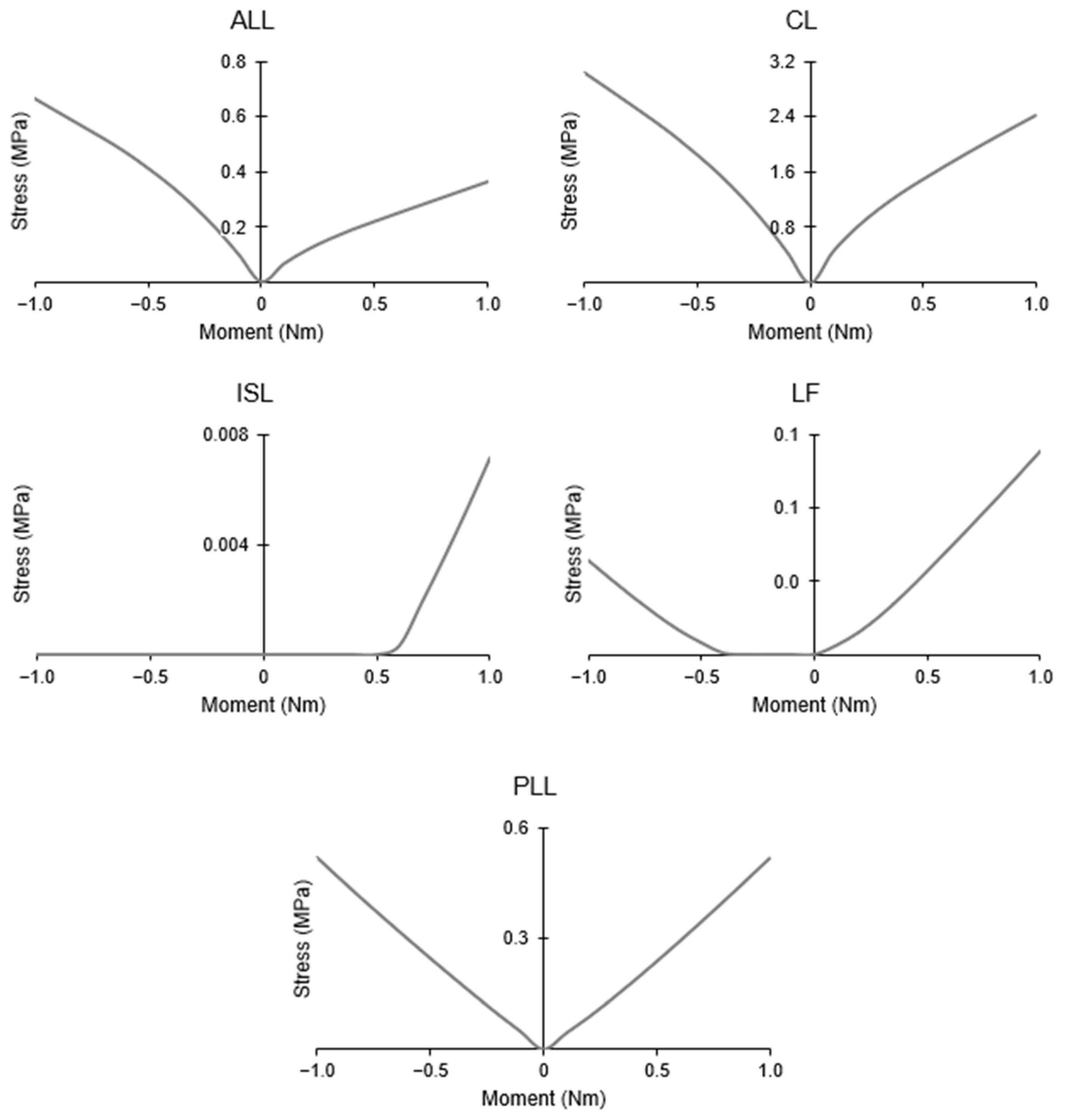
Figure 9 does not show this peculiarity, as it only shows the maximum stress recorded on the ligaments; however it shows that they respond symmetrically to lateral bending. The ISL is the sole exception; it is not active during these movements, as it is aligned with the sagittal plane. However, a small stress was found on the model during right bending. This is either due to the original orientation of the spine, ligament positioning, or a misalignment between the applied moment and the vertebra.
It is important to point out that the same stiffness in the C6–C7 segment is present in other FEMs, including those that use the experiments of Panjabi et al. [
34] to validate their work. Additionally, comparison of the FEM with previously validated models has been performed before. In Toosizadeh and Haghpanahi [
13], the model was validated against data obtained from several in vitro tests, then compared with the results obtained from the FEM of Zhang et al. [
33]. The model created by Erbulut et al. [
14] was set against the studies from Panzer et al. [
37] and Zhang et al. [
33]. Later, Östh et al. [
12] compared their model with Panzer et al. [
37] as well as those created by Fice and Cronin [
38] and Cronin [
39]. As such, a comparison of the simulated FSU with other FEMs [
14,
32,
33,
40] was preformed, with the results shown in
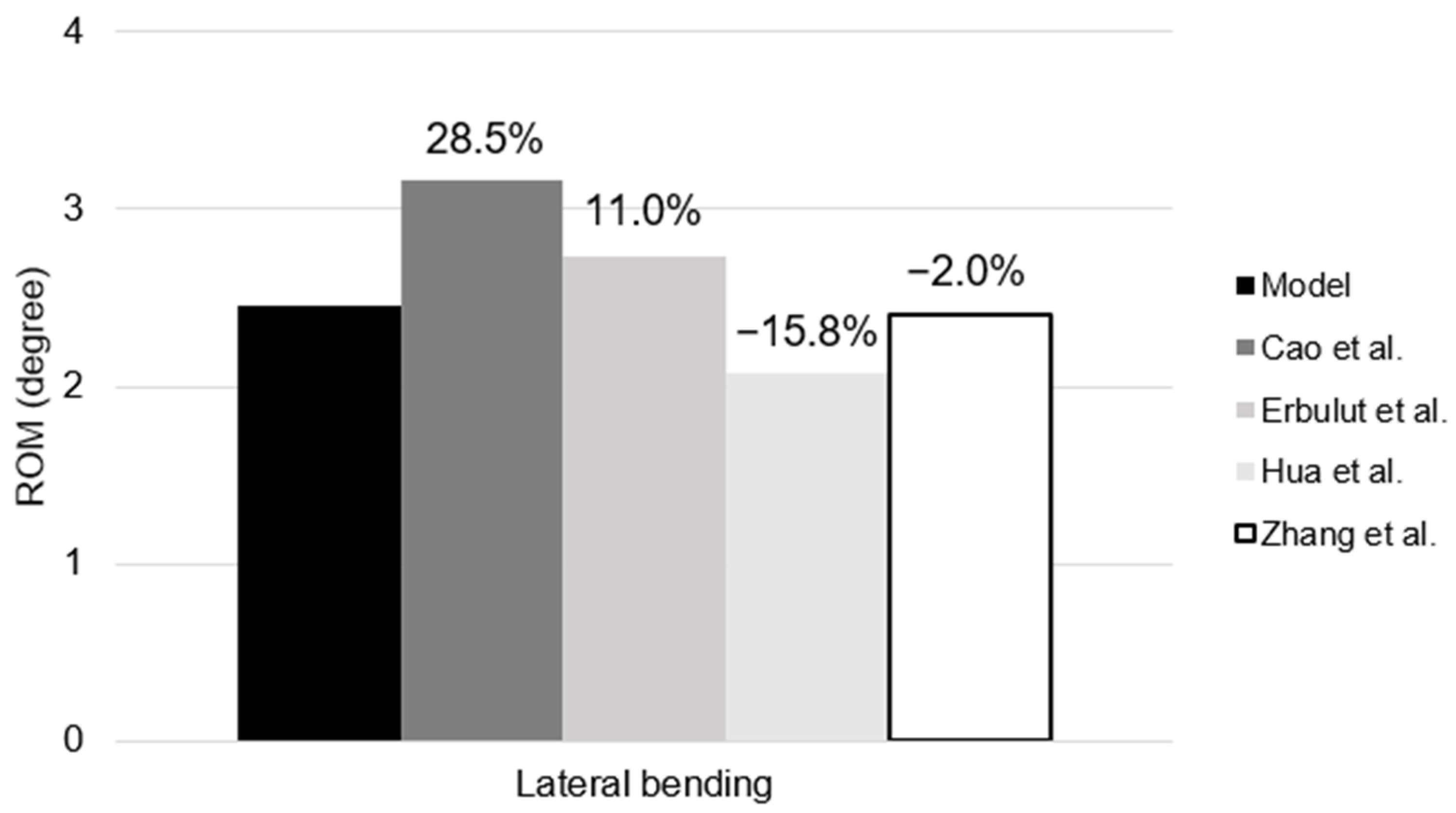
Figure 10. The results of the comparative analysis reveal that they all produce similar outcomes, with the largest deviation being 28.5% and the smallest being 2.0%.
5. Conclusions
The aim of this work was the creation of a detailed 3D model of the human neck and the preliminary validation process. To this end, a review of the current literature was conducted in order to understand what had been done previously and how to approach the methodology in this type of work. Six different moments were applied in flexion–extension, axial rotation, and lateral bending to the selected FSU model for the purpose of validating it against data obtained in experimental results.
Even though the lateral bending results were not as satisfactory as in other tests, they were similar to the values obtained in previously validated FE models. Thus, it can be concluded that the selected model accurately portrays the desired segment of the cervical spine.
It is possible to conclude that the combination of parametric studies and precise reconstruction is a viable method to create new FEMs of the cervical spine; ideally, MRI should be added in a future work to create certain components, as this will result in a more bio-realistic model.
Despite the model accurately representing the chosen segment, several limitations were found that should be addressed in subsequent research. The AF fibers have a role in limiting ROM, and were not represented. This exclusion may have been a contributing factor to the discrepancy between the experimental and simulation results. Contrary to previous FEMs of the spine, the intervertebral discs were not modeled with a concentric mesh, which could have had an influence on the final results, although this is uncertain. While easy to implement, isotropic materials with linear elastic properties do not accurately portray the behavior of the different materials that comprise the cervical components. A few geometrical divergences occurred due to the meshing algorithm, resulting in distorted elements, which may have led to an increase in simulation run times. Moreover, extra stiffness could have been related to ligament positioning, the original orientation of the spine, the linear elastic properties of the ligaments, or misalignment between the applied moment and the vertebrae, as mentioned previously.
The next step in our research will be the conclusion of the validation process, the addition of more realistic material behavior for most of the components, and the modelling of the muscular system. Additionally, we expect to couple of the created model with an FEM of the head in order to more accurately study head–neck kinematics and whiplash-related pathologies.


 ,
, 


