Article

Finite Element Analysis of Energy-Absorbing Floors for Reducing Head Injury Risk during Fall Accidents

Division of Neuronic Engineering, KTH Royal Institute of Technology, 14152 Stockholm, Sweden
*
Author to whom correspondence should be addressed.
Appl. Sci. 2023, 13(24), 13260; https://doi.org/10.3390/app132413260
Submission received: 25 October 2023 / Revised: 2 December 2023 / Accepted: 12 December 2023 / Published: 14 December 2023

Abstract

:

Featured Application

The results proposed a new approach to evaluate the protection effectiveness of energy-absorbing floors for fall-related injury prevention. Also, it could help to reduce the huge associated costs related to fall-related injuries among the children and elderly population.

Abstract

Energy-absorbing floor (EAF) has been proposed as one of several biomechanically effective strategies to mitigate the risk of fall-related injuries by decreasing peak loads and enhancing system energy absorption. This study aims to compare the protective capacity of four commercially available EAF products (Igelkott Floor, Kradal, SmartCells, and OmniSports) in terms of head impacts using the finite element (FE) method. The stress–strain curves acquired from mechanical tests were applied to material models in LS-Dyna. The established FE models were then validated using Hybrid III or hemispheric drop tests to compare the acceleration–time curves between experiments and simulations. Finally, the validated FE models were utilized to simulate a typical pedestrian fall accident scenario. It was demonstrated that EAFs can substantially reduce the peak forces, acceleration, and velocity changes during fall-related head impacts. Specifically, in the accident reconstruction scenario, SmartCells provided the largest reduction in peak linear acceleration and skull fracture risk, while Igelkott Floor provided the largest reduction in peak angular velocity and concussion risk. This performance was caused by different energy absorption mechanisms. Consequently, the results can contribute to supporting the implementation of EAFs and determine the effectiveness of various protective strategies for fall-related head injury prevention.

1. Introduction

Fall-related injuries among the elderly and children are an enormous health concern worldwide [1]. For seniors over the age of 65, especially in high-risk environments such as long-term care, around 60% of elders fall at least once per year [2], which can cause injuries including hip fracture [3] and traumatic brain injury (TBI) [4]. Similarly, the annual average number of emergency department visits for adolescents under 14 years old in the United States exceeded 200,000, with 9.8% having a TBI due to falls from 2001 to 2013 [5]. Considering the alarming rise in incidence and fatality rates of fall-related TBI [6,7], it is imperative to design and implement effective intervention strategies to contain the social and economic impact of the prospective increase in fall-related TBI incidence over the coming decades [8].
Currently, a common approach that is particularly relevant for high-fall-risk environments is to reduce the stiffness of the ground surface in order to attenuate the contact forces applied to the body during a fall impact [9,10]. An energy-absorbing floor (EAF) is a passive intervention structure with the intention of reducing the incidence and severity of fall-related injuries [11]. Evidence shows that some low stiffness surfaces like soft foam could influence balance maintenance and balance recovery abilities and cause a rise in fall risk [12]. Thus, EAF is generally designed to achieve a dual stiffness response characterized by minimizing deformation during movements and enhancing the energy absorption at the higher loads associated with fall-related impacts [13] without increasing the fall risk. A typical design pattern consists of a continuous top surface that overlays a series of support columns, which deform after reaching a critical load threshold.
Previous studies have suggested that certain commercially available EAFs could potentially reduce the risk of injury among the elderly without increasing the likelihood of falls based on statistics from incident reports [14]. Wright and Laing [13] investigated the flooring system on headform impact dynamics based on a mechanical drop tower and indicated that EAFs (SmartCells, SofTile, and Kradal) provided more protection than commercial carpet with a 20–80% reduction in impact force and an approximately 60–70% attenuation in HIC. Certain models of products have also exhibited a reduction in the femur impact force by up to 50% based on hip impact simulator tests [11] without substantially impairing balance in older women. However, there is a lack of biomechanical research concerning the impact process of pedestrian falls, as well as the absence of quantitative evaluation methods for the protective effectiveness of floor strategies. There is a need to conduct a detailed simulation analysis of impact dynamics at the human tissue level for the improvement of injury prevention strategies and corresponding protection effectiveness.
Finite element (FE) models and instrumented headforms have been increasingly used to investigate head impact dynamics and optimize the performance of safety gears, including ground surfaces [15]. The advantage of an FE head model is that it can be modeled in detail to investigate the effect on brain tissue level [16] and can match the anthropometric characteristics of human heads [12]. Various FE brain models have been developed for brain injury research, all with varying levels of anatomical detail, material properties, and boundary conditions between different anatomical regions of the brain [17,18,19,20]. Giudice et al. [21] presented a comprehensive summary of most of these models, such as the Global Human Body Model Consortium (GHBMC) [22], Imperial College model (IC) [23], KTH model [24], PIPER 18-year-old model [25], Total Human Model for Safety (THUMS) [26], etc. Previous research suggested that the intracranial responses could be different depending on which FE model is used [27]. The FE head model used in this study was previously developed at the Royal Institute of Technology (KTH) by Kleiven [24] using LS-DYNA. It includes the scalp, skull, brain, meninges (i.e., dura mater and pia mater), intracranial membranes, cerebrospinal fluid (CSF), eleven pairs of the largest parasagittal bridging veins, and a simplified neck with the extension of the spinal cord. The brain elements were further grouped to represent the primary brain components, including the cerebral gray matter (GM), cerebral WM, corpus callosum, thalamus, brainstem, midbrain, cerebellar GM, cerebellar WM, ventricles. Responses of this model have shown a good correlation with experiments on brain-skull relative motion [28], intracranial pressure [29], skull fracture [30], and brain strain [31].
Conventionally, head impact kinematics are usually investigated with an isolated head in simulations to save computational time. This approach is also common in physical testing to reduce complexity. Although employing a full-body model can represent more realistic boundary conditions during impacts, leading to more reliable predictions compared to an isolated head model, its applicability is challenged due to the high computational costs involved [25]. In this study, a Hybrid III (HIII) 50th percentile headform was also used in FE simulations and drop tests for validation.
The effect of the protective properties, such as strain attenuation in brain tissue, kinematics alteration of the head gravity center, and energy absorption during impact, has not yet been evaluated for various EAFs. Therefore, the aims of the current study are (1) to establish FE models to describe the mechanical properties of four EAFs, (2) to develop and validate the FE models against drop tests, and (3) to compare the protective capability of different EAFs using kinematic-based criteria and tissue-based criteria in a pedestrian fall accident.

2. Materials and Methods

To determine the material properties of each EAF, mechanical tests encompassing compression and tension were performed on the respective specimens. The stress–strain curves obtained from these tests were subsequently employed to construct material models for each EAF in LS-Dyna. The validation of the FE models was conducted through drop tests with an HIII head or a hemispheric impactor. By comparing the acceleration–time curves extracted from both experiments and simulations within identical initial conditions, the FE models were validated and further utilized to predict the risk of injury in a pedestrian fall scenario.

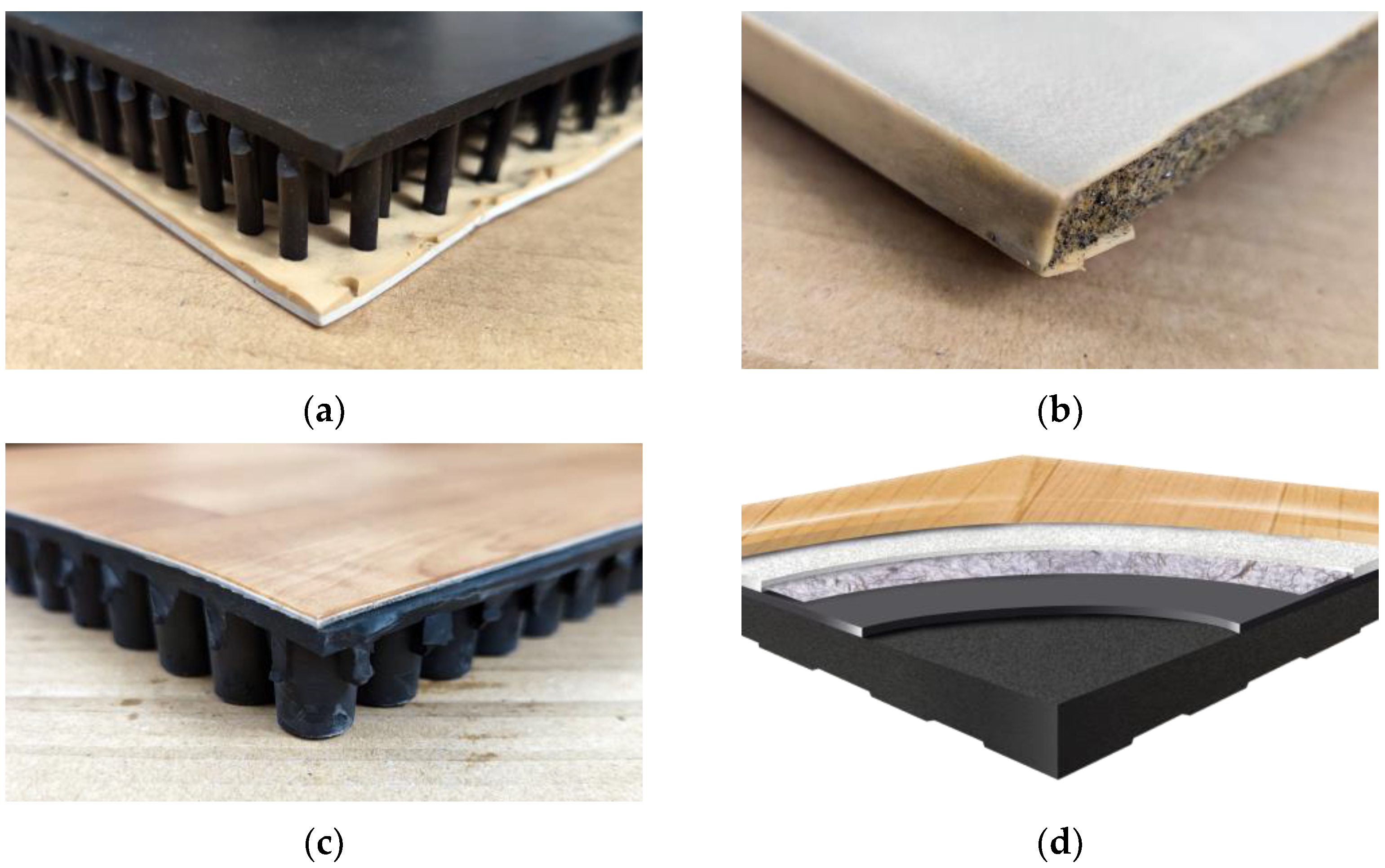
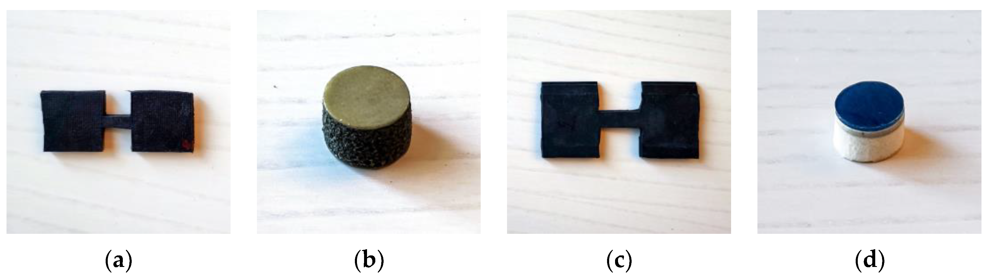
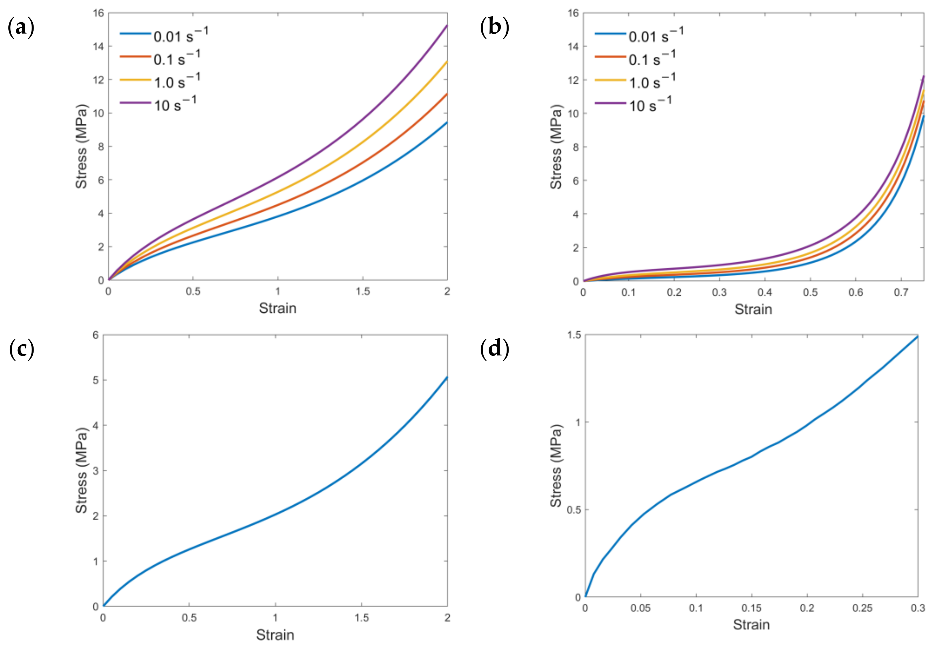
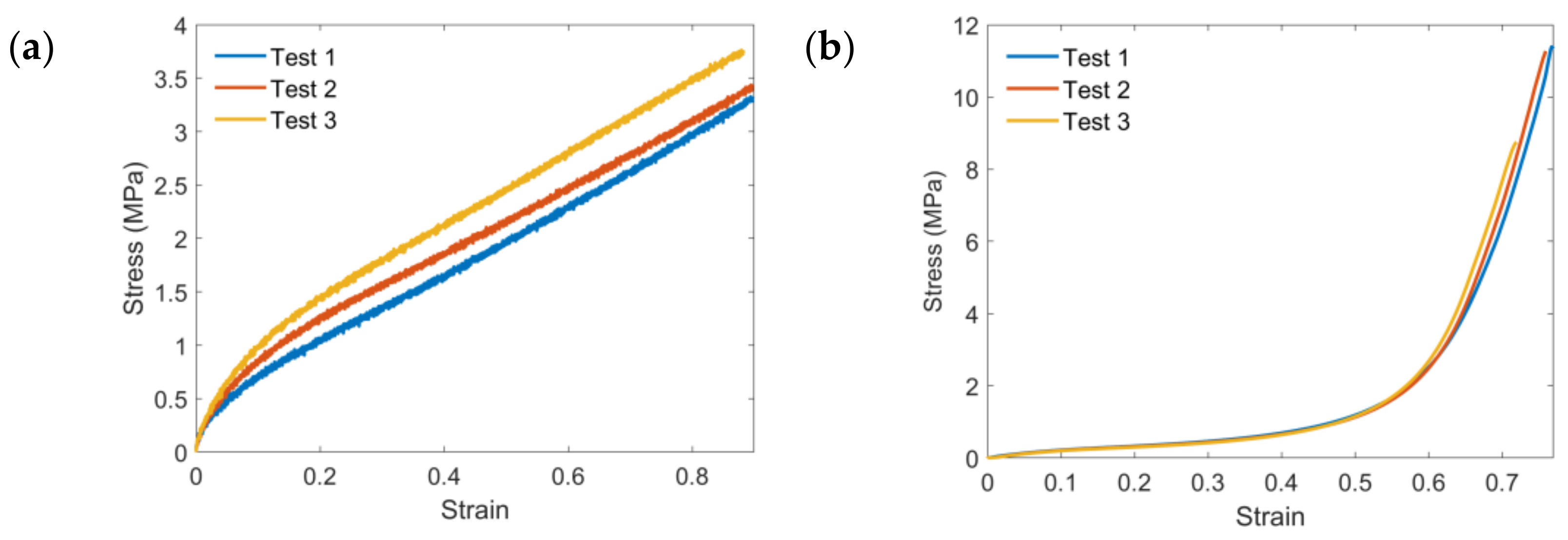
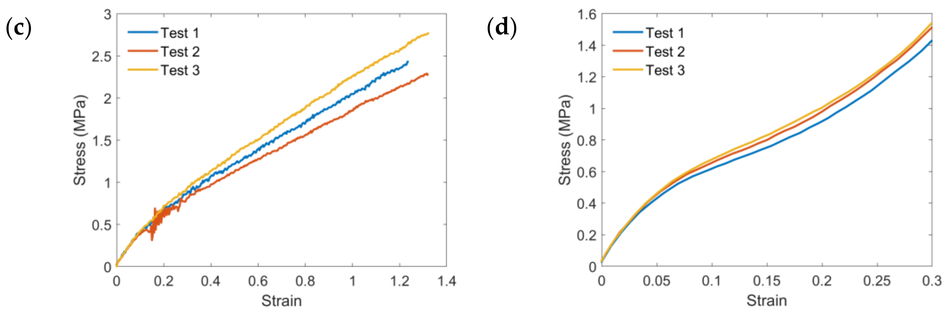
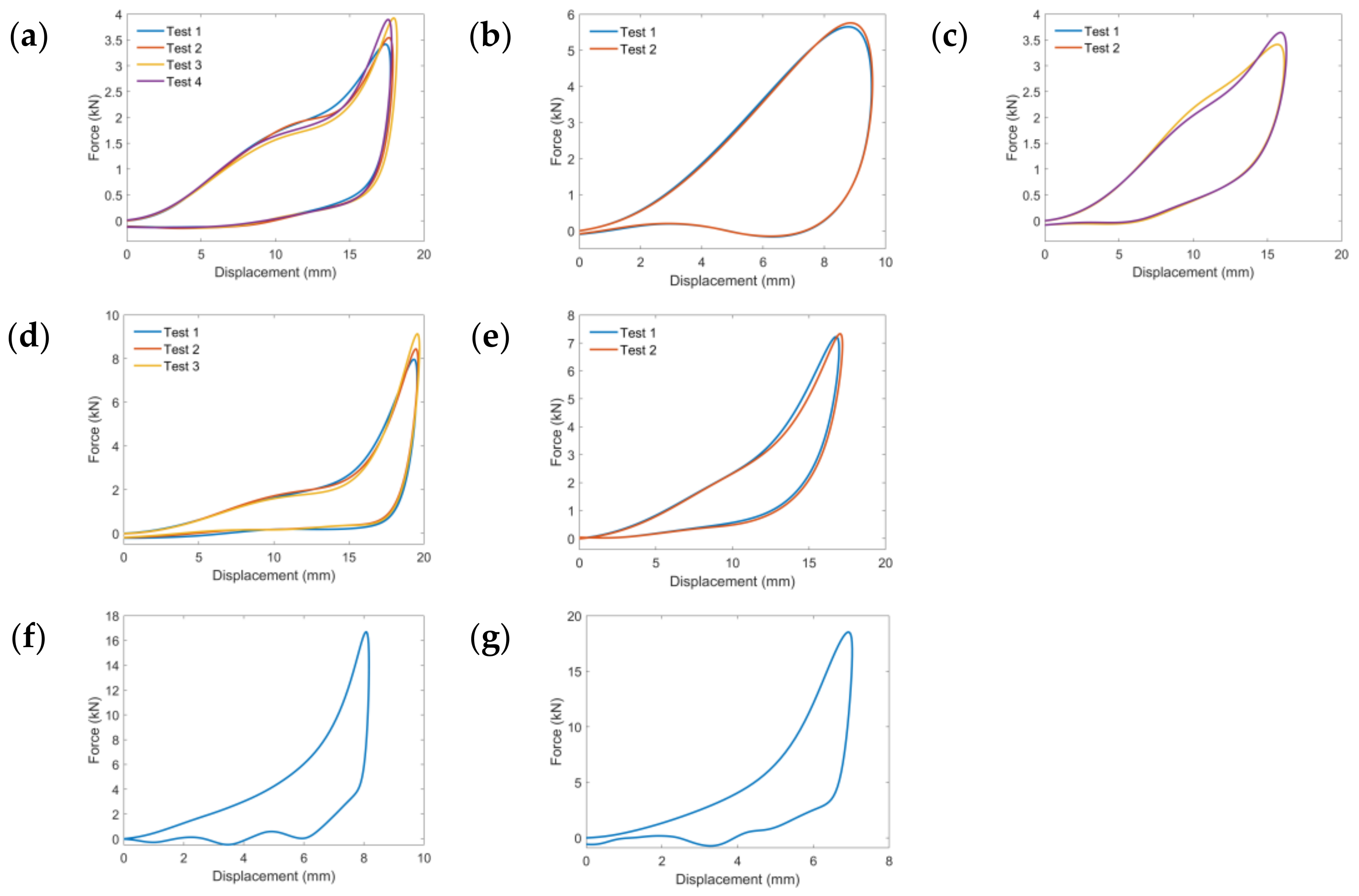
2.1. Specimen Preparation and Mechanical Tests

Four types of EAFs (shown in Figure 1) and one concrete ground with a regular plastic carpet were selected in this study to give a diversity of floor conditions. Igelkott Floor (23 mm thick, Igelkott golv AB, Stockholm, Sweden) is a synthetic rubber floor comprised of a continuous surface layer supported underneath by an array of thin rubber spikes; Kradal (13 mm thick, Classic Coachworks Pty Ltd., Mortdale, NSW, Australia) [9] is a closed celled foam based floor with a hard exterior surface of polyurethane elastomers; and SmartCells (25 mm thick, SATech, Chehalis, WA, USA) [11] is a synthetic rubber floor comprised of a continuous surface layer supported by an array of cylindrical rubber columns. Omnisports (8.5 mm thick, Tarkett Sites, Calhoun, GA, USA) [14] is a synthetic vulcanized rubber underlayment floor with a virgin rubber wear layer on top. A regular 2 mm plastic carpet on a rigid, concrete ground is set as a reference.
All the specimens were cut from related flooring products. Since the Igelkott Floor/SmartCells are multi-layer structures supported underneath by an array of rubber spikes/columns, corresponding flat dog-bone shape specimens of the rubber surface layer were implemented in tension tests with an initial cross-sectional area of 16.80 mm2/25.37 mm2 and a length of 21.50 mm/20.50 mm in the gauge section, respectively. The length-to-width ratio of the samples satisfies the requirement of a tensile testing standard for rubber-like materials [32]. Since the Kradal and OmniSports are made of polymeric foams, cylindrical specimens were investigated under compression tests and prepared with a dimension of 11.60 mm/8.45 mm in thickness and a diameter of 19.30 mm/11.85 mm, respectively (Figure 2). All the compression and tension tests were conducted at room temperature using the Instron Universal Testing Machine Model 5567. The compression or tension tests for each EAF were replicated at least three times to obtain an average value.

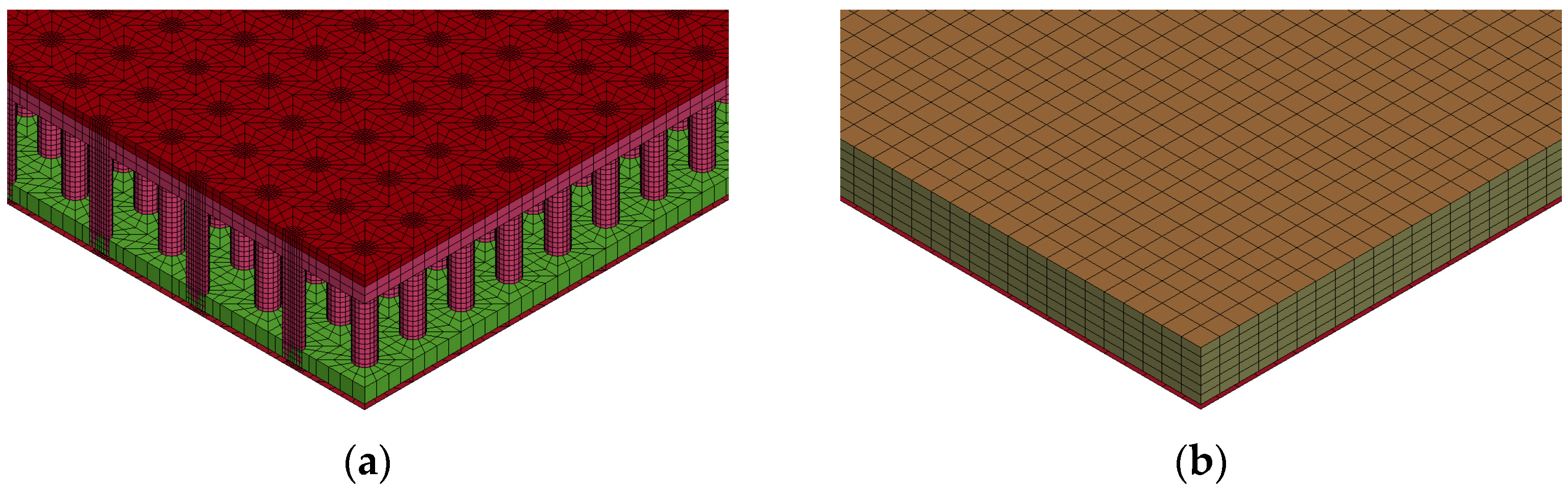
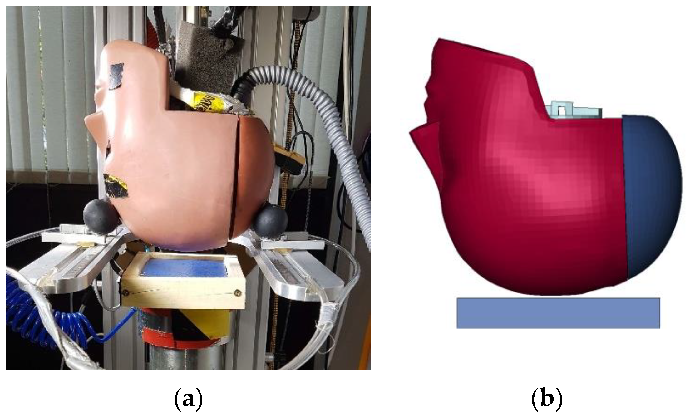
2.2. Finite Element Models of Head and Energy-Absorbing Floors

The KTH head model developed by Kleiven [24], which was validated against various impact simulations and several cadaveric experiments, was used in this study. Detailed information regarding the geometry discretization and material choice for each head component is available in previous studies [33,34]. The head model was subjected to simulation by incorporating the initial linear and angular velocities obtained from a real-world accident reconstruction, thereby simulating the ensuing impact process.
A simplification is implemented considering the contact and deformation region of head-ground collision. The FE models of four EAFs are exhibited in Figure 3. Each type of EAF was modeled as 140 mm × 140 mm and was placed inside a wooden frame with a cross-section of 15 mm wide and 25 mm thick and then mounted on the horizontal surface of the drop-testing apparatus (shown in Figure 4a). The frame is firmly fastened with screws, allowing the vertical movement of the floor samples while constraining their lateral movement. It is assumed that the rubber and foam are isotropic and have homogeneous strain properties. The constitutive behavior of the specimens was modeled using a simplified rubber/foam material model in LS-Dyna, where the stress–strain curves are implemented in the material card.
An automatic surface to surface contact incorporated a friction coefficient of 0.45 was applied between the head and each EAF in all impact cases [16]. Moreover, an interior contact was defined to prevent the material elements’ self-penetration and inversion under high impact. A single surface contact was used in LS-DYNA to account for the force transition within the floor material, which is especially important when foam bottoms out and buckling rubber has self-contact.
To validate the simulation models of each EAF, drop tests were conducted in accordance with the current test standards ASTM F1292-22 [35]. These tests involved the utilization of the HIII 50th percentile headform (4.54 kg) or a hemispheric impactor (6.5 kg with a diameter of 160 mm). The HIII head was outfitted with nine accelerometers (Endevco Corp., San Juan Capistrano, CA, USA) in a 3–2–2–2 configuration [36]. This arrangement allows for the resolution of three-dimensional (3D) angular accelerations using linear accelerometers and correction for centripetal accelerations [37]. The direction of the impact recorded by the HIII was determined by converting the 3D peak linear acceleration vector into a spherical coordinate space [38]. The HIII head was dropped from two heights: 0.6 m and 1.0 m, respectively. Only the 0.6-meter-high hemispheric drop test was carried out for the thinnest EAFs, OmniSports and Kradal. The drop simulations with identical initial conditions are illustrated in Figure 4b. Each setup was measured at least twice under the same conditions to obtain accurate results and demonstrate repeatability.

2.3. Data Analysis and Accident Reconstruction Case

The validation of the material model for four types of EAFs was assessed using CORA (CORrelation and Analysis) plus v 4.0.5 software from PDB—Partnership for Dummy Technology and Biomechanics. This rating represents an objective method to evaluate the overall time-history curves between simulation and experiment [39,40,41], using the phase shift, size, and shape ratings [42,43,44]. Detailed introduction and instructions can be found through its official website.
In this study, both global and local head injury criteria were evaluated. The head kinematics, extracted from the accelerometer positioned at the head center of gravity (CG), were analyzed in terms of the resultant linear velocity/acceleration and the resultant angular velocity/acceleration. Following the recommendations in the ASTM standard [35], all the kinematics–time curves were filtered by a second-order Butterworth filter with a cutoff frequency of 300 Hz.
In addition, the head injury criterion (HIC) was also derived. The HIC value was calculated [45] (see Equation (1)) based on the filtered resultant linear acceleration obtained from the simulated head impacts.
HIC = max t 2 t 1 1 t 2 t 1 t 1 t 2 a t d t 2.5
where a is the resultant acceleration profile, t1 and t2 define the time interval that maximizes the HIC score; usually, t2t1 is considered as 15 ms. Angular kinematics has been proven to be highly related and associated with injuries such as concussions [34]. HIC does not take rotational motion or quantities into account; thus, angular kinematics and local tissue injury criteria such as stress and strain were also included in this study.
The von Mises stress (VMS) of the skull bone and the 1st principal Green–Lagrange strain (MPS) of the brain tissue were obtained using the LS-PrePost (version 4.7.23 64-bit, 29 September 2021). The MPS was defined as the 95th percentile of the highest principal strain across all elements in the brain tissue to eliminate numerical instabilities for the entire brain from being disproportionately influenced by the response of a singular element [46,47,48]. The skull bone was originally modeled with an elastoplastic material model, where plasticity levels were set to 80 MPa for the cortical bone and 32.7 MPa for the trabecular bone [49]. The risk of skull fracture corresponding to linear acceleration and the risk of brain concussion related to the principal Green–Lagrange strain were evaluated using the risk functions presented by Chan et al. [50] and Fahlstedt et al. [51], respectively.
A pedestrian fall accident scenario described in [52] was evaluated in this study (Case 3, front impact). In this case, an elderly man fell directly forward and hit the forehead off the ground without touching any other body part or having obstructions during the fall. The corresponding head injury record is “Left sided chronic subdural hematoma. Right sided acute subdural hematoma. Midline shift to left”. During the accident reconstruction conducted using MADYMO, Gilchrist and Doorly [52] imposed an initial velocity and posture to a multi-body model representing a standing posture human, simulated the fall process, and thereby obtained the head kinematics just before the ground impact. The linear and angular velocities of the head before impact were then input into the head FE model in LS-DYNA as the initial conditions. The converted initial resultant linear velocity is 5.35 m/s (vxyz = 1.6, 0, −5.1), and the rotational velocity is 1.36 rad/s, both applied to the center of gravity of the head in head-only simulations. All simulations were performed using an explicit dynamic solving method on a multi-core Linux cluster (8.1.1 Xeon 64, 4 CPUs, LS-Dyna revision 13.0.0, double precision).

3. Results

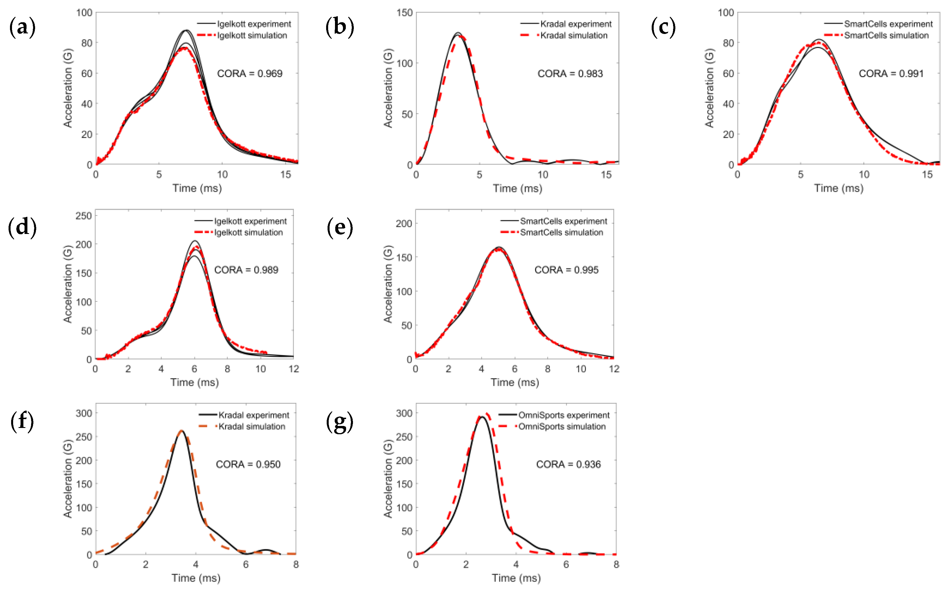
3.1. Validation of Energy-Absorbing Floors Model Using Drop Tests

According to the results of compression or tension tests performed on EAF specimens, the average loading–displacement curves from multiple tests were obtained. The strain rate dependency for the Igelkott floor and Kradal is taken into account with a table of stress–strain curves. The stress–strain curves and force–displacement curves of EAFs are illustrated in Appendix A. The main parameters in the material model are presented in Table 1. The hysteretic unloading factor and unloading shape factor were obtained by measuring the shape and area of the unloading phase in the force–displacement curves extracted from the drop tests [53,54].
The validation of the constitutive material model for each EAF was performed by comparing the results obtained from the drop tests. Figure 5 provides a visual comparison of the acceleration–time curves derived from both the experimental and simulation data. The black line corresponds to the experimental results, while the red dot line represents the simulation outcomes. Accordingly, Kradal and OmniSports exhibited a slight overestimation, whereas Igelkott Floor and SmartCells demonstrated a slight underestimation in terms of the simulation results.
The material models for four EAFs strongly correlated with the experimental results, with a total CORA rating of ≥0.9. The average values of phase shift, size, shape, and overall rating for various FE models are reported in Table 2. A high overall CORA rating indicates that the material model of each EAF is highly correlated with the experimental data and has a good agreement with the observed behavior. Meanwhile, the maximum deviation of peak acceleration is less than 3.5%. It suggests that FE models can be used to predict the behavior of each EAF accurately in subsequent simulations.

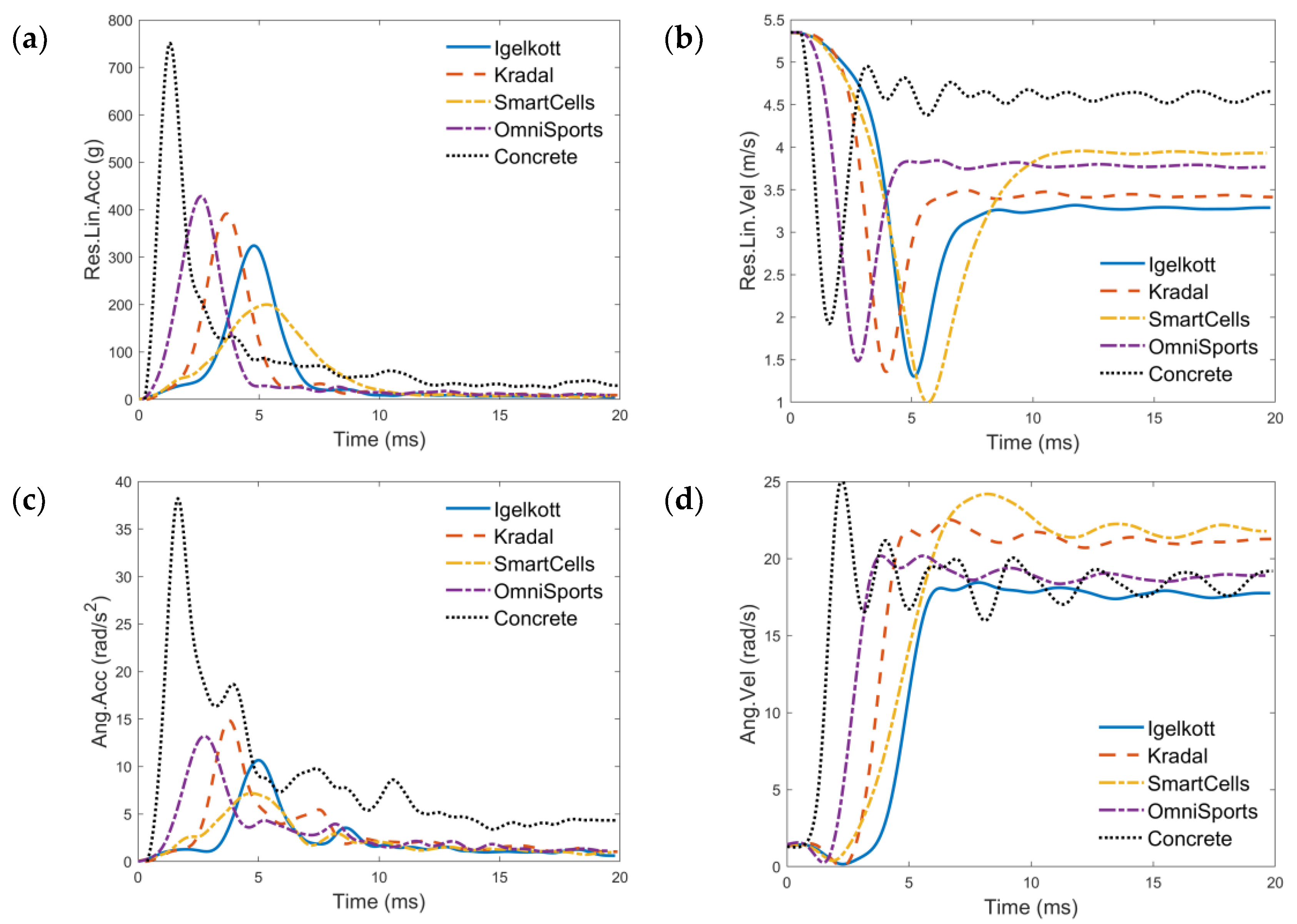
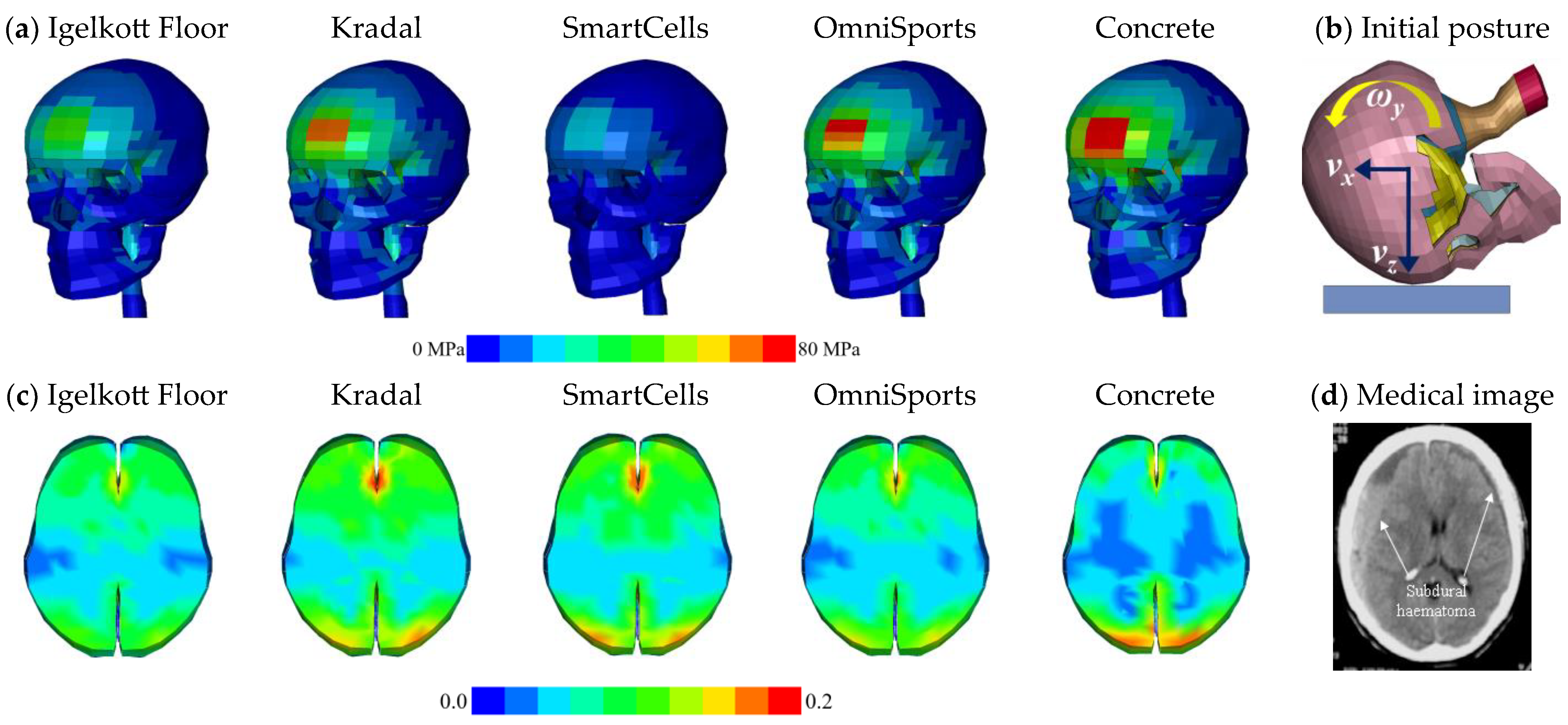
3.2. Comparison of Head Kinematics and Injuries

Subsequently, the validated FE models were utilized to assess the protective properties of the four EAFs in a representative pedestrian fall accident scenario. The head kinematics–time curves, encompassing resultant linear acceleration/velocity and resultant angular acceleration/velocity, are presented in Figure 6. Generally, the concrete ground with the regular plastic carpet produced the highest peak linear acceleration (G-max), while the SmartCells produced the lowest. The same trend was observed for the peak angular acceleration (PAA). SmartCells with the highest reduction in G-max and PAA results in the highest peak angular velocity (PAV), while the Igelkott Floor has the smallest PAV with the second largest reduction in G-max and PAA. The two thinnest EAFs, Kradal and OmniSports, produced similar kinematics, but the time for peak value had a small deviation of around 2 ms.
Figure 7 illustrates a comparison between the von Mises stress (VMS) of the cortical skull (Figure 7a), the 1st principal strain of the brain tissue (Figure 7c), and the CT scan of the fall accident case (Figure 7d). The most critical situation was observed in terms of VMS on the skull and MPS in the brain tissue when the head impacted against the concrete, as depicted by the extensive red areas. Regarding the VMS on the cortical skull, the SmartCells presented the lightest and smallest areas of stress, followed by the Igelkott floor. Meanwhile, for the MPS in brain tissue, the Igelkott showed minimal area, followed by OmniSports. Upon comparing the patient’s CT medical images, it can be observed that the high MPS region of the brain tissue corresponds to the subdural hematoma region—Figure 7d marked with arrows.
The HIC and risk of head injuries were calculated and presented in Table 3. In this particular reconstruction case, the EAFs effectively reduced the VMS in the skull by varying degrees (41%, 12%, 66%, and 10%), but such a high-velocity head impact results in HIC value all above the threshold of 1000. SmartCells shows the lowest HIC value and VMS and the lowest risk of skull fracture, followed by Igelkott Floor, while OmniSports had the highest among all EAFs for these three indicators. Igelkott Floor demonstrates the largest reduction in PAV, MPS, and the risk of concussion, followed by OmniSports. Specifically, all EAFs have more than a 90% probability of skull fracture injury except SmartCells and have more than a 65% probability of concussion except Igelkott Floor.

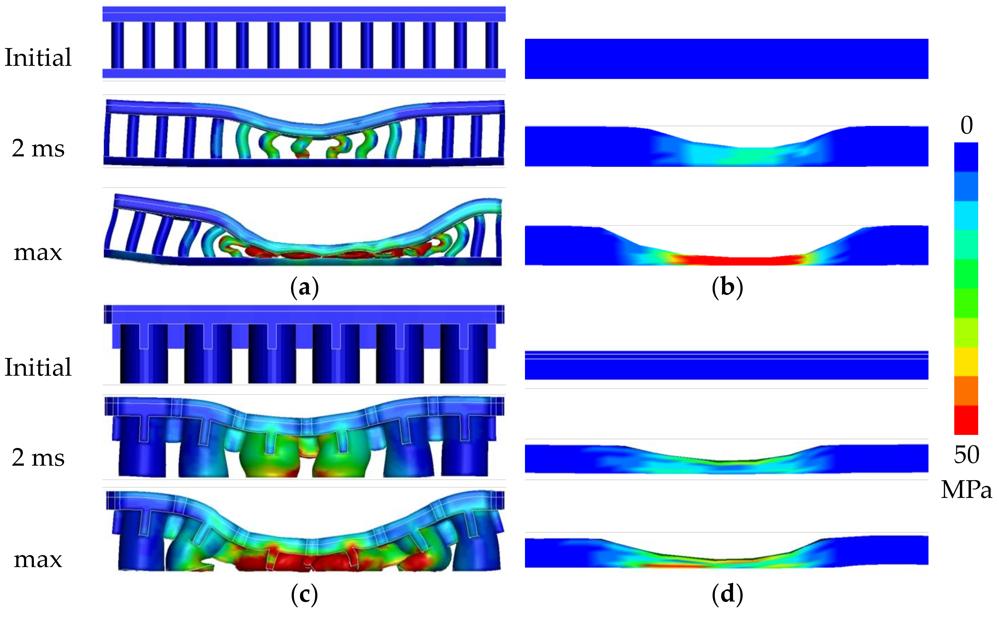
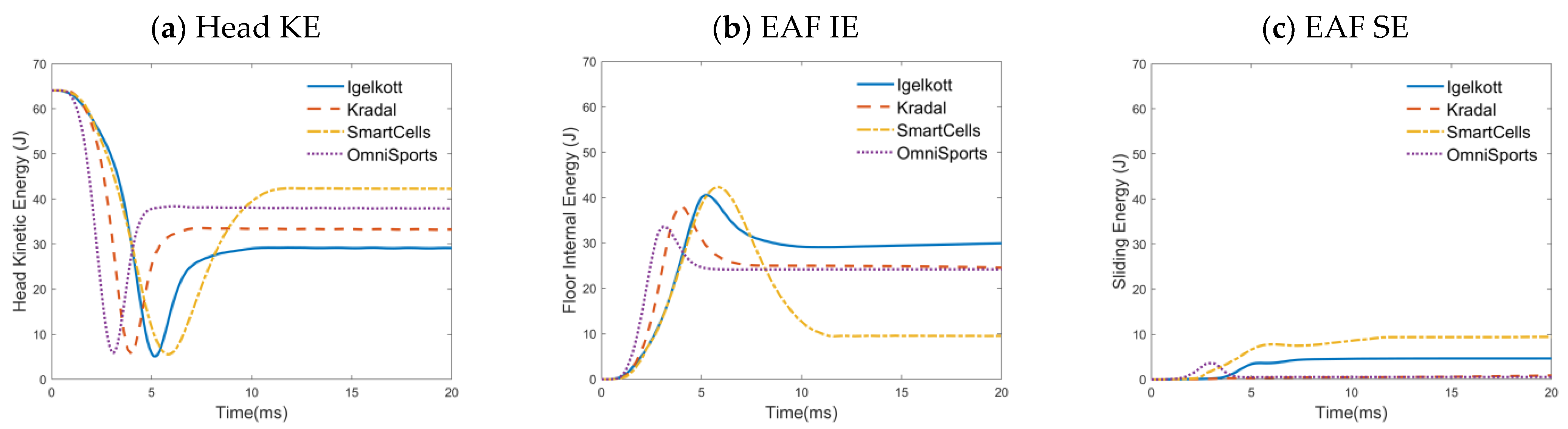
3.3. Comparison of Energy Absorption and Floor Deformation

Figure 8 presents a comparison of the deformation characteristics of the EAFs obtained from the head impact simulations. Each EAF model is illustrated in three different states: the initial, at 2 ms, and at the maximum deformation, respectively. Regarding the Igelkott Floor (Figure 8a), the deformation mechanism of the floor under the head impact area can be characterized as a typical buckling with a fixed-fixed end condition since the spikes at the ends are securely connected to the upper and lower layers. The presence of an array of thin spikes prevents the bottoming-out phenomenon. Conversely, in Kradal (Figure 8b), a distinct bottoming-out phenomenon can be observed. When terminated to large compressive strains, the foam cells inside the floor collapse, causing the opposing cell walls to crush together [55], resulting in contact between the top and bottom hard exterior surfaces. In the case of SmartCells (Figure 8c), the thick hollow rubber cylinder undergoes lateral collapse without experiencing bottoming out. This can be attributed to the presence of connecting rubber on the top half, positioned between each column. The connecting rubber not only restricts the deformation but also causes the buckling to primarily occur in the bottom half of the column. Additionally, the thinnest OmniSports (Figure 8d) does not show a significant bottoming-out phenomenon, which can be attributed to its higher Young’s modulus at low strains compared to the Kradal.
Figure 9 illustrates a visual representation of energy distribution in the accident reconstruction simulations, including the head kinetic energy, EAF internal energy, and EAF sliding energy. Head kinetic energy exhibits a similar trend to their corresponding linear velocities generally, and is attenuated to an approximate minimum value against different EAFs during impact. EAF internal energy indicates that SmartCells exhibits the highest peak energy absorption, resulting in a minimal G-max during head impact. It is followed by Igelkott Floor, while Kradal and OmniSports have the lowest peak value. However, Igelkott Floor demonstrates the greatest energy absorption after impact, while SmartCells exhibits the smallest. By considering the head’s kinematics, it is revealed that less energy from the Igelkott Floor is ultimately transferred to the head in this impact scenario, as evidenced by the lowest linear and angular velocities of the head after impact (as shown in Figure 6). Additionally, a portion of the head kinetic energy is absorbed as a term of sliding energy by SmartCells and Igelkott Floor, which is contributed by the internal contact of buckling rubber structures. The sliding energy of Kradal and OmniSports, which lack this mechanism, is negligible.

4. Discussion

This study offers valuable insights into the performance of EAFs under head impact, providing new avenues for reducing the risk of fall-related head injuries in high-fall-risk environments. While previous literature has discussed that compliant materials indeed decrease the risk of head injury, this study highlights that more can be done in terms of risk prevention with the different energy-absorbing mechanisms and capabilities. The FE models of four commercially available EAF products were established based on mechanical tests and subsequently validated using HIII/hemispheric drop tests, demonstrating a high level of consistency with a total CORA rating exceeding 0.93. These validated FE models were then employed in a series of simulations to assess the protective effectiveness of the EAFs in mitigating fall-related head injuries.
Specifically, in the accident reconstruction scenario, the use of Igelkott Floor, Kradal, SmartCells and OmniSports resulted in a 77%, 67%, 87%, 58% reduction in the HIC, a 28%, 8%, 4%, 20% reduction in the PAV of the head center of gravity, a 41%, 12%, 66%, 10% reduction in the VMS of the skull, and a 32%, 15%, 11%, 17% reduction in MPS within the brain tissue, respectively. Among the EAFs, SmartCells provided the largest reduction in G-max and resulted in the lowest skull fracture risk, around 45.6%. On the other hand, Igelkott Floor provided the largest reduction in PAV and resulted in the lowest concussion risk of around 37.5%. Kradal and OmniSports exhibited similar behavior in terms of head kinematics and energy absorption.
We did not find a strong association between brain strain reduction and contact force decrease. It has previously been found that large contact forces cause high stresses in the skull with an associated higher risk of skull fractures, while the human brain is more sensitive to large strains due to rotational loading [47]. The brain injury risk was calculated based on previously developed risk curves based on concussions in sports [50,51]. SmartCells has the highest attenuation in G-max under high-velocity impact and a similar capability for MPS reduction as Kradal. Igelkott Floor ranks second in terms of G-max attenuation and shows the largest reduction in MPS. These observations are primarily influenced by the energy-absorbing mechanisms of different structures and materials. Generally, floors with greater thickness and lower surface stiffness tend to undergo greater deformation upon impact, leading to increased contact area and contact time. Meanwhile, the different end constraints of the columns (fixed-fixed for thin spikes and fixed-sliding for hollow cylinders) also contribute to the buckling deformation [56]. For a column or spike, which can be considered as a single energy-absorbing unit inside the SmartCells and the Igelkott Floor, its axial stress during buckling depends on the cross-sectional area and effective length. The latter structural unit, due to being composed of a multitude of slender spikes, has more buckling in various directions and thus influences the head rotational kinematics in angular impact, which is associated with less brain tissue strain and better reduction of concussion risk.
This study focuses on head injuries, but other injuries, such as hip fractures, are equally common in fall incidents. Laing and Robinovitch [11] used a hip impact simulator to assess femoral neck force for four energy-absorbing floors and reported that two commercially available compliant floors (SmartCell, SofTile) can attenuate femoral impact force by up to 50% while having only a limited influence on balance in older women. Bhan et al. [9] indicated that safety floors demonstrated significantly increased energy absorption (20.7% to 28.3%) compared to a baseline resilient-rolled-sheeting system. Michal et al. [57] used a materials testing system to characterize the ability of floors to absorb energy during simulated head and hip impacts. The results suggest that the safety floors effectively absorb substantial impact energy without increasing footfall deflections. Numerous reports [13,58,59] compared the reduction in head linear kinematics, including peak force and HIC, and determined the protective performance. The results in terms of reduction in angular kinematics and brain strain in this study further illustrate the potential for brain injury risk reduction of EAFs.
There are some limitations associated with the current study. Firstly, the FE simulations are implemented without the inclusion of the neck and the rest of the body, which could influence the impact dynamics and kinematics of the head [60,61,62,63,64,65]. Fahlstedt et al. [16] compared the difference in linear and angular head kinematics between a head-only model and a full-body model during the impact against playground surfaces with various stiffness. The results indicated that the head-only model presented slightly higher values compared to the full-body model [49] in linear kinematics, while the angular kinematics were underestimated by the simplification of excluding the body. It indicated that the current method is conservative if we assume the full-body model more accurately captures the actual scenario. More research is needed to understand the influence better. Secondly, the lack of data from real-world fall accidents involving brain trauma is also one of the limitations. Given that only one typical head impact case was selected, fall accidents in the real world can vary greatly. Validation of the head kinematics in several reconstructed cases and statistical analysis of the initial conditions at the impact moment is beyond the scope of the current study but could be considered in future research. Additionally, the drop validation was conducted with a unidirectional impact, while the falls can have a vector of motion that induces shear in the floor material. The oblique loading and mechanical properties in the shear/anisotropic deserve further study. There are also other floor products or variations with different mechanical properties and energy absorption efficiencies that were not specifically examined in this study. Further research could explore these additional options to provide a more comprehensive understanding of the potential range of flooring solutions.

Author Contributions

Conceptualization, S.K.; methodology, Q.H.; software, Q.H.; validation, Q.H.; formal analysis, Q.H.; investigation, S.K. and Q.H.; resources, S.K. and Q.H.; data curation, Q.H.; writing—original draft preparation, Q.H.; writing—review and editing, S.K.; visualization, Q.H.; supervision, S.K.; project administration, S.K.; funding acquisition, S.K. All authors have read and agreed to the published version of the manuscript.

Funding

This research was funded by a grant from Sweden’s innovation agency, Vinnova (D.nr.: 2013-04465, 2021-01598).

Institutional Review Board Statement

Not applicable.

Informed Consent Statement

Not applicable.

Data Availability Statement

Data is contained within the article.

Acknowledgments

The computations were enabled by resources provided by the Swedish National Infrastructure for Computing (SNIC), at the PDC Center for High Performance Computing, KTH Royal Institute of Technology, partially funded by the Swedish Research Council through grant agreement no. 2018-05973.

Conflicts of Interest

S.K. has a financial interest in a company aiming to produce safety flooring (Igelkott Golv AB), and both he and the company may benefit from the results of this research. The remaining author declares that the research was conducted in the absence of any commercial or financial relationships that could be construed as a potential conflict of interest.

Appendix A

The mechanical behavior of Igelkott floor and Kradal under dynamic tension or compression were considered using rate dependency curves, whereas constant stress–strain were used on SmartCells and OmniSports. In this case, the acceleration–time curves in the simulation and experimental results have a good agreement and a high CORA score. The strain rates in dynamic mechanical tests are 0.01 s−1, 0.1 s−1, 1.0 s−1, and 10 s−1, respectively. An empirical formula [66], based on the Gibson model [67], and a constitutive equation [68] are implemented to extrapolate and describe the rate-dependent stress–strain curves of the samples. The stress–strain curves of four EAFs used in LS-DYNA were illustrated in Figure A1. The experimental stress–strain curves of four EAFs in mechanical tests are illustrated in Figure A2. The force–displacement curves of four EAFs drop tests are illustrated in Figure A3.
Figure A1. The stress–strain curves of four EAF specimens used in LS-DYNA, (a) tension tests of Igelkott Floor, (b) compression tests of Kradal, (c) tension tests of SmartCells, (d) compression tests of OmniSports, respectively.
Applsci 13 13260 g0a1
Figure A2. The experimental stress–strain curves of four EAF specimens from mechanical tests under the same strain rate, (a) tension tests of Igelkott Floor, (b) compression tests of Kradal, (c) tension tests of SmartCells, (d) compression tests of OmniSports, respectively.
Applsci 13 13260 g0a2aApplsci 13 13260 g0a2b
Figure A3. The force–displacement curves for HIII drop tests and hemispheric drop tests, (a) Igelkott Floor HIII 60 cm; (b) Kradal HIII 60 cm; (c) SmartCells HIII 60 cm; (d) Igelkott Floor HIII 100 cm; (e) SmartCells HIII 100 cm; (f) Kradal hemispheric 60 cm; (g) OmniSports hemispheric 60 cm.
Applsci 13 13260 g0a3

References

  1. Pfortmueller, C.A.; Kunz, M.; Lindner, G.; Zisakis, A.; Puig, S.; Exadaktylos, A.K. Fall-related emergency department admission: Fall environment and settings and related injury patterns in 6357 patients with special emphasis on the elderly. Sci. World J. 2014, 2014, 256519. [Google Scholar] [CrossRef]
  2. Mackey, D.C.; Lachance, C.C.; Wang, P.T.; Feldman, F.; Laing, A.C.; Leung, P.M.; Hu, X.J.; Robinovitch, S.N. The Flooring for Injury Prevention (Flip) Study of compliant flooring for the prevention of fall-related injuries in long-term care: A randomized trial. PLoS Med. 2019, 16, e1002843. [Google Scholar] [CrossRef] [PubMed]
  3. Kannus, P.; Parkkari, J.; Koskinen, S.; Niemi, S.; Palvanen, M.; Järvinen, M.; Vuori, I. Fall-induced injuries and deaths among older adults. Jama 1999, 281, 1895–1899. [Google Scholar] [CrossRef] [PubMed]
  4. Osoba, M.Y.; Rao, A.K.; Agrawal, S.K.; Lalwani, A.K. Balance and gait in the elderly: A contemporary review. Laryngoscope Investig. Otolaryngol. 2019, 4, 143–153. [Google Scholar] [CrossRef] [PubMed]
  5. Cheng, T.A.; Bell, J.M.; Haileyesus, T.; Gilchrist, J.; Sugerman, D.E.; Coronado, V.G. Nonfatal playground-related traumatic brain injuries among children, 2001–2013. Pediatrics 2016, 137, e20152721. [Google Scholar] [CrossRef]
  6. Beedham, W.; Peck, G.; Richardson, S.E.; Tsang, K.; Fertleman, M.; Shipway, D.J. Head injury in the elderly–an overview for the physician. Clin. Med. 2019, 19, 177. [Google Scholar] [CrossRef]
  7. Kannus, P.; Niemi, S.; Parkkari, J.; Mattila, V.; Sievänen, H. Fall-induced hospital-treated traumatic brain injuries among elderly Finns in 1970–2017. Arch. Gerontol. Geriatr. 2020, 86, 103958. [Google Scholar] [CrossRef] [PubMed]
  8. Adekoya, N.; Thurman, D.J.; Webb, K.W.; White, D.D. Surveillance for traumatic brain injury deaths—United States, 1989–1998. MMWR Surveill. Summ. 2002, 51, 1–14. [Google Scholar]
  9. Lachance, C.C.; Jurkowski, M.P.; Dymarz, A.C.; Robinovitch, S.N.; Feldman, F.; Laing, A.C.; Mackey, D.C. Compliant flooring to prevent fall-related injuries in older adults: A scoping review of biomechanical efficacy, clinical effectiveness, cost-effectiveness, and workplace safety. PLoS ONE 2017, 12, e0171652. [Google Scholar] [CrossRef]
  10. Laing, A.C.; Tootoonchi, I.; Hulme, P.A.; Robinovitch, S.N. Effect of compliant flooring on impact force during falls on the hip. J. Orthop. Res. 2006, 24, 1405–1411. [Google Scholar] [CrossRef]
  11. Laing, A.C.; Robinovitch, S.N. Low stiffness floors can attenuate fall-related femoral impact forces by up to 50% without substantially impairing balance in older women. Accid. Anal. Prev. 2009, 41, 642–650. [Google Scholar] [CrossRef]
  12. Wright, A.D.; Laing, A.C. The influence of novel compliant floors on balance control in elderly women—A biomechanical study. Accid. Anal. Prev. 2011, 43, 1480–1487. [Google Scholar] [CrossRef] [PubMed]
  13. Wright, A.D.; Laing, A.C. The influence of headform orientation and flooring systems on impact dynamics during simulated fall-related head impacts. Med. Eng. Phys. 2012, 34, 1071–1078. [Google Scholar] [CrossRef] [PubMed]
  14. Hanger, H.C. Low-impact flooring: Does it reduce fall-related injuries? J. Am. Med. Dir. Assoc. 2017, 18, 588–591. [Google Scholar] [CrossRef] [PubMed]
  15. Yu, C.; Wang, F.; Wang, B.; Li, G.; Li, F. A computational biomechanics human body model coupling finite element and multibody segments for assessment of head/brain injuries in car-to-pedestrian collisions. Int. J. Environ. Res. Public Health 2020, 17, 492. [Google Scholar] [CrossRef] [PubMed]
  16. Fahlstedt, M.; Kleiven, S.; Li, X. Current playground surface test standards underestimate brain injury risk for children. J. Biomech. 2019, 89, 1–10. [Google Scholar] [CrossRef] [PubMed]
  17. Wu, T.; Alshareef, A.; Giudice, J.S.; Panzer, M.B. Explicit Modeling of White Matter Axonal Fiber Tracts in a Finite Element Brain Model. Ann. Biomed. Eng. 2019, 47, 1908–1922. [Google Scholar] [CrossRef] [PubMed]
  18. Miller, L.E.; Urban, J.E.; Stitzel, J.D. Development and Validation of an Atlas-Based Finite Element Brain Model. Biomech. Model. Mechanobiol. 2016, 15, 1201–1214. [Google Scholar] [CrossRef]
  19. Sahoo, D.; Deck, C.; Willinger, R. Development and Validation of an Advanced Anisotropic Visco-Hyperelastic Human Brain Fe Model. J. Mech. Behav. Biomed. Mater. 2014, 33, 24–42. [Google Scholar] [CrossRef]
  20. Miller, K. Constitutive Model of Brain Tissue Suitable for Finite Element Analysis of Surgical Procedures. J. Biomech. 1999, 32, 531–537. [Google Scholar] [CrossRef]
  21. Giudice, J.S.; Zeng, W.; Wu, T.; Alshareef, A.; Shedd, D.F.; Panzer, M.B. An analytical review of the numerical methods used for finite element modeling of traumatic brain injury. Ann. Biomed. Eng. 2019, 47, 1855–1872. [Google Scholar] [CrossRef] [PubMed]
  22. Mao, H.; Zhang, L.; Jiang, B.; Genthikatti, V.V.; Jin, X.; Zhu, F.; Makwana, R.; Gill, A.; Jandir, G.; Singh, A. Development of a finite element human head model partially validated with thirty five experimental cases. J. Biomech. Eng. 2013, 135, 111002. [Google Scholar] [CrossRef] [PubMed]
  23. Ghajari, M.; Hellyer, P.J.; Sharp, D.J. Computational modelling of traumatic brain injury predicts the location of chronic traumatic encephalopathy pathology. Brain 2017, 140, 333–343. [Google Scholar] [CrossRef] [PubMed]
  24. Kleiven, S. Predictors for Traumatic Brain Injuries Evaluated through Accident Reconstructions. In Proceedings of the 51st Stapp Car Crash Conference, San Diego, CA, USA, 29–31 October 2007. [Google Scholar]
  25. Li, X.; Kleiven, S. Improved safety standards are needed to better protect younger children at playgrounds. Sci. Rep. 2018, 8, 15061. [Google Scholar] [CrossRef]
  26. Atsumi, N.; Nakahira, Y.; Iwamoto, M. Development and validation of a head/brain FE model and investigation of influential factor on the brain response during head impact. Int. J. Veh. Saf. 2016, 9, 1–23. [Google Scholar] [CrossRef]
  27. Baeck, K.; Vander Sloten, J.; Goffin, J. Biomechanical Modeling of Head Impacts: A Critical Analysis of Finite Element Modeling Approaches (Biomechanische Modellering van Hoofdimpacten: Een Kritische Analyse van Eindige Elementen Modelleringsmethoden). Ph.D. Thesis, Katholieke Universiteit Leuven, Leuven, Belgium, 2013. [Google Scholar]
  28. Duncan, O.; Shepherd, T.; Moroney, C.; Foster, L.; Venkatraman, P.D.; Winwood, K.; Allen, T.; Alderson, A. Review of auxetic materials for sports applications: Expanding options in comfort and protection. Appl. Sci. 2018, 8, 941. [Google Scholar] [CrossRef]
  29. Horgan, T.J.; Gilchrist, M.D. Influence of FE model variability in predicting brain motion and intracranial pressure changes in head impact simulations. Int. J. Crashworthiness 2004, 9, 401–418. [Google Scholar] [CrossRef]
  30. Zhou, Z.; Li, X.; Kleiven, S. Fluid–structure interaction simulation of the brain–skull interface for acute subdural haematoma prediction. Biomech. Model. Mechanobiol. 2019, 18, 155–173. [Google Scholar] [CrossRef] [PubMed]
  31. Zhao, W.; Ji, S. Brain strain uncertainty due to shape variation in and simplification of head angular velocity profiles. Biomech. Model. Mechanobiol. 2017, 16, 449–461. [Google Scholar] [CrossRef]
  32. ISO 37:2017; Rubber, Vulcanized or Thermoplastic—Determination of Tensile Stress-Strain Properties. International Organization for Standardization: Geneva, Switzerland, 2017.
  33. Kleiven, S. Evaluation of head injury criteria using a finite element model validated against experiments on localized brain motion, intracerebral acceleration, and intracranial pressure. Int. J. Crashworthiness 2006, 11, 65–79. [Google Scholar] [CrossRef]
  34. Kleiven, S. Influence of direction and duration of impacts to the human head evaluated using the finite element method. In Proceedings of the IRCOBI Conference, Prague, Czech Republic, 21–23 September 2005. [Google Scholar]
  35. ASTM F1292-22; Standard Specification for Impact Attenuation of Surfacing Materials within the Use Zone of Playground Equipment. ASTM International: West Conshohocken, PA, USA, 2022.
  36. Beckwith, J.G.; Greenwald, R.M.; Chu, J.J. Measuring head kinematics in football: Correlation between the head impact telemetry system and Hybrid III headform. Ann. Biomed. Eng. 2012, 40, 237–248. [Google Scholar] [CrossRef] [PubMed]
  37. Padgaonkar, A.J.; Krieger, K.; King, A. Measurement of angular acceleration of a rigid body using linear accelerometers. J. Appl. Mech. Sep. 1975, 42, 552–556. [Google Scholar] [CrossRef]
  38. Lindgren, N.; Halldin, P.; Fahlstedt, M. Influence of Headform on Assessments and Ratings of the Protective Performance of Bicycle Helmets. In Proceedings of the IRCOBI Conference, Porto, Portugal, 14–16 September 2022. [Google Scholar]
  39. Gehre, C.; Gades, H.; Wernicke, P. Objective rating of signals using test and simulation responses. In Proceedings of the 21st International Technical Conference on the Enhanced Safety of Vehicles Conference (ESV), Stuttgart, Germany, 15 June 2009. [Google Scholar]
  40. Barbat, S.; Fu, Y.; Zhan, Z.; Yang, R.-J.; Gehre, C. Objective rating metric for dynamic systems. In Proceedings of the 23rd International Technical Conference on the Enhanced Safety of Vehicles (ESV), Seoul, Republic of Korea, 27–30 May 2013; p. 2. [Google Scholar]
  41. Untaroiu, C.; Shin, J.; Lu, Y.-C. Assessment of a dummy model in crash simulations using rating methods. Int. J. Automot. Technol. 2013, 14, 395–405. [Google Scholar] [CrossRef]
  42. Gierczycka, D.; Cronin, D. Investigation of Injury Metric Sensitivity to Thorax Impact Loading Using a Human Body Model. In Proceedings of the IRCOBI Conference, Berlin, Germany, 10–12 September 2014. [Google Scholar]
  43. Decker, W.; Baker, A.; Ye, X.; Brown, P.; Stitzel, J.; Gayzik, F.S. Development and multi-scale validation of a finite element football helmet model. Ann. Biomed. Eng. 2020, 48, 258–270. [Google Scholar] [CrossRef] [PubMed]
  44. Bastien, C.; Diederich, A.; Christensen, J.; Ghaleb, S. Improving correlation accuracy of crashworthiness applications by combining the CORA and MADM methods. Proc. Inst. Mech. Eng. Part D J. Automob. Eng. 2021, 236, 3192–3200. [Google Scholar] [CrossRef]
  45. Versace, J. A review of the severity index. In Proceedings of the 15th Stapp Car Crash Conference, Coronado, CA, USA, 17–19 November 1971. [Google Scholar]
  46. Panzer, M.B.; Myers, B.S.; Capehart, B.P.; Bass, C.R. Development of a finite element model for blast brain injury and the effects of CSF cavitation. Ann. Biomed. Eng. 2012, 40, 1530–1544. [Google Scholar] [CrossRef]
  47. Kleiven, S. Why most traumatic brain injuries are not caused by linear acceleration but skull fractures are. Front. Bioeng. Biotechnol. 2013, 1, 15. [Google Scholar] [CrossRef] [PubMed]
  48. Gabler, L.F.; Crandall, J.R.; Panzer, M.B. Assessment of kinematic brain injury metrics for predicting strain responses in diverse automotive impact conditions. Ann. Biomed. Eng. 2016, 44, 3705–3718. [Google Scholar] [CrossRef]
  49. Fahlstedt, M.; Halldin, P.; Kleiven, S. The protective effect of a helmet in three bicycle accidents—A finite element study. Accid. Anal. Prev. 2016, 91, 135–143. [Google Scholar] [CrossRef]
  50. Chan, P.; Lu, Z.; Rigby, P.; Takhounts, E.; Zhang, J.; Yoganandan, N.; Pintar, F. Development of generalized linear skull fracture criterion. In Proceedings of the 20th International Technical Conference on the Enhanced Safety of Vehicles Conference (ESV), Lyon, France, 18–21 June 2007. [Google Scholar]
  51. Fahlstedt, M.; Meng, S.; Kleiven, S. Influence of Strain Post-Processing on Brain Injury Prediction. J. Biomech. 2022, 132, 110940. [Google Scholar] [CrossRef] [PubMed]
  52. Gilchrist, M.D.; Doorly, M.C. An in-depth analysis of real world fall accidents involving brain trauma. In The Pathomechanics of Tissue Injury and Disease, and the Mechanophysiology of Healing; Gefen, A., Ed.; Research Signpost: Tel Aviv, Israel, 2009; Chapter 2; pp. 19–66. [Google Scholar]
  53. Ozturk, U.E.; Anlas, G. Finite element analysis of expanded polystyrene foam under multiple compressive loading and unloading. Mater. Des. 2011, 32, 773–780. [Google Scholar] [CrossRef]
  54. Li, Z.; Zhou, H.; Wang, Y.; Zhou, H.; Peng, X. Modelling energy dissipation and hysteresis of woven fabrics with large deformation under single loading-unloading cycle. Compos. Struct. 2022, 279, 114781. [Google Scholar] [CrossRef]
  55. Di Landro, L.; Sala, G.; Olivieri, D. Deformation mechanisms and energy absorption of polystyrene foams for protective helmets. Polym. Test. 2002, 21, 217–228. [Google Scholar] [CrossRef]
  56. Gent, A.N. Elastic stability of rubber compression springs. J. Mech. Eng. Sci. 1964, 6, 318–326. [Google Scholar] [CrossRef]
  57. Glinka, M.N.; Karakolis, T.; Callaghan, J.P.; Laing, A.C. Characterization of the protective capacity of flooring systems using force-deflection profiling. Med. Eng. Phys. 2013, 35, 108–115. [Google Scholar] [CrossRef]
  58. Drahota, A.; Felix, L.M.; Raftery, J.; Keenan, B.E.; Lachance, C.C.; Mackey, D.C.; Markham, C.; Laing, A.C. The SAFEST review: A mixed methods systematic review of shock-absorbing flooring for fall-related injury prevention. BMC Geriatr. 2022, 22, 1–28. [Google Scholar] [CrossRef]
  59. Lachance, C.C.; Feldman, F.; Laing, A.C.; Leung, P.M.; Robinovitch, S.N.; Mackey, D.C. Study protocol for the Flooring for Injury Prevention (FLIP) Study: A randomised controlled trial in long-term care. Inj. Prev. 2016, 22, 453–460. [Google Scholar] [CrossRef]
  60. Whyte, T.; Stuart, C.; Mallory, A.; Ghajari, M.; Plant, D.; Siegmund, G.P.; Cripton, P.A. A review of impact testing methods for headgear in sports: Considerations for improved prevention of head injury through research and standards. J. Biomech. Eng. 2019, 141, 070803. [Google Scholar] [CrossRef]
  61. Ghajari, M.; Peldschus, S.; Galvanetto, U.; Iannucci, L. Effects of the presence of the body in helmet oblique impacts. Accid. Anal. Prev. 2013, 50, 263–271. [Google Scholar] [CrossRef]
  62. Verschueren, P. Biomechanical Analysis of Head Injuries Related to Bicycle Accidents and a New Bicycle Helmet Concept (Biomechanische Analyse van Hoofdletsels Gerelateerd aan Fietsongevallen en een Nieuw Fietshelmconcept). Ph.D. Thesis, Katholieke Universiteit Leuven, Leuven, Belgium, 2009. [Google Scholar]
  63. Shewchenko, N.; Withnall, C.; Keown, M.; Gittens, R.; Dvorak, J. Heading in football. Part 2: Biomechanics of ball heading and head response. Br. J. Sports Med. 2005, 39, i26–i32. [Google Scholar] [CrossRef] [PubMed]
  64. Newman, J.A.; Beusenberg, M.C.; Shewchenko, N.; Withnall, C.; Fournier, E. Verification of biomechanical methods employed in a comprehensive study of mild traumatic brain injury and the effectiveness of American football helmets. J. Biomech. 2005, 38, 1469–1481. [Google Scholar] [CrossRef]
  65. Beusenberg, M.; Shewchenko, N.; Newman, J.; de Lange, R.; Cappon, H. Head, neck, and body coupling in reconstructions of helmeted head impacts. Int. Res. Counc. Biomech. Impact Isle Man UK 2001, 95, 295–310. [Google Scholar]
  66. Avalle, M.; Belingardi, G.; Ibba, A. Mechanical models of cellular solids: Parameters identification from experimental tests. Int. J. Impact Eng. 2007, 34, 3–27. [Google Scholar] [CrossRef]
  67. Gibson, L.J. Cellular solids. Mrs Bull. 2003, 28, 270–274. [Google Scholar] [CrossRef]
  68. Nagy, A.; Ko, W.; Lindholm, U. Mechanical behavior of foamed materials under dynamic compression. J. Cell. Plast. 1974, 10, 127–134. [Google Scholar] [CrossRef]
Figure 1. Four types of energy-absorbing flooring samples compared in this study. The image of (d) OmniSports is from its official website (https://proffs.tarkett.se/, accessed on 22 April 2023). (a) Igelkott Floor; (b) Kradal; (c) SmartCells; (d) OmniSports.
Applsci 13 13260 g001
Figure 2. Four energy-absorbing floor specimens for the compression/tension tests. (a) Igelkott Floor; (b) Kradal; (c) SmartCells; (d) OmniSports.
Applsci 13 13260 g002
Figure 3. Finite element models of four energy-absorbing flooring structures in simulations. (a) Igelkott Floor; (b) Kradal; (c) SmartCells; (d) OmniSports.
Applsci 13 13260 g003aApplsci 13 13260 g003b
Figure 4. (a) Setup of HIII drop test against different types of EAFs, (b) corresponding HIII FE simulation model.
Applsci 13 13260 g004
Figure 5. The acceleration–time curves for HIII drop tests and hemispheric drop tests, with related overall CORA score, (a) Igelkott Floor HIII 60 cm; (b) Kradal HIII 60 cm; (c) SmartCells HIII 60 cm; (d) Igelkott Floor HIII 100 cm; (e) SmartCells HIII 100 cm; (f) Kradal hemispheric 60 cm; (g) OmniSports hemispheric 60 cm.
Applsci 13 13260 g005
Figure 6. The kinematics–time curves of the head CG in fall accident reconstructions case [52] against four types of EAFs: (a) resultant linear acceleration, (b) resultant linear velocity, (c) angular acceleration, (d) angular velocity.
Applsci 13 13260 g006
Figure 7. (a) Comparison of peak von Mises stresses (MPa) on the cortical bone against four EAFs and concrete ground of Case 3. (b) Accident reconstruction of head impact initial posture on forward falling. (c) Comparison of the peak 1st principal strain on the brain tissue of Case 3. (d) the medical image of Case 3, which is from the research [52]. Copyright (CC BY-NC-ND 3.0 IE).
Applsci 13 13260 g007
Figure 8. Comparison of peak von Mises stresses (MPa) of four energy-absorbing floors in the accident reconstruction case: the former is at 2 ms and the latter is at the maximum deformation state, respectively. (a) Igelkott Floor; (b) Kradal; (c) SmartCells; (d) OmniSports.
Applsci 13 13260 g008
Figure 9. Energy in head impact simulation (a) kinetic energy of head, (b) internal energy of EAFs, and (c) sliding energy of EAFs.
Applsci 13 13260 g009
Table 1. Summary of four EAFs’ main material properties and dimensions.
Igelkott FloorKradalSmartCellsOmniSports
Poisson’s ratio0.490.010.490.3
Hysteresis unloading factor0.20.150.20.05
Unloading shape factor4.04.04.05.0
Thickness (mm)2313258.5
Table 2. Results of average CORA rating for four types of EAFs.
CorridorShapeSizePhase ShiftOverall
Igelkott Floor0.9770.9960.8831.00.979
Kradal0.9820.9800.9071.00.966
SmartCells0.9760.9850.9941.00.993
OmniSports0.9370.9640.8141.00.936
Table 3. Simulation results of the fall accident cased against different EAFs.
HICPeak Angular
Velocity [rad/s]
Peak von Mises
Stress [MPa]
Peak 1st
Principal Strain
Risk of Skull
Fracture *
Risk of
Concussion **
Igelkott240018470.1710.9470.375
Kradal349323700.2160.9840.703
SmartCell130424270.2250.4560.765
OmniSports435620720.2090.9910.652
Concrete10,50725800.2530.9990.901
* Based on the risk curve function from Chan et al. (2007) [50]. ** Based on the risk curve function from Fahlstedt et al. (2022) [49].
Disclaimer/Publisher’s Note: The statements, opinions and data contained in all publications are solely those of the individual author(s) and contributor(s) and not of MDPI and/or the editor(s). MDPI and/or the editor(s) disclaim responsibility for any injury to people or property resulting from any ideas, methods, instructions or products referred to in the content.

