Article

Enhanced Mechanical Joining between Carbon-Fiber- Reinforced Plastic and Steel Plates Using the Clearance-Filling Effect of Structural Adhesive

1
Department of Materials Science and Convergence Technology, Engineering Research Institute (ERI), Gyeongsang National University, Jinju 52828, Republic of Korea
2
Research Institute of Clean Manufacturing System, Korea Institute of Industrial Technology (KITECH), Cheonan 31056, Republic of Korea
3
School of Mechanical Engineering, Korea University of Technology and Education (KOREATECH), Cheonan 31253, Republic of Korea
*
Author to whom correspondence should be addressed.
Appl. Sci. 2023, 13(7), 4332; https://doi.org/10.3390/app13074332
Submission received: 26 February 2023 / Revised: 23 March 2023 / Accepted: 26 March 2023 / Published: 29 March 2023

Abstract

:
When carbon-fiber-reinforced plastic (CFRP) and steel are joined using blind riveting and bolting, fastener inclination occurs due to the clearance between the fastener and hole. To this end, this study investigated the unavoidable occurrence of clearance when joining metal and composite materials using mechanical fastening. The effect of inclination on the lap shear strength (LSS) was quantitatively investigated under various conditions. In riveting, breakage occurred mainly in the rivet; the LSS between the CFRP and steel improved by approximately 33% when the clearance was filled with structural adhesive compared to that in the unfilled state. In bolting, a washer was essential since it not only reduced the force exerted on the bolt but also reduced the bending deformation of the steel plate where breakage occurred. The clearance-filling effect showed the same effect as using a washer even without using it. In addition, the LSS was improved by approximately 10% by filling the clearance with a structural adhesive in the case of bolting with washers. Additionally, the force distribution for the fastening segment was calculated under the application of an external force, and the results demonstrated that hybrid-bonded fastening using a clearance-filling during mechanical bonding is essential for strong fastening.

1. Introduction

For a long time, many parts of transportation vehicles and moving structures, such as aircraft wings and wind turbine blades, have been replaced from metal to fiber-reinforced plastics for the purpose of lightweighting for energy efficiency. Fiber-reinforced plastics have a high strength-to-weight ratio, which allows for the lightweighting of products [1,2,3]. However, it is challenging to manufacture all parts using fiber-reinforced plastic alone, and sometimes it is advantageous to use them together with metal to utilize metal properties such as electrical conductivity and thermal conductivity. Therefore, research on bonding dissimilar materials such as carbon-fiber-reinforced plastics (CFRPs) with steel and aluminum has gained increasing interest [3,4]. Yang et al. investigated the bond characteristics of CFRP/steel to strengthen existing steel structures [3], and Pan et al. studied the delamination of CFRP/aluminum hybrid composite tube to increase impact resistance [4]. Metals that are similar materials can be bonded together through welding or soldering, but in the case of metals and polymers, this type of connection is impossible. Bonding methods of dissimilar materials are divided into mechanical joining and chemical bonding. Research on mechanical joining is roughly divided into two categories. The first category includes research on mechanical fasteners that are stable even under stress concentration at joints [5,6]. The second category includes research on tool technology that is fast and simple, such as friction stir welding for joining thermoplastic composite materials and Al [7,8].
Among mechanical fasteners, the typical method of mechanical joining, which has been investigated extensively, involves the use of bolts and nuts [9,10]. Although many bolting studies have been conducted, they have been almost exclusively limited to metals [11,12]. With the increasing use of composite materials with anisotropic properties, unlike metals, structural deformation and fracture during bonding of composite materials are being studied [13,14]. Kapidžić investigated the joint failure based on various joint types such as skin thickness, liquid shim thickness, bolt pretension, and lateral support [15]. Considerable efforts are being made to determine a suitable bolting procedure with CFRP as the base material [16]. In particular, when an external load is applied, the joint strength changes depending on the bolting conditions and shape. Since these changes can cause a major defect in structure, further research is needed to investigate their correlation [17,18,19,20].
A representative method other than bolting is the riveting technique that is capable of automating the joining process using rivets [21]. Rivets are available in various compositions and shapes, for example, aluminum rivets, steel rivets, and structural blind rivets. A typical rivet used for riveting is a blind rivet, which achieves different joint strengths depending on the riveting conditions and shapes; therefore, further correlation studies on riveting are also needed [22].
The major disadvantage of mechanical bonding is that a hole must be created in the base material [23]. Holes are difficult to create, and even if they are created, problems such as clearance occur [24]. Clearance between the hole and fastener is unavoidable in mechanical bonding methods such as bolting and riveting in which the fastener is inserted into the hole and fastened. Currently, a method involving the use of self-piercing riveted (SPR) joints and Z-pins, in which a pin is inserted by pressing the fastener with a strong pressure on the base material, is being examined to minimize the problems caused by holes [25,26]. However, several factors must be considered to achieve satisfactory performance. For example, CFRP contains several fiber filaments that have been reinforced [27], but the fibrous tissue using SPR cannot be cut without creating a hole in advance. Thus, the fastening segment inevitably cracks [28,29]. Since the gap caused by these cracks causes corrosion by creating a contact between the atmosphere and base materials/fasteners [30,31], applying this method to CFRP is difficult.
While CFRP and metal are still mainly bonded using traditional mechanical fastening, a chemical bonding method has been developed to minimize the hole generation and initial cracks in CFRP [32,33,34]. For the connection of CFRP and steel plate, Yang et al. studied the surface treatments to improve the bonding force of chemical bonding with adhesive [33]. Jabbari et al. investigated the environmental durability of CFRP/steel joints with chemical bonding using epoxy adhesive through a mode 1 fracture test [34]. In chemical bonding, structural adhesives are mainly composed of epoxy and are being researched to enhance the adhesive properties by adding reinforcing materials. However, the fundamental problem of chemical bonding is that it has a low bonding strength compared to mechanical bonding [35,36,37]. Chemical bonding, which is used for bonding CFRP and metals, exhibits a lap shear strength (LSS) of 20 MPa or more [38,39]. Thus, further research on hybrids that use both mechanical and chemical bonding is needed.
In this study, hybrid bonding that combines mechanical and chemical bonding is used to achieve a better method for improving the adhesion and stability of CFRP/steel bonding. Unlike general application on the adhesive surfaces to increase adhesive strength, chemical bonding is performed by filling the clearance between the material and fasteners, which inevitably occurs during mechanical bonding with a structural adhesive. This work aims to examine the effect of preventing the inclination of fasteners as well as the effect of improving the bonding strength. Experimental cases are set considering the fracture mechanism according to the fastening method. Finally, based on numerical analysis, a better method that uses hybrid bonding is suggested, which significantly improves bonding strength compared to mechanical bonding alone.

2. Experimental Methods

2.1. Materials

This study used an epoxy adhesive (Huntsman Corp., The Woodlands, TX, USA) consisting of a bisphenol A (DGEBA) epoxy resin AW106 CI and an amine type hardener HV953UCI as a structural adhesive. For lap shear strength (LSS) tests, adhesives were used to bond steel and CFRP plates together as well as fix the fasteners joining the two. CFRP was prepared using a fast-curing type UD prepreg and woven prepreg (TB carbon Co., Ltd., Yangsan-si, Republic of Korea). UD prepreg was laminated between two woven prepregs under [0/90]8 stacking sequence, and hot press molding was performed for 15 min at 120 ℃ under 1 MPa to process the CFRP plates. A steel plate (SGARC340, Hyundai Steel Co., Ltd., Seoul, Republic of Korea) was used along with the CFRP plate. The thicknesses of the steel and CFRP plates were 0.7 and 2.7 mm, respectively. For mechanical fastening, M5 bolts and aluminum blind rivets were used. The threaded body of M5 bolts had a diameter of 4.8 mm considering the tolerance, and the body diameter of blind rivets was 4.8 mm. A rivet gun was used for riveting.

2.2. Preparation of CFRP/Steel Specimens for LSS Test

LSS tests were conducted according to ASTM D5868 [40,41]. Before mechanical fastening, a 5 mm hole was formed on the base materials (CFRP and steel plates) using a four-blade-type drill (AMAMCO Corp., Lyman, SC, USA) under 4500 rpm and a feed rate of 0.2 mm/min as the machining conditions. The steel and CFRP plates with equal size holes were mechanically fastened using rivets or bolts. Their schematic is shown in Figure 1. In addition, to evaluate the effectiveness of the structural adhesive, hybrid bonding specimens with the adhesive selectively applied to contact surface, interior of the hole, and washer were prepared. After the LSS test, the sides of the specimen were observed using a camera (Q92, LG Electronics, Seoul, Republic of Korea) to determine the degree of inclination for the bolt and rivet as well as the fractures in the specimen. For each experimental case (Table 1), 10 repetitive experiments were conducted under identical conditions. The testing results were then averaged excluding the maximum and minimum values.

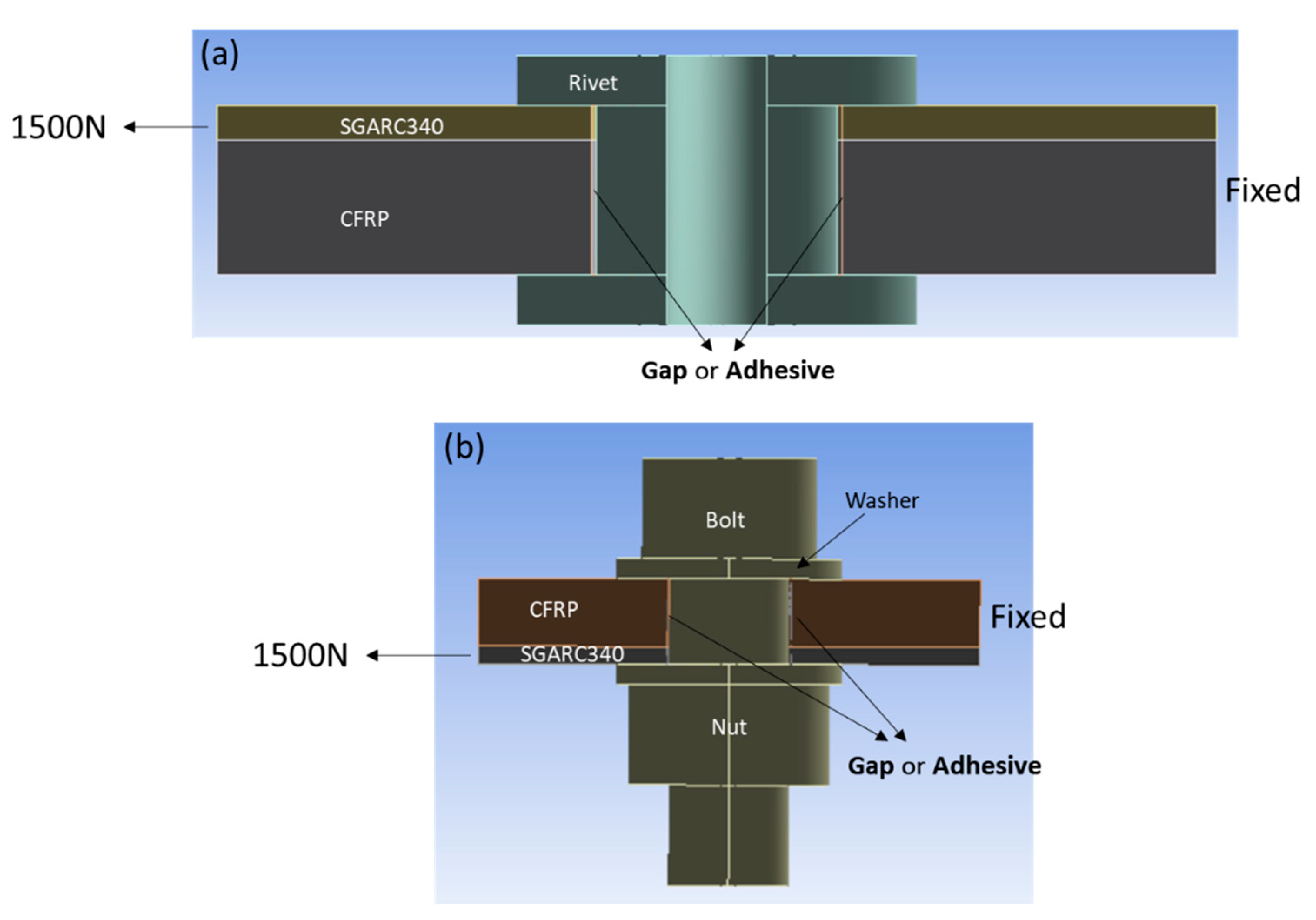
2.3. Numerical Analysis of Stress Distribution for the CFRP/Steel Specimens

To evaluate the stress distribution of mechanically bonded CFRP/steel composites during LSS tests, a finite element analysis was conducted using the ANSYS Mechanical software (2020 R2). Figure 2 shows the geometric models that reflect the mechanically bonded (rivet or bolt) CFRP/steel composite specimens.
To examine the effect of the adhesive, a model with the adhesive and a model with empty space instead of the adhesive were used. Moreover, in the case of bolts, a model without the washer was developed to examine the effect of the washer. The parameters of materials used for each analysis are listed in Table 2. In all simulation cases, the boundary conditions were set such that one side of the CFRP was fixed and one side of the steel was pulled with a force of 1500 N. Next, the stress exerted on the fasteners was examined.

3. Results and Discussion

3.1. Characteristics of LSS in Hybrid Bonding between CFRP/Steel with Clearance-Filling Effect
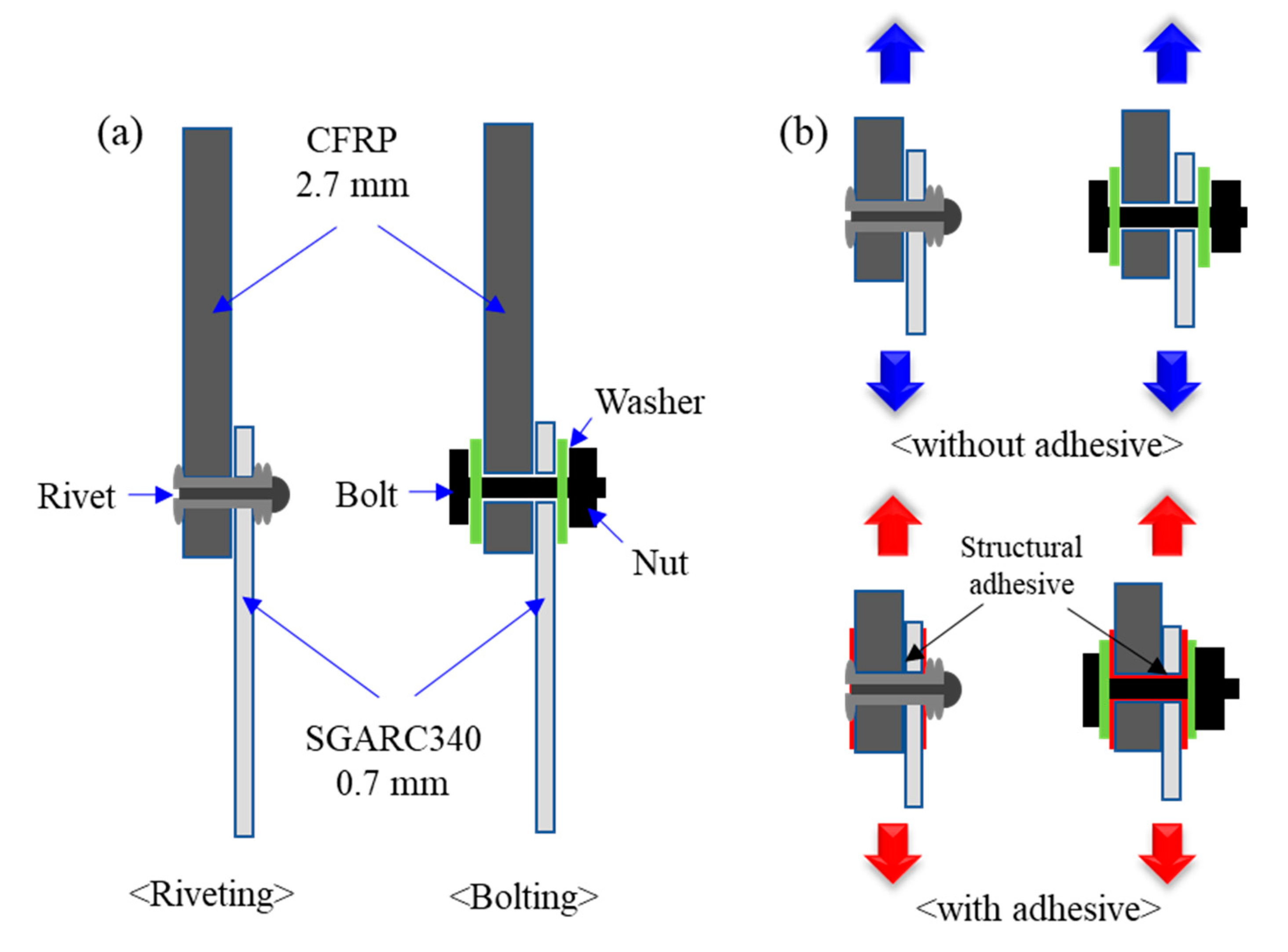
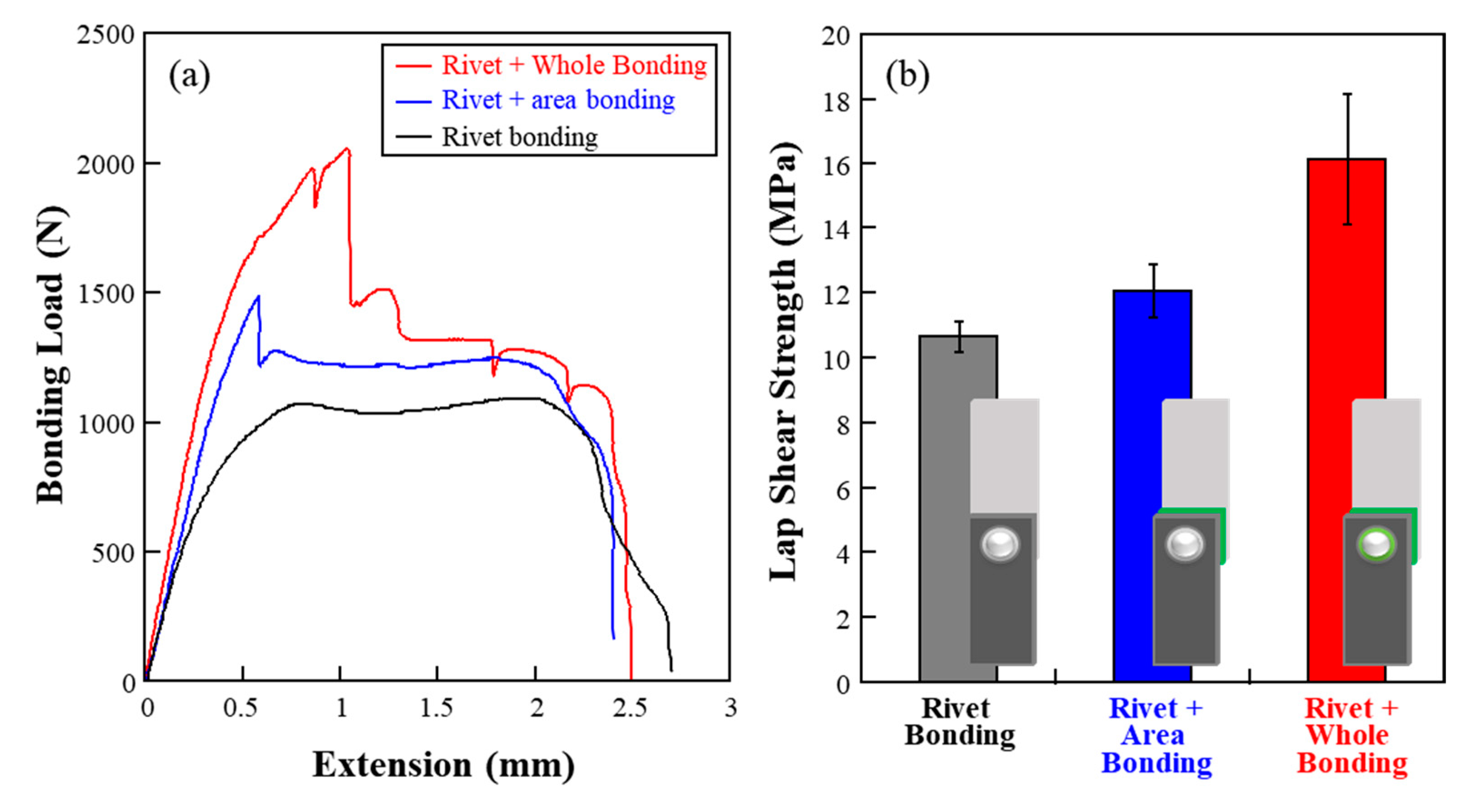
3.1.1. Riveting

Figure 3 shows the effect of adhesive when CFRP and steel are fastened with rivets. The LSS was evaluated for the following cases: riveting without the adhesive, applying the structural adhesive only to the contact surface, and applying the adhesive to both the contact surface and the clearance between materials and rivet. When only rivets were used, the rivet bent significantly and showed the lowest LSS value (10 MPa) among the three cases. When the structural adhesive was used on the adhesive surface along with the rivets, the LSS was 12 MPa, which was higher than that for rivets alone. This is because the structural adhesive increased the resistance in the shear direction of the adhesive surface, which in turn reduced the force transmitted to the rivet and improved the physical properties of LSS by 20%. When the adhesive was applied to all surfaces of the material in contact with the rivet, the adhesive strength increased to 16 MPa. This was a 50% improvement in LSS compared to the case where only the rivet was used. Thus, the structural adhesive not only showed resistance in the shear direction but also tightened the movement of the rivet, thereby reducing the stress transferred to the rivet during the test, resulting in a high LSS. In other words, strong bonding is possible only if the movement of the fastener can be minimized with additives such as structural adhesives during mechanical fastening. Figure 4 clarifies this explanation, showing the observations of the fractured surface of the specimen when only rivets were used and when the structural adhesive was applied to all contact surfaces. In all cases, the LSS tests demonstrate that fractures occur at the rivets. When only rivets were used, the rivets bent significantly and were crushed, gaining an oval shape instead of a perfect circle (Figure 4a). The reason for this is that the rivet tilted owing to the presence of a 2 mm clearance and then deformed under a significant load. However, when the structural adhesive was used, as shown in Figure 4b, it filled the clearance and prevented tilting of the fastener; consequently, the rivet was not significantly deformed.

3.1.2. Bolting

Figure 5 shows the results of evaluating the adhesive load according to the use of washer and structural adhesive when CFRP and steel were bonded by bolting. Type 1 denotes the case in which only bolts and nuts were used. The maximum lap shear load was approximately 2400 N, which was relatively low compared with other cases. However, the maximum lap shear load significantly increased to approximately 4200 N when the washer was used for both the bolt and nut (Type 4). Since the inclination of the bolt was constant when no adhesive was used, the strength improved because the deflection of the bolt decreased under the influence of the washer. Unlike riveting, in all cases of bolting, the adhesive strength was determined by the fracture of the steel. Therefore, the reduction in the deflection of the bolt prevented bending of the steel and minimized the pre-tension on the outer surface of the steel that resulted from bending; consequently, the bonding strength increased. When the washer was used on only one side as in Types 2 and 3, unlike the case in which the bolt and nut were used on both sides, the effect of preventing the bolt from bending reduced; consequently, the maximum lap shear load was lower than that when the washer was used on both sides. In particular, when a washer was used only on the bolt side, it had a significantly lower strength than when a washer was used on the nut side because the steel broke at the nut side; therefore, bending of the steel could be minimized by using a washer on the nut side. Consequently, the washer effectively prevented the bending of the bolt even if it was already tilted by the clearance.
In addition, the structural adhesive was used to investigate the change in adhesive strength according to the initial inclination of the bolt when all washers were applied. The red bar in Figure 5 shows its location. When only washers were fixed using the structural adhesive (Type 5), they showcased a similar level of maximum lap shear load with a slight increase of 100 N compared to Type 4 (without the structural adhesive). Therefore, no special effect was observed upon attaching the washer to the adhesive surface. However, the highest maximum lap shear load (4800 N) was obtained when the structural adhesive was used on the washer bonding and entire-bolt contact surfaces (Type 6). In Type 6, the clearance between the bolt and hole was filled with adhesive. Compared to the case in which only the bolts and nuts were used, the maximum shear load was approximately doubled. In other words, in mechanical fastening by bolting the CFRP and steel, the washer prevents bending of the steel, and the adhesive prevents the initial inclination of the bolt. This improves the mechanical fastening strength between the CFRP and steel. Figure 6 shows a photograph captured after an LSS test of different specimens according to the use of the washer and adhesive during bolting. It shows the angle change during deformation of the bolt thread based on the vertical and horizontal lines. When only the nuts and bolts were used as in Type 1, the largest angle change was observed compared to other cases. In Type 2, where a washer was used only on the bolt side, deformation of the bolt thread was slightly alleviated due to the effect of the bolt-side washer. However, the steel showcased a deformation similar to that observed in Type 1. This reconfirms that if there is no washer on the nut side, the metal can be significantly deformed. However, the thread deformation angles of Types 4 and 6 were 2.5° and 1°, respectively, which are the minimum levels in the LSS tests. In Type 4, bending of the steel was minimized by preventing the deformation of the bolt under the influence of the washer. In Type 6, in addition to the aforementioned reason, the deformation of bolt and steel was more effectively restricted by preventing the initial inclination of bolts through structural adhesives.

3.2. Riveting and Bolting in Hybrid Bonding between CFRP/Steel Composites

Figure 7 shows the problems that may occur during mechanical fastening between the CFRP and metal. As shown in Figure 7a, the blind rivet is a mechanical fastener that applies a bonding force to two or more different parts. It can advantageously fix the two base materials relatively easily, but an empty space inevitably exists between the rivet and hole. Moreover, the fracture of the joined dissimilar material mainly occurs in the rivet due to its weak strength. As the rivet breaks easily, the effect of the initial inclination of the rivet caused by the clearance is more critical to bonding strength than bolting. This phenomenon may cause one part to fall out, as shown in Figure 7a. The hole in the materials is pushed towards the fastener by the external force, causing the hole to gain an oval shape; moreover, the diameter increases. In this case, one part may sometimes be missing, as shown in Figure 7a. Therefore, filling the clearance with an adhesive in riveting effectively improves the clamping force compared to that in bolting. Figure 7b displays deformation behavior with bolts. Figure 5 and Figure 6 demonstrate that the washers and structural adhesive are important. In bolting, the final fracture does not occur in the bolt but rather in the steel. Consequently, filling the clearance with the adhesive is less effective than riveting. However, after minimizing the deformation of the steel with a washer, the washer prevents the initial bolt from tilting and clearly improves the adhesive strength. In this experiment, the mechanical fastening strength was observed based on the failure when using a metal with a tensile strength lower than that of CFRP. When the metal elongates easily, it deforms easily due to the initial inclination of the bolt. The washer prevents the deformation of these metals, and filling the clearance with the adhesive helps in preventing the initial tilting of bolt.

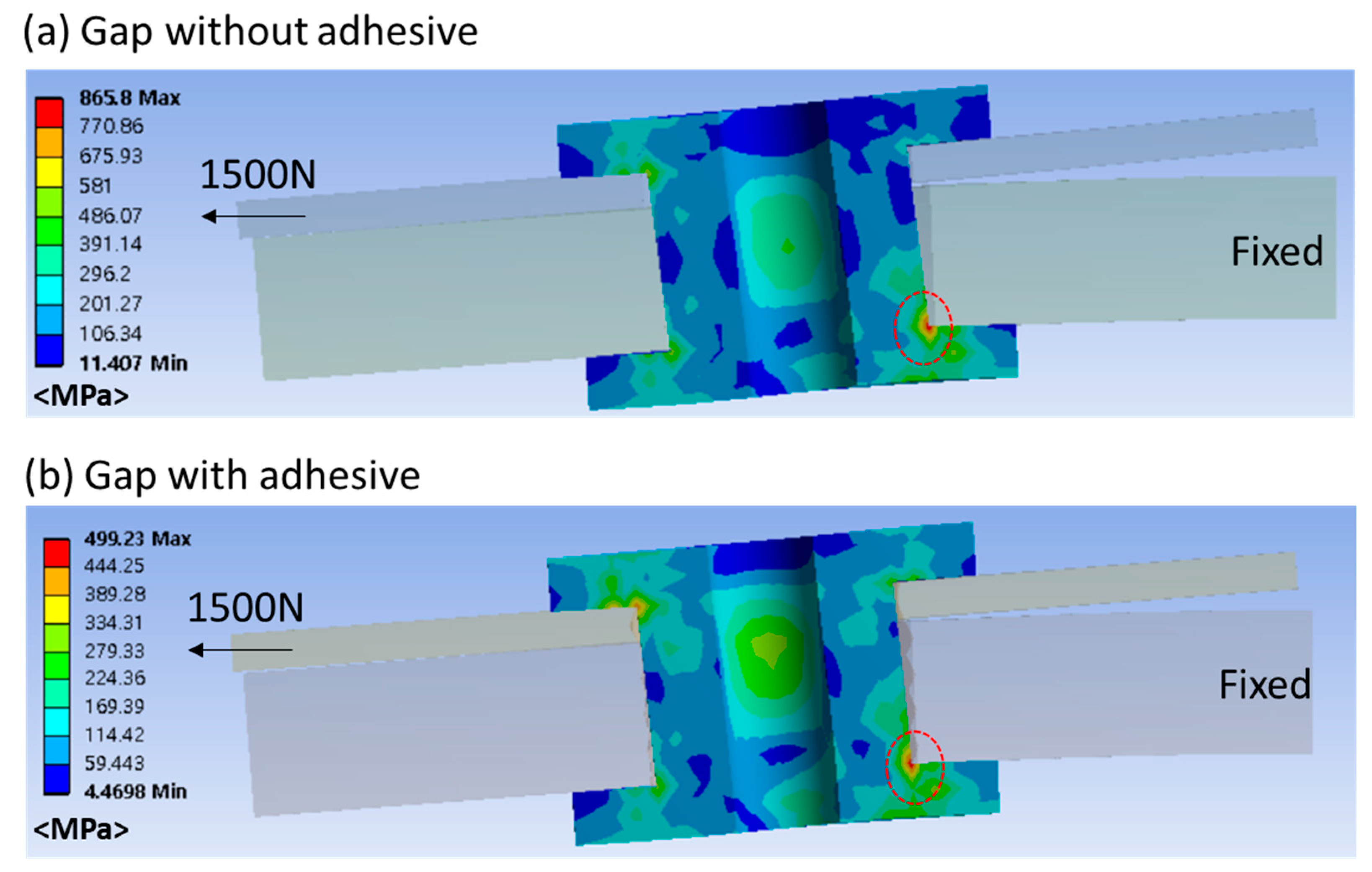
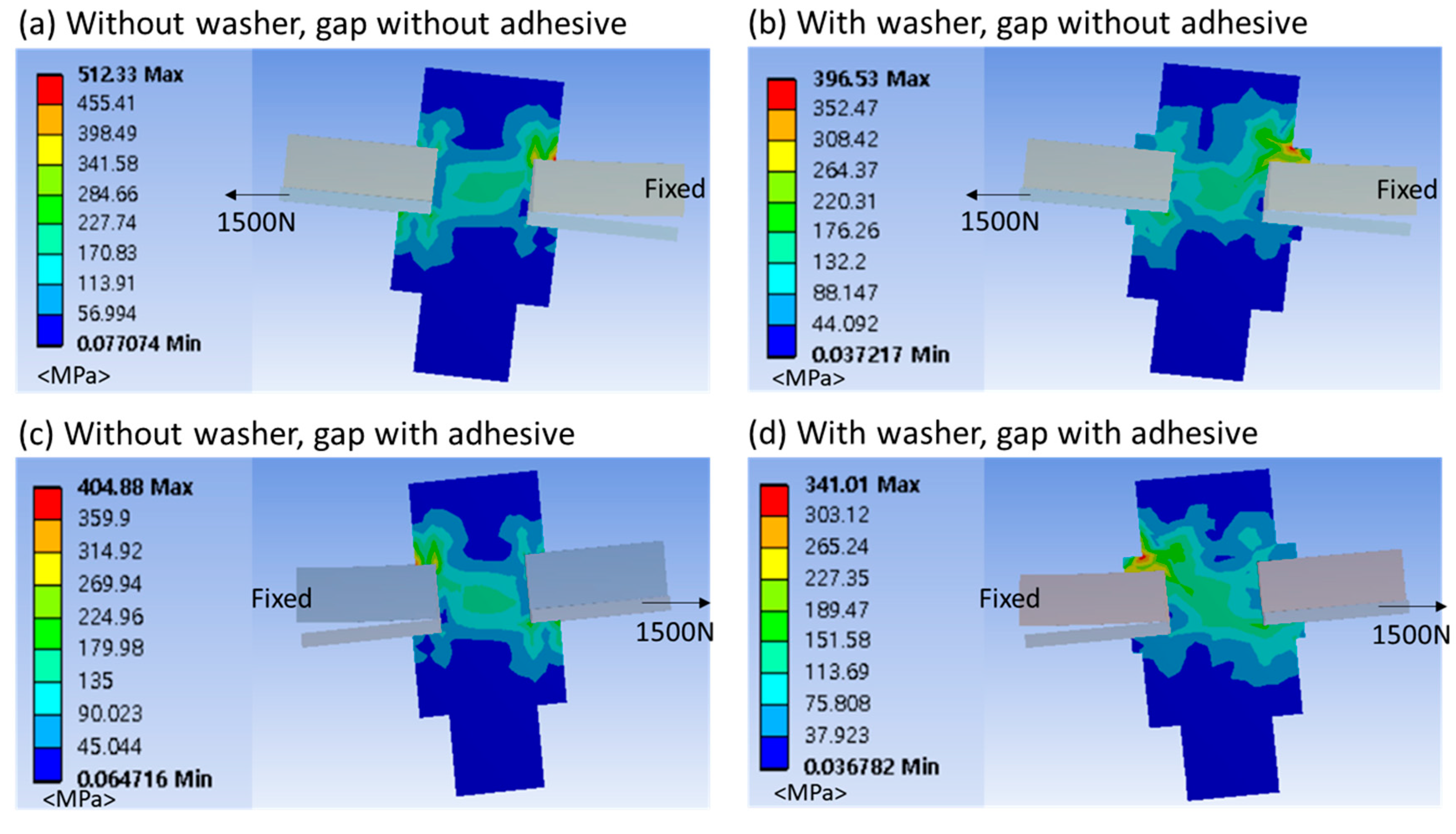
3.3. Numerical Analysis of Hybrid-Bonded CFPR/Steel Composites

An important condition identified by the aforementioned LSS tests of riveting and bolting is the filling of clearance that occurs during mechanical fastening. The effect of the initial inclination of the fastener due to the clearance on the deformation of the rivets and bolts was investigated through numerical analysis. Figure 8 shows the stress distribution of the rivet under an external force of 1500 N. In both cases, the highest stress was applied at the rivet end where the CFRP is located, which was consistent with the area where fracture occurred in the experiment. Note that the maximum stress in Figure 8a, in which the clearance was empty, was 866 MPa, whereas in Figure 8b, in which the clearance was filled with the adhesive, the maximum stress was 499 MPa, which shows that the stress on the rivet was reduced by 42% by using the adhesive. This is because the rivet was tilted by the clearance, and the stress at the edge significantly increased by the external force. Figure 8 also shows that the clearance being filled with structural adhesive to prevent the rivet from tilting can reduce the stress at the corner where the maximum stress is applied. Figure 9 shows the analytical results of the stress distribution on the bolt when an external force of 1500 N was applied. A comparison of Figure 9a,b confirms the effect of the washer in reducing the force exerted on the bolt. Figure 9b shows that the stress exerted on the bolt was reduced by distributing the stress using the washer; consequently, the deformation of the bolt was reduced even when the same external force was applied.
Figure 9c,d display the numerical analysis results when the structural adhesive was filled in the clearance without and with a washer, respectively. Figure 9c confirms the effect of preventing the bolt from tilting. Compared to the case in Figure 9a, the maximum stress applied to the bolt head reduced by approximately 20%. This result is similar to the case of using the washer. Figure 9d shows that the maximum stress exerted on the bolt reduced by 10% compared to that shown in Figure 9b. This indicates that even when the washer is used, the stress applied to the bolt can be reduced by preventing the bolt from tilting by filling the clearance. These results are consistent with the experimental results summarized in Section 3.1.

4. Conclusions

In this study, it was found that the initial inclination caused by the clearance is the one of the most important variables for improving the joint strength when joining CFRP and steel. The effect was analyzed through experimental and numerical analysis, and the main conclusions are summarized below.
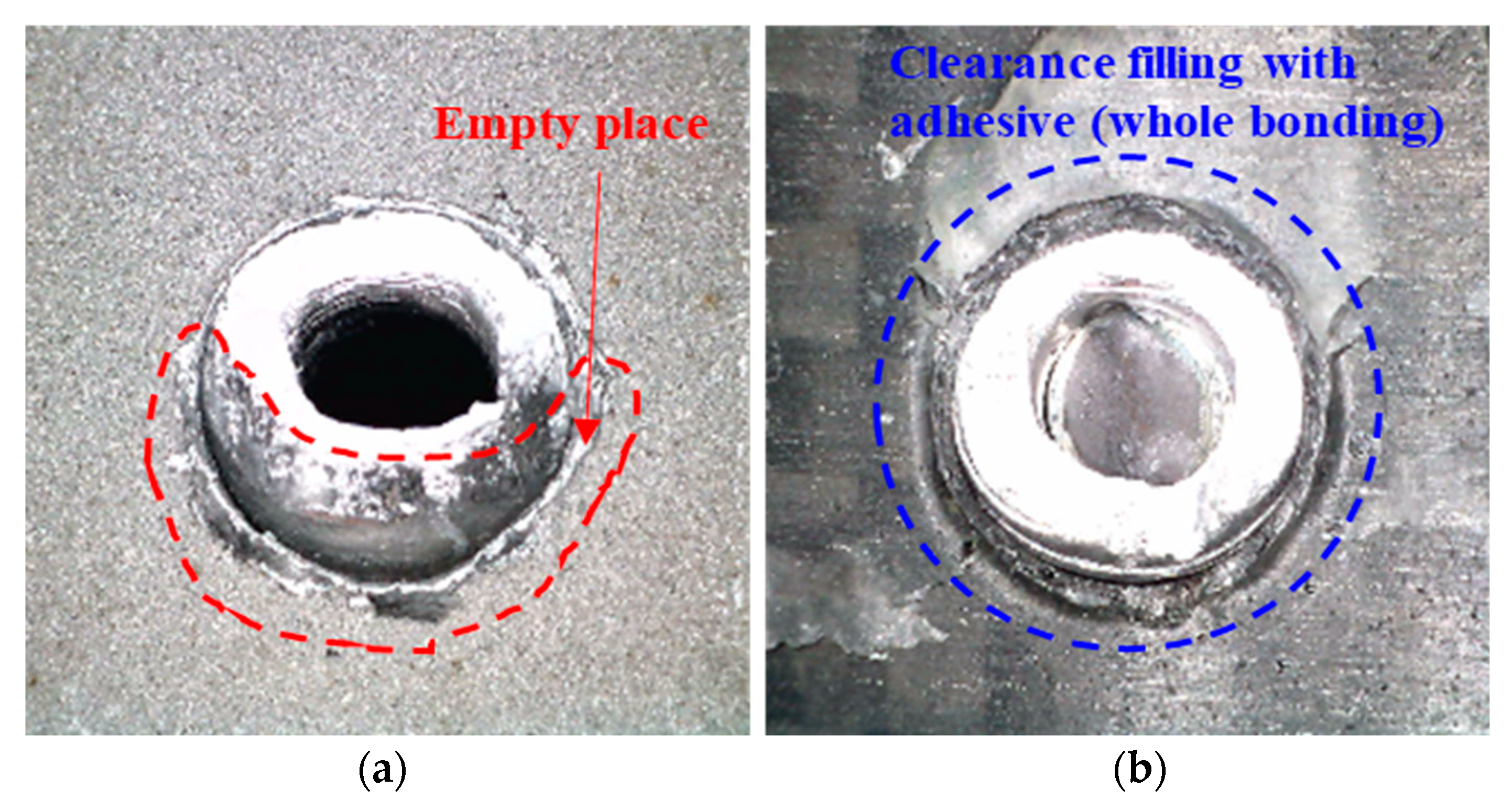
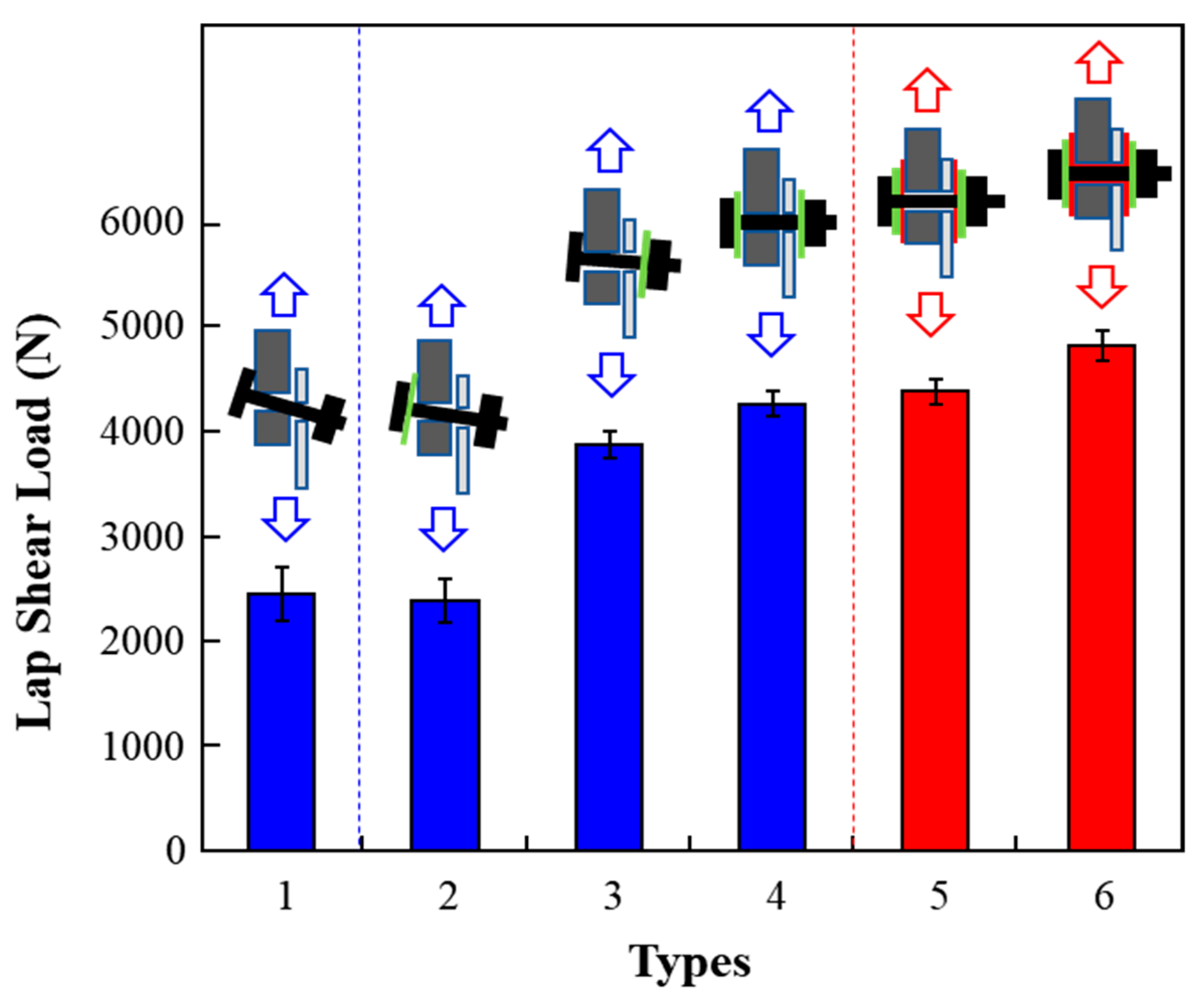
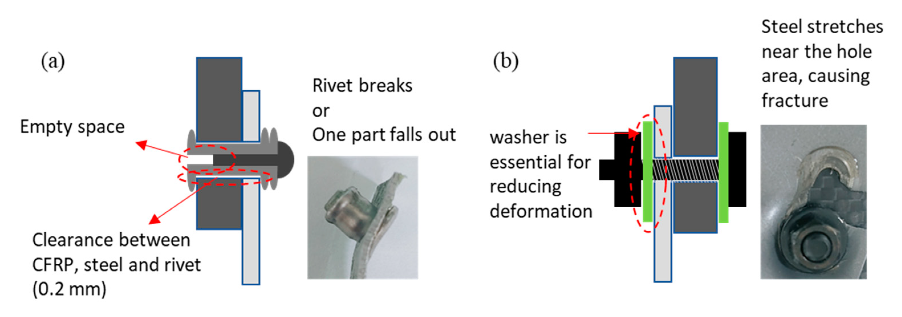
  • The clearance is inevitable when mechanically fastening dissimilar materials using rivets and bolts, and the clearance causes inclination of the fastener when an external force is applied.
  • When using structural adhesive, it is natural that the bonding strength increases due to the adhesion force, but in addition to this, the bonding strength improves due to the mechanism in which the fastener is prevented from tilting. In riveting, the clearance-filling effect showed an 33% improvement in LSS, even if the adhesion force caused by adhesive was excluded. In bolting, the bonding strength increased to twice the original value using the structural adhesive in the clearance, along with the washer to prevent the deformation of the steel. With the washer, the clearance-filling effect alone showed a 10% improvement in LSS.
  • The clearance-filling effect reduces the stress applied to the rivet and bolt when subjected to external force. So, this effect was significant in the case of the rivet that fractured in the fastener. Even in the case of the bolt, in which fracture did not occur in the fastener, the deformation of the bolt was reduced, resulting in less deformation of the steel where fracture occurred, leading to improved bonding strength.
  • Various cases were numerically analyzed to verify the above findings. In riveting, the maximum stress exerted on the rivet was reduced by clearance-filling, in accordance with the experimental results. Similar trends of numerical analysis results were obtained in bolting. One thing to note is that the use of washers in bolting had the same effect as the stress reduction on the bolt caused by the clearance-filling effect.
  • The results show the necessity of preventing the inclination of the fastener during mechanical fastening between dissimilar materials and reveal the mechanism that can help develop an efficient fastening method in the future.

Author Contributions

Conceptualization, H.-M.Y.; Validation, D.-J.K.; Formal analysis, J.P.; Investigation, J.P.; Data curation, D.-J.K.; Writing – original draft, H.-M.Y.; Visualization, D.-J.K.; Supervision, H.-M.Y. All authors have read and agreed to the published version of the manuscript.

Funding

This work was supported by the research grant of the Gyeongsang National University in 2022–2023, the Technology development Program (S3269454) funded by the Ministry of SMEs and Startups (MSS, Korea), and the National Research Foundation of Korea (NRF) grant funded by the Korea government (MSIT) (No. NRF-2021R1G1A1006606).

Institutional Review Board Statement

Not applicable.

Informed Consent Statement

Not applicable.

Data Availability Statement

Not applicable.

Conflicts of Interest

The authors declare no conflict of interest.

References

  1. Chung, D.D.L. A Review of Multifunctional Polymer-Matrix Structural Composites. Compos. Part B Eng. 2019, 160, 644–660. [Google Scholar] [CrossRef]
  2. González, C.; Vilatela, J.; Molina-Aldareguía, J.; Lopes, C.; LLorca, J. Structural Composites for Multifunctional Applications: Current Challenges and Future Trends. Prog. Mater. Sci. 2017, 89, 194–251. [Google Scholar] [CrossRef] [Green Version]
  3. Yang, Y.; Biscaia, H.; Chastre, C.; Silva, M.A. Bond characteristics of CFRP-to-steel joints. J. Constr. Steel Res. 2017, 138, 401–419. [Google Scholar] [CrossRef]
  4. Pan, Z.; Qiao, F.; Wang, M.; Wu, Z.; Ying, Z. A novel damage mechanism analysis of integrally braided CFRP and CFRP/Aluminum hybrid composite tube subjected to transverse impact. Mater. Des. 2021, 206, 109815. [Google Scholar] [CrossRef]
  5. Xu, L.Y.; Lu, J.; Li, K.; Hu, J. Experimental Study of CFRP Laser Surface Modification and Bonding Characteristics of CFRP/Al6061 Heterogeneous Joints. Compos. Struct. 2022, 283, 115030. [Google Scholar] [CrossRef]
  6. Moreira, R.D.F.; Moura, M.; Silva, F.; Rodrigues, J.; Silva, F.D.R. Fracture Characterization of a Bi-material Bonded Aluminum/CFRP Joints under Mixed-mode I + II Loading. Fatigue Fract. Eng. Mater. Struct. 2022, 45, 2215–2226. [Google Scholar] [CrossRef]
  7. Sun, Y.; Zhang, Y.; Long, H.; Sun, Y.; Zou, L.; Yang, X. Friction Stir Lap Welding for Dissimilar Materials of Aluminum Alloy and Carbon-Fiber-Reinforced Polyetherimide. Mater. Today Commun. 2022, 33, 104427. [Google Scholar] [CrossRef]
  8. Wang, S.; Xu, Y.; Wang, W.; Tian, Y.; Zhang, X.; Huang, H.; Zheng, D. Enhancing Interfacial Bonding in Friction Stir Lap Welding of Light Metal and Carbon Fiber Reinforced Polymer Composite. J. Manuf. Process. 2022, 83, 729–741. [Google Scholar] [CrossRef]
  9. Paliwal, I.; Ramji, M. A Detailed Study on the Damage Evolution and Failure Assessment of Single-Lap Hybrid Joints in CFRP Laminates under Tensile Loading. Compos. Struct. 2022, 299, 104427. [Google Scholar] [CrossRef]
  10. Jiang, L.; Dong, D.; Xiao, S.; Chen, D.; Yang, B.; Yang, G.; Zhu, T. Experiment and Simulation Study on Bonded, Bolted and Hybrid Bolted/Bonded Joints of Textile CFRP Using Bimodulus Constitutive Model. Int. J. Adhes. Adhes. 2022, 116, 103154. [Google Scholar] [CrossRef]
  11. Suo, H.; Wei, Z.; Zhang, K.; Deng, K.; Cheng, H.; Luo, B.; Li, H.; Wang, L.; Liang, B. Interfacial Wear Damage of CFRP/Ti-Alloy Single-Lap Bolted Joint after Long-Term Seawater Aging. Eng. Fail. Anal. 2022, 139, 106464. [Google Scholar] [CrossRef]
  12. Li, S.; Zhang, S.; Li, H.; Qin, X.; Wu, X.; Gui, L. Numerical and Experimental Investigation of Fitting Tolerance Effects on Bearing Strength of CFRP/Al Single-Lap Blind Riveted Joints. Compos. Struct. 2022, 281, 115022. [Google Scholar] [CrossRef]
  13. Ding, G.; Feng, P.; Wang, Y.; Ai, P. Novel Pre-Clamp Lap Joint for CFRP Plates: Design and Experimental Study. Compos. Struct. 2022, 302, 116240. [Google Scholar] [CrossRef]
  14. Kapidžić, Z.; Granados, D.; Arias, J.; Aguilera, M.; Rodríguez, J.; Callejas, J. Bolt Fatigue in CFRP Joints. Int. J. Fatigue 2022, 164, 107138. [Google Scholar] [CrossRef]
  15. Vorderbrüggen, J.; Köhler, D.; Grüber, B.; Troschitz, J.; Gude, M.; Meschut, G. Development of a Rivet Geometry for Solid Self-Piercing Riveting of Thermally Loaded CFRP-Metal Joints in Automotive Construction. Compos. Struct. 2022, 291, 115583. [Google Scholar] [CrossRef]
  16. Fink, A.; Camanho, P.P.; Andrés, J.M.; Pfeiffer, E.; Obst, A. Hybrid CFRP/titanium bolted joints: Performance assessment and application to a spacecraft payload adaptor. Compos. Sci. Technol. 2010, 70, 305–317. [Google Scholar] [CrossRef]
  17. Zhang, H.; Zhang, L.; Xu, C.; Liu, Z.; Zhu, P. Global Sensitivity Analysis of Mechanical Properties in Hybrid Single Lap Aluminum-CFRP (Plain Woven) Joints Based on Uncertainty Quantification. Compos. Struct. 2022, 280, 114841. [Google Scholar] [CrossRef]
  18. Jiang, H.; Ren, Y. CFRP-Patching Enhancement on Open-Hole CFRP Panel with Micro/Nanofillers-Modified Adhesive Interface: Experimental and Numerical Simulation. Compos. Sci. Technol. 2022, 218, 109180. [Google Scholar] [CrossRef]
  19. He, Z.; Luo, Q.; Li, Q.; Zheng, G.; Sun, G. Fatigue Behavior of CFRP/Al Adhesive Joints—Failure Mechanisms Study Using Digital Image Correlation (DIC) Technique. Thin-Walled Struct. 2022, 174, 109075. [Google Scholar] [CrossRef]
  20. Chen, Y.; Li, M.; Su, T.; Yang, X. Mechanical Degradation and Corrosion Characteri zation of Riveted Joints for CFRP/Al Stacks in Simulated Marine Environments. Eng. Fail. Anal. 2022, 137, 106382. [Google Scholar] [CrossRef]
  21. Wang, A.; Wang, Z.; Zhao, Y.; Chang, Z.; Shao, X.; Kang, Y. Fatigue Behaviour and Failure Mechanism of the Thin/Thick-Ply Hybrid Laminated Composite Bolted Joints. Compos. Struct. 2022, 295, 115636. [Google Scholar] [CrossRef]
  22. Korbel, A. Effect of Aircraft Rivet Installation Process and Production Variables on Residual Stress, Clamping Force and Fatigue Behaviour of Thin Sheet Riveted Lap Joints. Thin-Walled Struct. 2022, 181, 110041. [Google Scholar] [CrossRef]
  23. Geier, N.; Póka, G.; Jacsó, Á.; Pereszlai, C. A Method to Predict Drilling-Induced Burr Occurrence in Chopped Carbon Fibre Reinforced Polymer (CFRP) Composites Based on Digital Image Processing. Compos. Part B Eng. 2022, 242, 110054. [Google Scholar] [CrossRef]
  24. Xu, J.; Yin, Y.; Davim, J.P.; Li, L.; Ji, M.; Geier, N.; Chen, M. A Critical Review Addressing Drilling-Induced Damage of CFRP Composites. Compos. Struct. 2022, 294, 115594. [Google Scholar] [CrossRef]
  25. Zhou, J.; Shi, Y.; Zuo, Y.; Shan, C.; Gu, Z. Experimental Investigation into Influences of Z-Pin and Deltoid on Structural Properties and Damage Tolerance of CFRP T-Joints. Compos. Part B Eng. 2022, 237, 109875. [Google Scholar] [CrossRef]
  26. Ouyang, Y.; Chen, C. Research Advances in the Mechanical Joining Process for Fiber Reinforced Plastic Composites. Compos. Struct. 2022, 296, 115906. [Google Scholar] [CrossRef]
  27. Song, Y.; Cao, H.; Zheng, W.; Qu, D.; Liu, L.; Yan, C. Cutting Force Modeling of Machining Carbon Fiber Reinforced Polymer (CFRP) Composites: A Review. Compos. Struct. 2022, 299, 116096. [Google Scholar] [CrossRef]
  28. Wu, J.; Chen, C.; Chen, C. Experimental Investigation of High Impact Polystyrene/Metal Self-piercing Riveted Joint. Polym. Adv. Technol. 2022, 33, 2221–2230. [Google Scholar] [CrossRef]
  29. Lim, Y.; Jun, J.; Leonard, D.; Li, Y.; Chen, J.; Brady, M.; Feng, Z. Study of Galvanic Corrosion and Mechanical Joint Properties of AZ31B and Carbon-Fiber–Reinforced Polymer Joined by Friction Self-Piercing Riveting. J. Magnes. Alloy. 2022, 10, 400–410. [Google Scholar] [CrossRef]
  30. Granju, J.L.; Balouch, S.U. Corrosion of steel fibre reinforced concrete from the cracks. Cem. Concr. Res. 2005, 35, 572–577. [Google Scholar] [CrossRef]
  31. Ren, X.; Sherif, M.; Wei, Y.; Lyu, Y.; Sun, Y.; Ozbulut, O. Effect of Corrosion on the Tensile and Fatigue Performance of CFRP Strand Sheet/Steel Double Strap Joints. Eng. Struct. 2022, 260, 114240. [Google Scholar] [CrossRef]
  32. Schanz, J.; Meinhard, D.; Dostal, I.; Riegel, H.; De Silva, A.; Harrison, D.; Knoblauch, V. Comprehensive Study on the Influence of Different Pretreatment Methods and Structural Adhesives on the Shear Strength of Hybrid CFRP/Aluminum Joints. J. Adhes. 2022, 98, 1772–1800. [Google Scholar] [CrossRef]
  33. Yang, M.; Kainuma, S.; Xie, J.; Liu, W.; Liu, Y. Bond Behavior between CFRP and Corroded Steel Plate Associations with Surface Treatments. Compos. Part B Eng. 2022, 246, 110280. [Google Scholar] [CrossRef]
  34. Jabbari, M.; Raftery, G.; Lim, J. Environmental Durability of Epoxy-Bonded CFRP-to-Steel Joints in Mode I Fracture. Int. J. Adhes. Adhes. 2022, 112, 103034. [Google Scholar] [CrossRef]
  35. Gómez, J.; Barris, C.; Jahani, Y.; Baena, M.; Torres, L. The Effect of Steady and Cyclic Environmental Conditions on the Tensile Behaviour of a Structural Adhesive under Sustained Loading. Compos. Struct. 2022, 286, 115287. [Google Scholar] [CrossRef]
  36. Moreira, R.; de Moura, M.; Silva, F.; Reina, J. Mixed-Mode I+II Fatigue/Fracture Characterisation of Bi-Material Aluminium/CFRP Bonded Joints. Compos. Part B Eng. 2022, 246, 110240. [Google Scholar] [CrossRef]
  37. Cristiani, D.; Falcetelli, F.; Yue, N.; Sbarufatti, C.; Di Sante, R.; Zarouchas, D.; Giglio, M. Strain-Based Delamination Prediction in Fatigue Loaded CFRP Coupon Specimens by Deep Learning and Static Loading Data. Compos. Part B Eng. 2022, 241, 110020. [Google Scholar] [CrossRef]
  38. Wojtczak, E.; Rucka, M. Damage Imaging Algorithm for Non-Destructive Inspection of CFRP/Steel Adhesive Joints Based on Ultrasonic Guided Wave Propagation. Compos. Struct. 2022, 297, 115930. [Google Scholar] [CrossRef]
  39. Mu, W.-L.; Xu, Q.-H.; Na, J.-X.; Wang, H.; Tan, W.; Li, D.-F. Influence of Temperature and Humidity on the Fatigue Behaviour of Adhesively Bonded CFRP/Aluminium Alloy Joints. J. Adhes. 2022, 98, 1358–1376. [Google Scholar] [CrossRef]
  40. Silva Neto, A.; Cruz, D.T.L.D.; Ávila, A.F. Nano-modified adhesive by graphene: The single lap-loint case. Mater. Res. 2013, 16, 592–596. [Google Scholar] [CrossRef]
  41. Ramaswamy, K.; O’Higgins, R.; McCarthy, C. Impact Damage Tolerance and Residual Performance of Novel Interlocked-Hybrid Structural Joints. Compos. Part B Eng. 2022, 241, 109996. [Google Scholar] [CrossRef]
Figure 1. Schematic of the mechanical bonding between CFRP and steel plates: (a) riveting/bolting and (b) hybrid mechanical bonding with adhesive.
Applsci 13 04332 g001
Figure 2. Geometric models for numerical analysis: (a) rivet and (b) bolt.
Applsci 13 04332 g002
Figure 3. LSS results of CFRP/steel composites using riveting: (a) Load-extension graph and (b) LSS results in each case.
Applsci 13 04332 g003
Figure 4. Fractured surface of LSS specimens depending on whether or not adhesive was used: (a) rivet only and (b) both rivet and adhesive.
Applsci 13 04332 g004
Figure 5. Lap shear load of the CFRP and steel joined by bolting in different cases.
Applsci 13 04332 g005
Figure 6. Deformation of the joining segment with the washer and adhesive. (red line: vertical and horizontal axis, blue line: axis by bolt thread).
Applsci 13 04332 g006
Figure 7. Deformation of the washer and adhesive joint: (a) riveting and (b) bolting.
Applsci 13 04332 g007
Figure 8. Numerical analysis results for riveting: (a) clearance without and (b) with the adhesive.
Applsci 13 04332 g008
Figure 9. Numerical analysis for bolting cases: (a) clearance without an adhesive as well as (a) without and (b) with the washer; and clearance with an adhesive as well as (c) without and (d) with the washer.
Applsci 13 04332 g009
Table 1. Experimental cases.
RivetingBolting
Type 1Just rivetingJust bolting
Type 2Riveting + contact area bondingBolting + washer on the bolt-head side
Type 3Riveting + whole area bondingBolting + washer on the nut side
Type 4-Bolting + washers on the bolt-head and nut side
Type 5-Bolting + washers on the bolt-head and nut side + washer contact area bonding
Type 6-Bolting + washers on the bolt-head and nut side + whole area bonding
Table 2. Material parameters used for numerical analysis.
MaterialDensityYoung’s ModulusPoisson’s Ratio
RivetAl20172770 kg/m372 GPa0.22
BoltStainless steel7750 kg/m3193 GPa0.31
CFRPCFRP1540 kg/m353.5 GPa
(In-plane)
0.32
(In-plane)
9.6 GPa
(Out-of-plane)
0.03
(Out-of-plane)
SGARC340Structural steel7850 kg/m3200 GPa0.3
AdhesiveAdhesive1200 kg/m30.163 GPa0.12
Disclaimer/Publisher’s Note: The statements, opinions and data contained in all publications are solely those of the individual author(s) and contributor(s) and not of MDPI and/or the editor(s). MDPI and/or the editor(s) disclaim responsibility for any injury to people or property resulting from any ideas, methods, instructions or products referred to in the content.

