Article

The Modular Gait Design of a Soft, Earthworm-like Locomotion Robot Driven by Ultra-Low Frequency Excitation

School of Aerospace Engineering and Applied Mechanics, Tongji University, No. 100, ZhangWu Rd, Shanghai 200092, China
*
Author to whom correspondence should be addressed.
Appl. Sci. 2023, 13(4), 2723; https://doi.org/10.3390/app13042723
Submission received: 1 February 2023 / Revised: 15 February 2023 / Accepted: 18 February 2023 / Published: 20 February 2023

Abstract

:
In complex and extreme environments, such as pipelines and polluted waters, gait programming has great significance for multibody segment locomotion robots. The earthworm-like locomotion robot is a representative multibody bionic robot, which has the characteristics of low weight, multibody segments, and excellent movement performance under the designed gait. The body segment cell can realize large deformation under ultra-low frequency excitation. The multibody segment robot can locomote under ultra-low frequency excitation with appropriate shifts. In this paper, a modular gait design principle for a soft, earthworm-like locomotion robot is proposed. The driven modules defined by modular gait generation correspond to the peristaltic wave transmissions of the excitation in the robot for different modular gait modes. A locomotion algorithm is presented to simulate the locomotion of the earthworm-like robot under different locomotion gaits. Moreover, the locomotion speeds are obtained for different modular gait modes. The results show that locomotion speed is related to the original state of the body segments and modular gaits. As the initial actuated segments and driven modules (which correspond to the excitation frequency and shift) increase, faster movement speeds can be realized, which resolves the speed saturation of the earthworm-like robot. The proposed modular gait design method gives a new gait generation principle for the improvement of the locomotion performance of soft, earthworm-like robots.

1. Introduction

Wheeling, crawling, and legging are the most common movement modes for land-based locomotion robots [1,2,3]. In a water environment, wheeling and legging movements always fail. However, crawling can move forward effectively. In environments such as danger searching, industrial inspection, and internal medical treatment, biomimetic crawling locomotion robots have been successfully applied due to their strong adaptability and controllability [4,5]. The earthworm-like robot, which is servomotor driven, is designed to achieve horizontal and vertical in-pipe locomotion [6,7,8,9]. The earthworm-like robot, with two servomotors driven per segment, can realize planar locomotion [10]. Further, when utilizing a Kirigami design to enhance anchoring, the earthworm-like robot achieves movement in multiple environments [11]. In order to increase the environmental adaptability of the bionic earthworm robot, a compliant, modular mesh worm robot with steering is made, increasing the possible degree of freedom and realizing turning movement [12,13]. The most important ability of a locomotion robot with multi-segment is movement ability, including speed, depending on the designed gait [14]. Therefore, the investigation and design method for locomotion gaits of a locomotion robot can significantly improve movement performance.
The receding peristaltic wave is an important feature of earthworm movement, while the gait is the manifestation of peristaltic waves for the earthworm-like robot. It discovers that the average speed and anchor effectiveness can be improved by adjusting the gait parameters [15] based on a dynamic model [16]. In the proposed gait, as reference [15], the earthworm-like locomotion robot is composed of three body segment states: anchoring, driving, and relaxing. The phase difference gait is the optimal gait of the locomotion robot through theoretical analysis [17,18]. With the identical phase-difference-driven mode, the maximum average speed of the robot can be obtained [15]. Via the relevant experiments, the relationship between the average speed and the phase difference of each segment of a gait can be verified [18]. However, with an increase in the number of body segments, the maximum average speed displays a saturation phenomenon.
The gait design is related to the programming and driving performance of the robot actuators. According to the observation of earthworm movement experiments in [19,20], earthworms can stretch multiple body segments simultaneously via their muscles as they move [21]. In order to simulate the actuation and deformation of the muscles, variable soft actuators [22,23,24], such as pneumatically-driven [5,25,26] and dielectric elastomer actuators [27], have been proposed and manufactured for earthworm-like locomotion robots. In reference [28], a pneumatically driven earthworm-like soft robot is proposed, mimicking the deformation and movement of an earthworm. In nonhomogeneous environments, the robot can deform for lateral bending and buckling by utilizing pneumatically driven actuators [29]. In addition, when considering that the necessary anchoring section can improve movement performance, the pneumatic actuator is used to induce friction by adjusting the contact between the robot and the environment [30]. Because the pneumatic actuator is powered by pumping/compressing air, the response time of the actuator is usually longer than an electric actuator [31]. In order to obtain a faster response for the programming of the body segment, dielectric elastomers [32] have been widely utilized as actuators in robots [27,33,34]. According to the actuation principle of the dielectric elastomer described in references [35,36,37], a dielectric elastomer actuator is proposed for application in a micro, earthworm-like robot [38]. According to the different designs of dielectric elastomer actuators, dielectric elastomer actuators can realize different deformations for the robot segments [33]. For instance, in reference [39], the dielectric elastomer actuator is embedded into the continuous cylindrical robot body, and silicone fiber is laid to avoid compression, and with this design method, the movement speed reaches 28 mm/min; in reference [40], reciprocating locomotion using different amplitudes and frequencies (of tilted bristles) induced by the dielectric elastomer actuators is generated to improve the forward speed. In order to supply a larger actuation force, dielectric elastomer films are stacked in layers [41]. Moreover, it is discovered that by attaching a prestretched dielectric elastomer to a polyethylene terephthalate frame, the dielectric elastomer with a polyethylene terephthalate frame can be considered as the body segment in a soft robot, which represents the structure-actuation integrated design [42]. Gu et al. connect three dielectric elastomer actuators within a soft, locomotion robot with three body segments. For the structure-actuation integrated design, the average speed is 5.3 mm/s [43]. Lu et al. improve the minimum energy structure with the dielectric elastomer actuator and increase the actuator body segments, which increases the movement speed to 11.5 mm/s [44]. The above researches mainly focus on the movement realization of earthworm-like locomotion robots with soft actuators without investigating the relationship between locomotion performance and gait.
In reference [15], a gait theory for a bionic earthworm-like robot is proposed. It is discovered that, for an increase in the driven segments, the saturation phenomenon for the maximum average speed occurs. The soft actuator has the advantages of large deformation and low weight, which can greatly reduce the weight of the robot and improve the movement speed. Fortunately, since the dielectric elastomer actuator has the characteristics of low weight and fast actuation, the synchronous driven of multiple segments can be achieved. Thus, the dielectric elastomer is selected as the soft actuator in this work. Periodic electrical signals are applied to the soft segments to realize the reciprocating expansion of the segments. A segment cell is a vibration-driven system. The vibration-driven is used in the capsule robot, and the effective movement of the system is realized [45]. Based on the vibration-driven, the dielectric elastomer robot realizes bidirectional movement [46]. The cell phone vibrators are employed for the vibration-driven small robot Rizeh to reduce the cost of the robot [47]. A vibration-driven robot with a time-varying stiffness structure is proposed to reveal the nonlinear driven mechanism of a vibration-driven system [48]. The vibration-driven can also be applied to multisegment, earthworm-like locomotion robots. The earthworm-like robot can move forward under vibration excitation [49]. The driven mode determines the movement of the robot. Gait design can provide different movement modes. In order to improve the movement speed of the earthworm-like robot, it is very critical to investigate the gait of the earthworm-like robot under vibration-driven movement.
By designing the gait, the robot can move effectively under ultra-low frequency excitation. Therefore, by combining the deformation characteristics of a soft actuator, a gait design for a soft, earthworm-like robot is proposed in this paper. The driven module modes in this study are bio-inspired by earthworms. In the driven module, a gait generation principle is proposed for different driven wave transmission modes. The modular gait methods improve the locomotion speed of the robot under ultra-low frequency excitation. This reveals that only the driven wave frequency and amplitude affect locomotion speed. Moreover, as the failure of an individual segment in a driven module occurs, locomotion can still be guaranteed due to the driven module design. Numerical simulations for different cases of generated gaits for different driven modules can be used to verify the modular driven design that can break through the saturation phenomenon of locomotion speed. For the proposed driven module design principle, the average locomotion speed is proportional to the number of actuated body segments for the gait of a driven module. The modular gait design method proposed in this paper provides a new idea for the movement strategy of multisegment robots. More importantly, it provides an effective gait design method for special robots, such as carrier robots or robots with partially driven segment failure.
The rest of the paper is structured as follows: in Section 2, the deformation of the actuator is derived, and a description of the driven module is presented. Gait generation algorithms and cases are demonstrated in Section 3. The locomotion of the soft, earthworm-like robot based on the soft actuators is simulated and analyzed in Section 4. The conclusion is given in Section 5.

2. Deformation and State Description of a Segment

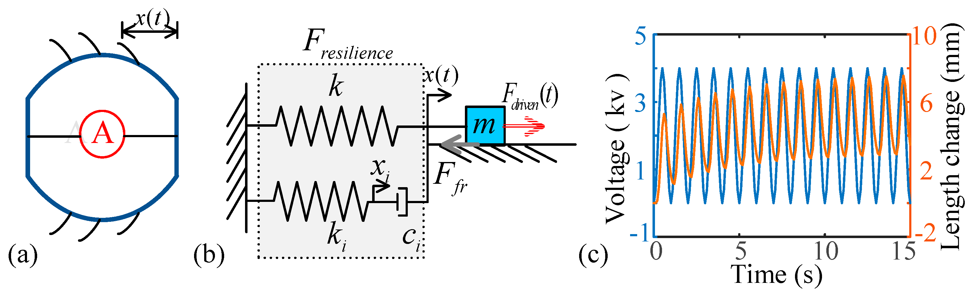
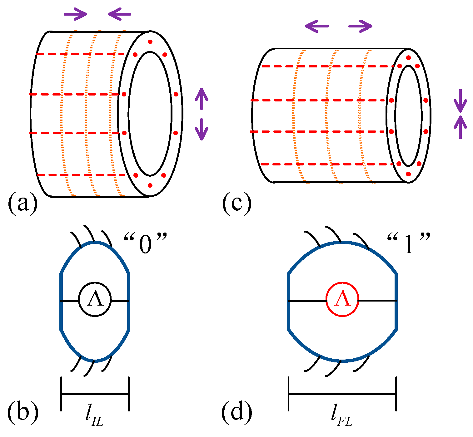
2.1. Segment Deformation

The dielectric elastomer actuator can deform the body segment under the action of periodic excitation voltage [43]. Figure 1 shows the model schematic diagram for the deformed body segment driven by the dielectric elastomer actuators. When the tail of the body segment is fixed, the displacement of the body segment head is assumed as x(t), as shown in Figure 1a. The simplification model of the body segment is obtained, as shown in Figure 1b. F d r i v e n ( t ) is the ultra-low frequency excitation. The body segment can realize reciprocating deformation under ultra-low frequency excitation. We refer to the results in reference [50], where four viscoelastic-spring components accurately describe the dynamic characteristics of the dielectric elastomer actuators.
In the simplified model of one body segment with a dielectric elastomer actuator, as Figure 1b, F d r i v e n ( t ) is the ultra-low frequency excitation. The mass of the body segment is assumed to be equivalent to the lumped mass m; the equivalent stiffness of the dielectric elastomer actuator is given as ki; and the equivalent viscous coefficient is given as ci (i = 1,2,3,4).
The frictional resistance is defined as Ffr, depending on the viscous forces. The ultra-low frequency excitation Fdriven(t) drives the dielectric elastomer actuator. The dynamic model of the body segment is expressed as
x ¨ = 1 m k x + i = 1 4 k i x i + F f r + 1 m F d r i v e n ( t ) , k i x i = c i x ˙ x ˙ i ,   i = 1 , 2 , 3 , 4 , F f r = ζ s i g n x ˙ , F d r i v e n ( t ) = V ( t ) 2 a x + b .
Fixing the parameters is the same as the values in reference [46]; for the excitation voltage V(t), the deformation of the body segment x can be calculated from Equation (1). As the excitation voltage is V ( t ) = 2 ( sin ( 2 π t π / 2 ) + 1 ) , the deformation of the body segment is shown in Figure 1c. In Figure 1c, the deformation of the body segment stays in periodic deformation under periodic excitation voltage. For the periodic deformation of the body segment, the locomotion of the earthworm-like robot can be realized.
According to the deformation of each segment x(t), the body length l(t) after deformation can be expressed as
l ( t ) = l 0 + x ( t )
where l0 is the original length of each body segment.

2.2. The State Definition of a Segment

The driven muscle groups for earthworms are composed of longitudinal muscles and circumferential muscles. For each segment, a schematic diagram of muscle distribution is shown in Figure 2a,c. The red dotted lines represent the longitudinal muscles, which are distributed along the parallel direction of the segment. The solid yellow lines represent the circumferential muscles, which are distributed along the circumference of the segment. When a segment of the earthworm is in a contracted state, the circumferential muscles elongate and the longitudinal muscles contract, as shown in Figure 2a; this is defined as the initial state. The original length of the body is defined as lIL, as shown in Figure 2b, and the state of the nonactuated segment is defined as “0”. When a body segment of the earthworms is in the elongated state, the longitudinal muscles elongate and the circumferential muscles contract, as shown in Figure 2c. The elongation state of the body segment is defined as the actuated state, defined as “1”. After the segment is driven, its length reaches the maximum value: lFL, as shown in Figure 2d.

2.3. The Definition of Driven Module

The alternate contraction of muscles realizes the expansion and contraction of the body segment for locomotion. Due to the advantages of the dielectric elastomer actuator, such as low weight and fast actuation, several adjacent body segments can elongate at the same time. When considering the requirements for locomotion speed, the segments are assumed to be actuated simultaneously. The simultaneously actuated segments are regarded as a module. We call the transmission mode of the simultaneously actuated segments as modularization design. The modularization driven could improve robot locomotion speed, which breaks the speed saturation phenomenon, as reference [15]. In this study, two cases of the driven module are proposed to investigate the locomotion performance of the soft, earthworm-like robots. In one case, multiple actuated body segments are continuously distributed and transmitted backward as one driven module, which we define as an unbroken driven module (U-DM). In the second case, there are nonactuated segments in one driven module, which we define as a broken driven module (B-DM), because of the easily broken characteristic of the soft actuator.

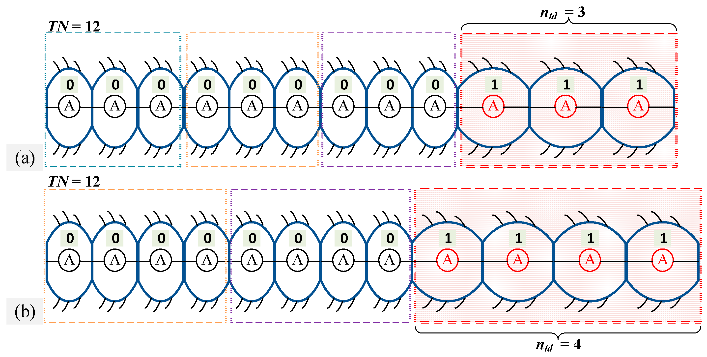
2.3.1. Unbroken Driven Module

For the U-DM, several adjacent segments are synchronously actuated. The receding peristaltic wave is transmitted as a combination of several actuated segments. In a multiple-segment robot with TN segments, the number of actuated body segments is ntd for one U-DM. Thus, for this case, there are two adjustable driven parameters, which are the number of the driven modules, k, and the number of actuated body segments in one driven module, ntd. The gait parameters in the earthworm-like robot with the U-DM satisfy the following conditions:
T N ( k + 1 )   n t d , n t d 1 ,   k 1 .
Figure 3 shows two examples of the initial gait distribution of the U-DM for a 12-segment earthworm-like robot. In Figure 3a, the number of actuated segments is ntd = 3, and in Figure 3b, the number of actuated segments is ntd = 4. For the U-DM, the segments are actuated together in one driven module. Therefore, there is only one initial modular gait distribution.

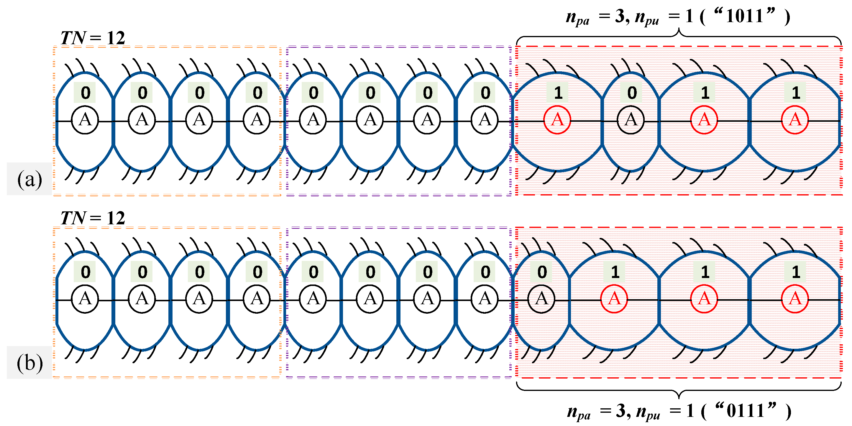
2.3.2. Broken Driven Module

As there can exist failed body segments in one driven module, the failed segments cannot deform. This case is defined as the B-DM. In a B-DM, the number of body segments is np, including the actuated segments, npa, and nonactuated segments, npu. Thus, this has the condition of n p = n p a + n p u . For the earthworm-like robot with the TN body segments, there are three independent adjustable parameters as the number of driven modules, k, actuated segments, npa, and nonactuated segments, npu. In the B-DM, all the gait parameters satisfy the following conditions:
T N k   n p ,   n p = n p a + n p u , n p a 1 ,   n p u 1 , k 1 .
For a driven module with np segments, the number of initial modular gait distributions with the B-DM is 2n − 2. For example, for a B-DM with four segments, there are 14 initial modular gait distributions that satisfy the conditions (4). Figure 4 shows two examples of initial gait distributions for the B-DM in a 12-segment earthworm-like robot. Figure 4a,b show two different initial gait distributions. In Figure 4a, we assume that a broken body segment (“0”) in one of the driven modules is not at the boundary of the driven module. The broken body segment “0” is at the boundary of the driven module, as shown in Figure 4b. In practical application, the distribution of the nonactuated body segment “0” of one driven module can be designed according to the required operating conditions.
The numbers of the actuated segments in Figure 3a and Figure 4b are the same, and the actuated segments are distributed continuously. However, the gait transmission is integrally transmitted in the form of the driven modules for the modular gait. The transmission mode of the driven module affects the locomotion performance of the earthworm-like robot.

3. Modular Gait Generation Principle

For the earthworm-like robot, the initial state of the gait is set to satisfy the transmission principle with a receding peristaltic wave. In the initial state of the earthworm-like robot, the head module is assumed to always be in the actuated state. For locomotion, the driven module may transmit in two modes for the nonfolded or folded waves. Here, we will give the transmission modes of the receding peristaltic wave on the driven module. One mode is the driven module waves without overlapping in the process of transmission. For the modular gait without any overlapping, the transmission mode is defined as the modular gait I (MG-I). The other mode is a driven module waves with overlapping in the transmission process. For the modular gait with overlapping, the relevant gait for locomotion is defined as modular gait II (MG-II).

3.1. Driven Module Waves without Overlapping

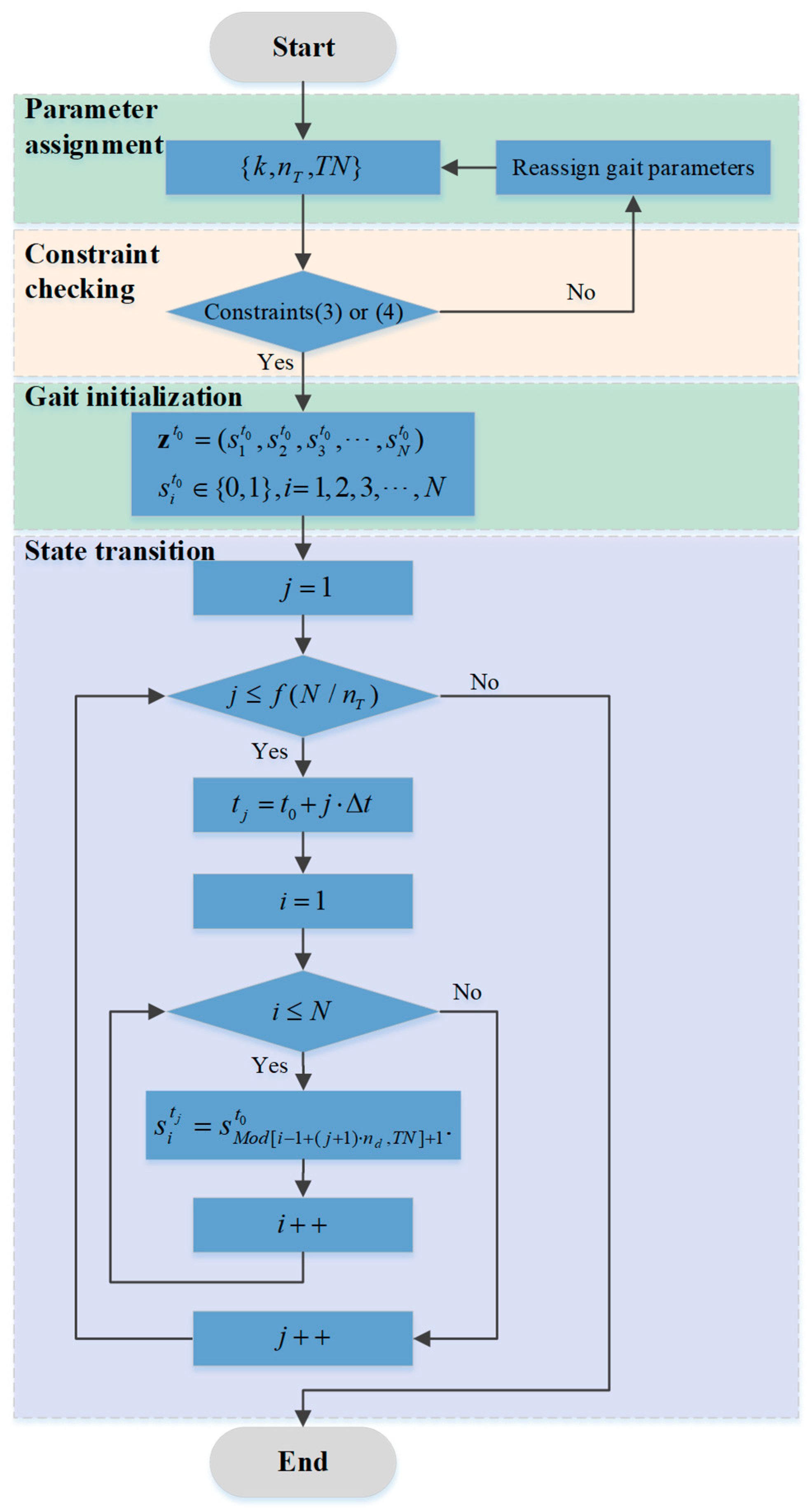
3.1.1. Generation Algorithm for MG-I

In the transmission mode of driven module waves without overlapping, the number of transmission segments n T satisfies
n T = n t d ,   o r   n T = n p
where ntd equals the number of actuated body segments in the U-DM, and np equals the sum of the actuated segments npa and nonactuated segments npu in the B-DM, defined as Equation (4).
The state of the ith segment at the t moment is defined as s i t , in which “0” represents the nonactuated state and “1” represents the actuated state. The states of all the segments can be composed as a state vector at a time point t, denoted by z t . So, for the earthworm-like robot with TN body segments, there is
s i t 0 , 1 , z t = ( s 1 t , s 2 t , s 3 t , , s T N t ) .
The state vector at each time moment can be determined according to the receding peristaltic wave locomotion characteristic of the earthworm. The locomotion gait ( z t 0 , z t 1 , z t 2 , z t n ) can be successively obtained over a period of time. For the transmission of the driven module waves without overlapping, the period of the locomotion can be acquired as
T = μ ( T N / n T ) Δ t
where Δ t is the interval between each state transmission, and μ is a smallest positive integer, rendering the value μ ( T N / n T ) to be an integer. Then, in the locomotion of an earthworm-like robot, the condition for a state switch is given as
s i t j = s M o d [ i 1 + ( j + 1 ) · n T , T N ] + 1 t 0
where Mod[·] expresses the modulo operation. According to the locomotion characteristics of a receding peristaltic wave and the state transmission rule, a gait generation algorithm for the driven module waves without overlapping is developed to generate the locomotion gait. The routine of the algorithm is shown in Figure 5. First, the parameters, { k , n T , T N } , are fixed. Then, the verdict of the constraint conditions for Equation (3) or (4) is confirmed. Next, the initialization gait is given. Finally, the transmission for the segments can be acquired as per Equations (6) and (8) for MG-I. According to the algorithm routine in Figure 5, arbitrary gaits can be generated.

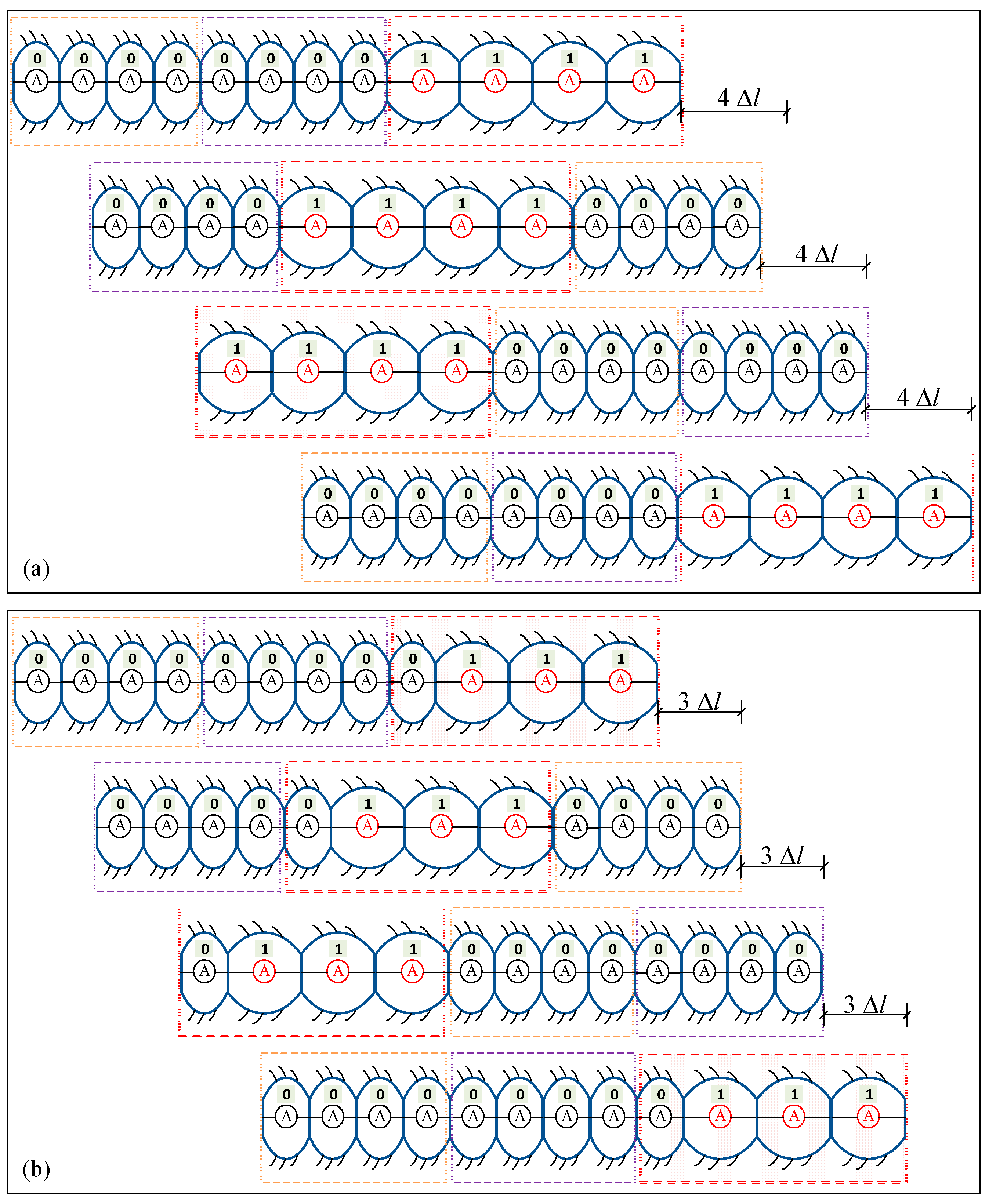
3.1.2. Illustrations for MG-I

This section gives demonstrations for the different driven modules under the MG-I. mode. In the illustration in this case, an earthworm-like robot with 12-body segments, i.e., TN = 12, is selected as an example.
With the proposed gait generation algorithm (proposed in Figure 5) for a 12-segment earthworm-like robot, the gait transmission is shown in Figure 6. Assuming that each driven module consists of four body segments, the driven module passes to the fifth body segment and to the eighth body segment at the second moment, and so on, in a similar fashion. The gait generation demonstrates a 12-segment robot under the U-DM, as shown in Figure 6a. The earthworm-like locomotion robot advances 4   Δ l with each transmission of the U-DM. Figure 6b shows a gait generation demonstration for a 12-segment robot under the B-DM. The body state of the B-DM is indicated as “0111”. With each state transmission of the B-DM, the earthworm-like locomotion robot advances 3   Δ l . It is noticed that the fourth, eighth, and twelfth body segments of the robot are always in the nonactuated state during the whole cycle of the receding peristaltic wave transmission. Although this transmission mode is not the fastest, it is a necessary solution in some specific environments. For example, an earthworm-like locomotion robot has a carrier segment or a segment where the actuator fails.

3.2. Driven Module Waves with Overlapping

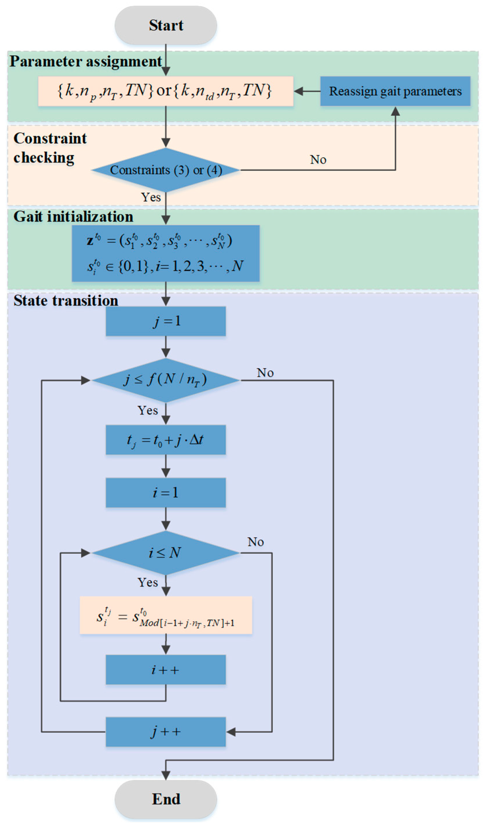
3.2.1. Generation Algorithm for MG-II

As the results in references [17,18] for the peristaltic waves, as the actuated segments transmit from head to tail in the locomotion robot, the optimal gait is obtained, which is called the phase difference gait. For driven module gait generation in this study, the phase difference is considered the modular gait. In this modular gait, the number of transmission segments, n T , is less than the sum of the number of body segments in the driven module (ntd or np). For MG-II, the number of transmission actuated segments, n T , satisfies
1 n T < n t d ,   o r   1 n T < n p
In contrast to MG-I, the parameters for MG-II, { k , n p , n T , T N } or { k , n t d , n T , T N } , are given initially. The state switch in the process of peristaltic waves transmission is defined as
s i t j = s M o d [ i 1 + j · n T , T N ] + 1 t 0
A generation algorithm for MG-II is proposed to obtain the locomotion gait, according to the receding peristaltic wave and the state transmission rule, given as Equation (10). The routine of the algorithm is shown in Figure 7, which can generate all the permissible locomotion gaits.

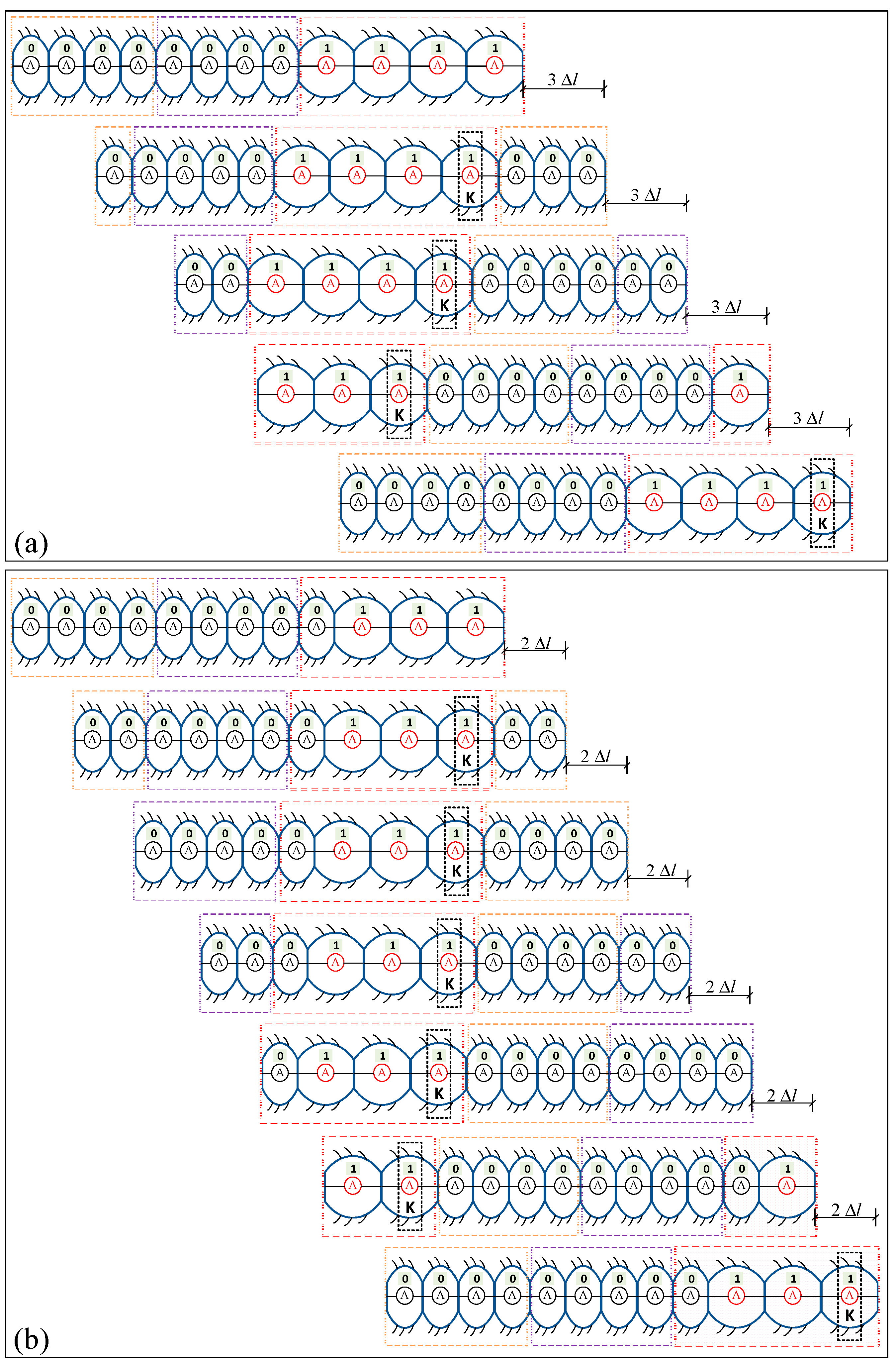
3.2.2. Illustrations for MG-II

With the proposed gait generation algorithm in Figure 7, Figure 8 demonstrates the locomotion gait transmissions of the 12-segment robot with MG-II under two cases: total or partial actuated segments. Figure 8a shows a gait generation demonstration for a 12-segment robot under U-DM, while Figure 8b shows a gait generation demonstration for a 12-segment robot under B-DM. Assuming that each driven module contains four segments, the number of transmission segments is less than the number of segments in one driven module (for the driven mode with MG-II). Then, overlapped segments can occur in the transmission of the driven module. The overlapped segments keep the state of the previous movement, which are called “K” segments, as shown in Figure 8.
Regarding the gait generation in Figure 8a for a 12-segment robot under U-DM with four actuated segments, there is a “K” segment when transmitting the three segments every time. The number of transmission segments is equal to three-quarters of the module phase difference. The number of body segments in the U-DM equals the sum of the number of transmission segments and the number of “K” segments. The earthworm-like locomotion robot advances 3   Δ l with each transmission of the U-DM. In this gait module mode, locomotion speed depends only on the number of transmission segments.
For the B-DM with gait generation, as per Figure 8b, the body state of the B-DM indicates “0111”. The earthworm-like robot advances 2   Δ l with each transmission of the B-DM. The locomotion speed is related to the number of actuated segments and the number of transmission segments. There is only one “K” segment when transmitting two segments in every transmission, as shown in Figure 8b, since there is a nonactuated segment at the tail end of the driven module (looking from right to left). The number of “K” segments is related to the arrangement of the actuated segments and the nonactuated segments in the driven module.

4. Locomotion Simulation

In Section 2 and Section 3, the driven module, the modular gait generation algorithm, and the illustrations for locomotion are given. A simulation of the locomotion of an earthworm-like robot based on a dielectric elastomer actuator is analyzed in this section. It is stated that the earthworm-like locomotion robot can realize crawling locomotion via the combination of anchoring constraint and gait.

4.1. The Locomotion Simulation of an Earthworm-like Robot

In order to simulate the locomotion of the earthworm-like robot, a flow chart of the calculations, which consists of three parts, is shown in Figure 9. It is assumed that each movement of the peristaltic wave adopts complete anchorage without slip. First, the parameters, including the geometric parameters (initial body length l0; the number of body segments TN) and material parameters (the linear spring with stiffness k, spring stiffness ki, the viscous coefficient ci, and the equivalent mass m) are assigned. Then, after the input excitation voltage, the xi is calculated by Equation (1). The minimum and maximum points of xi are stored with LMin[i] and LMax[i], respectively. The body length li (t) of the actuated segment can be calculated by Equation (2). Finally, taking the position of the last body segment, p l a s t , as a reference point, the peristalsis locomotion pi path of the earthworm-like robot is obtained by updating the coordinates of the body segment, according to
p i = p l a s t + m = i T N l T N m + i
According to the routine of the earthworm-like robot locomotion simulation shown in Figure 9, a 12-segment earthworm-like locomotion robot is used for numerical illustration. The results of the modular gait transmission and displacement are shown for the unbroken/broken driven module under driven module waves with/without overlapping. Figure 10 shows the gait generation and locomotion for U-DM with three/four actuated segments under MG-I. For the earthworm-like robot with only one driven module, the number of actuated segments within the driven module determines the frequency and amplitude of the receding peristaltic wave. The characteristics of the wave determine the robot locomotion performance. In Figure 10a, the frequency of the receding peristaltic wave is 1/4, and the amplitude of the receding peristaltic wave is 3. In Figure 10b, the frequency of the receding peristaltic wave is 1/3, and the amplitude of the receding peristaltic wave is 4. Locomotion performance is positively correlated with the amplitude of the receding peristaltic wave. As shown in Figure 10, the earthworm-like robot with the driven module of four actuated segments has better locomotion performance than an earthworm-like robot with three actuated segments as the driven module.
Figure 11 shows the gait generation and locomotion for one U-DM with four actuated segments. The locomotion displacements of the 12-segment robot under MG-II are shown in Figure 11. For the case in Figure 11a, two segments overlap in the driven module. The frequency of the receding peristaltic wave is 1/6, and the amplitude of the receding peristaltic wave is 2. The earthworm-like robot stretches two segments every time it updates, generating a displacement of 2   Δ l . For the case in Figure 11b, when the number of transmission segments is three, it assumes that one segment overlaps. The frequency of the receding peristaltic wave is 1/4, and the amplitude of the receding peristaltic wave is 3. The earthworm-like robot stretches three segments every time it updates, generating a displacement of 3   Δ l . Therefore, the locomotion speed of the earthworm-like robot is positively correlated with the amplitude of the receding peristaltic wave.
Figure 12 shows the locomotion for B-DM under MG-I. For the two cases compared in Figure 12, the driven modules both consist of four segments. In Figure 12a, two segments are assumed to be broken, while in Figure 12b, only one segment is broken. In Figure 12a, the frequency of the receding peristaltic wave is 1/3, and the amplitude of the receding peristaltic wave is 2. In Figure 12b, the frequency of the receding peristaltic wave is 1/3, and the amplitude of the receding peristaltic wave is 3. In the B-DM mode under MG-I, the fewer the broken segments, the greater the amplitude of the receding peristaltic wave, and a faster speed can be obtained. That is, compared to the locomotion speeds between the two cases, this reveals that the more segments that are kept actuated, the faster the movement of the robot.
Figure 13 shows the locomotion for B-DM under MG-II. The B-DM consists of three actuated segments and one nonactuated segment (“1011”). As two segments are transmitted at a time, there are two segments that are overlapping waves, as shown in Figure 13a. The frequency of the receding peristaltic wave is 1/6, and the amplitude of the receding peristaltic wave is 2. When the number of transmission segments is three, there is one segment that is an overlapping wave, as shown in Figure 13b. The frequency of the receding peristaltic wave is 1/4, and the amplitude of the receding peristaltic wave is 2. Therefore, a faster frequency can also obtain greater speed. When more actuated segments are transmitted at a time, the earthworm-like robot can obtain a faster speed.

4.2. Gait Analysis and Discussions

Through the gait generation analysis for kinematics, the average speeds of the earthworm-like locomotion robot in different modes are obtained, as shown in Table 1. Based on the driven characteristics of a dielectric elastomer actuator, the deformations of the dielectric elastomer actuator gradually reach a stable value with an increase in actuator time. Δ l is selected as the baseline to unify a comparison of the average speeds. Δ l is the maximum value of Δ l i j . The average speed of one segment is V ¯ = Δ l / Δ t . This shows that the value of the average speed is dependent on the parameters of the driven modes rather than the number of total body segments TN. Thus, an improvement in locomotion performance can be realized by the optimization of the driven modes.
Table 2 analyzes the upper limit of the average speeds with different locomotion modes when the earthworm-like robot has one driven module. For the driven module with three segments, the maximum locomotion speed is 3 V ¯ . For the driven module with four segments, there are four locomotion modes. When all segments in the driven module are actuated, the average speed is the fastest (up to 4   V ¯ ) under the driven module with MG-I. As the driven module has a broken segment in it, the average speed can reach 3 V ¯ , which is 75% of the maximum locomotion speed of the U-DM. The average speed (3 V ¯ ) is the same as the maximum locomotion speed of the three-segment driven module, and this is better than the average speed of the four-segment driven module with MG-II. According to the analysis, the desired locomotion speed of the earthworm-like robot can be obtained by choosing the appropriate locomotion mode when there are broken or overloaded segments in the earthworm-like robot.
For the same number of body segments, TN, the average speed is positively correlated with the number of driven modules, the number of actuated body segments, and the number of transmission segments. The average speed does not depend on the number of segments of the earthworm-like robot, TN. The optimal phase difference gait control makes the earthworm-like robot obtain an effective average speed in related work [15]. However, with an increase in robot body segments, its weight also increases, resulting in the locomotion speed saturation phenomenon. When compared with the optimal phase-difference gait control of the servo-driven rigid-body robot, the modular gait control shows better performance on the light flexibility robot. There is no saturation phenomenon regarding the average speed with an increase in the number of body segments. When the proportion of the actuated segments is larger, the robot has a greater speed. More importantly, different modular gait control designs can compensate for the lost mobility of the robot due to the inoperable parts of its body segments.
Because the mass of the body segments of the rigid-body earthworm-like robot is large, a large number of body segments leads to a heavy load. Lumping resistance will lead to a decrease in the locomotion efficiency of the earthworm-like robot. For the robots with dielectric elastomer actuators and multiple body segments, it will not be difficult to move forward because of the light weight of the earthworm-like robot. Therefore, this is an important reason for the use of soft, lightweight actuators in earthworm-like locomotion robots.

5. Conclusions

In this paper, driven modules and modular gaits that are realized by using soft actuators due to their low weight and flexibility are proposed. Two driven modules and two locomotion transmission modes are analyzed. For the different driven modules, we give the gait generation algorithms. When compared to rigid-body earthworm-like robots, the soft, earthworm-like robots with a modular driven mode has great advantages in locomotion performance. The soft, earthworm-like robots can locomote under ultra-low frequency excitation with appropriate shifts. Based on the gait analysis and simulation results, the main contributions of this study are summarized as follows:
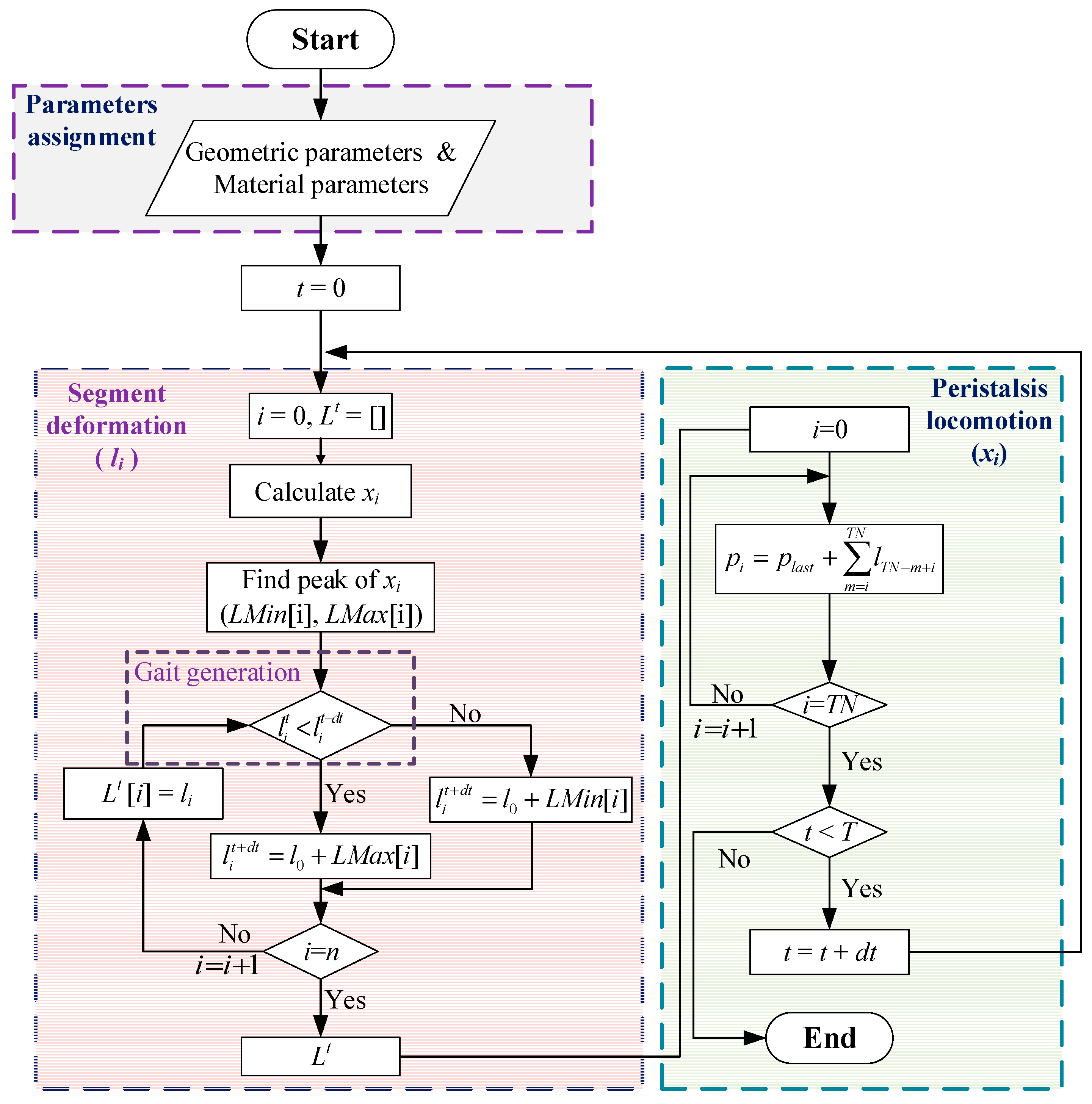
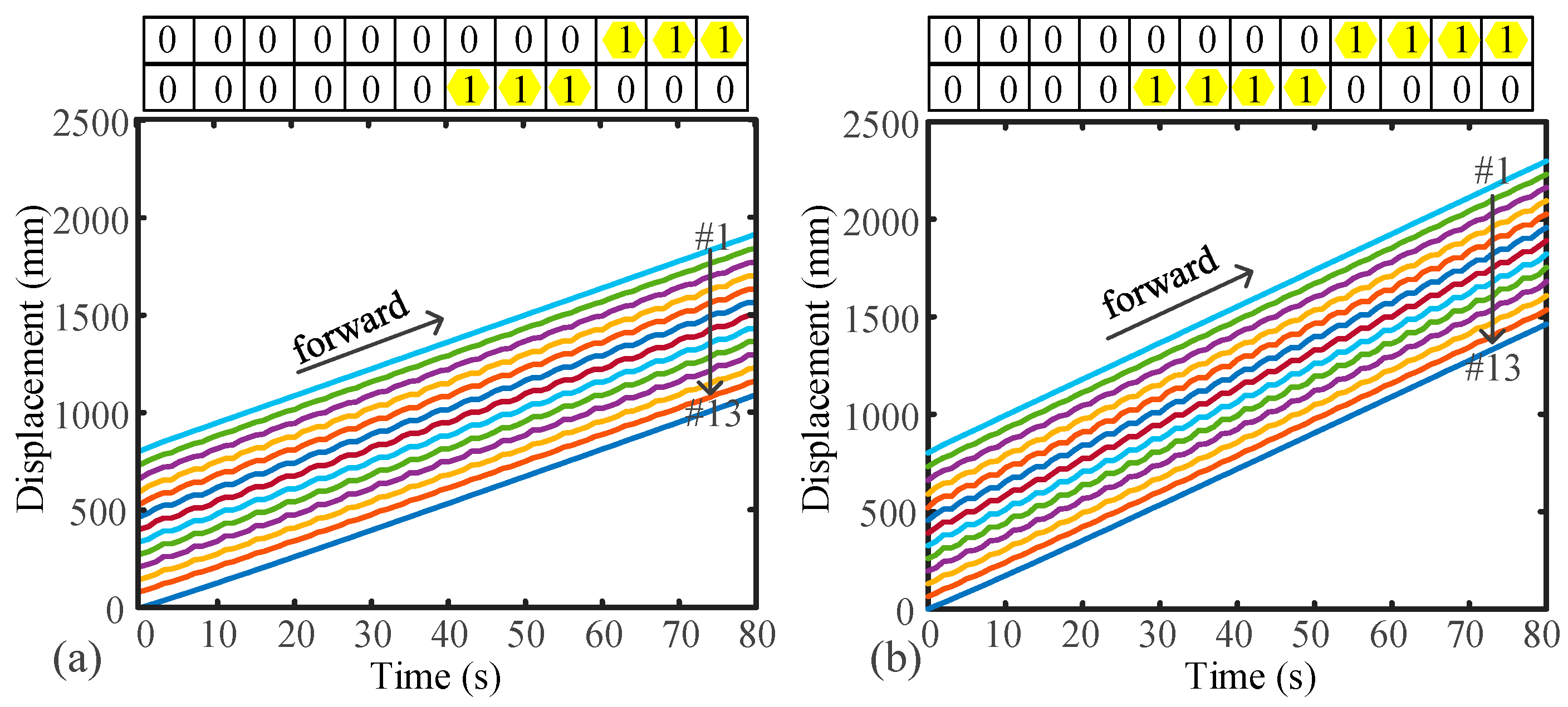
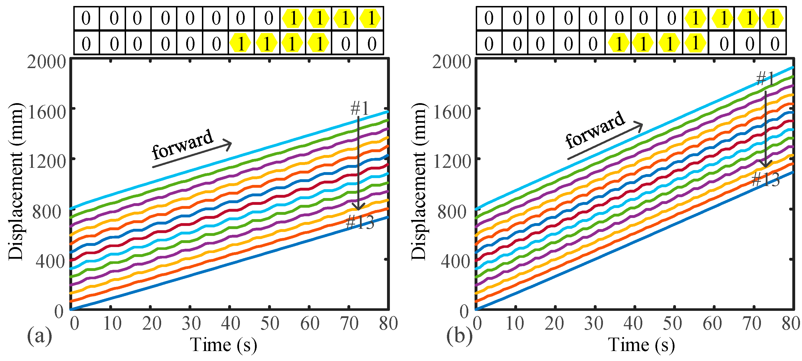
  • A locomotion algorithm is proposed to simulate the locomotion of the soft, earthworm-like robot. The locomotion of a 12-segment earthworm-like robot is numerically simulated based on different modes. The locomotion speed of the earthworm-like robot is positively correlated with the frequency and amplitude of the receding peristaltic wave. The robot can obtain higher speeds when the proportion of the actuated segments increases. For the driven module containing n segments, the maximum speed is k n V ¯ ;
  • The average speeds for different locomotion modes are obtained. For the dielectric-elastomer-driven robot, the proportion of the number of actuated segments strongly affects the average speed. As the proportion of the number of actuated segments increases, the average speed increases;
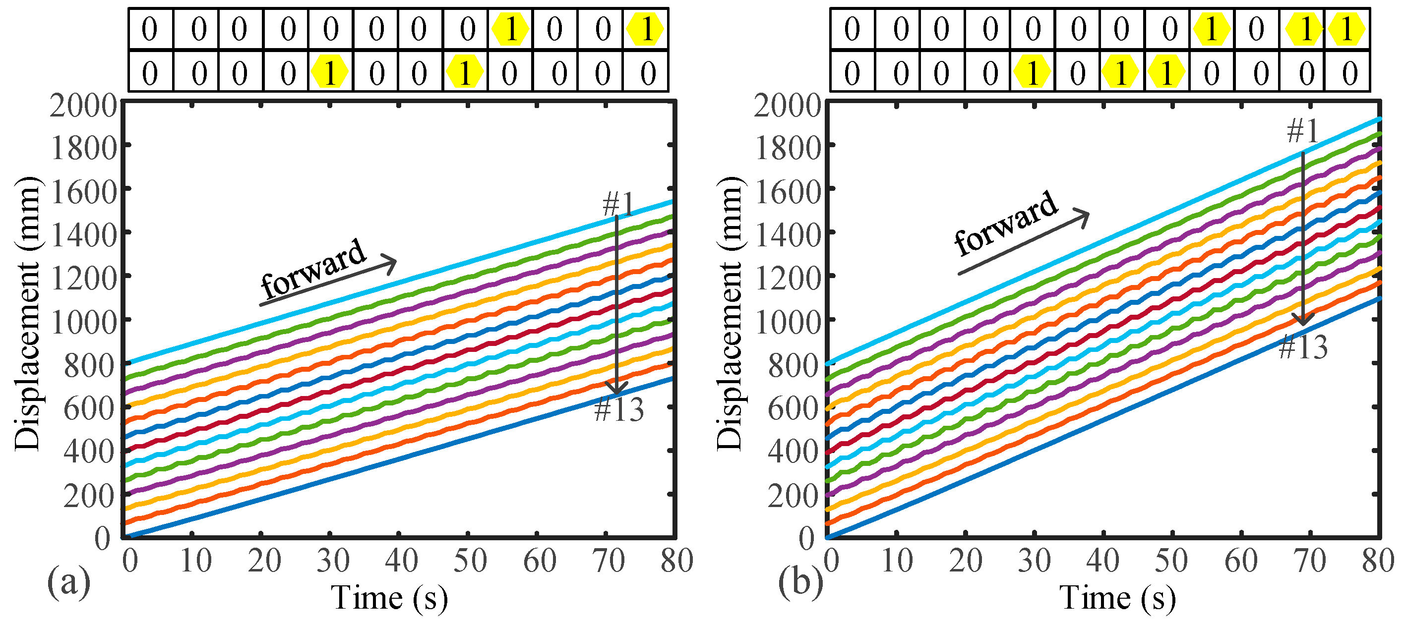
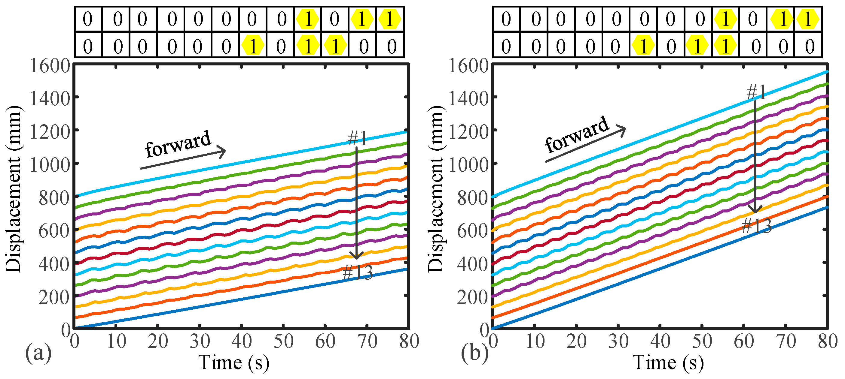
  • When there are failed segments in the robot, a modular gait mode can be designed to improve the locomotion speed of the robot. For the driven module, npa = 3 and npr = 1, there are three different speeds: V ¯ , 2 V ¯ , and 3 V ¯ .
Based on the results of the modular gait generation method and the corresponding average speed, the modular driven mode has excellent locomotion performance. The theoretical analysis and simulation results of this paper provide the necessary theoretical support for the flexibility and low weight of earthworm-like locomotion robots.

Author Contributions

Conceptualization, X.S. and Z.Q.; methodology, Z.Q.; software, Z.Q.; validation, X.S. and Z.Q.; formal analysis, Z.Q.; investigation, Z.Q.; resources, Z.Q.; data curation, Z.Q.; writing—original draft preparation, Z.Q.; writing—review and editing, X.S.; visualization, X.S. and Z.Q.; supervision, X.S.; project administration, X.S.; funding acquisition, X.S. All authors have read and agreed to the published version of the manuscript.

Funding

This research was funded by National Natural Science Foundation of China grant number 12122208, 11972254, and 11932015 and the Fundamental Research Funds for Central Universities.

Institutional Review Board Statement

Not applicable.

Informed Consent Statement

Not applicable.

Data Availability Statement

All data generated or analyzed during this study are included in this published article.

Acknowledgments

The authors would like to thank the reviewers and editors for improving this manuscript.

Conflicts of Interest

The authors declare that they have no conflict of interest.

References

  1. Lin, H.T.; Leisk, G.G.; Trimmer, B. GoQBot: A caterpillar-inspired soft-bodied rolling robot. Bioinspir. Biomim. 2011, 6, 026007. [Google Scholar] [CrossRef] [PubMed]
  2. Li, W.-B.; Zhang, W.-M.; Zou, H.-X.; Peng, Z.-K.; Meng, G. A Fast Rolling Soft Robot Driven by Dielectric Elastomer. IEEE/ASME Trans. Mechatron. 2018, 23, 1630–1640. [Google Scholar] [CrossRef]
  3. Zhong, B.; Zhang, S.; Xu, M.; Zhou, Y.; Fang, T.; Li, W. On a cpg-based hexapod robot: Amphihex-ii with variable stiffness legs. IEEE/ASME Trans. Mechatron. 2018, 23, 542–551. [Google Scholar] [CrossRef] [Green Version]
  4. Chen, S.; Cao, Y.; Sarparast, M.; Yuan, H.; Dong, L.; Tan, X.; Cao, C. Soft Crawling Robots: Design, Actuation, and Locomotion. Adv. Mater. Technol. 2020, 5, 1900837. [Google Scholar] [CrossRef]
  5. Shepherd, R.F.; Ilievski, F.; Choi, W.; Morin, S.A.; Stokes, A.A.; Mazzeo, A.D.; Chen, X.; Wang, M.; Whitesides, G.M. Multigait soft robot. Proc. Natl. Acad. Sci. USA 2011, 108, 20400–20403. [Google Scholar] [CrossRef] [Green Version]
  6. Fang, H.; Wang, C.; Li, S.; Xu, J.; Wang, K.W. Design and experimental gait analysis of a multi-segment in-pipe robot inspired by earthworm’s peristaltic locomotion. In Bioinspiration, Biomimetics, and Bioreplication 2014; SPIE: Bellingham, WA, USA, 2014; Volume 9055. [Google Scholar]
  7. Du, Z.; Fang, H.; Xu, J. Snake-worm: A Bi-modal Locomotion Robot. J. Bionic Eng. 2022, 19, 1272–1287. [Google Scholar] [CrossRef]
  8. Luo, Y.; Zhao, N.; Shen, Y.; Li, P. A Rigid Morphing Mechanism Enabled Earthworm-Like Crawling Robot. ASME J. Mech. Robotics. 2023, 15, 011008. [Google Scholar] [CrossRef]
  9. Zhan, X.; Xu, J.; Fang, H. In-plane gait planning for earthworm-like metameric robots using genetic algorithm. Bioinspir. Biomim. 2020, 15, 056012. [Google Scholar] [CrossRef]
  10. Zhan, X.; Fang, H.; Xu, J.; Wang, K.-W. Planar locomotion of earthworm-like metameric robots. Int. J. Robot. Res. 2019, 38, 1751–1774. [Google Scholar] [CrossRef]
  11. Rafsanjani, A.; Zhang, Y.; Liu, B.; Rubinstein, S.M.; Bertoldi, K. Kirigami skins make a simple soft actuator crawl. Sci. Robot. 2018, 3, eaar7555. [Google Scholar] [CrossRef] [Green Version]
  12. Kandhari, A.; Huang, Y.; Daltorio, K.A.; Chiel, H.J.; Quinn, R.D. Body stiffness in orthogonal directions oppositely affects worm-like robot turning and straight-line locomotion. Bioinspir. Biomim. 2018, 13, 026003. [Google Scholar] [CrossRef] [PubMed]
  13. Kandhari, A.; Mehringer, A.; Chiel, H.J.; Quinn, R.D.; Daltorio, K.A. Design and Actuation of a Fabric-Based Worm-Like Robot. Biomimetics 2019, 4, 13. [Google Scholar] [CrossRef] [PubMed] [Green Version]
  14. Schwebke, S.; Behn, C. Worm-like robotic systems: Generation, analysis and shift of gaits using adaptive control. Artif. Intell. Res. 2012, 1, p12. [Google Scholar] [CrossRef]
  15. Fang, H.; Wang, C.; Li, S.; Wang, K.W.; Xu, J. A comprehensive study on the locomotion characteristics of a metameric earthworm-like robot Part B: Gait analysis and experiments. Multibody Syst. Dyn. 2015, 35, 153–177. [Google Scholar] [CrossRef]
  16. Santhosh, S.; Serra, M. Optimal locomotion for limbless crawlers. Phys. Rev. E 2022, 106, 024610. [Google Scholar] [CrossRef]
  17. Agostinelli, D.; Alouges, F.; DeSimone, A. Peristaltic Waves as Optimal Gaits in Metameric Bio-Inspired Robots. Front. Robot. AI 2018, 5, 99. [Google Scholar] [CrossRef] [Green Version]
  18. Fang, H.; Li, S.; Wang, K.W.; Xu, J. Phase coordination and phase–velocity relationship in metameric robot locomotion. Bioinspir. Biomim. 2015, 10, 066006. [Google Scholar] [CrossRef]
  19. Chapman, G. Of the Movement of Worms. J. Exp. Biol. 1950, 27, 29–39. [Google Scholar] [CrossRef]
  20. Quillin, K.J. Kinematic scaling of locomotion by hydrostatic animals: Ontogeny of peristaltic crawling by the earthworm lumbricus terrestris. J. Exp. Biol. 1999, 202, 661. [Google Scholar] [CrossRef]
  21. Kurth, J.A.; Kier, W.M. Differences in scaling and morphology between lumbricid earthworm ecotypes. J. Exp. Biol. 2015, 218, 2970–2978. [Google Scholar] [CrossRef] [Green Version]
  22. Ilami, M.; Bagheri, H.; Ahmed, R.; Skowronek, E.O.; Marvi, H. Materials, Actuators, and Sensors for Soft Bioinspired Robots. Adv. Mater. 2021, 33, e2003139. [Google Scholar] [CrossRef]
  23. Cianchetti, M.; Laschi, C.; Menciassi, A.; Dario, P. Biomedical applications of soft robotics. Nat. Rev. Mater. 2018, 3, 143–153. [Google Scholar] [CrossRef]
  24. Hines, L.; Petersen, K.H.; Lum, G.Z.; Sitti, M. Soft Actuators for Small-Scale Robotics. Adv. Mater. 2017, 29, 1603483. [Google Scholar] [CrossRef]
  25. Mosadegh, B.; Polygerinos, P.; Keplinger, C.; Wennstedt, S.; Shepherd, R.; Gupta, U.; Shim, J.; Bertoldi, K.; Walsh, C.J.; Whitesides, G.M. Pneumatic Networks for Soft Robotics that Actuate Rapidly. Adv. Funct. Mater. 2014, 24, 2163–2170. [Google Scholar] [CrossRef] [Green Version]
  26. Kim, W.; Seo, B.; Yu, S.Y.; Cho, K.J. Deployable soft pneumatic networks (d-pneunets) actuator with dual-morphing origami chambers for high-compactness. IEEE Robot. Autom. Lett. 2022, 7, 1262–1269. [Google Scholar] [CrossRef]
  27. Guo, Y.; Liu, L.; Liu, Y.; Leng, J. Review of Dielectric Elastomer Actuators and Their Applications in Soft Robots. Adv. Intell. Syst. 2021, 3. [Google Scholar] [CrossRef]
  28. Calderón, A.A.; Ugalde, J.C.; Chang, L.; Zagal, J.C.; Pérez-Arancibia, N.O. An earthworm-inspired soft robot with perceptive artificial skin. Bioinspir. Biomim. 2019, 14, 056012. [Google Scholar] [CrossRef]
  29. Ozkan-Aydin, Y.; Liu, B.; Ferrero, A.C.; Seidel, M.; Hammond, F.L.; Goldman, D.I. Lateral bending and buckling aids biological and robotic earthworm anchoring and locomotion. Bioinspir. Biomim. 2021, 17, 016001. [Google Scholar] [CrossRef] [PubMed]
  30. Ge, J.Z.; Calderon, A.A.; Perez-Arancibia, N.O. An earthworm-inspired soft crawling robot controlled by friction. In Proceedings of the IEEE International Conference on Robotics and Biomimetics (ROBIO), Macau, Macao, 5–8 December 2017; pp. 834–841. [Google Scholar]
  31. Liang, W.; Liu, H.; Wang, K.; Qian, Z.; Ren, L.; Ren, L. Comparative study of robotic artificial actuators and biological muscle. Adv. Mech. Eng. 2020, 12, 2072262428. [Google Scholar] [CrossRef]
  32. Pelrine, R.; Kornbluh, R.; Pei, Q.; Joseph, J. High-Speed Electrically Actuated Elastomers with Strain Greater Than 100%. Science 2000, 287, 836–839. [Google Scholar] [CrossRef] [PubMed]
  33. Gupta, U.; Qin, L.; Wang, Y.; Godaba, H.; Zhu, J. Soft robots based on dielectric elastomer actuators: A review. Smart Mater. Struct. 2019, 28, 103002. [Google Scholar] [CrossRef]
  34. Li, W.B.; Zhang, W.M.; Zou, H.X.; Peng, Z.K.; Meng, G. Multisegment annular dielectric elastomer actuators for soft robots. Smart Mater. Struct. 2018, 27, 115024. [Google Scholar] [CrossRef]
  35. Li, B.; Chen, H.; Qiang, J.; Hu, S.; Zhu, Z.; Wang, Y. Effect of mechanical pre-stretch on the stabilization of dielectric elastomer actuation. J. Phys. D Appl. Phys. 2011, 44. [Google Scholar] [CrossRef] [Green Version]
  36. Zhang, J.; Chen, H.; Li, D. Leakage current and induced electrical energy dissipation in nonlinear oscillation of dielectric elastomer actuators. J. Phys. D Appl. Phys. 2017, 50, 365602. [Google Scholar] [CrossRef]
  37. Jiang, L.; Betts, A.; Kennedy, D.; Jerrams, S. Eliminating electromechanical instability in dielectric elastomers by employing pre-stretch. J. Phys. D Appl. Phys. 2016, 49, 265401. [Google Scholar] [CrossRef]
  38. Choi, H.R.; Ryew, S.; Jung, K.M.; Kim, H.M.; Jeon, J.W.; Nam, J.D.; Maeda, R.; Tanie, K. Microrobot actuated by soft actuators based on dielectric elastomer. In Proceedings of the IEEE/RSJ International Conference on Intelligent Robots & Systems, Lausanne, Switzerland, 30 September–4 October 2002. [Google Scholar]
  39. Pfeil, S.; Henke, M.; Katzer, K.; Zimmermann, M.; Gerlach, G. A Worm-Like Biomimetic Crawling Robot Based on Cylindrical Dielectric Elastomer Actuators. Front. Robot. AI 2020, 7, 9. [Google Scholar] [CrossRef]
  40. Du, Y.; Cao, C.; Wu, X.; Xue, J.; Wang, L.; Gao, X. A low-profile vibration crawling robot driven by a planar dielectric elastomer actuator. In Proceedings of the 2022 IEEE International Conference on Real-time Computing and Robotics (RCAR), Guiyang, China, 17–22 July 2022; pp. 413–418. [Google Scholar]
  41. Mihai, D.; David, R.C.; Robert, J.W. A high speed soft robot based on dielectric elastomer actuators. IEEE Int. Conf. Robot. Autom. (ICRA) 2017, 5, 466–474. [Google Scholar]
  42. Zhao, W.; Zhang, Y.; Wang, N. Soft robotics: Research, challenges, and prospects. J. Robot. Mechatron. 2021, 33, 45–68. [Google Scholar] [CrossRef]
  43. Xu, L.; Chen, H.-Q.; Zou, J.; Dong, W.-T.; Gu, G.-Y.; Zhu, L.-M.; Zhu, X.-Y. Bio-inspired annelid robot: A dielectric elastomer actuated soft robot. Bioinspir. Biomim. 2017, 12, 025003. [Google Scholar] [CrossRef] [Green Version]
  44. Lu, X.; Wang, K.; Hu, T. Development of an annelid-like peristaltic crawling soft robot using dielectric elastomer actuators. Bioinspir. Biomim. 2020, 15, 046012. [Google Scholar] [CrossRef]
  45. Nguyen, V.D.; La, N.T. An improvement of vibration-driven locomotion module for capsule robots. Mech. Based Des. Struct. Mach. 2020, 50, 1658–1672. [Google Scholar] [CrossRef]
  46. Wu, C.; Yan, H.; Cai, A.; Cao, C. A Dielectric Elastomer Actuator-Driven Vibro-Impact Crawling Robot. Micromachines 2022, 13, 1660. [Google Scholar] [CrossRef] [PubMed]
  47. Akbarimajd, A.; Sotoudeh, N. Design and motion analysis of vibration-driven small robot Rizeh. Adv. Robot. 2014, 28, 105–117. [Google Scholar] [CrossRef]
  48. Wang, X.J.; Meng, L.L.; Yao, Y.H.; Li, H.G. A vibration-driven locomotion robot excited by time-varying stiffness. Int. J. Mech. Sci. 2023, 243, 108009. [Google Scholar] [CrossRef]
  49. Diao, B.; Zhang, X.; Fang, H.; Xu, J. Bi-objective optimization for improving the locomotion performance of the vibration-driven robot. Arch. Appl. Mech. 2021, 91, 2073–2088. [Google Scholar] [CrossRef]
  50. Gu, G.-Y.; Gupta, U.; Zhu, J.; Zhu, L.-M.; Zhu, X. Modeling of Viscoelastic Electromechanical Behavior in a Soft Dielectric Elastomer Actuator. IEEE Trans. Robot. 2017, 33, 1263–1271. [Google Scholar] [CrossRef]
Figure 1. A model schematic diagram and the deformation response of a body segment from the earthworm-like robot driven by a dielectric elastomer actuator. (a) A diagram of the body segment deformation. F d r i v e n ( t ) is the ultra-low frequency excitation. Gray represents the initial state of the segment, and blue represents the actuation state of the segment. “A” indicates the actuator; gray indicates the inactive state, and red indicates the active state. (b) A dynamic model of the body segment. (c) The response of the body segment under excitation by sinusoidal excitation voltage. The yellow line represents the simulated body segment length deformation, and the blue line represents the excitation voltage.
Applsci 13 02723 g001
Figure 2. The kinematic state definition of the body segment of the earthworm and the earthworm-like robot. A schematic diagram of the earthworm muscles contracting the segment (a). The initial state of the bionic segment represents “0” in (b). A schematic diagram of the earthworm muscle elongating segment is shown in (c). The final state “1” of the bionic segment with actuation, is shown in (d).
Applsci 13 02723 g002
Figure 3. The initial distribution of the U-DM for a 12-segment earthworm-like locomotion robot. (a) The initial distribution of the U-DM with three actuated segments. (b) The initial distribution of the U-DM with four actuated segments.
Applsci 13 02723 g003
Figure 4. The initial distribution of the B-DM with four segments for a 12-segment earthworm-like locomotion robot. (a) A broken, nonactuated body segment exists in the driven module (“1011”). (b) The nonactuated body segment is located at the boundary of the driven module (“0111”).
Applsci 13 02723 g004
Figure 5. Routine of the generation algorithm for MG-I.
Applsci 13 02723 g005
Figure 6. A gait generation demonstration for a 12-segment earthworm-like robot with two different drive modules for MG-I. A gait generation demonstration for a 12-segment robot with U-DM is shown in (a). The frequency of receding peristaltic wave is 1/3. The amplitude of the receding peristaltic wave is 4. A gait generation demonstration for a 12-segment robot under B-DM (“0111”) is shown in (b). The frequency of receding peristaltic wave is 1/3. The amplitude of the receding peristaltic wave is 3.
Applsci 13 02723 g006
Figure 7. Routine of the generation algorithm for MG-II.
Applsci 13 02723 g007
Figure 8. The gait generation demonstrations for a 12-segment robot with two different driven modules with MG-II. The “K” indicates keeping the previous state segments. A gait generation demonstration for a 12-segment robot under U-DM is shown in (a). The frequency of the receding peristaltic wave is 1/4. The amplitude of the receding peristaltic wave is 3. A gait generation demonstration for a 12-segment robot under B-DM (“0111”) is shown in (b). The frequency of the receding peristaltic wave is 1/6. The amplitude of the receding peristaltic wave is 2.
Applsci 13 02723 g008
Figure 9. Routine of locomotion simulation of the earthworm-like robot driven by ultra-low frequency excitation.
Applsci 13 02723 g009
Figure 10. Locomotion simulations of a 12-segment earthworm-like robot based on U-DM under MG-I. The line located in the number is the locomotion tracks of the body segments. (a) The U-DM contains three actuated segments. (b) The U-DM consists of four actuated segments.
Applsci 13 02723 g010
Figure 11. Locomotion simulations of a 12-segment earthworm-like robot based on U-DM with MG-II. The line located in the number is the locomotion tracks of the body segments. The driven module consists of four actuated segments. (a) The transmission segments contain two segments. (b) The transmission segments contain three segments.
Applsci 13 02723 g011
Figure 12. Locomotion simulations of a 12-segment earthworm-like robot based on B-DM with MG-I. The line located in the number is the locomotion tracks of the body segments. (a) The B-DM for four body segments has two actuated segments (“1001”). (b) The B-DM for four body segments has three actuated segments (“1011”).
Applsci 13 02723 g012
Figure 13. Locomotion simulations of a 12-segment earthworm-like robot based on B-DM with MG-II. The line located in the number is the locomotion tracks of body segments. Three actuated segments in the B-DM of four body segments (“1011”). (a) The transmission segments consist of two segments. (b) The transmission segments consist of three segments.
Applsci 13 02723 g013
Table 1. The average speeds of the different locomotion modes of the earthworm-like robot.
ModesConstraint ConditionsThe Average Speeds
The U-DM with MG-I k 1 , n t d 1 , T N ( k + 1 ) n t d ; n T = n t d . V = 1 Δ t j = 1 k i = 1 n t d Δ l i j k n t d V ¯ .
The U-DM with MG-II k 1 , n t d 1 , T N ( k + 1 ) n t d ; 1 n T < n t d . V = 1 Δ t j = 1 k i = 1 n T Δ l i j k n T V ¯ .
The B-DM with MG-I k 1 , n p a 1 , n p r 1 , n p = n p a + n p r , T N k n p ; n T = n p . V = 1 Δ t j = 1 k i = 1 n p a Δ l i j k n p a V ¯ .
The B-DM with MG-II k 1 , n p a 1 , n p r 1 , n p = n p a + n p r , T N k n p ; 1 n T < n p . V = 1 Δ t j = 1 k i = 1 n T Δ l i j k n T V ¯ ,   ( i f : 1 n T < n p a ) ; V = 1 Δ t j = 1 k i = 1 n p a Δ l i j k n p a V ¯ ,   ( i f : n p a n T < n p ) .
Table 2. The average speeds when k = 1.
The Number of Body Segments in a Driven Module (n)Driven ModulesWave Transmission ModesAverage Speeds
n=3U-DMMG-I V = 3   V ¯ .
MG-II n T = 1 : V 1 = V ¯ ; n T = 2 : V 2 = 2   V ¯ .
n=4U-DMMG-I V = 4   V ¯ .
MG-II n T = 1 : V 1 = V ¯ ; n T = 2 : V 2 = 2   V ¯ ; n T = 3 : V 3 = 3   V ¯ .
B-DM
(npa = 3, npr = 1)
MG-I V = 3   V ¯ .
MG-II n T = 1 : V 1 = V ¯ ; n T = 2 : V 2 = 2   V ¯ ; n T = 3 : V 3 = 3   V ¯ .
Disclaimer/Publisher’s Note: The statements, opinions and data contained in all publications are solely those of the individual author(s) and contributor(s) and not of MDPI and/or the editor(s). MDPI and/or the editor(s) disclaim responsibility for any injury to people or property resulting from any ideas, methods, instructions or products referred to in the content.

