1. Introduction
As the observation resolution of space payloads continues to increase, high stability and pointing accuracy of satellite platforms are required simultaneously. For example, the collaborative development of the “Solar-B” satellite involved Japan, the United States, and the United Kingdom in 2006, with a short-period pointing stability of 0.09 arcseconds (3 σ)/10 s [
1,
2]. Similarly, the United States developed the “Space Interferometry Mission” space telescope, which had a pointing stability of 1.6 mas (1 σ)/0.01 s [
3]. Flywheels serve as commonly used attitude control actuators in spacecraft [
4,
5,
6]. Nevertheless, due to the high angular velocity at which flywheels typically operate (1000~8000 rpm), various factors like rotor static and dynamic imbalance, non-ideal bearings, drive motor disturbances, and resonance in flexible structures can generate sustained vibrations characterized by harmonic and wide frequency bands. Park et al. reported that the disturbances consist of discrete harmonics of the wheel speed with amplitudes proportional to the square of the wheel speed. Some disturbances include interactions between the harmonics and the structural modes of the wheel which result in large disturbance amplifications at some wheel speeds [
7]. These vibrations constitute the primary source of interference that significantly impacts the design performance of payloads [
8,
9,
10,
11]. In particular, for optical payloads, the impact of flywheel disturbance cannot be ignored and is difficult to eliminate.
For satellites that require high attitude stability and accuracy, the suppression of flywheel vibration is crucial. Since the disturbance of the flywheel system is generally multi-directional, most isolation devices for flywheels employ multiple independent isolation rod units. They form a multi-degree-of-freedom isolation platform with a certain topology configuration to suspend and isolate the flywheel system. This isolation method has greater flexibility, better omnidirectional isolation performance, and higher reliability. For example, China’s FY-4 satellite [
12] utilized a 6-DOF (six-degree-of-freedom) passive isolation platform to isolate the flywheel’s vibration. The GOES-R satellite launched by the United States in 2016 applied viscoelastic isolators to reduce the impact of the disturbance from its six flywheels and achieved significant attenuation of vibration above 50 Hz [
13]. A double-layer passive isolation system based on viscoelastic material is used in China’s Gaofen-3 optical satellite for flywheel disturbance suppression [
5]. D. Kamesh from India [
14,
15] proposed a flexible isolation platform based on a folding beam structure, which can reduce the installation stiffness of the flywheel and effectively suppress the vibration disturbance. The WorldView-I and WorldView-II Earth observation satellites [
16] launched by DigitalGlobe integrated eight isolation rod units with the CMG group. Lin et al. [
17] studied the influence of flywheel vibration on optical cameras. Results showed that a flywheel isolation platform with four metal rubber isolation components can reduce the optical axis angular displacement of the optical payload by over 50%. Wei et al. [
18] proposed a passive isolation platform composed of multiple folding beams and established an equivalent kinetic model of the flywheel and platform system. The model was validated through eigenvalue and frequency response analysis, demonstrating that it can effectively reduce the disturbance of the flywheel.
Passive isolation devices reduce micro-vibration by lowering the system frequency and increasing structural damping, and their reliability has led to widespread use in engineering. However, recent research has focused on semi-active and active isolation platforms based on passive ones. For example, Oh et al. [
19,
20,
21] from JAXA developed a variable damping isolation device to reduce the radial disturbance force caused by rotor static unbalance. Zhao et al. [
22] invented an active–passive integrated 3-DOF isolation platform capable of two translational degrees of freedom in the installation plane and one perpendicular to it. Kim et al. [
23,
24] created an active 3-DOF isolation micro-platform using fully active piezoelectric actuators designed with the lever principle. Lee et al. [
7,
25,
26] proposed a hybrid isolation platform with a positive Stewart configuration, utilizing voice coil motors and viscous dampers for support legs to suppress flywheel vibration. Wu et al. [
27] studied the dynamic parameters of the satellite active isolation platform based on genetic and differential evolution algorithms considering load and structural weight. Zhang et al. [
28,
29] created the kinetic model for the satellite with a 6-DOF vibration isolation system. An adaptive controller was designed to handle the uncertainty of the payload’s inertia, and the impact of the vibration isolation system on the satellite’s attitude and stability was evaluated. They further proposed a 6-DOF isolation platform based on magnetic levitation actuators and investigated the electromagnetic coupling effect of the magnetic platform. They numerically verified the effectiveness of the platform for vibration isolation of the payload. It is also reported that the Stewart platforms have achieved active vibration isolation on the Worldview-II and Chandra X-ray observers [
30]. Active isolation platforms typically have controllers and actuators, making them more complex than passive ones. As a result, they are typically only used to isolate effective payloads [
31,
32]. For instance, the Tacsat2 satellite launched by the United States in 2006 featured an active and passive combined isolation device installed on its camera [
33]. On the other hand, passive isolation platforms are typically employed for flywheel vibration isolation [
18].
In the aforementioned research on flywheel vibration isolation, researchers committed to improving the vibration isolation efficiency of the vibration isolation platform itself. However, their investigations have been limited to the premise that the flywheel platform is mounted on a rigid foundation. In practical engineering applications, the flywheels and isolation platforms are typically installed on an elastic foundation, such as a honeycomb structural plate with limited stiffness in the case of satellite structures. Unfortunately, there is a lack of research on whether a flywheel vibration isolation platform designed with a rigid foundation can achieve an equivalent isolation effect when installed on a flexible foundation. Therefore, in this study, the structural plate and the flywheel vibration isolation platform are treated as a plate-isolator system, and the influence of the structural plate’s elasticity is investigated. It is reported that linear boundary damping can reduce the vibration energy of stiffened plates in the specific frequency band [
34]. Thus, in this study, to further suppress the disturbance of flywheels, an elastic boundary is designed for the plate-isolator system, and the plate-isolator system with an elastic boundary is verified by a simplified analytical model and numerical simulation. The rest of this paper is organized as follows:
Section 2 presents a finite element simulation that demonstrates that the high-frequency vibration isolation performance of the flywheel vibration isolation platform can be affected by the elasticity of its mounting surface. In
Section 3, a simplified 2-DOF theoretical model is analyzed to examine the influence of the structural plate stiffness on the overall isolation efficiency of the plate-isolator system. In
Section 4, a simplified 3-DOF model is used to verify that applying an elastic boundary to the structural plate can effectively improve the overall isolation efficiency of the plate-isolator system, and the stiffness of the elastic boundary is optimized.
Section 5 verifies the theoretical optimization results through finite element simulation, which shows that the overall isolation efficiency of the plate-isolator system will be significantly improved due to the plate’s elastic boundary. Finally, in
Section 6, the research conclusions are further verified using a cubic satellite structure, and the finite element simulation results show that setting an elastic interface between the plates on which the flywheels are installed and other plates can significantly reduce the vibration response at various positions of the cubic satellite.
2. Problem Illustration
Flywheels are widely utilized in satellites as the attitude controlling device, and the high-frequency vibration of flywheels usually poses significant challenges in achieving stable mounting interfaces for high-precision payloads.
Figure 1 illustrates a typical three-axis stabilized satellite with a high-precision optical payload. To attenuate the flywheel-induced vibration, the flywheels are installed on 6-DOF vibration isolation platforms. A 6-DOF vibration isolation platform can be designed to exhibit quite low vibration transmissibility. Thus, theoretically, a well-designed vibration isolator should solve the issue of vibration on a satellite very well. For instance, the 6-DOF vibration isolation platform presented in
Figure 1 applies six linear springs with a stiffness
Kspring = 50,000 N/m and the equivalent damping
Cspring = 100 Nm/s. The overall mass of the platform is less than 2 kg, the fundamental frequency of which is about 14 Hz. However, in practice, the isolation platforms are installed on the elastic structural plate of the satellite, which possesses limited stiffness. The elastic structural plate and the isolation platform form an elastic system (plate-isolator system) in essence. Therefore, to effectively suppress the influence of flywheel vibrations, this study will demonstrate that the key is the dynamics of this plate-isolator system rather than merely the dynamics of the isolation platform.
To illustrate the influence of the elastic structural plate on the isolation of flywheel vibrations, the dynamics of a plate-isolator (structural plate and isolation platform) system are analyzed.
Figure 2 illustrates the plate-isolator system and its finite element model. The flywheel has a mass of 8 kg, while the structural plate is a honeycomb sandwich structure with dimensions of 1500 mm × 1500 mm × 30 mm. It consists of a carbon fiber skin and an aluminum honeycomb core.
Table 1 lists the layering and material properties of the structural plate. The dynamic response of the plate-isolator system is evaluated using the commercial finite element software ABAQUS 6.14. Shell elements (S4R) are employed to model both the flywheel and the structural plate. In addition, the vibration isolation platform is modeled using both spring and dashpot elements, as well as shell elements (S4R). The stiffness and damping coefficient of the spring and damping elements are
K = 50,000 N/m and
C = 100 Nm/s, respectively. The shell element size of the structural plate is 25 mm; it is 5 mm for the platform.
To analyze the force transmissibility of the vibration isolation platform itself and the plate-isolator system, frequency response analyses are conducted using the “Steady-state Dynamics, Direct” analysis step in ABAQUS. Sinusoidal excitations are applied in the X, Y, and Z directions at the mass center of the flywheel. For the isolation platform, fixed constraints are applied to its bottom, and the force transmissibility is calculated by extracting the total reaction force at the bottom of the platform. For the plate-isolator system, fixed constraints are applied to the four edges of the structural plate, and force transmissibility is calculated by extracting the total reaction force from the four edges of the structural plate.
Figure 3 compares the force transmissibility curves of the isolation platform and the plate-isolator system in the frequency range of 0~200 Hz, in which obvious differences can be observed. Note that the force transmissibility is defined as 20 × Log (
Freaction/
Finput). The force transmissibility of the plate-isolator system, especially in the Y direction, is considerably worse compared to that of the vibration isolation platform. While the force transmissibility curves of the vibration isolation platform exhibit only one peak in the X, Y, and Z directions, the force transmissibility curves of the plate-isolator system show multiple peaks. Based on the mode analysis results presented in
Figure 3, it is evident that the extra peaks are the results of the local modes of the elastic structural plate. The results in
Figure 3 suggest that to suppress the influence of flywheel vibration on the satellite, a systematic design is needed, considering both the vibration isolation platform and the structural plate as a multi-stage vibration isolation system.
3. Illustration of a Plate-Isolator System as a 2-Stage Vibration Isolation System
To gain insight into the basic dynamic characteristics of the plate-isolator system, the plate-isolator system is simplified into a 2-stage isolation system, as illustrated in
Figure 4. In the simplified 2-stage isolation system, the structural plate is represented as a linear spring with a mass node on its upper end. The node mass
mplate equals the first-order modal mass of the plate. The spring stiffness
Kplate is calculated according to the fundamental modal frequency and the corresponding modal mass of the plate. The vibration isolation platform is also represented as a linear spring, and the flywheel is modeled as a mass node. The spring stiffness
Kisolator is calculated according to the fundamental modal frequency of the vibration isolation platform and the mass of the flywheel. The coefficients
Cplate and
Cisolator denote the equivalent damping coefficient of the structural plate and the vibration isolation platform.
Assuming a harmonic excitation
is applied on the flywheel, the kinetic equations of the 2-stage system can be derived:
where
,
,
,
,
,
, and
x1(
t) and
x2(
t) denote the displacement of mass nodes
mplate and
mflywheel, respectively. Note that these stiffness and damping parameters are different for the vertical and horizontal directions. Respectively assume:
Substituting Equations (2) and (3) into Equation (1), we can derive the following:
By equaling the coefficients of
and
of the two kinetic equations in Equation (4) to 0 respectively, four linear equations of
A1,
A2,
B1, and
B2 can be obtained. By solving the linear equations, the vibration amplitudes
and
take the form:
Based on the amplitude value
, the resultant disturbance force at the edges of the structural plate (namely the reaction force at the fixed end of the plate spring in
Figure 4) can be expressed as:
3.1. Vertical (Y Direction)
When the flywheel vibrates vertically, as illustrated in
Figure 4, the fundamental frequency of the edge fixed structural plate (1000 mm × 1000 mm × 30 mm, the total mass is 50 kg) is calculated to be
via FEA. The corresponding fundamental modal mass is 31.7 kg. In the 2-stage system, the equivalent mass of the plate equals the fundamental modal mass of the plate, i.e.,
. The equivalent stiffness of the plate is
and is calculated based on the fundamental frequency and modal mass. The mass of the flywheel is 8 kg and the fundamental frequency of the vibration isolation platform is
; thus, the equivalent stiffness of the vibration isolation platform is
.
Based on the disturbance force expression of Equation (7), the force transmissibility of the simplified 2-stage vibration isolation system under harmonic excitation is studied (
Figure 5 and
Figure 6). The response curves exhibit two peaks: the first peak corresponds to the isolator mode, while the second peak corresponds to the structural plate mode. The analytical solutions indicate that the increased stage (i.e., the structural plate) introduces an additional peak on each frequency response curve, resulting in a higher isolation starting frequency. To optimize a vibration isolation system, it is common to optimize the damping and stiffness of the system. However, the parameter analysis results presented in
Figure 5 and
Figure 6 demonstrate that optimizing the damping or stiffness is ineffective for this two-stage plate-isolator system.
The effects of plate damping
Cplate and isolator damping
Cisolator on the force transmissibility are shown in
Figure 5.
Figure 5a demonstrates that a large damping coefficient of
Cplate = 10,000 Ns/m is required to effectively suppress the second peak caused by the plate elasticity. If the damping of the structural plate is further increased, the response of the system approaches that of the vibration isolation platform itself. Similarly,
Figure 5b illustrates that increasing the damping of the vibration isolation platform (
Cisolator = 10,000 Ns/m) effectively reduces the peak value of the system response. If the damping of the vibration isolation platform is further increased, the overall response of the system approaches that of the structural plate itself. Therefore, the results in
Figure 5 indicate that the force transmissibility of the plate-isolator system cannot be significantly improved by increasing the damping of the structural plate or the vibration isolator. Infinitely increasing the structural plate damping can eliminate the influence of the structural plate elasticity and ensure the vibration isolation effect of the isolator. However, infinite or quite large damping is usually difficult to achieve in practice for a structural plate.
The influences of the vibration isolator stiffness
Kisolator and the structural plate stiffness
Kplate are presented in
Figure 6. The analysis results in
Figure 6a indicate reducing the isolator stiffness
Kisolator has little effect on the second peak and high-frequency response. Therefore, optimizing the stiffness of the vibration isolator alone cannot significantly improve the vibration isolation effect of the plate-isolator system. On the other hand,
Figure 6b suggests that by reducing the stiffness of the structural plate, the frequency corresponding to the second peak of the force transmissibility shifts forward. Meanwhile, the force transmissibility at high frequency decreases. When the stiffness of the structural plate is reduced to 1/10 of the original value, the force transmissibility of the plate-isolator system exhibits one obvious peak. The overall response is similar to that of a soft 1-DOF vibration isolation system. Compared to optimizing the damping, reducing the stiffness of the structural plate proves to be a more effective method for improving the vibration isolation efficiency of the plate-isolator system. Nevertheless, since the structural plate serves as the mounting surface of various equipment and functions as a load-bearing structure, reducing its stiffness could lead to risks of strength issues and excessive elastic deformation. Moreover, as shown in
Figure 6b, reducing the stiffness of the structural plate may also result in a large peak response, thereby increasing the risk of excessive dynamic response.
To ensure the vibration isolation effect of the plate-isolator system and the reliability of the structure, the next section will adopt the structural plate with elastic boundary conditions to achieve high vibration isolation efficiency.
3.2. Horizontal (X and Z)
For the excitation of the flywheel in the
and
directions, the flywheel and structural plate can also be simplified into a 2-stage system ignoring the higher-order mode of the structural plate, as shown in
Figure 4. The analytical solution of the force transmissibility is the same as Equation (7). However, due to the much higher in-plane stiffness of the structural plate compared with the out-of-plane stiffness, the response of the plate-isolator system in the X and Y directions within the frequency range of 0–100 Hz is similar to that of the isolator fixed at its bottom. It can be predicted from
Figure 6b that reducing the in-plane stiffness of the structural plate to a relatively low value could improve the overall vibration isolation efficiency of the 2-stage system. However, achieving low in-plane stiffness for a honeycomb structural plate through mechanical optimization is difficult. Therefore, the next section will discuss how to enhance the lateral vibration isolation efficiency of the plate-isolator system by adopting the lateral elastic boundary on the structural plate.
4. Illustration of a Plate-Isolator System with Elastic Boundary as a 3-Stage Vibration Isolation System
Section 2 presents the findings of the simplified 2-stage model, which indicate that improving the performance of the plate-isolator system is challenging without reducing the stiffness of the structural plate to a relatively low value. Instead of optimizing the mechanical design of the structural plate, this section explores an alternative method of applying an elastic plate boundary.
Figure 7 shows the plate-isolator system with the elastic boundary. The rigid constraint boundary of the structural plate is replaced with a spring constraint boundary, thereby simplifying the system into an elastic 3-stage system. The first stage is the elastic boundary of the structural plate, the second stage is the structural plate, and the third stage is the vibration isolation platform.
The kinetic equations of the 3-stage system are derived:
where
K1 =
Kplate,
M1 =
mplate-central,
C1 =
Cplate,
K2 = K
isolator,
M2 =
mflywheel,
C2 =
Cisolator,
K3 =
Kboundary,
M3 =
mplate-boundary,
C3 =
Cboundary, and
x1(
t),
x2(
t) and
x3(
t) denote the displacement of mass node
mplate-central,
mflywheel and
mplate-boundary, respectively. To derive the force transmissibility of the 3-stage system, similar to Equations (2) and (3), assume that the displacement response of the structural plate boundary is:
Substitute Equations (2), (3) and (9) into Equation (8), and equal the coefficients of
and
to 0 respectively. Finally, the kinetic equations of
A1,
A2,
B1,
B2,
G1 and
G2 can be obtained:
By solving the equation above, the amplitude
of the elastic boundary response of the structural plate can be obtained, as shown in the
Appendix A. Based on the amplitude value
, the output force of the 3-stage system can be expressed as:
4.1. Vertical (Y Direction)
When the flywheel vibrates vertically, as illustrated in
Figure 7,
mplate-central = 31.7 kg, which equals the fundamental model mass of the boundary fixed plate. As the total mass of the structural plate is 50 kg, then
mplate-boundary = (50−31.7) kg = 18.3 kg.
Kplate = 3,378,239 N/m and is calculated according to the fundamental frequency and the modal mass of the boundary fixed structural plate. The
mflywheel = 8 kg and
Kisolator = 56,321 N/m.
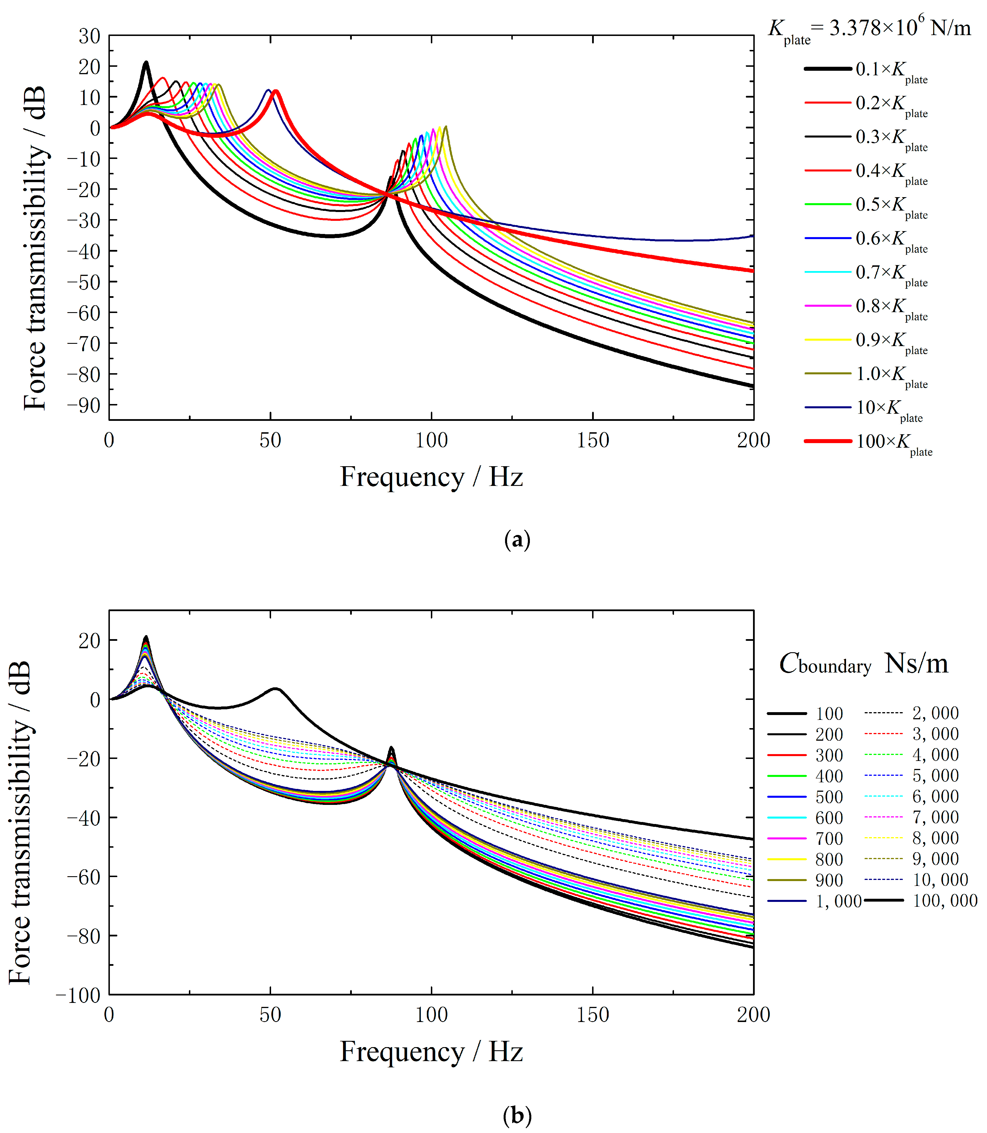
In this section, the influence of the stiffness and damping of the elastic boundary on the force transmissibility of the system is analyzed using the equation presented above. The results are presented in
Figure 8. A sinusoidal force
F·Sin(t) is applied vertically on the node flywheel, and the output force disturbance amplitude of the plate-isolator system is calculated via Equation (11). The force transmissibility is calculated by comparing Equation (11) with the excitation amplitude
F.
Figure 8a illustrates the influence of the boundary stiffness on the force transmissibility of the plate-isolator system. As the system possesses three degrees of freedom, the force transmissibility curve exhibits three distinct peaks. When the boundary stiffness of the structural plate is reduced to 0.1 times that of the structural plate, the first two peaks of the force transmissibility curve overlap. As a result, the force transmissibility curve only has two obvious peaks. If the boundary stiffness is much larger than the structural plate stiffness, the frequency corresponding to the third peak will be greater than 200 Hz, and the response of the system in the frequency range of 0–200 Hz is similar to that of the 2-stage system in
Section 3. Generally, smaller boundary stiffness leads to smaller force transmissibility. Therefore, the structural plate boundary stiffness is initially selected as
Kboundry = 0.1
Kplate for further study.
Figure 8b illustrates the influence of structural plate boundary damping
Cboundary on the system response. When
Cboundary = 10
5 Ns/m, the force transmissibility of the system is similar to the scenario when the boundary of the structural plate is rigidly constrained. When
Cboundary = 100 Ns/m, the force transmissibility curve of the system exhibits two relatively high peaks. However, when
Cboundary is increased to 1000 Ns/m–10,000 Ns/m, the force transmissibility of the system is improved compared to the 2-stage plate-isolator system.
Based on the analysis results presented in
Figure 8, the boundary stiffness of the structural plate is set to
Kboundry = 0.1
Kplate = 337,800 N/m and the boundary damping coefficient is set to
Cboundary = 2000 Ns/m. These settings enable the system to have a wider range of vibration isolation frequency and lower force transmissibility.
4.2. Horizontal (X and Z)
For the horizontal (X and Z) directions, the stiffness
Kplate can be considered to be infinitely large. As a result, the node mass
mplate-central = 0, and
mplate-boundary = 50 kg. The finite element analysis results indicate that the fundamental frequencies of the flywheel vibration isolation platform in the X and Z directions are 13.354 Hz and 21.976 Hz, respectively. The mass of the flywheel is 8 kg and the equivalent stiffness of the isolator in the X and Z directions are
Kisolator-x = 56,321 N/m and
Kisolator-z =152,527 N/m. The influence of the lateral boundary stiffness of the structural plate on the force transmissibility of the plate-isolator is investigated using Equation (11), with the prediction results presented in
Figure 9. When the lateral boundary stiffness of the structural plate is relatively small (specifically below 500,000 N/m in the X direction and 1,000,000 N/m in the Z direction), the force transmissibility of the system has only one peak in 0–100 Hz. If the lateral boundary stiffness of the structural plate increases, the second peak will occur. The peak moves towards a higher frequency as the lateral boundary stiffness increases. Generally, the addition of a lateral elastic boundary to the structural plate can significantly enhance the vibration isolation efficiency of the system, particularly at higher frequencies. Lower lateral boundary stiffness values yield better overall vibration isolation efficiency. In the X and Z directions, if
Kboundary-x = 563,210 N/m and
Kboundary-z = 610,108 N/m, the force transmissibility curves of the plate-isolator system exhibit a single peak at 13.5 Hz, which is in proximity to the fundamental frequency of the vibration isolation platform (13.354 Hz). For simplicity, a lateral boundary stiffness of
Kboundary = 600,000 N/m is used for the structural plate in both X and Z directions in this study.
The effect of lateral boundary damping on the force transmissibility of the plate-isolator system is analyzed in
Figure 10. The results show that a large value of the lateral boundary damping leads to lower peak of the system response. However, to ensure the vibration isolation effect at high frequencies, a compromise value of lateral boundary damping coefficient
Cboundary = 2000 Ns/m is selected.
Based on the simplified 3-stage plate-isolator system, a group of boundary stiffness and damping coefficients are selected. In the vertical direction (Y), Kboundary = 340,000 N/m, Cboundary = 2000 Ns/m. In the horizontal direction (X and Z), Kboundary = 600,000 N/m, Cboundary = 2000 Ns/m. In the next section, finite element simulation will be used to further verify the influence of elastic plate boundaries on the kinetic response of the structural plate.
5. A Plate with Elastic Boundaries and its Dynamic Responses
In this section, the conclusion of the simplified 3-stage model is verified via the multi-DOF finite element model.
Figure 11 shows the finite element model of the plate-isolator with the elastic boundary. The modeling methods of the flywheel, 6-DOF vibration isolator, and structural plate are the same as mentioned in
Section 2. In the finite element model, the X\Y\Z translation freedoms of the four edges of the structural plate are released. The four edges of the structural plate are connected to the ground with 60 vertical spring–dashpot elements and 64 transverse spring–dashpot elements, respectively. Moreover, in practice, the rotational freedoms of the edges are released due to the challenges of applying rotational constraints on the edges of elastically supported structural plates.
In the finite element model, each vertical boundary spring stiffness is set to
, and each vertical damping coefficient is set to
. In the transverse direction, the spring stiffness and the damping coefficient are
and
at each supporting point. Harmonic excitations are applied on the mass center of the flywheel. The predicted force transmissibility of the plate-isolator system with elastic boundaries is shown in
Figure 12. In
Figure 12a, FEA results of the plate-isolator system with elastic boundaries are compared with the 3-stage simplified model. The results of the lumped parameter theoretical model are qualitatively similar to the FEA results. In the vertical direction (y), the results of the multi-DOF finite element model and the lumped parameter theoretical model are a little different after 50 Hz; the main reason is that the lumped parameter theoretical model is not precise enough to illustrate the complicated mode shape of the structural plate. Nevertheless, in this study, the 3-stage simplified lumped parameter model is applied as a guide to choosing the appropriate stiffness and damping for the plate boundary. In
Figure 12b, the force transmissibilities of the plate-isolator system with and without elastic boundary are compared. The predictions show that the vibration isolation effect of the plate-isolator system is obviously improved by the elastic plate boundary. In
Figure 12b, it is demonstrated that the 3-stage simplified model is an effective tool to determine the boundary stiffness and damping for the plate-isolator system.
6. A Cube Satellite with Elastic Plate Boundaries and its Dynamic Responses
In this section, the idea of the elastic boundary is further verified by a 1.5 m
3 cube satellite with elastically supported bottom plate. The settlement of the cube satellite is illustrated in
Figure 13. The structural plates are honeycomb sandwich plates, as mentioned above. A uniform mass of 50 kg is applied to each structural plate. The flywheel is mounted on the bottom plate of the satellite. In the finite element model, if the bottom plate is elastically supported, the edges of the bottom plate are connected to the side plates via 60 vertical spring–dashpot elements and 64 transverse spring–dashpot elements, similar to those in
Figure 11. The stiffness and damping coefficient of the boundary spring and dashpot are consistent with the previous section. In addition, the responses of the satellite are also predicted for comparison when the bottom plate is rigidly connected to the side plates at its four edges.
In practical applications, multiple flywheels with different mounting angles are often used in a satellite to realize backup and flywheel collaborative speed control. In this paper, the cube satellite with six flywheels is studied: two flywheels mounted at 90 degrees and four flywheels mounted at 45 degrees. The flywheels are mounted on the satellite’s bottom plate, and sinusoidal excitations of 1 N are applied simultaneously in the X, Y, and Z directions to the mass centers of each flywheel. The acceleration frequency response curves of the central points of the satellite top plate and side plate are presented in
Figure 14.
It can be seen from
Figure 14 that although the flywheels are isolated on the 6-DOF isolators, the responses of the top or the side plates are not as expected when the satellite bottom plate is rigidly connected to the side plates. The acceleration responses at the central points of the top and side plates exhibit multiple peaks due to the local modes. The first peak corresponds to the local mode of the satellite’s bottom plate, while the subsequent peaks correspond to the local modes of the side plates and the top plate. In contrast, when the bottom plate is elastically connected to the side plates, although the amplitudes of the first peaks are not obviously affected, the responses of the central points of the satellite’s top and side plates are effectively suppressed between 20 Hz and 100 Hz. The average amplitude of acceleration from approximately 1 to 100 Hz has a decrease of 75.4% at the center of the top plate and a decrease of 64.1% at the center of the side plate. In
Figure 12, it is seen that with the elastic boundary condition, as the responses corresponding to the local modes of the bottom plate are suppressed, the disturbance of the flywheels is effectively isolated. Thus, the bottom plate-isolator system with elastic plate boundary cannot output enough excitation energy at the frequencies corresponding to the modes of side or top plates, and the response of the cube satellite naturally decreases at the side of the top plates. Note that in this section, the boundary stiffness and damping are determined based on the parameter studies conducted by the simplified 3-stage analytical model in
Section 4. Although in the analytical model, the bottom plate is simplified into a spring with one degree of freedom, the obtained optimal boundary stiffness and damping are effective when the bottom plate’s multiple degrees of freedom are fully taken into consideration in the finite element model. Thus, the results presented in this section indicate that the simplified 3-stage model established in
Section 4 is valid in determining the boundary stiffness and damping parameters of the structural plate.
In this section, the effect of the elastic plate boundary is verified using a relatively simple cube satellite. FEA results demonstrate that the adoption of an elastic boundary for the structural plate with flywheels (vibration source) can significantly reduce the in-orbit micro-vibration response of the satellite structure. For a satellite with a more complex structure and layout, the elastic boundary of the structural plate should be further designed in detail according to the flywheel (vibration source) layout and the shape of the structural plate. Furthermore, as the primary objective of this paper is to introduce the basic principle and verify its feasibility, the implementation of the elastic plate boundary is not considered in this paper. It is certain that the elastic plate boundary will introduce extra weight, and it will be a challenge to design a boundary spring–dashpot component with low weight and limited size. Nevertheless, an elastic spring with limited size can be achieved such as by using sheets [
35], and the piezoelectric materials can be utilized as the damper to harvest or dissipate energy [
36].


