
Design of the Production Technology of a Bent Component


Department of Mechanical Technology, Faculty of Mechanical Engineering, VSB—Technical University of Ostrava, 17. Listopadu 2172/15, 708 00 Ostrava-Poruba, Czech Republic
*
Author to whom correspondence should be addressed.
Appl. Sci. 2023, 13(24), 13033; https://doi.org/10.3390/app132413033
Submission received: 8 November 2023
/
Revised: 29 November 2023
/
Accepted: 1 December 2023
/
Published: 6 December 2023
(This article belongs to the Special Issue Advanced Metal Forming and Smart Manufacturing Processes)
Abstract
:This paper concerns the design of the technology for the production of the part by bending and also the design of the forming tool for a small number of pieces of the produced part. The part in question was the oscillating tool blade to cut soft materials. The aim was to design economically advantageous technology to produce this blade without spot welding from two parts, preferably from one semi-finished product. A suitable material for the part and its new shape were designed. Calculations were made for the smallest recommended internal bending radius, the largest allowable bending radius, the smallest length of the bending arm, and the angle of springback after bending. The component’s shape and a suitable blank were determined. A low-cost bending tool was designed. Dynaform simulations were used to analyse deformation, material thickness after bending, and formability. Analyses showed that the designed bending manufacturing process is safe. The bending tool and then the cutting blade test pieces were produced to verify the tool’s functionality. The procedure for designing the manufacturing process and the forming tool presented in the paper can be applied in cases where it is necessary to design a suitable technology to produce a small number of parts by forming to achieve a minimum cost per piece of the manufactured part.
1. Introduction
Steel forming is widely used in various industries because it allows for the production of lightweight and strong parts. Bending technology is very widespread [1], which allows the shaping of blanks into desired forms and angles. The components produced by bending form a significant part of steel sheet products.
When designing bent parts, it is necessary to respect technological principles [2], which help ensure a quality end product and minimise problems during the manufacturing process. The appropriate material must be selected for the required strength, corrosion resistance, and other specific properties of the component. Appropriate bending radius, bending orientation relative to the rolling direction of the blank, etc. should be selected.
Springback affects the final shape of the bent part and the resulting precision of the part [3,4,5,6,7]. The amount of springback after bending is affected by the radius of the bend, the material, the thickness of the material to be bent, the speed of the bend, and the temperature of the workpiece.
Finite element simulations [8,9,10] allow for the analysis of stresses and deformations in the material during the forming process and minimise undesirable phenomena such as material springback. For the simulation of sheet metal forming processes, it is important to know their formability [11,12,13], which can be expressed by forming limit diagrams. These data are crucial for the development of correct material models in simulation programs.
The method of deformation networks can be used for the analysis of material deformations during surface forming [14,15,16]. This method is important for the design of forming processes and tool optimisation.
Unfilled or reinforced plastic materials can be used to produce bending tools that are loaded at low stress and therefore the life of the tool is sufficient [17,18,19]. For plastic tools, the production time and cost are low, whereas the yield stress and Young’s modulus are considerably lower than those for steel tools. These cost-effective tools are suitable for small-batch industrial production.
Another alternative is to use a flexible punch with natural rubber, silicone rubber, or polyurethane rubber. Polyurethane, which is also commonly known as urethane, turned out to be the most suitable for metal-forming applications. Rubber pads in this method may be constructed either solidly or laminated. A laminated pad comprises sheets of rubber placed on top of each other. The advantage they have is that the working surface can be restored simply by turning the top layer over or replacing it. Tools can be made of inexpensive, easy-to-machine materials due to the hydrostatic pressure exerted on them. Parts with an excellent surface finish can be formed as no tool marks are created. Also, in this kind of forming process, set-up time is considerably shorter as no lining-up of tools is necessary. However, the rubber pad forming process has certain disadvantages. The rubber pad has a limited lifetime that depends on the severity of the forming in combination with the pressure level. When rubber is used as the pressure-carrying medium, a lack of sufficient forming pressure results in parts with less sharpness, which may require subsequent hand work. The production rate is relatively slow [20,21,22].
In sheet metal bending, rigid metallic tools are the most commonly used [23,24]. Bending tools should be made of material with sufficient hardness and strength to withstand pressure and wear during material forming. The bending tools are designed to minimise the springback of the formed material [25,26]. The optimal bending radii, bending angles, and tool geometries are selected.
When producing large quantities of parts, it is important to increase the useful life of the tool to achieve production efficiency and minimise costs. Increasing tool life can be achieved by selecting tool steels with sufficient hardness, strength and fatigue resistance, tool surface treatment [27] such as nitriding, carbonitriding or forming, appropriate heat treatment, and reducing friction using suitable lubricants.
In engineering practice, there are cases when it is necessary to design a suitable technology for the production of a small number of parts to achieve the minimum cost of one piece of the produced part. In some cases, after selecting a suitable manufacturing method, it is necessary to modify the shape or even properties of the component so that it is easier to manufacture it by the selected manufacturing method while maintaining the required performance characteristics.
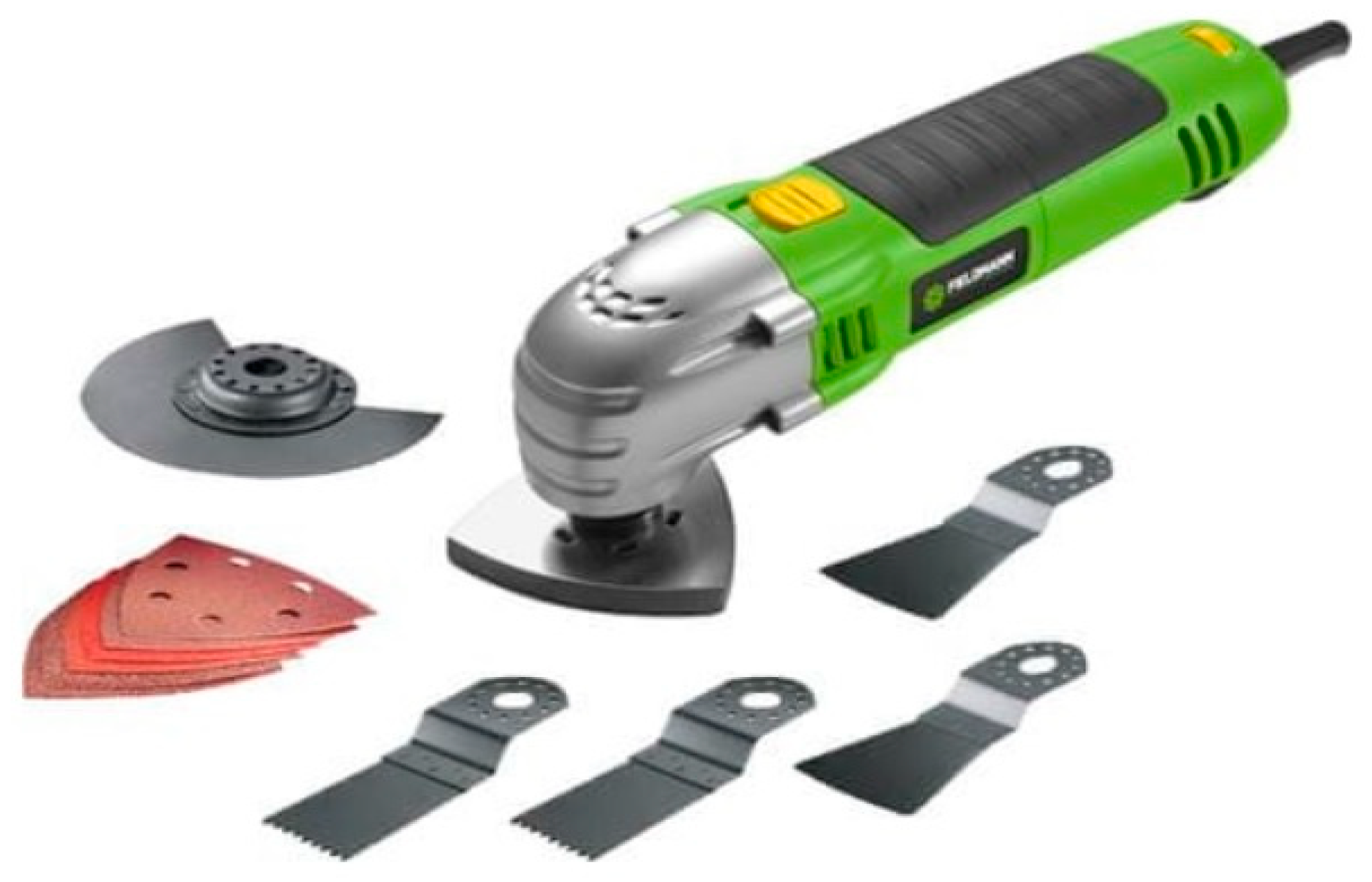
An example of such a process is the development of a bender for the production of a small number (100 pieces) of cutting blades for an oscillating cutter (Figure 1).
Multitool blades, also known as oscillating tool blades, oscillating multitool blades, or cutting blades, are attachments for oscillating power tools (also known as oscillating tools or oscillating multitools) that are used to cut, sand, and scrape various materials. They are designed to fit the oscillating head of the tool. The blades have a universal fit that allows them to be used with a wide range of different models of oscillating tools. Oscillating tool blades come in a variety of shapes and sizes and can be used for tasks such as cutting wood, metal, grout, fibre cement siding, and drywall, as well as sanding and scraping surfaces.
Oscillating blades are normally made of two parts, the blade holder and the blade cutting part, which are joined by spot welding. The blade holder is usually made by bending and punching. This method of manufacture is important in cases where different thicknesses of the holder and cutting edge are desired. The disadvantage is the need for a spot welder. For cases where the blade holder and the blade can be of the same thickness, it is advisable to design the production technology from a single blank without the need for spot welding.
This study aims to design an oscillating tool blade shape to cut soft materials and to separate bonded automotive glasses, which will have a clamping part with holes placed identically to the sample blade. A hardness of (54 to 57) HRC is required for newly designed cutting blades. The aim is to design economically advantageous technology for the production of this blade without spot welding from two parts, preferably from one blank. Other objectives are to formulate the material requirements for the blade and then to select a suitable blade material, to design a suitable blade shape in terms of bending using the equations for minimum and maximum bending radius, and to verify manufacturability by simulations in Dynaform, to design a low-cost bending tool for blade manufacturing by solving the guidance of the bender to the die, to design the method of setting the blank in the bending tool, to select a suitable method of annealing the blank before bending, and a suitable method of heat treating the fabricated blade to achieve the required strength, to verify the function of the designed and fabricated bending tool.
2. Materials and Methods
Cutting blade manufacturing technology was designed (see Section 2.1), that is, a suitable material for the cutting blade and a blank type were chosen (see Section 2.1.1), a new shape of the cutting blade was designed (see Section 2.1.2) and its developed shape was determined (see Section 2.1.3), a low-cost bending tool was designed (see Section 2.1.4). Furthermore, the feasibility of the proposed bending technology was validated by process simulations (see Section 2.2). In the end, the bending tool and, the test pieces of the cutting blade with a newly designed shape were produced (see Section 2.3).
2.1. Manufacturing Technology Project
2.1.1. Choice of a Cutting Blade Material and the Type of Blank
A variety of materials are used for oscillating tool blades depending on the type of material to be cut:
- High-carbon steel (HCS) standard blades are used for plunging and flush cuts in a wide range of materials, including drywall, hardwood floors, moulding, soft plastics, trim, and laminated materials. They are good for cutting softer wood, particle board, and plastics. However, they quickly dull when used on hardwood, metal, and other hard materials.
- High-speed steel (HSS) blades are made from hardened, high-grade, high-speed steel. These blades are used to cut harder materials, such as metal, aluminium, and non-ferrous metals.
- The bimetal (BIM) blades are with a content of 8% Cobalt. They are stronger than common HCS blades, making them harder materials. Bimetal is used to cut wood and nails. The titanium-enhanced carbide teeth blade is used to cut nails. Bimetal blades can cut ferrous or non-ferrous metals such as aluminium, brass, bronze, steel, stainless steel, and titanium. A carbide-tipped blade lasts much longer, cuts metal faster, and wears down much slower than its non-carbide counterpart.
- Oscillating diamond tool blades are used to remove grout.
To produce the cutting blade for cutting soft materials and for the separation of bonded automotive glasses, it was possible to choose the following materials:
(a) heat-treated high-carbon steel 1.1274 (EN-Code: C100S, ASTM/AISI: 1095) according to [28]. Chemical composition: C: max. 1.05%, Si: 0.15–0.30%, Mn: 0.30–0.45%, P: max. 0.02%, S: max. 0.02%, Cr: about 0.01%. Status: tempered, brightly polished. Contractual yield strength: Rp0.2 = 550 MPa. Tensile strength under tempered conditions: Rm = (1000 to 2000) MPa. Hardness: 60 HRC. Modulus of elasticity: E = 210 GPa. The tolerances for the dimensions and shape of the strip are according to [29]. Flatness max. 0.3% of the strip width. Edges: the widths of 6.0 mm and 12.7 mm have rounded edges for thicknesses greater than 0.25 mm, all other sizes have cut edges. Due to the high carbon content, which exceeds 1%, this alloy is ideal for feeler gauges, washers, and springs, where corrosion problems are not expected. Unhardened sheets are available as alloy 1.1248 (EN-Code: C75S, ASTM/AISI: 1075) according to [28] with tensile strength (490 to 650) MPa.
(b) heat-treated tool steel 1.2003 (EN-Code: 75Cr1, ASTM/AISI: 1075) according to [28]. Chemical composition: C: 0.70–0.80%, Si: 0.25–0.50%, Mn: 0.60–0.80%, P: max. 0.03%, S: max. 0.03%, Cr: 0.30–0.40%. Status: heat treated, unpolished. The tolerances for the dimensions and shape of the strip are according to [29]. Flatness: max. 0.2% of the strip width, cut edges. A small proportion of chromium leads to greater resistance to wear and better turbidity at greater widths. This alloy is suitable for small tools due to the hardness (47 to 51) HRC.
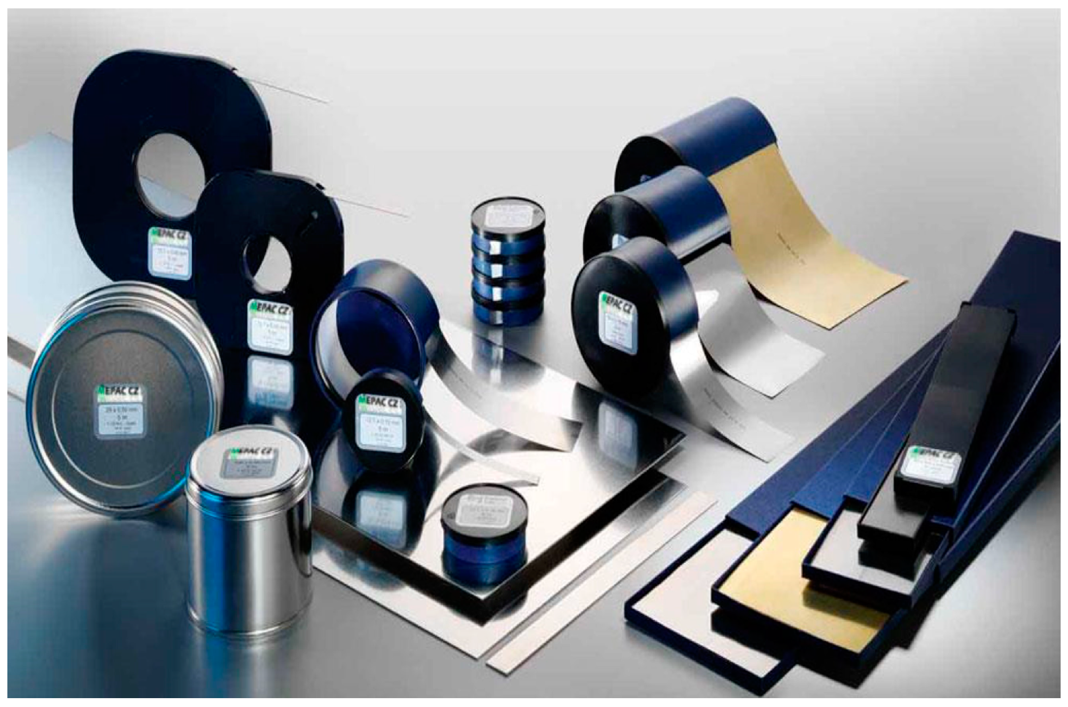
Since cutting blades will be used to cut soft materials and concerning the higher hardness value, the heat-treated high-carbon strip steel 1.1274 (Figure 2) according to [28] was chosen for the production of the cutting blade. The strip thickness of 0.6 mm was chosen.
Regarding the considerable strength of (1000 to 2000) MPa and the low plasticity stock of heat-treated high-carbon strip steel 1.1274 according to [28] the blank made of it needs to be softly annealed before bending and then after bending the blank in the bending tool to obtain the original values of mechanical properties of the material to perform the heat treatment, i.e., quenching and subsequent tempering to the required hardness (54 to 57) HRC.
2.1.2. Design of the Cutting Blade
The aim was to design the sharp scraper blade for the separation of bonded automotive glasses and for use in scraping and removing soft expansion joint silicone, caulking, window paste, and other sealing compounds, cardboard, carpet, rubber, and cutting insulation materials. The designed blade should be super thin and be shaped to allow access to corners and tight spaces. The clamping part of the blade should have the same dimensions and hole pattern as the mass-produced blades for the given oscillating cutter type. The aim was to design an economically viable technology for the production of about 100 pieces of this blade without spot welding from two parts, preferably from a single blank.
To design the clamping part of the cutting blade, the mass-produced multimaterial plunge cutting blade with a straight head (Figure 3) was used. This blade has high-speed steel teeth at the tip of the blade. It is suitable for cutting wood, plastic, fibreglass, nails, non-ferrous metals, thin sheet metal, and hardened fillers. The cutting blade consisted of two parts—the blade holder and the blade cutting part, the parts were spot-welded to each other. The thickness of the blade was 0.5 mm and the thickness of the holder was 1.5 mm.
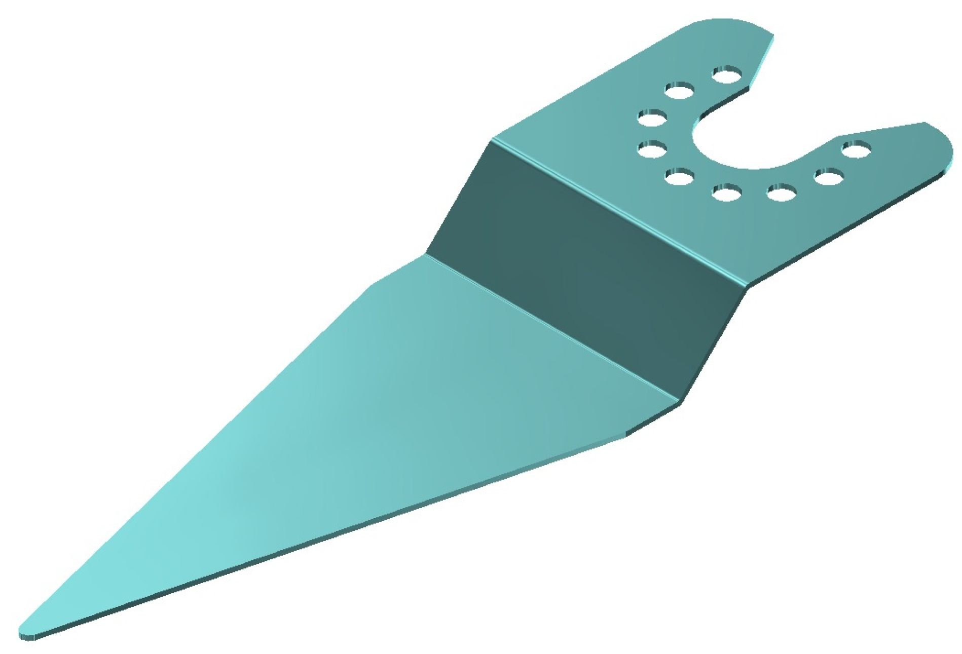
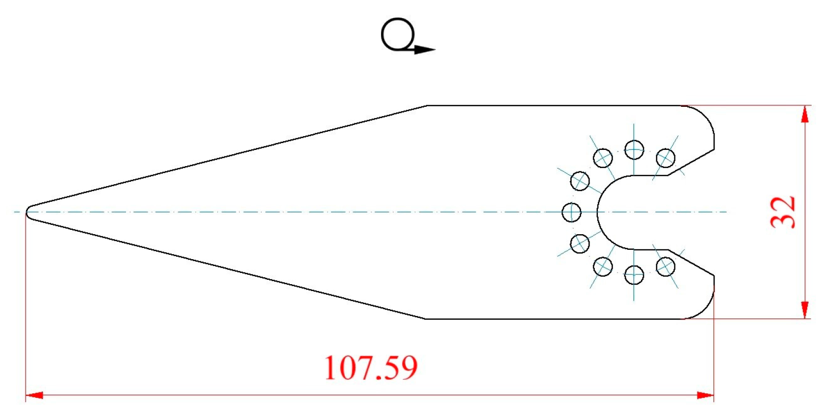
Before the design of the forming tool, the shape of the cutting blade was designed. For access to corners and tight spaces, the tapered blade point design with the cutting edge on the lateral sides of the blade (Figure 4) was designed, so it was possible to produce the blade holder and the blade cutting part from one blank piece.
For both bends, in the designed shape of the cutting blade, the smallest recommended internal bend radius at which the material does not break (the tensile stress in the outer fibres must not exceed the tensile strength of the material Rm) was calculated according to Equation (1). The size of the smallest recommended internal bend radius also depends on the orientation of the bend due to the rolling direction (if the axis of the bend is in the direction of material fibres, the value of rmin is about 2× larger than the value of rmin when the bend axis is perpendicular to the direction of the fibres. Small radii of the curvature in the bend area cause greater deformation and use of plasticity stock, but the parts have lower springback after bending.
The smallest recommended internal bend radius:
where εm (–) is the maximum uniform proportional deformation at stress on tensile strength and s (mm) is the thickness of the bent material.
The maximum uniform proportional deformation at stress on tensile strength can be approximately determined from the following equation:
Based on the calculated value of the minimum internal bend radius of Equation (1) for both bends in the designed shape of the cutting blade, the internal bend radius r = 0.6 mm was chosen, that is, the lowest value so that the springback will be small. Validation of the possibility of use of this radius without the formation of cracks on the outer side of the bend was carried out by simulations in the Dynaform 5.2.1 software, which uses the finite element method (see Section 2.2) and subsequently by bending the annealed blank of the cutting blade in a bending tool (see Section 3.3).
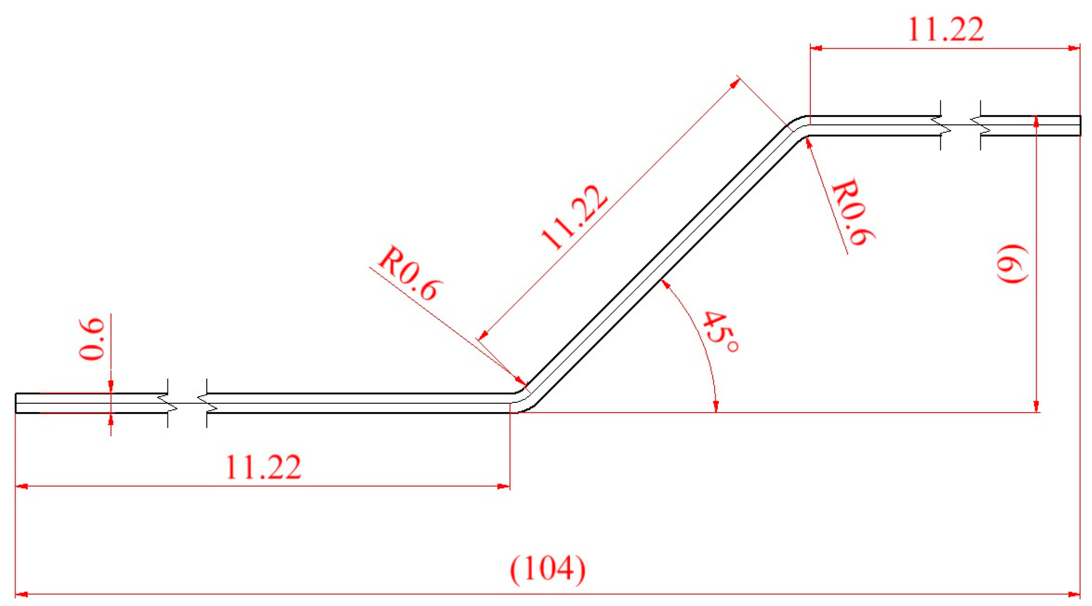
For both bends in the designed shape of the cutting blade (Figure 5) the largest radius of bend allowed according to Equation (3) was calculated. It is the radius of bend at which the permanent deformation occurs in the outermost fibres of the bent cross section on the tension side. When using the values of the radius of the bend larger than this value, the bend would be flexible and the material would be straightened out after unloading again.
The largest allowable bend radius:
where s (mm) is the thickness of the bent material, E (MPa) is the modulus of elasticity in the tension of the bent material, and Re (MPa) is the significant yield point of the bent material.
For both bends, the designed shape of the cutting blade (Figure 5) was calculated according to Equation (4) the minimum length of the bent arm.
The minimum length of the bent arm:
amin = 2 s = 2 · 0.6 = 1.2 mm
In the designed shape of the cutting blade (Figure 5) the calculated value of Equation (4) is not lower.
The springback after bending will take effect by increasing the bending radius and decreasing the bending angle. The springback after bending arises due to the elastic stress accompanying each cold forming. It is enhanced when the material is harder and when the bend radius is greater (it is reduced as the bend angle increases). The springback can be limited or excluded by the plastification of the bend area, which leads to the reduction or exclusion of the elastic deformation area.
The springback angle after bending:
where β (°) is the springback angle, l (mm) is the distance between the outer rigging of the bending die, k (–) is the coefficient indicating the position of the neutral layer depending on the ratio of r/s (for r/s = 1 is k = 0.44), and r (mm) is the inner radius of curvature in the bending area and thickness s (mm) of the blank for bending.
At both bends in the designed shape of the cutting blade (Figure 5) the springback will be identical and, due to it, even after springback, the parallelism of the blade section that serves as the holder with the cutting part of the blade maintained, which is important for functionality.
In the design of the bent part, the following technological principles were kept:
- The axes of both bends were designed perpendicular to the direction of rolling of the material.
- The axes of both bends have directions perpendicular to the part contour.
- Small bending radii were chosen to reduce the springback.
- Greater springback of the material is also prevented by the choice of bending technology by embossing.
- For the blank during bending to not move in the bending tool, the blank is established and fixed in the initial position by two locating pins with the use of positioning holes around the circumference of the holder part of the cutting blade.
- Pre-made positioning holes around the circumference of the holder part of the cutting blade will not be deformed during bending because the condition is kept that their boundaries lie at least at a distance of a = s from the bend area.
2.1.3. Developed Shape of Designed Cutting Blade
For both bends, at the designed shape of the cutting blade, the initial length of the material was calculated. The lower the angle between the bent arms, the more the neutral layer is shifted to the bend axis.
- The approximate calculation according to [30]:
The developed length of the neutral layer arc for opening angles of α = (90 to 150)° can be calculated from the formula:
where r (mm) is the inner radius of the curvature in the bending area, s (mm) is the thickness of the blank for bending, and α (°) is the opening angle, i.e., between the bent arms.
- 2.
- The approximate calculation using the coefficient of neutral layer displacement in Autodesk Inventor 2023 software:
The design cut blade shape (Figure 6) was constructed using Autodesk Inventor software and subsequently developed with the use of the coefficient k = 0.44, which considers the displacement of the neutral layer in the bending area and the consequent elongation of the material in the bending area. The value is valid for stainless steel, which can be used in other materials with higher tensile strength, which is the case for the heat-treated high-carbon steel strip 1.1274 according to [28] selected for the production of cutting blades.
Developed length in the bending area:
where φ (°) is the bending angle, r (mm) is the inner radius of the curvature at the bending area, k (−) is the coefficient considering the neutral layer in the bending area, which is chosen in the range of 0.30 to 0.50 while larger values are used for large bending angles, and s (mm) is the thickness of the blank for bending.
The coefficient considering the displacement of the neutral layer in the bending area has the following meaning:
where sv (mm) is the distance of the neutral layer from the inner radius of curvature at the bending area, and s (mm) is the thickness of the blank for bending.
- 3.
- Precision calculation using the coefficient of neutral layer displacement:
The neutral layer displacement coefficient can be calculated using the following equation:
The radius of the neutral layer:
where r (mm) is the inner radius of the curvature in the bending area and s (mm) is the thickness of the blank for bending.
Bend angle:
where α (°) is the opening angle, i.e., between the bent arms.
Arc length of the neutral layer, i.e., developed length in the bending area:
The exact value of the coefficient taking into account the displacement of the neutral layer in the bending area k to verify the method (b) listed above can be calculated using the displacement coefficient of the neutral layer of x calculated according to Equation (9):
It follows from this that the use of the coefficient k = 0.44 in Autodesk Inventor software brought only a small difference that corresponds to the rounding to two decimal places.
The initial length of the material for bending is the sum of the separate parts:
where Li (mm) is the length of the i-th neutral layer arch and ai (mm) is the length of the i-th straight section.
2.1.4. Design of a Low-Cost Bending Tool
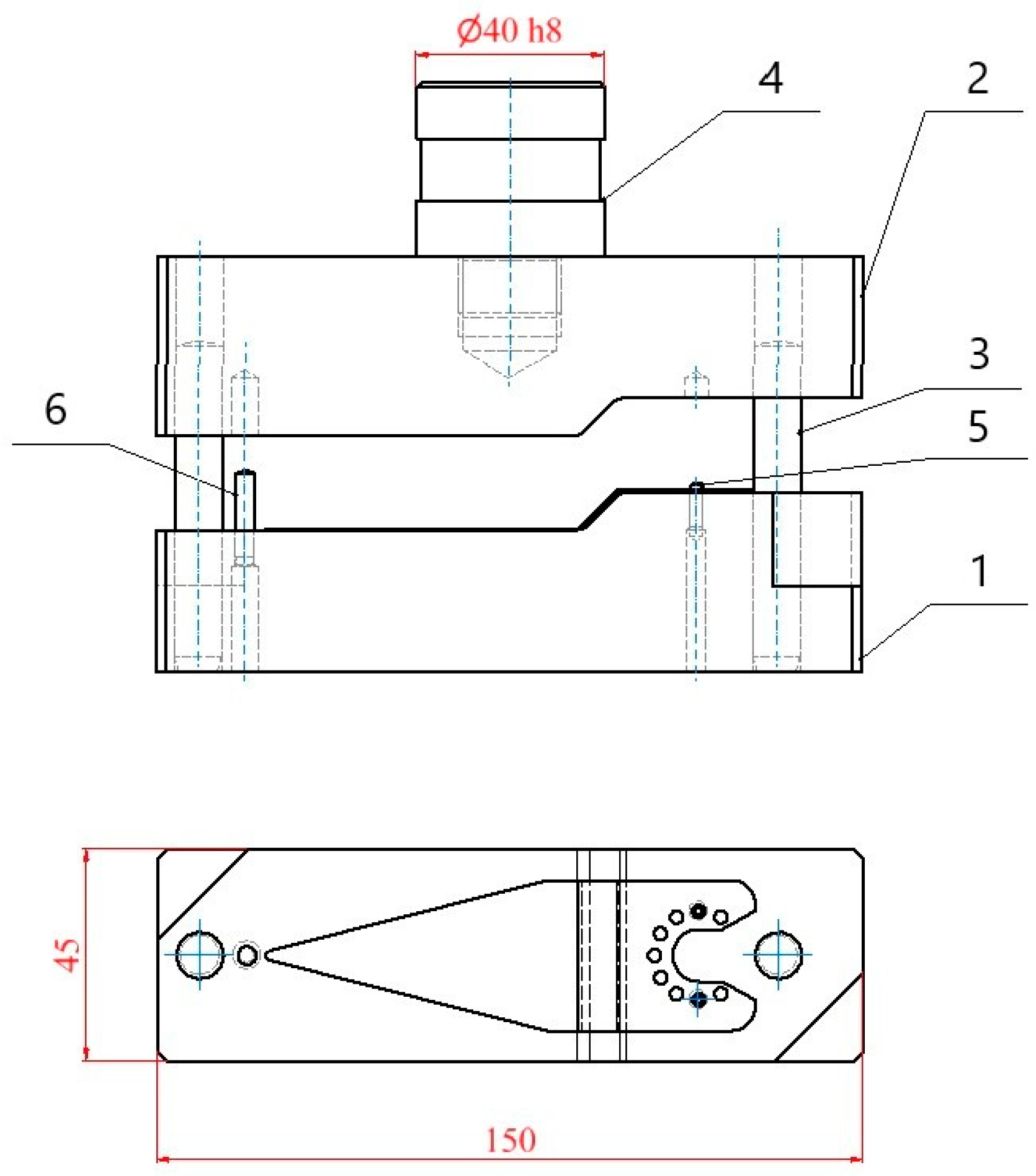
As a result of the low number of pieces required for the cutting blade, it was not appropriate to choose the standard progressive forming technology due to the high production costs. As the most economically advantageous solution, the utilisation of a screw press with manual control to its working zone a simple forming tool (bending tool) will be fastened consisting of the lower part of the bending tool 1, the upper part of the bending tool 2, the guide pillars 3 and the clamping shank 4 (see Figure 7).
The upper part of the bending tool 2 is also the clamp plate, where the top is the tapped hole M20 to secure the clamping shank 4 for the press ram. The lower part of bending tool 1 is simultaneously a foundation plate that will be clamped using the clamps to the press table. Both working parts of the bending tool move relative to each other exactly due to the guide pillars 3 (dowel pin hardened 10 × 70—A—St according to [31] from chrome-vanadium tool steel, hardness (60 ± 2) HRC, fine ground—tolerance h6, without surface treatment) with push-fit of H7/h6 without lubrication (Figure 7).
The lower part of bending tool 1 was to be completed by two locating pins 5 (cylindrical pin of unhardened steel 3 × 12 according to [32]) to establish and consolidate the blank using positioning holes around the circumference of the part of the cutting blade holder and the auxiliary stop 6 (cylindrical pin hardened 4 × 20—A—St according to [31] of chrome–vanadium tool steel, hardness (60 ± 2) HRC, fine ground—tolerance m6, without surface treatment) to prevent change of the blank position before landing of the upper part of bending tool 2. Due to an auxiliary stop 6, the blank inserted into the forming tool is held in a horizontal position so that it does not fall by its weight before the upper part of the bending tool 2.
The geometry of the active parts of the bending tool was designed for bending with embossing, so the upper part of the bending tool 2 and the lower part of the bending tool 1 have an angle corresponding to the requested bend angle. This option is used only when bending on presses, in contrast to plain bending without embossing, when the tool parts have a universal shape and the upper part of the bending tool has a lower angle than the lower part of the bending tool, which has an angle corresponding to the requested bend angle.
For the production of the upper part of bending tool 2 and the lower part of bending tool 1, steel 19,312 (alternatively, steel 19,573 can be used) was chosen. The clamp shank 4 for the press ram was made of steel 11,600. The mentioned materials were chosen according to their standard use for the manufacture of tool parts.
The roughness of the work surfaces of the bending tool was designed at Ra = 3.2 μm. The blank for the production of the upper part of bending tool 2 has dimensions of (45 × 50 − 155) mm, and the blank for the production of the lower part of bending tool 1 has dimensions of (45 × 50 − 160) mm.
The separate parts of the bending tool were machined on the five-axis milling machine. Because the main objective was to achieve a low cost of the forming tool for the small number of pieces of cutting blades specified, the heat treatment of the working parts of the tool was not proposed. Grinding of the tool parts after hardening was also eliminated.
Guide pillars 3 and auxiliary stop 6 were designed as standardised cylindrical hardened pins, and two locating pins 5 were designed as standardised cylindrical pins from unhardened steel, so there was no need to produce any of them.
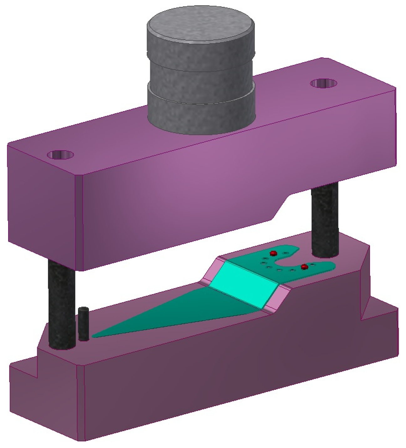
The model of the bending tool for the production of the cutting blades of the oscillating cutter is shown in Figure 8.
2.2. Numerical Simulations
An analysis of cutting blade manufacturing technology was carried out using numerical simulations.
The developed shape of the designed cutting blade of the oscillating cutter (Figure 8) was loaded into Dynaform 5.2.1 software, which uses the finite element method (FEM). A mesh of elements was formed on the blank, with a size of 3 mm selected.
For simulation of the forming process, steel 1.4521 (X2CrMoTi18-2) was selected from the Dynaform 5.2.1 material library, which has properties very similar to annealed steel 1.1274 according to [28], from which the cutting blades of the oscillating cutter will be produced (see Section 2.1.1).
The simulation was carried out for the material parameters: the contractional yield strength Rp0.2 = 336 MPa, the ultimate strength Rm = 450 MPa, the ductility A5 = 20%, and the modulus of elasticity E = 220 GPa. This material is very similar to the chosen material of the cutting blade of the oscillating cutter (see Section 2.1.1). Since the aim of the simulations was to analyse cutting blade manufacturing technology, the use of this material for the simulations did not affect the general results of the analysis.
In the simulations, the shear friction coefficient µ = 0.28 was used.
The calculation was based on the Krupkowski mathematical model in which the actual stress is calculated according to the equation: ϭ = K·(ε0 + εp)n with the following values: material constant K = 842.5 MPa, relative elastic deformation ε0 = 0.009679, strain hardening exponent n = 0.199597. The value of εp in the equation is a relative plastic deformation.
Simulation of the bending process of the designed cutting blade was carried out, and then in the postprocessor, the separate analyses were displayed (see Section 3.2).
2.3. Experiments
According to the construction project (see Section 2.1.4), the low-cost bending tool was manufactured for the production of the cutting blades of the oscillating cutter.
The blank for the production of the cutting blade (see Figure 6) was made of heat-treated high-carbon steel 1.1274 according to [28]. Hard metal tools predrilled holes around the circumference of the part of the cutting blade holder to attach to the oscillating cutter as technological holes with an accuracy of ±0.02 mm.
When drilling, five pieces of blanks were clamped together. The shape of the cutting blade was later made by the MAKINO wire cutter, while five pieces of blanks were clamped together. In the same way, predrilled positioning holes were finished around the circumference of the holding part of the cutting blade to clamp to the oscillating cutter. The diameter of the cutting wire was 0.3 mm. The shape of the cutting blade was orientated according to the direction of the rolling of the steel strip so that future bend lines were perpendicular to the direction of rolling.
Before the cutting blade blank was bent, the blank had to be annealed because of its considerable strength and low-plasticity stock. The blank was soft-annealed (heating in a vacuum furnace with subsequent cooling in a second furnace).
The cutting blade blank was bent with the low-cost bending tool (see Section 2.1.4).
After bending the annealed blank of the cutting blade in the bending tool (Figure 7) to obtain the original values of the mechanical properties of the material, the heat treatment was applied, that is, hardening and subsequent tempering to the desired hardness of (54 to 57) HRC. Hardening was carried out in PARAMO TK 46 hardening oil. It is a high-quality hardening oil composed of a selected deeply refined, very pure base oil and additives to achieve the prescribed hardening characteristics of thermal and thermo-oxidative stability. The tempering was carried out at 480 °C and was kept at that temperature for 35 min. Because the blades were heated in the vacuum furnace, the scale does not appear on their surface.
3. Results
3.1. Results of the Manufacturing Technology Project
Cutting blade manufacturing technology was designed (see Section 2.1), that is, a suitable cutting blade material and a blank type were chosen (see Section 2.1.1), and a suitable shape of the cutting blade was designed according to the purpose of its use (see Section 2.1.2), and its developed shape was determined (see Section 2.1.3), a low-cost bending tool was designed (see Section 2.1.4).
For the production of the cutting blade of the oscillating cutter, the heat-treated high-carbon steel 1.1274 (EN-Code: C100S, ASTM/AISI: 1095) according to [28] with a thickness of 0.6 mm (see Section 2.1.1) which was chosen as a blank since the cutting blade will be used to cut soft materials and due to its high hardness value.
Before forming the tool design, the shape of the cutting blade of the oscillating cutter was designed. For access to corners and tight spaces, the tapered blade point design was designed with the cutting edge at the lateral sides of the blade according to customer requirements. The production of the blade holder and the blade cutting part from one piece of blank will be possible (see Section 2.1.2).
The minimum bending radius was calculated. The inner radii of r = 0.6 mm were designed concerning the thickness of the material, which is s = 0.6 mm (see Section 2.1.2). Using Autodesk Inventor software, the shape of the proposed shape of the designed cutting blade was constructed (see Section 2.1.3).
Due to the low number of cutting blades required to be manufactured, the use of a manual-controlled screw press was applied. In its working zone, a simple forming tool (bending tool) will be clamped. It is the most economically advantageous solution. The design of the bending tool was made for the production of the cutting blade of the oscillating cutter (see Section 2.1.4). The roughnesses of the work surfaces were designed of Ra = 3.2 µm. Because the main objective was to achieve a low cost of production of the forming tool for the production of the specified small number of cutting blade pieces, the heat treatment of the parts of the tool used was not proposed.
3.2. Results of the Simulations
The simulation of the bending process of the designed cutting blade was carried out with input values mentioned in Section 2.2, and then in the postprocessor, separate analyses were displayed.
Analysis of the deformations at the bending of the designed cutting blade of heat-treated high carbon steel 1.1274 according to [28] and the resulting manufacturability of the part is shown in Figure 9. From the figure, it is seen that the highest values of equivalent stress of 343.7 MPa are in places of bending. Since heat-treated high-carbon steel 1.1274 according to [28] has a tensile strength of (1000 to 2000) MPa, the value is safe, so no extreme plastic deformation localisation occurs.
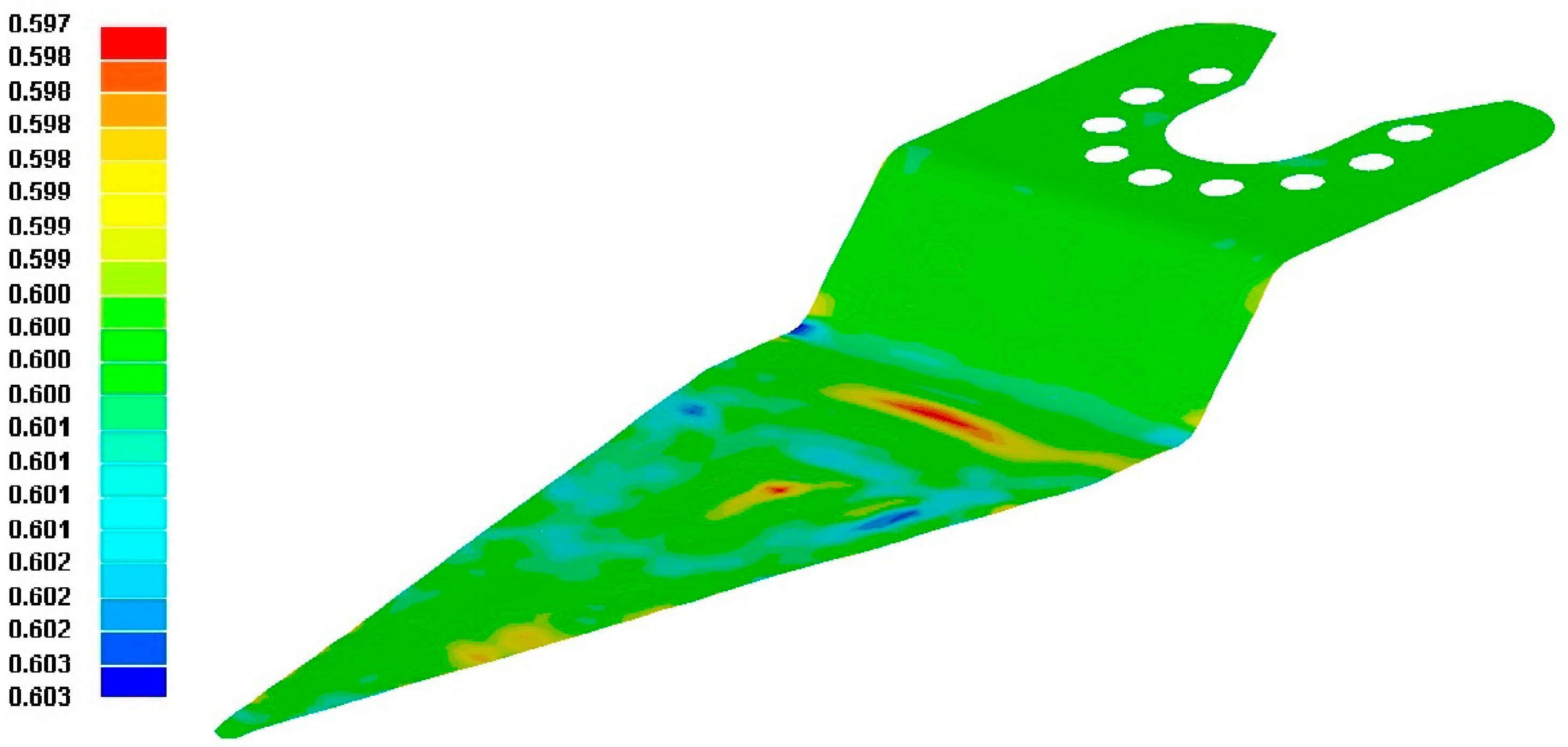
The thickness analysis after bending the designed cutting blade of the oscillating cutter of the treated high carbon steel 1.1274 according to [28] is shown in Figure 10. From the figure, it is seen that the lowest value of the thickness after bending 0.583 mm is in the place of bending. Since the treated high carbon steel 1.1274 according to [28] has an initial thickness of 0.6 mm, the maximum value of the thinning after bending is 0.017 mm.
The greater the thinning of the material in the bending areas, the greater the angle of the bending, the greater the friction between the material and the tool, the smaller the radius of the bending, and the lower the formability of the material. Undue material thinning at the place of the sharp bend can be prevented only by the previous creation of the material stock.
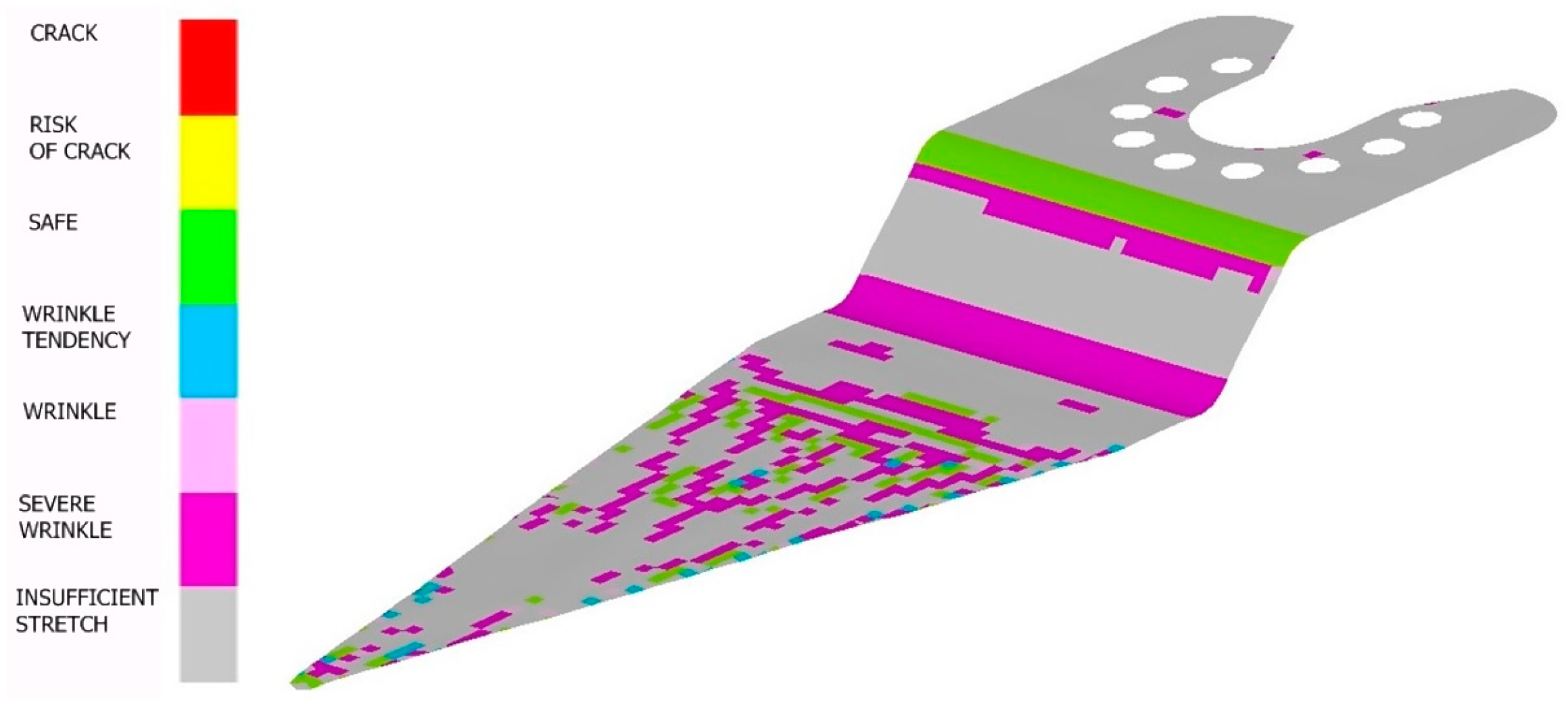
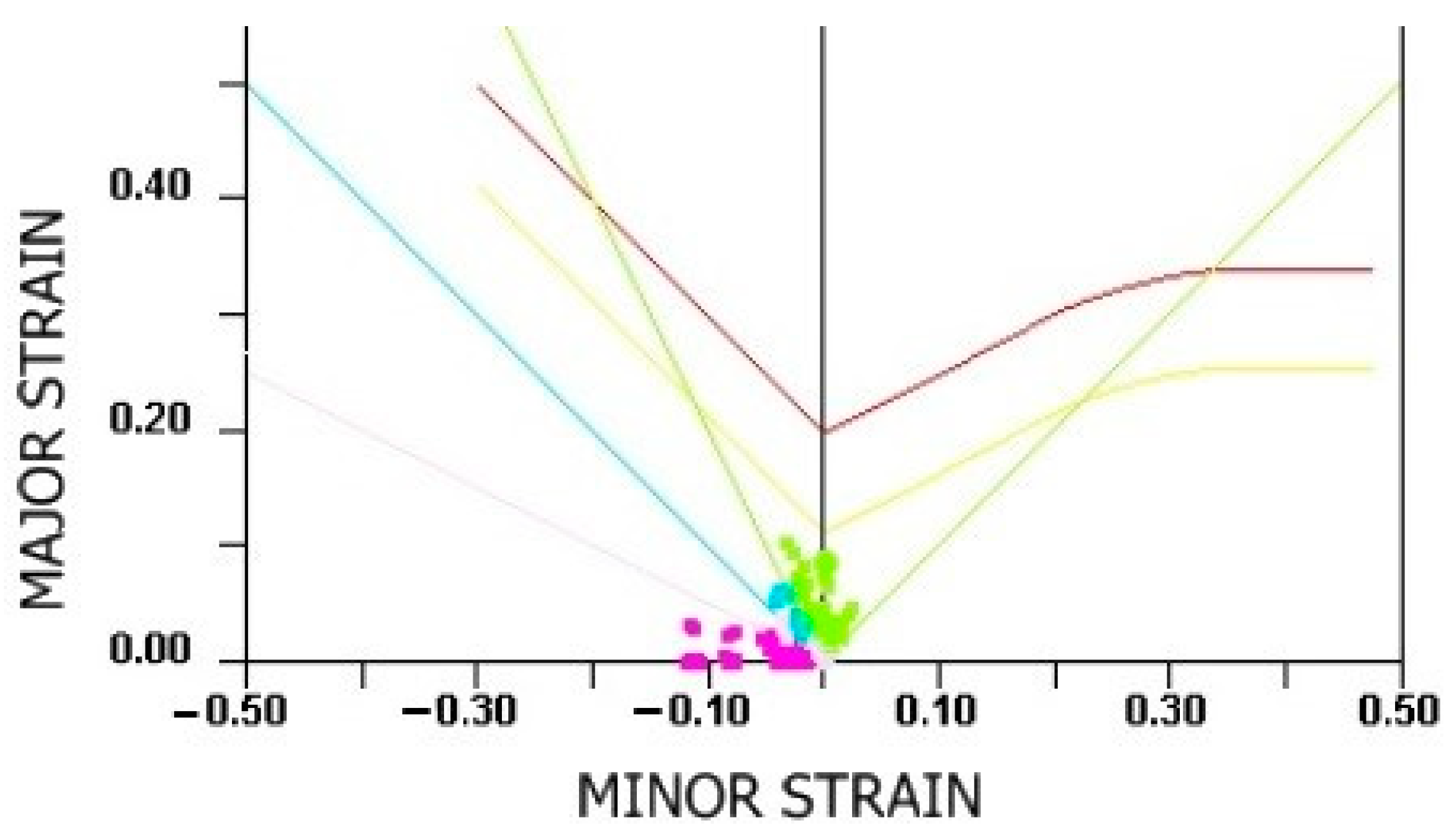
Analysis of the formability of the designed cutting blade of heat-treated high-carbon steel 1.1274 according to [28] was carried out using the sheet metal forming limit diagram used (Figure 11) related to the analysis of deformations at bending (Figure 9). From the displayed values of the main logarithmic deformations in the bend area, which are found at the bottom of the diagram, it is seen that the designed bending is safe, so without the risk of extreme local thinning or crack in the bend area.
The simulations showed that extreme plastic deformation localisation does not occur when bending the blade, the maximum value of thinning after bending is 0.017 mm in the place of bending, and the values of the main logarithmic deformations in the bend area are at the bottom of the forming limit diagram of the blade material, so the designed bending is without risk of arising extreme local thinning or crack asking in the bend area. Thus, it has been verified that the designed bending is safe and that the designed shape of the cutting blade should not be modified.
3.3. Results of the Experiments
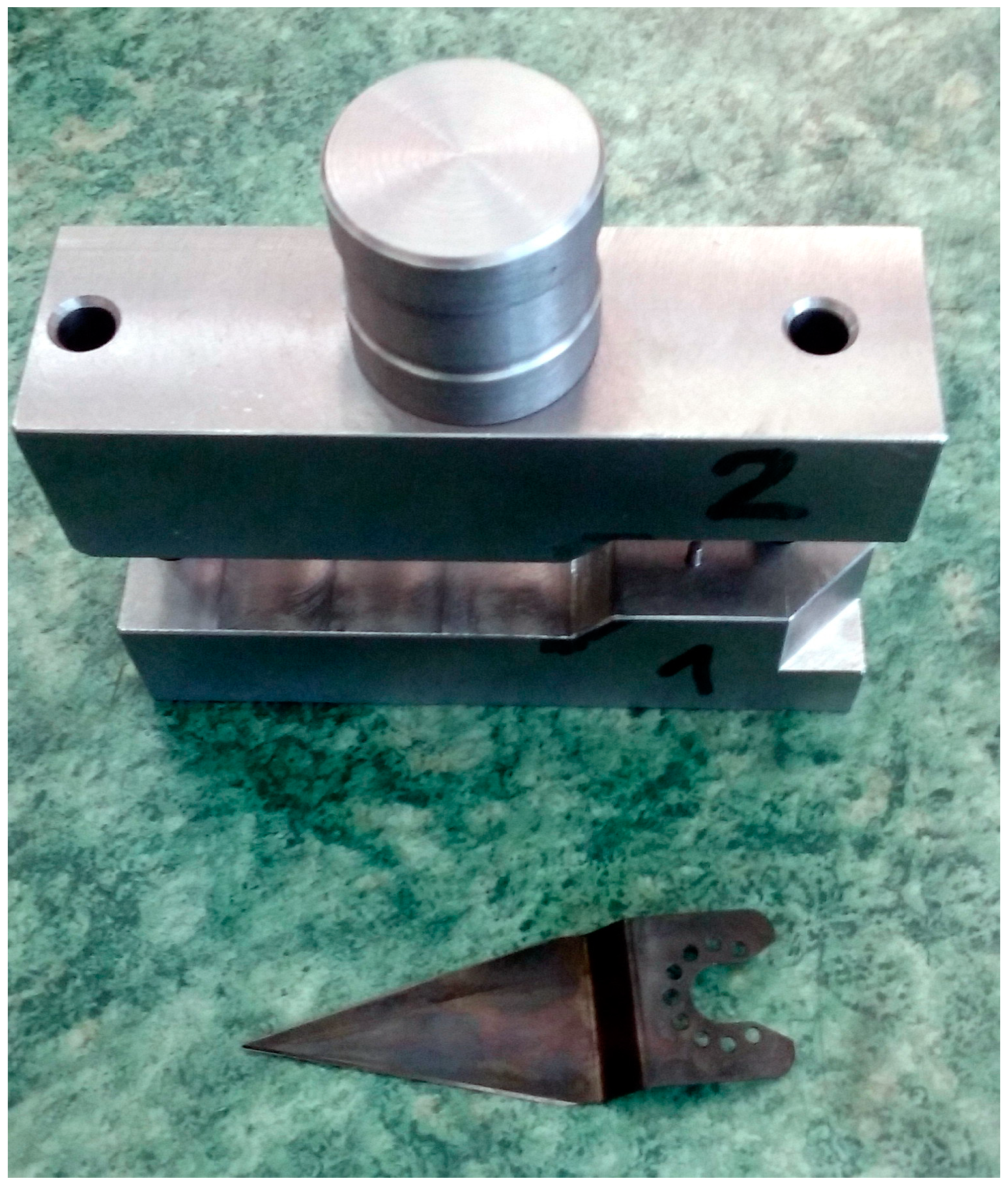
The proposed low-cost bending tool (Figure 12) was attached to the ram of a hand-held spindle press in the dead centre of the bottom of the ram.
The subsequent production of the test pieces of cutting blades of the oscillating cutter in a low-cost designed bending tool verified its functionality.
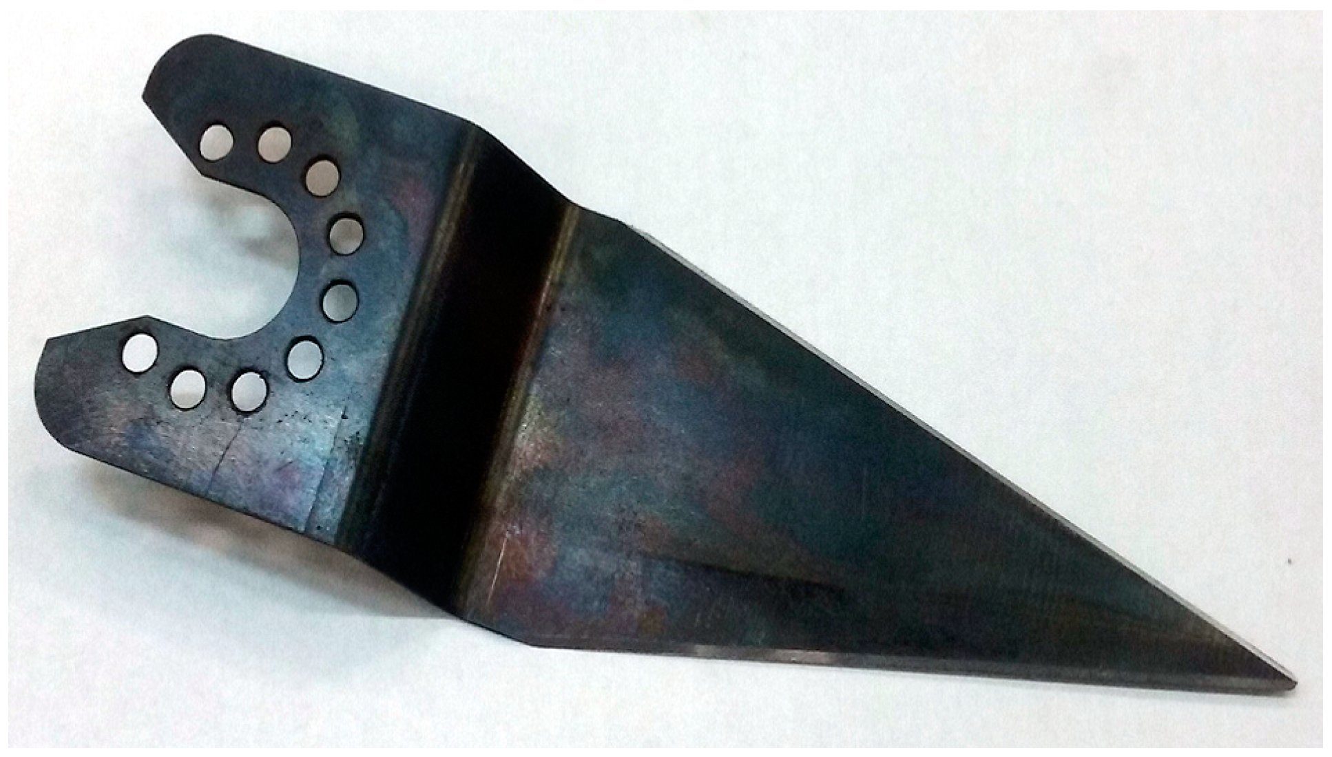
The final product of the cutting blade of the oscillating cutter made with the designed bending tool is shown in Figure 13.
Through hardness tests, it was verified that the final product of the cutting blade of the oscillating cutter has, after heat treatment, a hardness of 56 HRC, which is a value in the range of (54 to 57) HRC requested by the customer.
4. Discussion
The design of the cutting blade material must be carried out taking into account the type of material to be cut and the required hardness of the blade (see Section 2.1.1).
The design of the cutting blade must be done with respect to the application. In the present case, for access to corners and tight spaces, the tapered blade point design was designed with the cutting edge on the lateral sides of the blade (see Section 2.1.2).
In the design of the bent part, it is useful to calculate and take into account the smallest recommended internal bend radius, the largest allowable bend radius, the minimum length of the bent arm, and the springback angle after bending (see Section 2.1.2).
Before manufacturing the forming tool, it is useful to verify the designed manufacturing technology by simulations in a program using the finite element method to eliminate the risk of arising defects in the forming process (see Section 2.2 and Section 3.1).
In the solved case of manufacturing the cutting blades of the oscillating cutter after the project of manufacturing technology, the rigid metallic forming tool (see Section 2.1.4) was manufactured and, by it, the test pieces of the cutting blade (see Section 3.3) by which the correct function of the designed bending tool was successfully checked.
The use of a rigid metallic forming tool was chosen to achieve small bending radii with sufficient accuracy, to achieve the parallelism of both bends and also for economic reasons. The use of rigid metallic forming tools is suitable in most companies because they usually have a tool room in which such a tool can be produced. Rigid metal tools are capable of transmitting higher forces, which is important when forming a material with a greater thickness or when a greater force is required to bend the material. Metallic materials tend to deform less than plastic materials during the forming process, which can help maintain the accuracy and repeatability of production. Metal tools tend to have a greater wear resistance than plastic tools. This is crucial when materials of high hardness or an abrasive nature are regularly processed. Metal tools can be used at higher temperatures without the risk of deformation or permanent damage, which is important when forming materials that require elevated temperatures. Metal tools can often be more easily maintained and repaired, contributing to lower maintenance costs and longer tool life.
Another alternative to a rigid metal forming tool is the production with a hydraulic or mechanical press brake [33,34]. This alternative can be considered if the company already has such a machine and would incur only the cost of a bender and die for this type of machine. In the case of the manual feeding of the blank, it would be difficult to achieve the parallelism of both bends. The advantage of manufacturing with a hydraulic or mechanical press brake is the flexibility to create different shapes and sizes, which is useful in cases where product shapes change frequently.
To reduce tooling costs, rubber or flexible tools can be used together with one rigid metallic die or punch, to enforce a predictable and repeatable geometry of the stamped parts. If the complete tooling setup is built with deformable tools, the quality and geometry of the final part are hardly predictable and only prototypal production is generally possible [35].
The use of unfilled or reinforced plastic materials for the production of forming tools [17,18,19] can be more difficult for a company due to the need for a solution in cooperation with another company. As a rule, it is not worth taking a one-at-a-time solution for a single forming tool, but it can be considered when dealing with multiple types of forming tools. Plastic materials are generally lighter than metals, which can be advantageous if the reduction of tool weight is important. Plastics can also be easier to machine, which makes it easier to produce complex shapes. Plastics usually do not have as high mechanical strength as metals. This can be a problem when forming harder or stronger materials [36]. Plastic materials can be more susceptible to wear than metals [37,38], especially with repeated use or when working with abrasive materials. Rigid metallic tools typically offer longer tool life than plastic tools, which is important when producing larger quantities of parts.
Compared to conventional forming processes, the use of a flexible tool with polyurethane [20,21,22,39] requires only one fixed die according to the shape of the part and the second tool is replaced by a rubber pad. A holder of solid or laminated rubber pads should be made. For the case at hand, the method was not suitable because, using rubber as the pressure-carrying medium, the lack of sufficient forming pressure results in parts with less sharpness.
Regarding the considerable strength of (1000 to 2000) MPa and the low plasticity stock of heat-treated high carbon strip steel 1.1274 according to [28], the blank made from it needs to be soft-annealed before bending and then after bending the blank in the bending tool to obtain the original values of the mechanical properties of the material to carry out the heat treatment, i.e., quenching and subsequent tempering to a required hardness.
Through hardness tests, it was verified that the final product of the cutting blade has, after heat treatment, a hardness of 56 HRC, which is a value in the required range of (54 to 57) HRC.
5. Conclusions
The procedure for designing the technological process of production and the forming tool presented in this paper can be applied in cases where it is necessary to design an appropriate production technology for a small number of parts by forming to achieve the minimum price of one piece of the manufactured part.
The use of a rigid metallic forming tool is usually the most suitable solution because of the achievement of small bending radii with sufficient precision, the greater durability of the forming tool compared to tools made of plastic materials, and also because most companies have a tool room where such a tool can be cheaply produced and subsequently maintained. Metallic materials, such as steel or hard alloys, can provide the appropriate hardness and durability required to form a wide range of materials, including high-strength metals.
To avoid great thinning or cracking during bending in the design of a bent part, it is useful to calculate and take into account the smallest recommended internal bend radius, the largest allowable bend radius, the minimum length of the bent arm, and the springback angle after bending. Simulating the behaviour of materials during the bending process also helps refine the design and select suitable manufacturing parameters.
The bending solution methodology allows for the design and modelling of bending operations to achieve the desired shapes. When working with materials of different properties, such as different ductility or hardness, the methodology can be used to optimise the bending process for each specific material. The methodology of material bending solutions is important in minimising material suspension, which is important in cases where precise dimensions must be achieved after bending.
The effective application of the material bending solution methodology requires accurate input data on material, geometry, and process conditions. Some simulation tools and analyses can be costly, especially for smaller companies or individuals. Combining the simulation methodology with experience can lead to successful results in real industrial applications.
Based on experiments, it was verified that if the main aim is to achieve a low cost of production of the forming tool for the specified small number of cutting blade pieces, the heat treatment of the tool working parts can be eliminated, and, by that, the grinding of the tool working parts after their hardening is also eliminated.
Based on experiments, it was verified that at steels with a considerable strength of (1000 to 2000) MPa and low plasticity stock, the blank made from it needs to be soft annealed before bending and then after bending the blank in the bending tool to obtain the original values of the mechanical properties of the material to carry out the heat treatment, i.e., hardening and subsequent tempering to the required hardness.
Further work may be aimed at comparing the results of bending with a rigid metallic forming tool and bending with one or both parts of the plastic forming tool, comparing the wear of the rigid metallic forming tool and the plastic tool, and determining the effect of the material of the tool on the surface quality of the formed part.
Author Contributions
Conceptualization, R.Č. and T.P.; methodology, R.Č.; software, R.Č.; validation, T.P.; formal analysis, R.Č.; investigation, R.Č. and T.P.; resources, R.Č.; data curation, T.P.; writing—original draft preparation, R.Č.; writing—review and editing, R.Č.; visualization, T.P.; supervision, R.Č. All authors have read and agreed to the published version of the manuscript.
Funding
This article was supported by a Czech project No. SP2023/020 with the name ‘Research and Optimisation of Engineering Technologies’ financed by the Ministry of Education, Youth and Sports of the Czech Republic.
Institutional Review Board Statement
Not applicable.
Informed Consent Statement
Not applicable.
Data Availability Statement
Data is contained within the article.
Conflicts of Interest
The authors declare no conflict of interest.
References
- Emmens, W.C. Bending. In Formability, 1st ed.; SpringerBriefs in Applied Sciences and Technology; Springer: Berlin/Heidelberg, Germany, 2011; pp. 25–32. [Google Scholar] [CrossRef]
- Gan, W.; Wagoner, R.H.; Mao, K.; Price, S.; Rasouli, F. Practical Methods for the Design of Sheet Formed Components. J. Eng. Mater. Technol. 2004, 126, 360–367. [Google Scholar] [CrossRef]
- Tekiner, Z. An experimental study on the examination of springback of sheet metals with several thicknesses and properties in bending dies. J. Mater. Process. Technol. 2004, 145, 109–117. [Google Scholar] [CrossRef]
- Ahmed, G.M.S.; Ahmed, H.; Mohiuddin, M.V.; Sajid, S.M.S. Experimental Evaluation of Springback in Mild Steel and its Validation Using LS-DYNA. Procedia Mater. Sci. 2014, 6, 1376–1385. [Google Scholar] [CrossRef]
- Grizelj, B.; Cumin, J.; Grizelj, D. Effect of Spring-Back in V-Tool Bending of High-Strength Steel Sheet Metal Plates. Metalurgija 2012, 52, 99–102. [Google Scholar]
- Eggertsen, P.A.; Mattiasson, K. On the modelling of the bending-unbending behaviour for accurate spring-back predictions. Int. J. Mech. Sci. 2009, 51, 547–563. [Google Scholar] [CrossRef]
- Tekaslan, Ö.; ¸Seker, U.; Özdemir, A. Determining springback amount of steel sheet metal has 0.5 mm thickness in bending dies. Mater. Des. 2006, 27, 251–258. [Google Scholar] [CrossRef]
- Trieu, Q.-H.; Vuong, G.-H.; Nguyen, D.-T. Predictive Modeling of Spring-Back Behavior in V-Bending of SS400 Steel Sheets under Elevated Temperatures Using Combined Hardening Laws. Appl. Sci. 2023, 13, 10347. [Google Scholar] [CrossRef]
- Hsu, T.C.; Shien, I.R. Finite element modeling of sheet forming process with bending effects. J. Mater. Process. Technol. 1997, 63, 733–737. [Google Scholar] [CrossRef]
- Chou, I.N.; Hung, C. Finite element analysis and optimization on springback reduction. Int. J. Mach. Tools Manuf. 1999, 39, 517–536. [Google Scholar] [CrossRef]
- Cada, R. Comparison of formability of steel strips, which are used for deep drawing of stampings. J. Mater. Process. Technol. 1996, 60, 283–290. [Google Scholar] [CrossRef]
- Evin, E.; Tomas, M. Comparison of deformation properties of steel sheets for car body parts. Procedia Eng. 2012, 48, 115–122. [Google Scholar] [CrossRef]
- Evin, E.; Tomas, M.; Kmec, J.; Nemeth, S.; Katalinic, B.; Wessely, E. The Deformation Properties of High Strength Steel Sheets for Auto-Body Components. Procedia Eng. 2014, 69, 758–767. [Google Scholar] [CrossRef]
- Otzurk, F.; Dilmec, M.; Turkoz, M.; Ece, R.E.; Halkaci, H.S. Grid Marking and Measurement Methods for Sheet Metal Formability. In Proceedings of the 5th International Conference and Exhibition on Design and Production of Machines and Dies/Molds, Aydin, Turkey, 18–21 June 2009. [Google Scholar]
- Mantyjarvi, K.; Tulonen, J.; Saarnivuo, T.; Porter, J.; Karjalainen, J.A. Grid patterns by laser for forming strain analysis. Int. J. Mater. Form. 2008, 1, 249–252. [Google Scholar] [CrossRef]
- Cada, R. Evaluation of strain and material flow in sheet-metal forming. J. Mater. Process. Technol. 2003, 138, 170–175. [Google Scholar] [CrossRef]
- Zaragoza, V.G.; Strano, M.; Iorio, L.; Monno, M. Sheet metal bending with flexible tools. Procedia Manuf. 2019, 29, 232–239. [Google Scholar] [CrossRef]
- Souza, J.H.C.; Liewald, M. Analysis of the tribological behavior of polymer composite tool materials for sheet metal forming. Int. J. Sci. Technol. Frict. Lubr. Wear 2010, 268, 241–248. [Google Scholar] [CrossRef]
- Nakamura, N.; Mori, K.I.; Abe, F.; Abe, Y. Bending of sheet metals using plastic tools made with 3D printer. Procedia Manuf. 2018, 15, 737–742. [Google Scholar] [CrossRef]
- Ramezani, M.; Ripin, Z.M.; Ahmad, R. Sheet metal forming with the aid of flexible punch, numerical approach and experimental validation. CIRP J. Manuf. Sci. Technol. 2010, 3, 196–203. [Google Scholar] [CrossRef]
- Thiruvarudchelvan, S. Elastomers in metal forming: A review. J. Mater. Process. Technol. 1993, 39, 55–82. [Google Scholar] [CrossRef]
- Thiruvarudchelvan, S. The potential role of flexible tools in metal forming. J. Mater. Process. Technol. 2002, 122, 293–300. [Google Scholar] [CrossRef]
- Lin, Z.C.; Chang, D.Y. The selection system for sheet bending tooling. Int. J. Adv. Manuf. Technol. 1996, 11, 127–135. [Google Scholar] [CrossRef]
- Stefanovska, E.; Pepelnjak, T. Development of a flexible tooling system for sheet metal bending. Adv. Prod. Eng. Manag. 2022, 17, 311–325. [Google Scholar] [CrossRef]
- Gan, W.; Wagoner, R.H. Die design method for sheet springback. Int. J. Mech. Sci. 2004, 46, 1097–1113. [Google Scholar] [CrossRef]
- Karafillis, A.P.; Boyce, M.C. Tooling design in sheet metal forming using springback calculations. Int. J. Mech. Sci. 1992, 34, 113–131. [Google Scholar] [CrossRef]
- Tavodova, M.; Hnilica, R. Assessment of Selected Properties of Treated Tool Surfaces Examined to Increase Tool Life Time. Manuf. Technol. 2020, 20, 257–264. [Google Scholar] [CrossRef]
- BS EN 10132:2021; Cold-Rolled Narrow Steel Strip for Heat Treatment—Technical Delivery Conditions. European Committee for Standardization: Brussels, Belgium, 2021. Available online: https://www.technickenormy.cz/bs-en-10132-2021-cold-rolled-narrow-steel-strip-for-heat-treatment-technical-delivery-conditions/ (accessed on 3 February 2023).
- BS EN 10140:2006; Cold-Rolled Narrow Steel Strip. Tolerances on Dimensions and Shape. European Committee for Standardization: Brussels, Belgium, 2006. Available online: https://www.technickenormy.cz/bs-en-10140-2006-cold-rolled-narrow-steel-strip-tolerances-on-dimensions-and-shape/ (accessed on 3 February 2023).
- CSN 01 7009:1975; Calculation of Unfolded Lengths of Inflected Parts. Czechoslovak Office for Standardization: Prague, Czech Republic, 1975. Available online: https://www.technicke-normy-csn.cz/csn-01-7009-017009-160747.html (accessed on 7 February 2023).
- UNE EN ISO 8734:1998; Parallel Pins, of Hardened Steel and Martensitic Stainless Steel (Dowel Pins)—General Information. European Committee for Standardization: Brussels, Belgium, 1998. Available online: https://www.technickenormy.cz/une-en-iso-8734-1998-parallel-pins-of-hardened-steel-or-martensitic-stainless-steel-dowel-pins-iso-8734-1997/ (accessed on 3 February 2023).
- BS EN ISO 2338:1998; Parallel Pins of Unhardened Steel and Austenitic Stainless Steel. European Committee for Standardization: Brussels, Belgium, 1998. Available online: https://www.technickenormy.cz/hledani/?q=EN+ISO+2338 (accessed on 3 February 2023).
- Mentink, R.J.; Lutters, D.; Streppel, A.H.; Kals, H.J.J. Determining material properties of sheet metal on a press brake. J. Mater. Process. Technol. 2003, 141, 143–154. [Google Scholar] [CrossRef]
- Miranda, S.S.; Barbosa, M.R.; Santos, A.D.; Pacheco, J.B.; Amaral, R.L. Forming and springback prediction in press brake air bending combining finite element analysis and neural networks. J. Strain Anal. Eng. Des. 2018, 53, 584–601. [Google Scholar] [CrossRef]
- Iorio, L.; Pagani, L.; Strano, M.; Monno, M. Design of Deformable Tools for Sheet Metal Forming. J. Manuf. Sci. Eng. Trans. ASME 2016, 138, 094701. [Google Scholar] [CrossRef]
- Park, Y.; Colton, J.S. Failure analysis of rapid prototyped tooling in sheet metal forming-V-die bending. J. Manuf. Sci. Eng. Trans. ASME 2005, 127, 116–125. [Google Scholar] [CrossRef]
- Park, Y.; Colton, J.S. Sheet metal forming using polymer composite rapid prototype tooling. J. Eng. Mater. Technol. Trans. ASME 2003, 125, 247–255. [Google Scholar] [CrossRef]
- Benabdallah, H.S. Static friction coefficient of some plastics against steel and aluminum under different contact conditions. Tribol. Int. 2007, 40, 64–73. [Google Scholar] [CrossRef]
- Prete, A.D.; Papadia, G.; Manisi, B. Computer Aided Modelling of Rubber Pad Forming Process. In Proceedings of the 14th International Conference on Sheet Metal (SHEET METAL 2021), Leuven, Belgium, 18–20 April 2011. [Google Scholar] [CrossRef]
Figure 1.
Oscillating cutter with replaceable cutting blades (source: www.fieldmann.cz (accessed on 2 February 2023)).
Figure 1.
Oscillating cutter with replaceable cutting blades (source: www.fieldmann.cz (accessed on 2 February 2023)).

Figure 2.
Heat-treated high-carbon strip steels with different thicknesses supplied by the company MEPAC CZ, Ltd., Trinec, Czech Republic (source: https://www.mepac.cz/wp-content/uploads/2022/09/Planzety.pdf (accessed on 2 February 2023)).
Figure 2.
Heat-treated high-carbon strip steels with different thicknesses supplied by the company MEPAC CZ, Ltd., Trinec, Czech Republic (source: https://www.mepac.cz/wp-content/uploads/2022/09/Planzety.pdf (accessed on 2 February 2023)).

Figure 3.
Multimaterial plunge cutting blade with a straight head consisting of two spot-welded parts.
Figure 3.
Multimaterial plunge cutting blade with a straight head consisting of two spot-welded parts.

Figure 4.
The designed shape of the tapered cutting blade consisting of one piece.

Figure 5.
Side view of the designed movable cutting blade of the oscillating cutter.

Figure 6.
Developed shape of the designed cutting blade of the oscillating cutter.

Figure 7.
Design of the bending tool for the production of the cutting blades of the oscillating cutter (1—the lower part of bending tool, 2—the upper part of the bending tool, 3—the guide pillars, 4—clamping shank, 5—two locating pins, 6—auxiliary stop).
Figure 7.
Design of the bending tool for the production of the cutting blades of the oscillating cutter (1—the lower part of bending tool, 2—the upper part of the bending tool, 3—the guide pillars, 4—clamping shank, 5—two locating pins, 6—auxiliary stop).

Figure 8.
Model of the bending tool for the production of the cutting blades of the oscillating cutter.
Figure 8.
Model of the bending tool for the production of the cutting blades of the oscillating cutter.

Figure 9.
Analysis of deformations at bending of the designed cutting blade of the oscillating cutter from heat-treated high-carbon steel 1.1274 according to [28] and the resulting manufacturability of the part.
Figure 9.
Analysis of deformations at bending of the designed cutting blade of the oscillating cutter from heat-treated high-carbon steel 1.1274 according to [28] and the resulting manufacturability of the part.

Figure 10.
Analysis of thickness after bending the designed cutting blade of the oscillating cutter from treated high-carbon steel 1.1274 according to [28].
Figure 10.
Analysis of thickness after bending the designed cutting blade of the oscillating cutter from treated high-carbon steel 1.1274 according to [28].

Figure 11.
Analysis of the manufacturability of the designed cutting blade of the oscillating cutter from heat-treated high-carbon steel 1.1274 according to [28] with the use of the forming limit diagram of the sheet metal used.
Figure 11.
Analysis of the manufacturability of the designed cutting blade of the oscillating cutter from heat-treated high-carbon steel 1.1274 according to [28] with the use of the forming limit diagram of the sheet metal used.

Figure 12.
Bending tool for the production of the cutting blades of the oscillating cutter (top) and a part made by it (bottom).
Figure 12.
Bending tool for the production of the cutting blades of the oscillating cutter (top) and a part made by it (bottom).

Figure 13.
The cutting blade of the oscillating cutter made by the designed bending tool.

Disclaimer/Publisher’s Note: The statements, opinions and data contained in all publications are solely those of the individual author(s) and contributor(s) and not of MDPI and/or the editor(s). MDPI and/or the editor(s) disclaim responsibility for any injury to people or property resulting from any ideas, methods, instructions or products referred to in the content. |
© 2023 by the authors. Licensee MDPI, Basel, Switzerland. This article is an open access article distributed under the terms and conditions of the Creative Commons Attribution (CC BY) license (https://creativecommons.org/licenses/by/4.0/).
Share and Cite
MDPI and ACS Style
Čada, R.; Pektor, T. Design of the Production Technology of a Bent Component. Appl. Sci. 2023, 13, 13033. https://doi.org/10.3390/app132413033
AMA Style
Čada R, Pektor T. Design of the Production Technology of a Bent Component. Applied Sciences. 2023; 13(24):13033. https://doi.org/10.3390/app132413033
Chicago/Turabian StyleČada, Radek, and Tomáš Pektor. 2023. "Design of the Production Technology of a Bent Component" Applied Sciences 13, no. 24: 13033. https://doi.org/10.3390/app132413033
Note that from the first issue of 2016, this journal uses article numbers instead of page numbers. See further details here.