1. Introduction
In an era where the urgency to mitigate greenhouse gas emissions has reached a critical point, the aviation industry stands as a significant contributor to the global carbon footprint. Presently, aviation is responsible for approximately 2.4% of worldwide CO
2 emissions [
1], a statistic that could undergo alarming escalation if air traffic triples by 2050, potentially causing aviation-related emissions to constitute a staggering 20% of global warming pollutants [
2]. Addressing this dire scenario necessitates radical advancements in aircraft design and propulsion technology, driven by a commitment to drastically reduce the environmental impact of flight [
3,
4,
5,
6,
7].
The introduction of electrical propulsion represents a pivotal turning point in aeronautical engineering, heralding a new chapter of environmentally conscious innovation. Amid this backdrop, organizations like NASA and the Department of Energy have set ambitious benchmarks for motor power density in electric aircraft—a crucial step towards achieving commercially viable electric flight [
8,
9]. As the aviation landscape evolves, the spotlight is increasingly trained on the concept of distributed propulsion systems, a design strategy that promises to usher in enhanced energy efficiency, diminished carbon emissions, reduced operational costs, and even reduced acoustic noise levels [
10,
11].
This transformation towards electrification is not merely a theoretical endeavor. Rather, it is propelled by major industry players including NASA, Boeing, Airbus, Joby Aircraft, and Lilium, who are directing substantial investments towards the development of electric airplane technologies [
9,
12,
13,
14]. A pivotal aspect of this evolution lies in the utilization of fans powered directly by electric motors, offering a simpler and more versatile alternative to traditional propulsion systems. Notably, the collaborative efforts of these industry giants have yielded promising outcomes in the field of fixed-wing distributed propeller and electric ducted fan aircraft designs.
A central tenet of this transition to electric aviation involves the pursuit of high-speed flight capabilities with electric motor technology—a challenge that is being squarely addressed by initiatives like NASA’s drive towards electric aircraft motors with exceptional power density and efficiency [
14]. Furthermore, the market’s growing anticipation of electric aviation’s market entry has fortified research and development endeavors, nurturing a fertile ground for the exploration of new possibilities and real-world applications. Electric airplanes, when compared to their traditional counterparts, often employ fans powered directly by electric motors. This system is significantly less intricate than turboprop engines, creating opportunities for more individualized propulsion system configurations that can be fine-tuned to enhance the capabilities of a particular aircraft. NASA, Joby Aircraft, and Lilium’s investment in fixed-wing distributed propeller and electric ducted fan aircraft designs has proven to be fruitful [
9]. The research and development of these designs have enabled us to explore new possibilities and increase the practical application of electric aviation technology [
15].
In order to achieve subsonic speeds for commercial flight, major civil aircraft manufacturers worldwide are adopting comparable methods that rely on hub-driven electric ducted fan technology [
13]. Nevertheless, it is widely acknowledged that employing large centralized electric ducted fan (EDF) propulsion and traditional aircraft wing and body configurations introduces inefficiencies in both electrical supply and aerodynamics, which could hinder the overall effectiveness of electric-powered aircraft [
16]. The benefits of electric propulsion, including blended wing body and distributed thrust systems, become more evident when contrasted with conventional design approaches [
17,
18].
Ducted fan technology, which has been a staple since the 1960s, has now witnessed a transformative advancement in the form of rim-driven fan (RDF) technology. This innovation, which eschews the conventional motor designs in favor of a more compact and efficient approach, offers the potential to revolutionize the way aircraft propulsion is conceptualized and engineered. By embodying a unique rotor configuration that departs from traditional center hub designs, RDF technology not only enhances thrust and exhaust air velocity but also ushers in opportunities for more streamlined and effective designs.
As the aviation industry treads the path of electrification, the innovative prowess of rim-driven fan technology emerges as a beacon of hope, pointing towards a more sustainable and efficient future for air travel. The potential of rim-driven fan technology to revolutionize aircraft propulsion is a central theme in the subsequent sections. By embracing the unique rotor configuration that sets RDF technology apart, we unlock opportunities for enhanced thrust and exhaust air velocity while streamlining designs for increased effectiveness.
This collective effort to explore the untapped potential of rim-driven fan technology is a vital step towards reconciling aviation’s impact on the environment. By addressing the core challenges and opportunities that this technology presents, we are contributing to the larger mission of reducing carbon emissions and building an eco-friendlier aviation landscape. The journey to fully realizing the promise of rim-driven fan technology is an ongoing narrative, one that aligns seamlessly with the broader narrative of a sustainable and innovative aviation future.
In the pages that follow, we delve deeper into the intricacies of rim-driven fan technology, exploring its principles, benefits, and the potential it holds for shaping the future of aviation propulsion. The leading sections of the document focus on providing readers with an overview of the RDF jet and its key features and benefits. This includes the rim-driven configuration and various concepts that underpin the design and development of the engine. The article also explores the innovation and evolution of the RDF jet, including the different types of electric motors, the design considerations, and the noise and vibration issues that have been addressed. The control mechanisms used, the bearing technology employed, and the use of FEA and CFD in the development process are also discussed.
The article concludes with a brief summary of the main points covered, highlighting the significance of RDF technology as a driving force in reshaping aviation propulsion. As the industry moves forward, propelled by the momentum of electrification, the lessons and insights from this exploration will undoubtedly play a pivotal role in defining the trajectory of aviation’s environmental transformation.
2. Features and Benefits of the RDF Jet
The ducted fan concept, which uses a rotor to generate thrust enclosed in a cover, has been used since the 1960s and is widely used in manned aircraft. Electric ducted fan (EDF) is the same concept, but the rotor is driven by an electric motor. EDF offers advantages including high thrust-to-weight and thrust-to-diameter ratios, physical and environmental protection, and thrust vectoring. Design parameters, such as the end clearance and outlet opening to fan area ratio, affect performance parameters such as thrust, RPM, energy consumption, efficiency, and noise [
19]. Hence, compact electric ducted fan (EDF) modules enable the integration of propulsion configurations that distribute thrust, yet their usage remains confined to scenarios involving low-speed flight, like those observed in general aviation and small unmanned aerial systems. Owing to their design centered around a central hub, diminutive single-stage rotors necessitate exceedingly elevated rotational velocities to attain higher exhaust airspeeds, a limitation that poses significant challenges [
20,
21,
22].
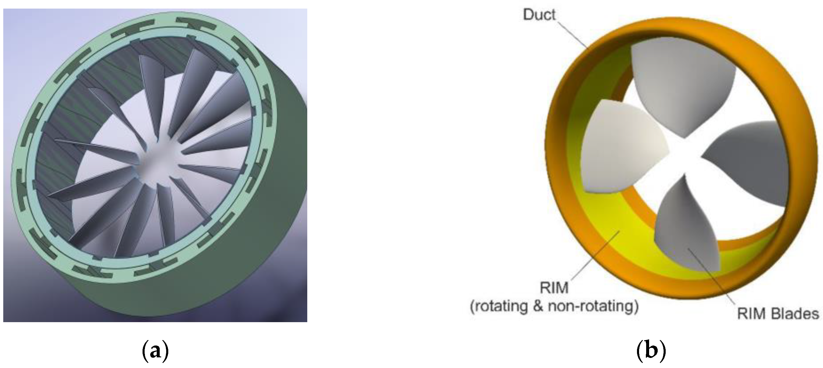
However, rim-driven fan (RDF) technology has emerged as a possible solution. In contrast to conventional motor designs, this technique allows for smaller fan inlet diameters while still producing significant thrust and exhaust air velocity. The rim-driven fan (RDF), rim-driven thruster (RDT), or rim-driven propulsor/propeller (RDP) is an innovative electric propulsion unit. Unlike conventional propellers, which have a center hub through which the driving torque is transmitted, rim-driven thrusters only have a rotating outer ring [
23]. In contrast, the blades of a rim-driven thruster are not attached to a central hub but rather to an outer ring. The electric motor’s rotor, which is the ring, rotates inside the stator, which is also a ring, to provide the required torque. The stator of the electric motor is installed in the duct, and the rotor forms a ring around the propeller’s rim in this innovative design (
Figure 1).
In recent years, the maritime sector has witnessed the emergence of a promising ship propulsion option—the shaftless rim-driven thruster (RDT) [
24]. The concept of propulsion being driven by its rim is not a recent innovation. As far back as 1957, the idea of a mechanically rim-driven ship’s propeller had been proposed [
25]. Since then, rim-driven propeller (RDP) devices for both surface and underwater vessels have become commercially available [
24], thanks to the widespread adoption of electrical rim drives in marine applications. Nevertheless, references to rim-driven technologies have been comparatively scarce within the automotive and aerospace industries, particularly with regards to aviation. The advancement of rim-driven fan (RDF) technology for aerospace applications has encountered a more gradual pace of development. This lag may be attributed to various factors, including the challenges associated with larger base forms and rotating component masses, technical complexities, and limitations in the available technology at the time. These factors might have contributed to the comparative absence of rim-driven concepts in the aerospace field.
Figure 1.
(
a) Layout of a rim-driven fan (RDF), (
b) configuration of a rim-driven propeller [
26] (Copyright (2023), with permission from Elsevier).
Figure 1.
(
a) Layout of a rim-driven fan (RDF), (
b) configuration of a rim-driven propeller [
26] (Copyright (2023), with permission from Elsevier).
Nonetheless, recent technological advancements have reshaped this landscape. Progressions in computerized modeling and analysis methods, developments in materials science, the emergence of 3D prototyping, advancements in unmanned aircraft system (UAS) technology, and breakthroughs in power electronics and electric propulsion systems have jointly driven the progress and assessment of motorized RDFs for aerospace applications, including within the domain of unmanned aircraft. These developments have substantially reduced barriers that once hindered progress. While potential challenges and intricacies are outlined in the subsequent sections, the momentum gained through technological strides suggests that the incorporation of electric motors in aviation might offer a viable solution to the imperative of electrifying airplanes. As the aviation industry strives to adopt greener and more sustainable practices, the journey toward the realization of efficient and effective rim-driven fan technology has the potential to be a game-changer in the pursuit of environmentally conscious aerial transportation.
Rim-Driven Configuration
RDFs are primarily distinguished by their shaftless architecture as opposed to traditional motor-propeller designs (
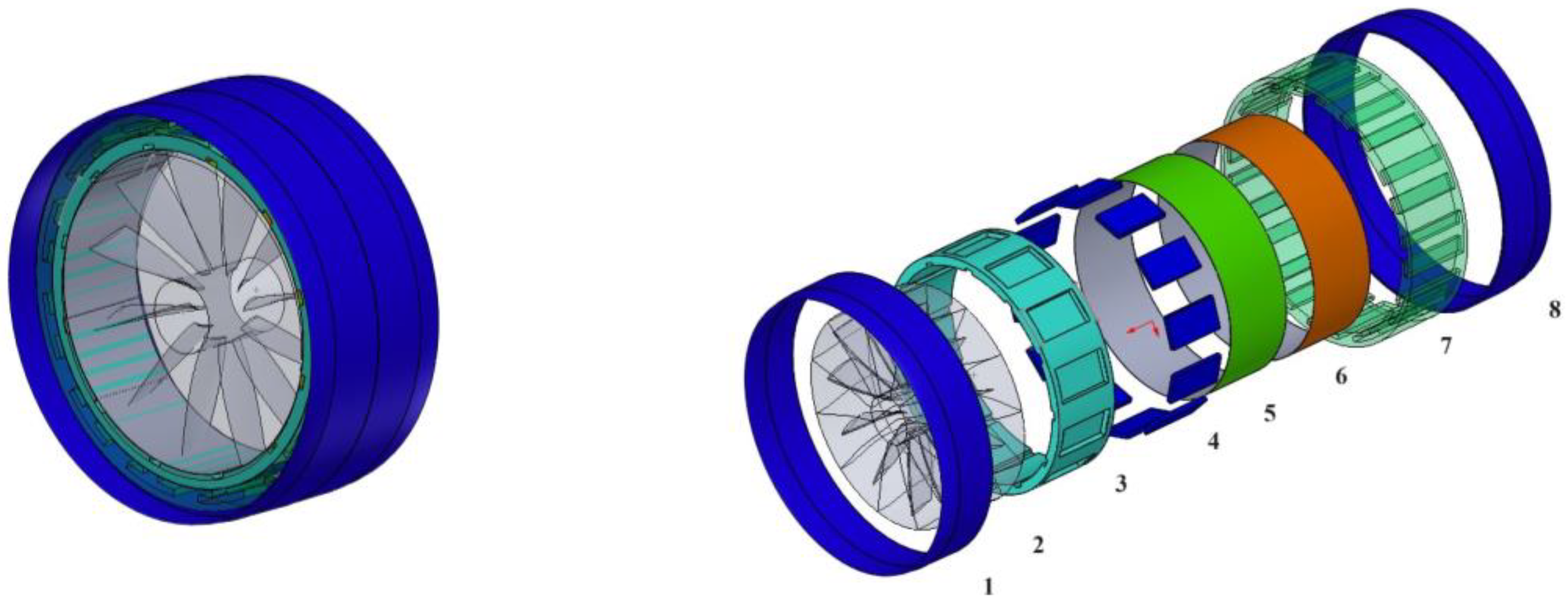
Figure 1). A ducted fan drum rotor with attached blades at the outer diameter makes up the actual arrangement. The rotor is housed inside a stator, and it is powered by electromagnetic fields that are modulated between the two components. The controller and power electronic drive circuits between the power source and integrated motor assembly provide optimal modulation. The rotor assembly is suspended and supported by magnetic fields inside the stator (
Figure 2).
Using torque applied to the drum rotor, which has blades mounted on the revolving shell, the levitated ducted fan, a self-contained electromagnetic propulsor, generates thrust. Using the large surface area and unique physical dimensions of the rotor’s outer circle is essential for developing the most efficient electromagnetic levitation and propulsion mechanism between the rotor and stator. Key to this concept is the novel application of electromagnetic propulsion and the non-contact support system.
The fan blades in a rim-driven propeller or turbofan are rotated by the rim, rather than an axis. Under the dynamic magnetic force between the inner rim and outer ring/shell magnets, the rim spins. High-intensity permanent magnet plates, which have no electrical connections, are implanted in the rotor’s inner rim. These stators, which are induced by an external power source, are effectively controlled by a high-power circuit. Hence, the stators within the rim of the RDF jet are supplied with significant electrical energy and are regulated through the utilization of a robust and powerful circuitry system. This is how RDF is able to distribute power from the rim to the blades without going via the central shaft. Therefore, more air can enter because there is no central shaft to restrict it.
Utilizing a rim-driven method rather than an axis-driven one makes it much easier to resist high torque. Direct power transfer is another distinction between rim-driven and axis-driven systems. With a typical fan, the original driving force is delivered in a two-step indirect way from the turbine to the shaft to the fan blade. Meanwhile, the rotor’s power is sent directly from the rim to the fan blade in an RDF. Its greater drivability enables a thicker blade to revolve faster and more easily to satisfy the resistive torque generated by the RDF jet engine’s high thrust output.
Unlike traditional jet engines that use gas turbines or diesel, the RDF uses an electric motor. Modern electric motor technology is used in the rim-driven motor, drastically increasing its power output per unit of weight. The RDF jet is able to utilize materials with a low specific density. Fiber-reinforced composite (FRC) plastic, ceramic matrix composite metal (CMC), new alloys, and many other composites can be used in the production of housings, wheels, and fans, respectively. Integrating these cutting-edge advances allows the RDF jet to be constructed while meeting stringent mass requirements.
RDF jets are compact cubic cylinders with easy installation and alignment. Hence, the implementation of distributed electric propulsion (DEP) can be straightforwardly achieved through the deployment of multiple RDF jets distributed across the entirety of the aircraft. Propulsion systems can harness the advantageous interactions between aerodynamics and propulsion, surpassing the capabilities of traditional setups due to their adaptable placement, scaling, and operational versatility [
27,
28].
The shaftless motor, embedded turbofan, inner-duct channel, and tail jet propulsion are all cleverly combined into a cylinder by the RDF jet and can be integrated in airplane design for more efficient aerodynamic performance.
3. Innovation along with Development
In a German patent from 1940, Kort presented the basic design of an RDT [
24], with the rotor mounted on a ring around the propeller and the stator coils placed in the duct of the thruster. Several RDT patents have been issued as an outgrowth of this work [
29,
30,
31,
32,
33,
34,
35].
With the development of modern electric motor technologies, the practical implementation of an efficient, compact RDT became possible in the following decades [
36,
37,
38,
39,
40,
41,
42,
43]. In recent years, a growing number of research institutions have engaged in researching RDT technology. This technology has been thoroughly explored in relation to incompressible flows, its potential applications in the marine industry have been extensively studied, and some products have been implemented on operational ships [
24,
44,
45,
46,
47,
48,
49]. Efforts are being made to investigate the use of rim-driven thrusters, or RDFs, in compressible fluids, as it has not been explored in depth despite its potential. This technology is becoming increasingly relevant to the aerospace industry, leading to a growing interest in studying its applications in compressible flows.
The NASA conceptual design investigation centered on creating a levitated ducted fan (referred to as a rim-driven fan) with a diameter measuring 32 inches [
50]. The study specifically concentrated on the electromagnetic structure of an individual rotor within the rim-driven fan mechanism. The fan consists of 24 blades that extend from the rim towards an empty core rotor assembly. The propellers in question exhibit enhanced efficiency and mitigate the constraints that are commonly encountered in traditional aircraft propulsors, including but not limited to bearing wear, leaks, seals, and friction loss. The levitated ducted fan exhibits several advantages pertaining to its maintainability, reliability, and safety. A significant proportion of maintenance expenses in traditional engine systems can be attributed to malfunctions in the lubrication system and mechanical bearings. The implementation of magnetic suspension systems effectively mitigates apprehensions that are commonly associated with conventional bearings, including but not limited to active lubrication, wear, and restricted rotational velocity [
50]. While the study focuses on the electromagnetic circuit design, it does not discuss structural, aerodynamic, or thermodynamic aspects such as loadings, blade aerodynamics, heat dissipation, torque and speed control, and thrust-to-weight ratio. It would have been useful to see the airflow pattern through the central portion and to have more information regarding the design’s estimated thrust-to-weight ratios.
A design for a compressible fluid capable of achieving a weight-to-thrust ratio of one-to-one was suggested by Bolam et al. [
25]. However, their prototype featured a centerline bearing that disrupted the core flow, appearing similar to a traditional hub fan design in terms of aerodynamics.
A proposal for a small rim-driven fan jet engine has been introduced to aid in VTOL and STOL for mid-sized and large airplanes [
51]. The 50 kg engine is expected to provide 900 kg thrust using a high-efficiency motor and fat-blade fans. The compact design allows for installation on rotating wings and a 7 m triangular airplane with nine RDF jets is suggested. A new 3D HK super-capacitor is proposed for high power, along with lightweight aero gas-turbine generators. However, this is just a proposal and further development is needed.
4. Type of Electric Motor
Induction motors (IM), switching reluctance motors (SRM), permanent-magnet direct-current motors (PMDCM), permanent-magnet alternating-current motors (PMACM), and high-temperature superconducting motors (HTSM) are only some of the electric motor types that may be employed with RDTs.
Brown et al. developed an IM-based RDT with a skewed-bar squirrel cage rotor connected to the blade tips [
52]. The researchers conducted tests to evaluate the propulsor’s performance in terms of speed, thrust, and noise level, and found that it achieved a high level of efficiency with reduced noise compared to traditional gasoline engines. The study highlights the importance of developing eco-friendly technologies as a means to minimize negative environmental impact, and the submersible electric motor propulsor is presented as a promising technology for small boats and watercraft. Additionally, an oil-filled metal container was laser-welded around the entire stator assembly. To streamline the rotor design, a conducting rotor can was implemented in place of the traditional “deep-bar” cage and a succession of air-gap cans were used to offer environmental shielding. Tuohy et al. developed this line-start rim-driven IM for application in RDTs [
40,
53,
54].
According to Richardson et al., an RDT consists of a three-phase motor with six slots in the stator and twenty slots in the rotor, which together form a switching reluctance motor (SRM). The study focuses on the design and optimization of the motor to meet the requirements of the rim-driven thruster, and testing was carried out to evaluate the performance of the motor. The results showed that the proposed motor design achieved high efficiency with reduced weight and size compared to conventional motors used in marine applications [
55].
Because of the significant drag losses brought on by their radially thick ducts and rotors/stators, IM and SRM motors both suffer from low aerodynamic and hydrodynamic efficiency at high advance speeds. This is the case even though both types of motors have similar advance speeds. The poor performance of IM and SRM can be attributed to the wide air gap that is necessary in order to integrate corrosion protective layers on the surfaces of the rotor and stator.
PM motors can have a greater number of poles and are more tolerant of larger gaps, as stated by Sharkh et al. [
56,
57]. The studies underscore the significance of PM motors due to their ability to have ultra-thin rotors and stators without compromising performance. They offer experimental and simulation-based evidence in support of the argument that PM motors have an efficiency that is intrinsic to their design, explain why a majority of researchers prefer incorporating this motor type into their RDT designs, and also emphasize the critical factors that affect the total efficiency of a PM motor. These factors include a large number of poles, a small radial thickness, a reasonably huge air gap, short axial length, and relatively thin magnets. The authors present the results of their experiments and simulations to demonstrate these factors’ importance and their impact on efficiency. Also they demonstrate the development and optimization of a slot-less PM brushless motor with helical edge-wound laminations and use various simulations and algorithms to obtain efficient and optimal motor designs [
58,
59]. Lai also developed and built a slot-less PM brushless DC motor with helically edge-wound laminations for RDTs in order to decrease the expenses associated with producing slotted brushless PM machines and to facilitate their production [
39]. The design of the slot-less motor eliminated the tooth ripple component of cogging, reduced the effects of harmonic resonance, and possessed minimal winding inductance. This was feasible because the magnetic gap had to be sufficiently large and there were no slot leakages. Through a series of tests involving motors with matching active radial dimensions, it was determined that the slot-less motor exhibited lower efficiency compared to the slotted motor. Compared to the slotted motor, the slot-less motor had a longer active length, longer end windings, and bulkier magnets. Despite this, Sharkh and Lai [
58] insisted that the slot-less motor design was superior, especially when the motor was mass-produced.
As the current density in the stator increases, heat is generated, which can affect the performance of the motor and potentially lead to failure. To mitigate these effects, various design strategies have been investigated, including the use of materials with high thermal conductivity, such as copper or aluminum, improved cooling techniques, and reducing the stator’s electric resistance. As mentioned earlier, Sharkh and Lai [
59] focus on optimizing the design of a slot-less permanent-magnet brushless motor with helical edge-wound laminations for rim-driven thrusters. They use a thermal finite element analysis to evaluate the temperature distribution inside the motor and investigate design parameters that can improve heat dissipation. Additionally, they propose a new method for winding the stator using helical edge winding laminations to reduce the thermal stress on the stator.
Powered by a permanent-magnet (PM) motor, Van Dine devised and manufactured a prototype RDT with 120 hp at 500 rpm [
60]. The propeller, housings, structural blading, motor canning, and fairings were all made of composite materials to reduce weight and cost and to prevent eddy current losses in the motor. The composite motor’s efficacy was 6% greater than that of a metallic motor (predicted 98.188% for composite, 92.285% for metallic). Moreover, the cost of this composite RDT was 35% less than that of a metal instrument.
In the study by Liang et al. [
61], a Halbach array was incorporated into the design of an RDT PM alternating-current (AC) motor to increase the magnetic density in the air gap and reduce the magnetic leakage that occurs in conventional PM motors. The motor’s rotor was quite narrow, and the air gap was quite substantial. The air gap flux density increased as the PM thickness increased, indicating that the Halbach array would be advantageous if the PM thickness reached a certain threshold.
Cheng et al. highlight the importance of using two-segment Halbach arrays with unequal segment arcs, which enables a thin rotor and large air gap for an efficient propulsion system and provides an analytical solution to the magnetic field to aid in the discussion of rotor structures [
62]. They conclude that the Halbach array improves the air gap flux density and flux density distribution while the rotor core improves the air gap magnetic field. The paper also provides an optimization method for the Halbach array and proposes different design processes for the stator of the integrated motor, with a slotted stator design being found most effective. The optimized designs are validated through static FEA. Experimental data of the integrated motor are presented, and water tunnel experiments of the IMP prototype show good agreement with the calculated results, but the measured rotational speed and output thrust were less than expected, due to friction loss on the rotor surface. It was found that the friction loss is mainly on the outer surface of the rotor through CFD calculations.
Hassannia and Darabi came up with the idea of a rim-driven high-temperature superconducting (HTS) motor in order to further cut down on power loss, boost the efficiency of the PM motor [
38], and make the RDT more compact. The HTS motor is more efficient electromagnetically, as well as being more compact and thinner than the PM motor. A decreased motor thickness results in a significant reduction in unwanted drag force. This structure can enable the construction of an improved electric propulsion system that combines the advantages of rim-driven and superconducting motors, which can propel a vehicle in a superior manner.
5. Design
It is absolutely necessary to match the aerodynamic parameters of the propeller to the characteristics of the motor in order to obtain efficient RDFs. According to Sharkh et al. [
57], the pitch ratio of the propeller is the single most critical metric. The hydrodynamic efficiency can also be affected by the structural design of the propeller, the form and size of the duct, the thickness of the air gap, and a number of other parameters.
In a study by Jiang et al. [
63], numerical investigations to analyze the impact of blade count on the hydrodynamic performance with a fixed blade area ratio and pitch ratio are conducted. Their analysis focuses on comparing and contrasting the thrust coefficient, torque coefficient, and efficiency of RDTs with varying blade numbers. Furthermore, this study successfully identifies and meticulously analyzes the pressure distribution on the blade surface, as well as the velocity distribution surrounding the blade and within its wake. It is observed that the thrust coefficient and torque coefficient of the RDT exhibit an upward trend with the advance coefficient, while the efficiency of the RDT displays a downward trend with the increase in the number of blades, as per the findings.
A feasibility study explored the potential of using an induction-motor rim drive to operate an aircraft boundary-layer-ingestion (BLI) fan [
64]. The primary focus of the research was to identify efficient power density and determine the induction motor rim drive’s effectiveness in meeting structural requirements when operating at high tip speeds. Through the proposed 250 kW, 14,000 rpm design example, an efficiency of over 97% was achieved with an active mass of 20 kg. The paper also highlighted a variation of the baseline design, which consisted of 0.35 mm thick cobalt–iron laminations and aluminum rotor bars. This design achieved an efficiency of 96.4% with an active mass of 19 kg, where the aluminum rotor cage kept the rotating mass to a minimum and helped reduce centrifugal stress in the rotor teeth. The high-tensile-stress cobalt–iron laminations used could withstand centrifugal stress, and the addition of support banding could accommodate the aluminum rings easily onto the ring spigots. The research also revealed that replacing aluminum in the rotor cage with copper only resulted in marginal efficiency improvement, leading to a severe increase in centrifugal stress within the rotor. This stress could not be resolved with available high-saturation lamination materials unless additional support banding was added. In summary, the feasibility study demonstrated the potential for using an induction-motor rim drive to power aircraft BLI fans while identifying crucial design considerations needed to optimize power density and efficiency. The results established that efficiencies in excess of 97% could only be achieved using 0.1 mm thick laminations in the stator for the baseline design with the aluminum rotor cage.
In the analysis of the slot-less winding characteristics of motors, crucial factors driving the design include geometrical relationships and magnetic requirements [
65]. These factors encompass the width of each phase coil side, the skew angle, and the winding arrangement. Additionally, a preliminary design study of a winding model derived from a Faulhaber configuration has been subjected to scrutiny. It was determined that in order to ensure optimal efficiency, the skew angle must be maintained at a low level. However, it is also imperative that the angle be of sufficient magnitude to meet both the geometric and magnetic criteria.
The investigation by Lin et al. [
66] delves into the effects of gap geometry on a conventional hubless radial-flow turbine through the manipulation of its axial path length and inlet and outlet oblique angles. The hydrodynamics of the RDT were simulated using OpenFOAM’s k-
ω shear stress transport turbulence model. As the primary flow traverses the rotating blades, a pressure increase compels the flow within the gap to move in an upstream direction.
Utilizing axial-flux motors for rim drives comes with certain limitations that require consideration. Unlike their radial-flux counterparts, axial-flux motors experience increased radius and tip speed when the stack length is augmented. This leads to larger machine radii, necessitating larger shells or housings around the propulsion system. This, in turn, contributes to heightened drag and system mass. Achieving optimal performance in axial-flux rim-driven fans requires a delicate balance among fan diameter, tip speed, and motor stack length. The manuscript presents a proof-of-concept iteration of an electric propulsion system design code [
67], employing low fidelity models of aircraft, fan, and motor to optimize the range of a specific aircraft. The presented case study demonstrates a potential range enhancement of 4 km for the X-57, contingent upon the implementation of the considered propulsion system topology.
Amri et al. present an optimization algorithm for designing efficient rim-driven machines that consider multiple constraints [
68]. A rim-driven pump is designed and assessed using FEM, showing a 95% conformity rate for the output of the algorithm. Despite the constraints not being entirely satisfied, the algorithm is expected to contribute to the efficient design of high-performance rim-driven systems and achieve cost savings and higher output efficiency.
6. Noise and Vibration
The development of quiet propulsion systems has become increasingly important in the field of unmanned aerial vehicle (UAV) operations, particularly in reconnaissance and surveying missions where low noise levels are imperative. The use of rim-driven thrusters has been shown to improve both the aerodynamic and acoustic capabilities of aerial vehicles compared to traditional propellers. However, external noise can still come from various sources, including aerodynamic and electromagnetic propeller noise and friction and impact noise caused by unbalanced force and thrust. This study offers insight into the potential for rim-driven fans to operate more quietly compared to conventional impellers, highlighting the importance of reducing both ring and blade commotion in future motor designs.
The research delves into how the cogging torque of a rim-electric driven propeller (REDP) is influenced by factors such as the slot number, pole number, tooth geometry, and pole arc coefficient. This investigation offers valuable insights to establish a theoretical basis for studying the motor’s impact on vibration and noise [
69]. The findings suggest that for a motor with frictional slots and concentrated windings, the cogging torque’s amplitude decreases as the lowest common multiple increases. Furthermore, there appears to be a discernible pattern in the relationship between the pole arc coefficient and cogging torque, with fluctuations observed.
It is generally known that the typical propeller produces an audible acoustic signature due to blade tip vortices and other flow features [
70,
71,
72]. The tangential velocities are reduced and the tip vortices may be minimized if the blade tips are located closer to the center of the fan. The rim-driven thruster is an attractive choice for thrust production since it improves both the aerodynamic and acoustic capabilities of aerial vehicles. This is especially relevant in the field of tiny unmanned aerial vehicle (UAV) applications, which are finding widespread usage in reconnaissance and surveying operations that need a low noise footprint [
73,
74,
75].
The frequency spectra of acoustic signal for fanless motors and hubless fans have been plotted for comparison [
23]. The absence of air movement-associated broad-band frequencies was evident in the absence of a fan. The fan vibration frequencies drowned out the blade pass frequencies (BPF). The absence of a peak near the BPF may indicate that a rim-driven fan has the potential to operate more quietly compared to a conventional impeller. Efforts are currently being made to reduce ring vibration, and it is necessary to assess the commotion emanating from the blades themselves.
Because conventional propulsion systems rely on drive shafts and reduction gear, shaft-less RDT propulsion devices offer a more comfortable riding experience. This is because these devices do not require the use of these components. However, external noise can come from a variety of sources, including aerodynamic propeller noise, electromagnetic propeller noise, vibration noise created by friction in the bearings, and impact noise caused by the propeller impacting the structure when subjected to unbalanced force and thrust force. The volume of these noises is fairly intense throughout a broad spectrum of frequency ranges. In the next years, it will also be extremely important to make efforts to reduce the sensitivity of RDTs to vibration and noise.
In the context of RDF technology structural health monitoring (SHM), Jin et al. propose a novel approach to detect damage in the non-metal sheath of the rim-driven thruster (RDT) motor using helical guided waves [
76]. This method employs a pair of MFC sensors on a non-metal hollow cylinder to excite and receive helical guided waves, with damage identification based on energy entropy comparisons in the non-destructive state. The flexible nature of the MFC sensor facilitates easy attachment to cylindrical structures, and the use of directional ultrasonic propagation generates helically propagating Lamb waves, rendering it more suitable for detecting damage in non-metallic structures compared to traditional electromagnetic ultrasound techniques. The approach effectively establishes a link between crack length and signal energy values in the non-metal sheath of the RDT motor.
7. Control
RDFs are hindered in their ability to scale due to various design, construction, and operational limitations. When it comes to larger aircraft, multiple RDFs must be used for propulsion purposes. Recently, cooperative control among multiple RDFs has been gaining significant interest. In order to improve the efficiency, convenience, and safety of airplane navigation, it is important to understand the cooperative control mechanisms utilized among RDFs.
The installation of position sensors on RDTs can prove to be a challenging task. Consequently, the utilization of sensorless control technology is deemed to be a superior alternative, as supported in [
77,
78,
79]. Currently, the control technology in question exhibits a certain degree of sophistication and is capable of achieving control outcomes that are deemed satisfactory. Nevertheless, the precision of control for motors operating at low velocities remains an area that requires further enhancement. The pursuit of high-performance control for RDT drive motors entails the development of anti-chattering and sensorless control algorithms. The sensorless control algorithms for RDT motors encompass a range of techniques, such as direct calculation, back-EMF integration, model reference adaptive, and various observer methods [
79,
80,
81,
82]. In the context of RDT motor sensorless control, the optimization and tuning of adjustable parameters play a pivotal role in determining the efficacy of the rotor speed and position estimation algorithm. It is important to note that changes in motor parameters or external conditions necessitate corresponding adjustments to the controller’s adjustable parameters. However, the manual parameter adjustment process can be quite complex and may not yield highly accurate results. Henceforth, it is plausible to amalgamate the parameter-tuning optimization algorithm with the RDT motor sensorless control algorithm to enhance the precision of rotor speed and position estimation. The utilization of an improved particle swarm optimization (PSO)-based sensorless control algorithm can effectively mitigate the chattering phenomenon that arises during the estimation of the speed and position of the RDT motor. Additionally, this algorithm can significantly minimize the discrepancy between the estimated speed and the predetermined speed [
80].
Traditional PM motors’ common control techniques work well with RDTs. For instance, A simple RDT control system was introduced by Hsieh et al. [
83].
The high-speed permanent-magnet synchronous motor (PMSM) used in RDFs has been identified as having several issues such as a slow response speed, electromagnetic torque oscillation, and poor robustness. To address these problems, a research study was conducted to compare and analyze three different control strategies for the PMSM (Id = 0), maximum torque per ampere (MTPA), and d-axis current flux-weakening based on field-oriented control (FOC) [
84]. The study also verified the effectiveness of each strategy under actual operating conditions. The findings indicated that all three control strategies enabled the electromagnetic torque of the low-speed motor to track the input load torque. While the Id = 0 FOC approach exhibited the quickest response time at 4000 rpm, it suffered from electromagnetic torque oscillation during start-up at 8000 rpm. The MTPA control strategy was able to resolve this problem by establishing a precise relationship between the d and q-axis current vector, resulting in an enhanced motor response speed at 8000 rpm. Ultimately, the d-axis current flux-weakening control strategy proved to be the most suitable option for the drive control strategy because it generated an improvement in the motor response speed during start-up with no load or sudden load changes, ultimately raising both the motor response and control robustness. Overall, this research study focused on addressing the response time and electromagnetic torque oscillation of a high-speed PMSM in RDFs by comparing and contrasting several drive control strategies.
8. Bearing
Operational and design limitations pose significant challenges. One such challenge is bearing-related noise, which significantly impacts engine operation. To address this issue, researchers have explored various approaches, including modifying RDT hubs and utilizing bearings with a proportional radius.
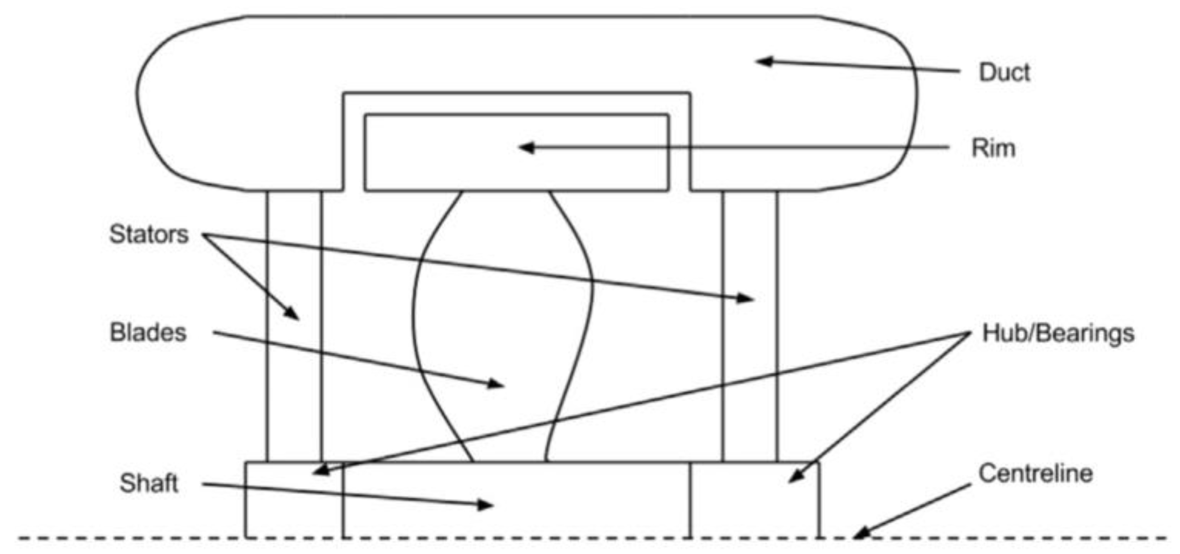
Hsieh et al. developed a hubless-type RDT with ball bearings embedded in the duct [
83]. Due to attrition in the bearings, the rotor was unable to achieve the specified speed at the rated voltage supply. Sharkh inserted bearings into the hub (on both extremities of the hub) to address this issue (
Figure 3), resulting in a reduction in both the friction resistance moment and friction loss [
56].
In a study, a bearing with a small proportional radius is used to modify the fan’s centerline axis configuration [
23]. The bearing is mounted on the stator body and rotates at the same speed. At the point of contact, the tangential speed of the fan and the bearing must be equal. This indicates that the rotational speed of the bearing is proportional to the ratio of the fan’s radius to the bearing’s radius. Therefore, a fan with a lower rotational speed requires bearings to rotate more, and this significantly higher rotational speed is responsible for a high noise band between 2 and 8 kHz. A slip bearing support was also used in this study. Current trends in acoustic research indicate that engine operation must be made silent by addressing bearing-related noise.
For micro autonomous underwater vehicles designed in MIT [
86], two options for bearings were considered: a long sleeve bearing and a pair of short sleeve bearings. The long sleeve bearing is built into the stator housing and placed between the stator poles and the rotor. It is smooth and in slide contact with the outer ring of the rotor. The rotor is slightly smaller to reduce mechanical friction. The long sleeve bearing can be made of Teflon or coated with it. The second option is a pair of short sleeve bearings placed at the front and back of the rotor like conventional motors. They have a radial component to prevent front and back movement and an axial component to maintain centeredness. They do not take up space in the air gap between the stator and rotor, allowing for better efficiency. A Teflon coating can also be applied to these bearings.
9. FEA and CFD
Rim-driven thrusters (RDTs) have been studied extensively using various numerical methodologies, including finite element analysis (FEA) and computational fluid dynamics (CFD). A number of factors have been explored to optimize RDT performance, including length diameter ratio, diffusion ratio, contraction ratio, tip diameter ratio, and blade size and shape. Additionally, researchers have investigated the impact of different RDT configurations, including hubless and hub-type designs.
Finite element analysis (FEA) and computational fluid dynamics (CFD) methods have been used in previous studies to analyze the performance of rim-driven thrusters (RDTs) [
57,
87].
A study by Song et al. employs a numerical methodology to investigate the influence factors of the rim-driven propeller. The hydrodynamic performance is scrutinized in a stepwise manner by analyzing the impact of the length diameter ratio, diffusion ratio, contraction ratio, and tip diameter ratio, utilizing the concept of sensitivity analysis [
88].
A rotor parametric model comprising of blades and a rim has been formulated. The model incorporates a range of variables that have been subjected to multi-objective optimization using ModeFrontier (ESTECO). The optimization process involved measurement of selected parameters through CFD simulations conducted with the Star-CCM+ solver (SIEMENS) [
89]. In a similar study, based on the findings, it can be inferred that with a marginal enhancement in the propulsion efficiency as compared to the initial blade, the optimized blade has the potential to augment the RDT thrust coefficient by approximately 15% [
90].
Freeman and Marshall analyzed a 280 mm diameter RDT using FEA and CFD to study the natural frequency and mode shape, flow paths, blade surface pressure, and thrust [
91]. Andersen developed a rim-driven water-jet pump and used a simplified steady-state computational fluid dynamics model to investigate the impact of hub-type and hubless guiding vanes on the overall efficiency of the impeller [
92]. The impeller efficiency of pumps with hubless guiding vanes was reduced by roughly 10 percentage points as a result of energy losses that occurred in the center line.
The CFD simulation method was applied to design a rim-driven thruster and a comparison between the calculated and experimental results of NO. 19A + Ka4−70 ducted propeller was conducted [
93]. As a result, the numerical method was verified and the improved Ka-series propeller was introduced and implemented. Finally, the study analyzed the effects of the propeller’s hydrodynamic performance as regards the number of blades, rake angle, and pitch. The hydrodynamic performance of the propeller is similar to that of the traditional ducted propeller and the absence of a hub improves cavitation and reduces noise. The rake angle does not have much impact on performance, but it should be determined based on the vibration of the tail. The propeller’s thrust, torque, and efficiency increase with the pitch, while the number of blades increases torque and thrust but decreases efficiency and cavitation performance. A lesser number of blades helps avoid cavitation, but it increases vibration.
The aerodynamic characteristics of the RDF were studied by investigating the effects of four key parameters, including the rotor disk height, number of blades, central hole radius, and blade root mounting angle [
94]. The research found that rotational speed greatly affects thrust performance, with performance improving as speed increases. Placing the rotor away from the duct entrance results in better aerodynamic performance. A larger number of blades increases peak thrust and ducted thrust performance but reduces the power load. Reducing the central hole radius decreases overall aerodynamic performance due to enhancing airflow blocking. Increasing the blade root mounting angle generates more thrust but reduces power load.
By investigating blade tip geometry modification, a study aimed to increase the strength of the centerline flow region to improve thrust performance in static fluid [
95]. The study utilized CFD for performance evaluation. Results showed that the reverse flow in the centerline, induced by the rotating blades from both the upstream ambient air and downstream domain, reduced overall thrust performance. Blade tip geometry modification was proposed to mitigate this issue, resulting in improved performance.
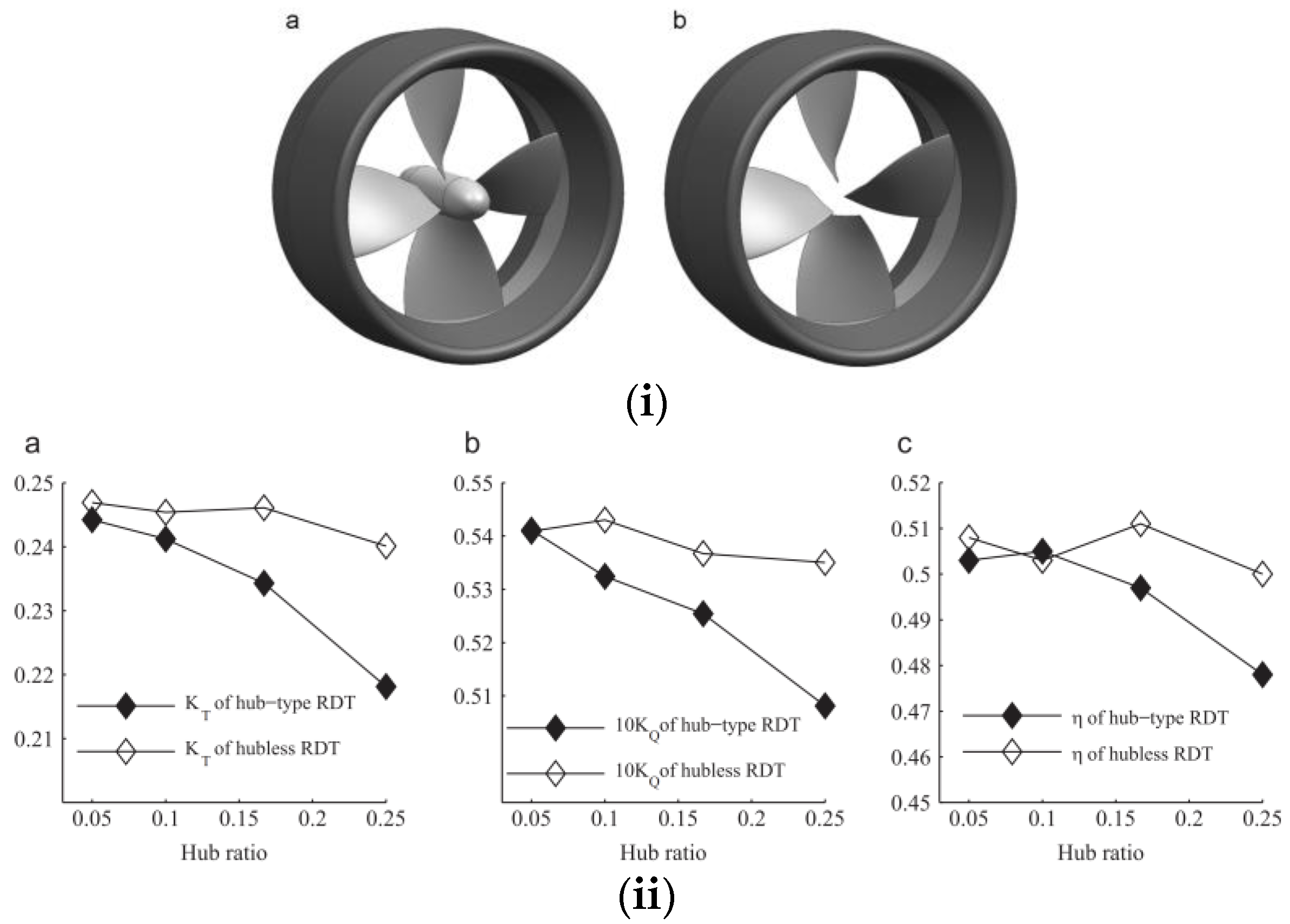
Yakovlev and colleagues designed RDT propellers both with and without hubs [
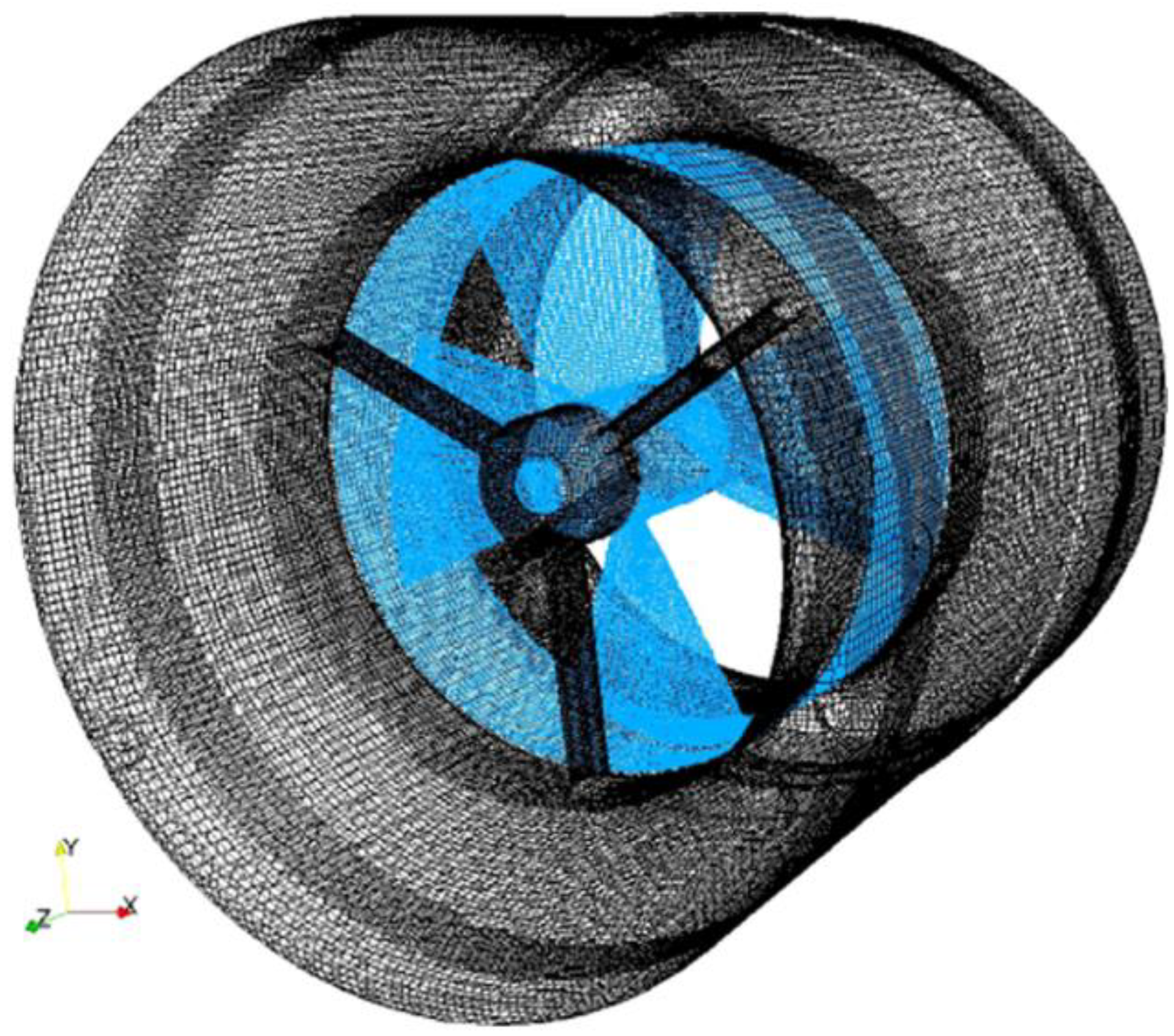
36]. While the efficiency profiles of these propellers were similar, the hubless variants generated higher levels of thrust and torque. This was primarily attributed to a slight reduction in the flow velocity over the propeller disk and the presence of larger blade radii in the hubless configuration. In open water, a CFD investigation by Song et al. [
96] determined that hub-type RDTs are less hydrodynamically efficient than hubless RDTs (
Figure 4). The hub restricted the water flow area, resulting in a faster axial water flow speed and a lower aft side water pressure compared to the RDT without a hub, which decreased the blade and duct thrust. Four pairs of four-bladed rim-driven thrusters having different hub ratios were tested to study the effect of the hub, where the hub ratio refers to the ratio of the hub diameter to the propeller diameter. The hydrodynamic performances of the hubless and hub-type RDTs are compared both at the design point and off-design points [
96]. Based on the computational results, it is concluded that the hubless RDT has a higher efficiency than the hub-type RDT. At the design point characterized by a hub ratio of 0.25 and an advance coefficient of 0.7, the efficiency of the hubless RDT surpasses that of the hub-type RDT by 2.2%. The absence of the hub also results in increased thrust and torque while reducing the thrust ratio (
Figure 4).
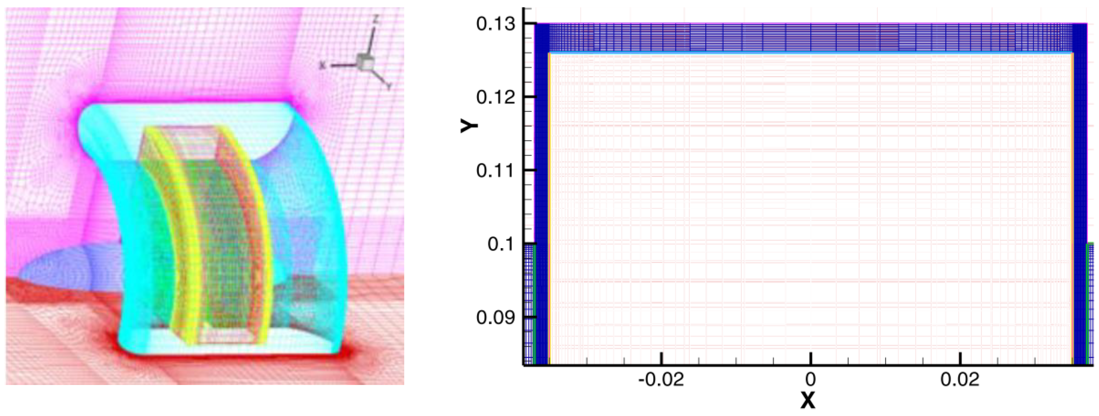
Cao et al. used a commercial RANS solver to investigate the effects of axial and radial gap flow on the torque of rim-driven thrusters [
97] (
Figure 5 and
Figure 6). Both simulation outcomes were robustly verified by experiments, demonstrating the simulation tools’ efficacy. The study analyzes the independent effects of axial and radial clearance ratios on the torque of the outer surface and end faces and presents a new predicted method by fitting the numerical and analytical results. The study reveals the presence of circular flow, Taylor vortices, and an increase in the torque coefficient with increasing radial gap clearance.
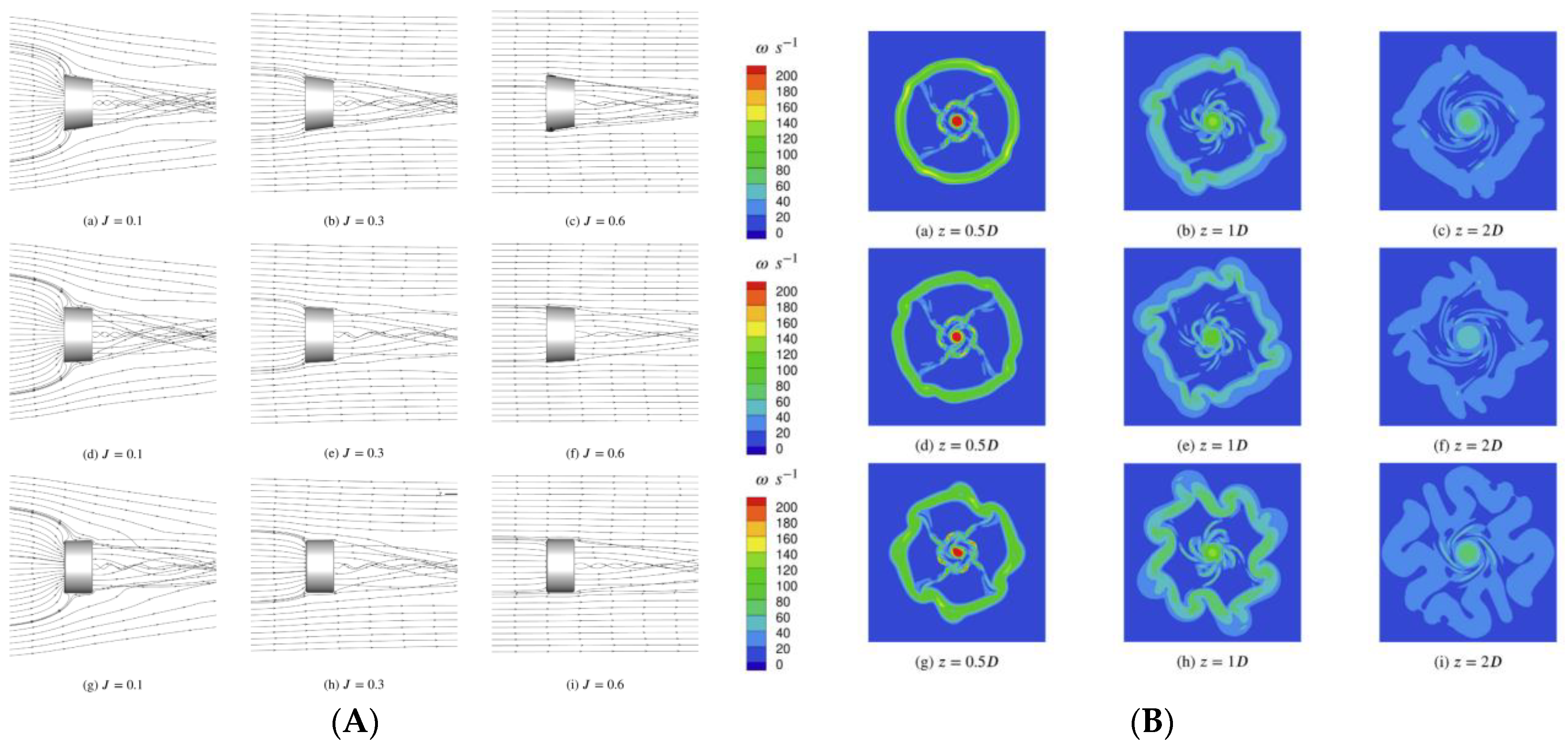
Dubas et al. provided a number of numerical solutions for assessing the hydrodynamic performance of RDTs across separate experiments conducted between 2011 and 2015 [
85,
98] (
Figure 7). The importance of considering the entire rotation of the device when using the frozen-rotor method to model rotor–stator interaction is highlighted. Under-predictions of torque and thrust were observed in the simulations, which were improved by the augmentation of analytical rim friction models. The lack of consideration for end effects which become significant at low aspect ratios and interactivity between axial and radial gap flows in the analytical models might explain the error in torque prediction. An unsteady simulation revealed an oscillating effect on the inflow angle to the blades caused by the rotor–stator interaction, which has design implications on pitch distribution selection. The oscillating flow past the stators causes an oscillating inflow to the blades, which may cause a variation in the effective angle of attack, implying potential peak loads.
The modeling approaches by Amri et al. demonstrated performance results that closely matched the experimental data, with deviations of less than 5% across a range of advance ratios when assessed using a Wageningen B4-70 propeller [
67].
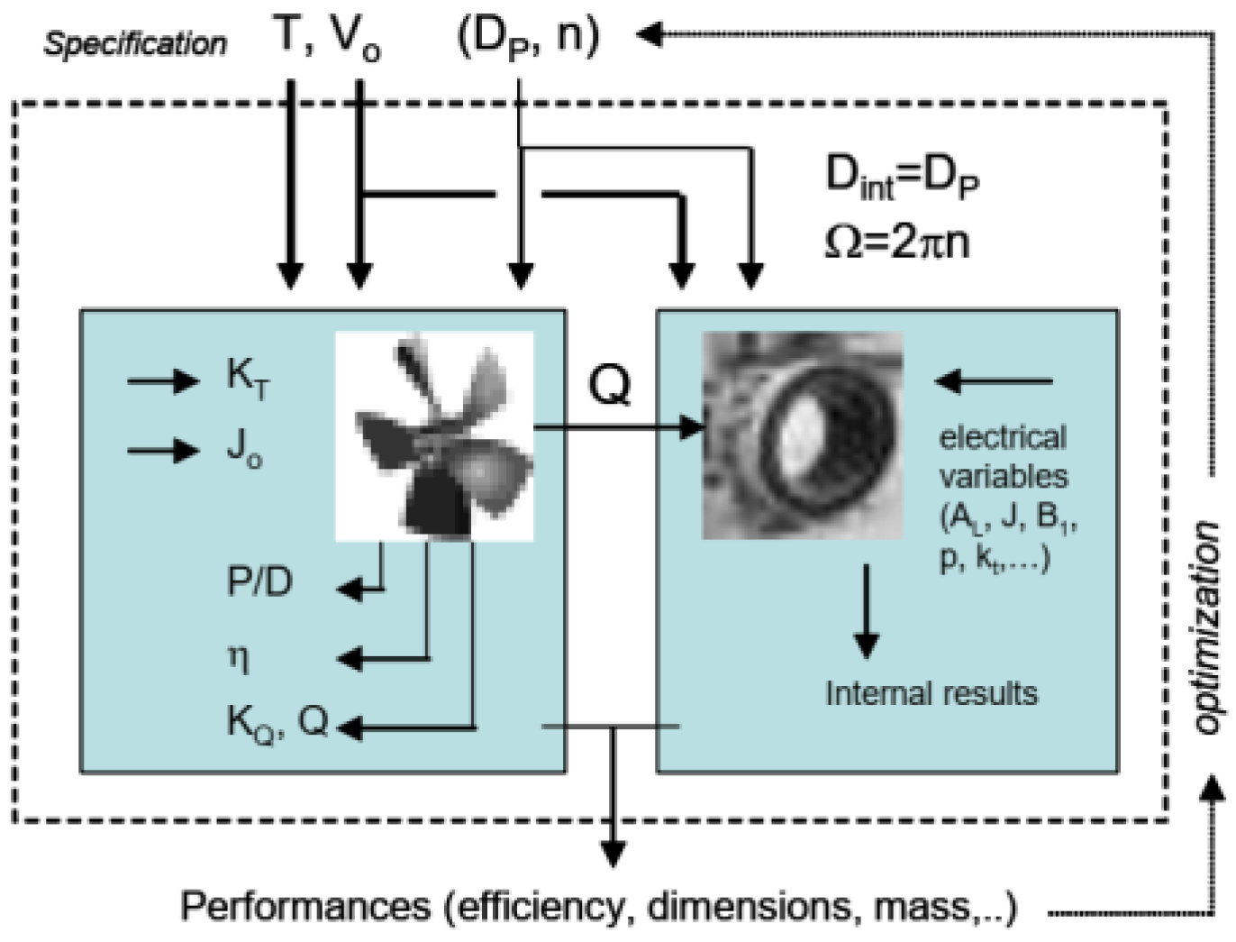
Drouen et al. (2008) discussed a model for designing a naval propulsion system that integrates electromagnetic and hydrodynamic factors [
99]. The model takes into account both the electromagnetic forces that drive the motor and the fluid dynamics that determine the thrust generated by the rotor (
Figure 8). The goal of the model is to optimize the system for maximum efficiency and reliability in marine environments. The article described the various components of the model and shows how it was used to design and test a prototype of the system.
Liu et al. delve into the prediction of hydrodynamic performance for a rim-driven thruster, considering different duct designs (as depicted in
Figure 9) and incorporating modeling for transition turbulence. The researchers conducted numerical simulations using a 3D unsteady Reynolds-averaged Navier–Stokes solver, and compared the results with experimental measurements. The study found that the inclusion of transition turbulence modeling significantly improved the prediction accuracy of thrust and torque coefficients for the rim-driven thruster. The results also showed that the duct design has an impact on the hydrodynamic performance of the thruster, with the presence of a stator blade enhancing the performance at low advance coefficients. Overall, the article highlights the importance of considering transition turbulence modeling in predicting the hydrodynamic performance of rim-driven thrusters, which can aid in their design and optimization for various applications [
100].
Gaggero present a simulation-based design optimization tool for rim-driven thrusters including a parametric description of blade geometry and a multi-objective algorithm driven by high-fidelity calculations [
26] (
Figure 10). The design process utilizes B-spline curves for blade geometry, RANS calculations, and a genetic algorithm. Four blade configurations are tested, and the optimized propellers outperform a benchmark ducted propeller. The number of blades does not significantly impact cavitation risk. Computational cost is a constraint, and exploring faster algorithms could enhance the design process. Overall, the tool proves effective in improving performance and minimizing cavitation in rim-driven thrusters. Faster calculation methods could enhance convergence.
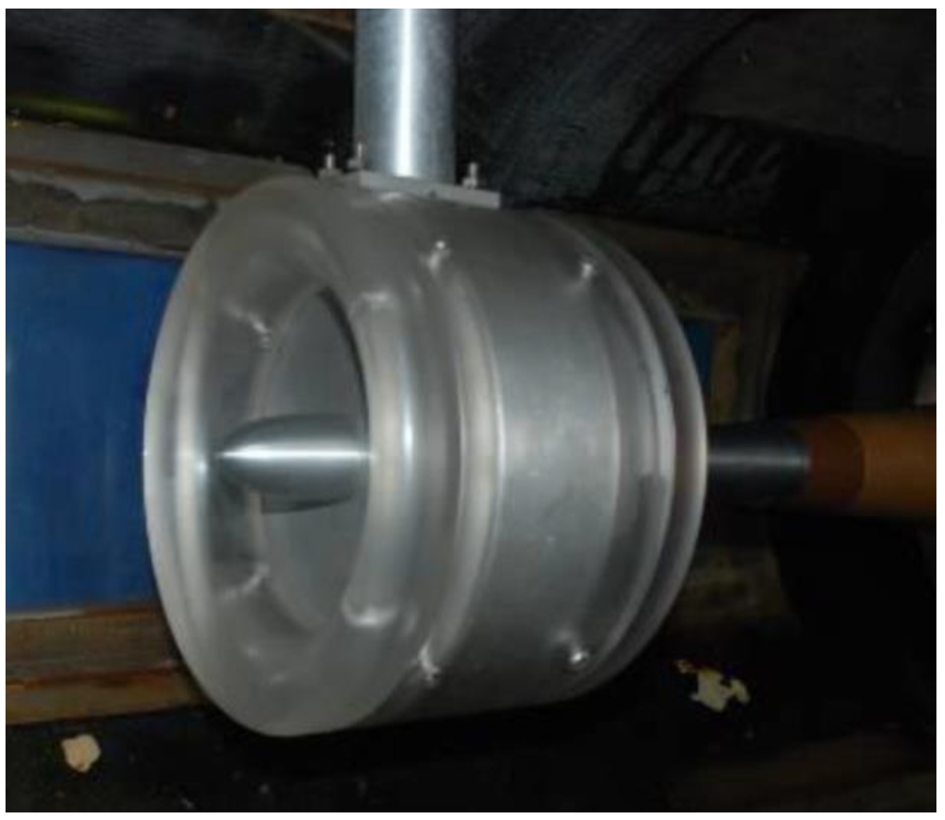
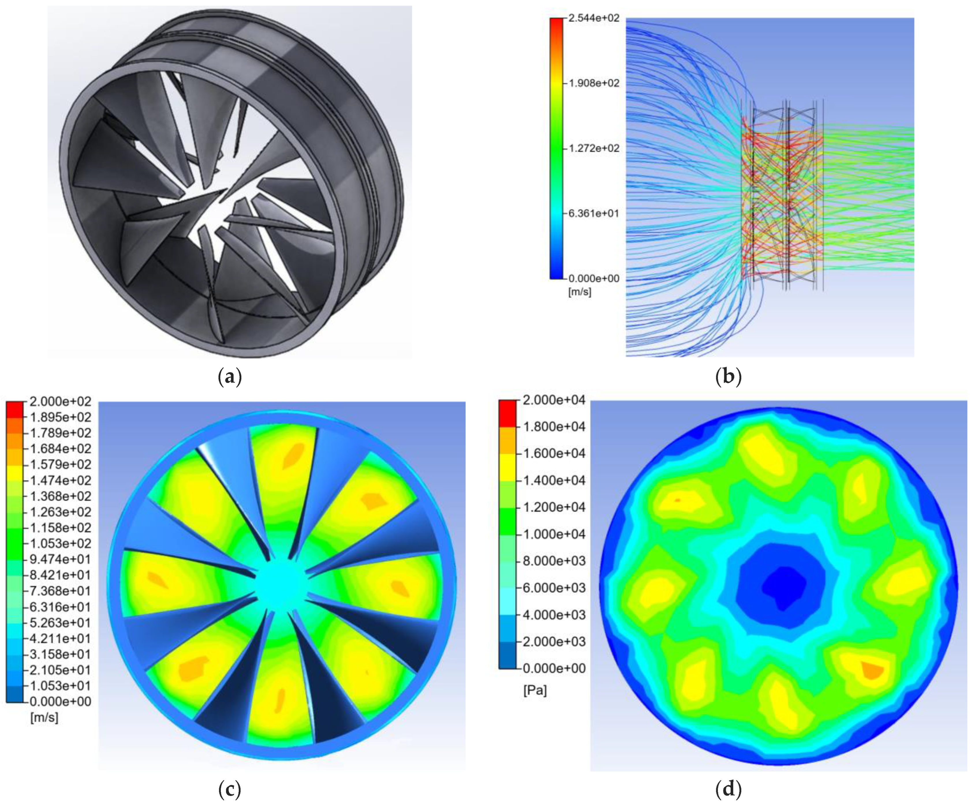
The study by Bolam et al. compared the performance of an RDF with an equivalently sized electric ducted fan (EDF) [
101]. The study discovered that the RDF configuration outperforms the EDF in terms of thrust, providing 212 N compared to the EDF’s 95 N, and achieving a higher RDF efflux velocity of 150 m/s (equivalent to 336 mph) as opposed to the EDF’s 103 m/s (230 mph). Researchers initially used a 2D pitch-line methodology to determine the initial fan blade shapes and velocity estimates. However, there was a significant discrepancy in the calculated thrust values between the 2D pitch-line methodology (317 N) and the CFD model (212 N). This difference was partly attributed to an overly optimistic assumption regarding the effective through-flow area of the hubless configuration in the 2D pitch-line approach. The CFD results showed that the RDF design effectively mitigated whirl but still exhibited some degree of swirl in the exhaust airflow. The design offers substantial potential benefits for general aerospace applications and can yield even greater advantages when it is scaled up to much larger and more powerful RDF propulsion units (
Figure 11).
Researchers have extensively discussed and offered valuable recommendations for improvement in various aspects of rim-driven thrusters (RDTs), including hydrodynamics, propeller design, motor design, and driver design. These insights can be highly relevant and beneficial in the application of RDTs and RDFs. Additionally, RDTs have demonstrated their effectiveness in various other contexts, further emphasizing their potential usefulness and applicability in aerial propulsion applications. The
Table 1. briefly summarizes relevant works related to aerial applications, citing articles referenced in this manuscript.
10. The Future Prospects of Rim-Driven Fans
The future prospects of rim-driven fans (RDFs) hold great promise and potential for various industries, particularly in the aerospace and maritime sectors. In recent years, the maritime sector has witnessed the emergence of the shaftless rim-driven thruster (RDT) as a groundbreaking ship propulsion option, marking a significant step towards more efficient and eco-friendly vessel propulsion. With advancements in electrical rim drives and the commercial availability of RDT devices for both surface and underwater vessels, the maritime industry has already reaped the benefits of this innovative technology. Looking ahead, we can anticipate a continued growth in the adoption of RDTs in the maritime domain. The application of RDFs is not limited to marine transport; there is also great potential for their integration into automotive and aerospace sectors, albeit with some lag in development. As the cost of larger base forms, advancements in technology, and the necessary technical expertise become more accessible, RDFs are likely to play a more prominent role in these sectors. The utilization of electromagnetic–thermal–fluid–solid coupling in high-power RDFs, as evidenced in recent theoretical and experimental studies, further underscores the potential for more efficient and effective RDF designs in the future. These studies shed light on the intricate interplay between electromagnetics, fluid mechanics, structural dynamics, and thermodynamics in RDFs, paving the way for advanced and highly optimized RDF technology.
In the aerospace sector, the future prospects of rim-driven fans also present exciting possibilities. As technology continues to evolve, the development of RDFs for aerospace applications is expected to gain momentum. The efficient and compact nature of RDFs can offer significant advantages in terms of propulsion systems for aircraft, drones, and other aerospace vehicles. Their potential to reduce noise and enhance efficiency is particularly appealing for the aviation industry, where environmental concerns and operational cost savings are of paramount importance. As research and development efforts in RDF technology continue to progress, we can anticipate more widespread adoption of RDFs in aerospace applications, resulting in quieter, more energy-efficient, and environmentally friendly aircraft.
11. Summary
In conclusion, rim-driven thrusters (RDTs) have been the subject of theoretical and practical studies that have led to significant developments and practical applications in both the marine and aerial sectors. Along with reviewing the development of rim-driven fans (RDF), this paper has provided an update on recent RDT studies and discussed electric motor, bearing construction, and aerodynamic and hydrodynamic optimization, making the design, performance analysis, and control of RDTs more efficient and effective. When compared to standard shaft-driven thrusters, RDTs offer several benefits, including a compact design, improved motor efficiency, higher aerodynamic efficiency, reduced demand for secondary systems, and the possibility to produce an undetectable RDF jet. All this suggests that RDTs could offer a more sustainable and efficient alternative to conventional thrusters, especially in environments where high maneuverability, low acoustic noise, and low detectability are essential.


