1. Introduction
The evolution of aircraft structural components has prioritized safety and economic efficiency. Yet, there has been a lack of emphasis on visualization and simulation in published works on designing aircraft nodes [
1]. In today’s world, it is essential to comprehend and interpret information quickly. Visualization is crucial in achieving this by bringing new information closer, making abstract concepts more tangible, highlighting the main focus of the topic and problem, and, in some cases, simplifying the mathematical models of phenomena [
2,
3,
4].
Computer-aided technologies are experiencing a surge in demand due to the need for development and adaptation in today’s market [
5]. Computer-aided technologies, unified under the general term CAx, where x represents various processes in the product lifecycle, present numerous possibilities on how to streamline processes in a broad spectrum of industries. The most used terms associated with CAx are computer-aided design (CAD), computer-aided manufacturing (CAM), and computer-aided engineering (CAE). The use of visualizations and simulations in various industries is driving continuous progress in CAx systems. For a better understanding of the possibilities of CAx software solutions, refer to the comparison of the most used CAx software solutions,
Appendix A,
Table A1. The aviation industry, known for its focus on innovation, efficiency, and safety, is a prime example of the benefits of CAx systems [
6,
7]. By utilizing these systems, designers can significantly reduce the time it takes to design individual components. Additionally, simulations can detect deficiencies or malfunctions in structural units, allowing for quick resolution of any issues [
8].
Based on its recent progress, the future of CAx systems looks bright [
9]. In recent years, there has been significant growth in the use of these systems, even in 3D modeling and mechanical design. To keep up with the market’s demands, current CAx software needs to be faster, simpler, and more user-friendly. Over the last decade, not only have design tools improved, but CAx systems have also become more complex [
10,
11,
12]. As a result, using CAx systems can speed up the design process and provide suggestions while also identifying potential design issues. The origin of CAx programs can be traced back to the late 1960s and early 1970s when major aviation, automotive, and electrical engineering companies were seeking new ways to develop, construct, and produce products to secure their market positions. Companies such as Boeing, Douglas Aircraft, Renault, General Motors, and Ford recognized the necessity of computers, although the concept of CAx programs and computers at that time was vastly different from today’s situation. Mainframe computers were standard equipment for companies, but their exorbitant prices were not feasible for the time. Home computers were practically non-existent [
13,
14].
Initially, the first CAx systems were primarily developed for internal company use and not for resale. It was only later, with the rapid development and wider availability of computers, that companies began to emerge whose primary business was creating custom programs for repeated sales [
15]. These programs eventually found their way into almost all industries, significantly improving efficiency. When evaluating project strategies, it is essential to consider the following factors:
The method of dividing projects into sub-tasks.
Strategies of the sequence of partial solutions and mutual relations.
Techniques for generating project ideas, evaluating solutions, and processing information.
Designing a project-solution strategy for specific implementation conditions is a complex and often ambiguous process [
16,
17,
18]. According to surveys, cyclical and branching strategies are the most commonly used methods when creating complex systems. Additionally, there are special approaches geared towards innovative systems like CIM, flexible production, robotic production, and customer-oriented production, just to name a few, that are currently being developed. Modern methodological aspects of design show the most progress from a computer support standpoint. One such approach, CIM-OSA, can be considered a reformation tactic for scientific design methods [
19].
Another area of development in engineering design is the integration of knowledge engineering. In the United States, companies like Intel Corporation, Technowlidge, and Inference Corp. are utilizing these new technologies in commercial practice. Expert systems represent knowledge engineering and differ from classic program systems in multiple ways [
20]. The effort to generalize partial design methodologies and connect them to computer support is reflected in the design theory. However, the object and functions of design theory are not completely unified in the professional literature. Some authors consider design as an integral part of the overall system, while others prefer the concept of design philosophy or methodology [
21]. Ultimately, five basic schools of design methodology development can be defined, including semantic, syntactic, historical, psychological, and philosophical schools.
Inspections in the mechanical and aviation fields have seen a transformative shift with the integration of robotic sensors. These sensors, equipped with advanced technologies such as LiDAR, ultrasonic sensors, and thermal imaging, play a crucial role in enhancing inspection processes. In the aviation sector, for instance, robotic sensors are increasingly employed for Non-Destructive Testing (NDT) of aircraft components. This includes the inspection of critical structures and components for potential defects or wear [
22]. The use of robotic sensors not only improves the efficiency of inspections but also enhances safety by minimizing human involvement in high-risk areas. In the broader mechanical field, industries are adopting robotic inspection systems for quality control, preventive maintenance, and monitoring of complex machinery. The data collected by these sensors facilitate predictive maintenance, reducing downtime and overall operational costs. As technology continues to advance, the integration of robotic sensors in inspections is expected to become even more sophisticated, contributing to improved reliability and safety across various industrial sectors.
The significance of data acquired by robotic sensors in the context of inspections in the mechanical and aviation fields cannot be overstated, particularly in the realm of predictive maintenance. The real-time information collected by these sensors enables the identification of potential issues before they escalate into critical failures. In aviation, for example, continuous monitoring through sensors allows for the early detection of structural weaknesses or anomalies in aircraft components, contributing to proactive maintenance strategies. Similarly, in mechanical systems, the data acquired from robotic sensors are instrumental in predicting equipment failure and scheduling maintenance interventions. This predictive approach not only minimizes the risk of unexpected breakdowns but also optimizes resource utilization and prolongs the lifespan of machinery. The ability to harness and analyze data from these sensors is a milestone of modern maintenance practices, fostering a more efficient and cost-effective operational environment [
23].
In the majority of the presented methodologies, design is approached with significant computer support, and the use of computers is prevalent. While computer presentation may not be utilized in all stages of the designing process, it is not excluded either. The objective is to create “intelligent computer systems for designing”. Simultaneous engineering is considered a crucial technique for innovation preparation in design, allowing for a radical reduction in development and implementation time. The principle of SI (Simultaneous Engineering) is built on overlapping stages of new product creation, including specification, design, construction, prototyping, testing, and preparation for serial production [
24]. Unlike the traditional approach to development work, the application of simultaneous engineering demands rigorous conditions, such as the application of effective testing techniques, the elimination of erroneous trials, the separation of solution experiments from confirmatory trials, concentration on critical areas, and the utilization of simulations. Simultaneous engineering also includes Rapid Prototyping methods using 3D models of objects as input information for dividing their volumes into layers and subsequently creating and connecting individual layers into a physical model [
25].
2. Materials and Methods
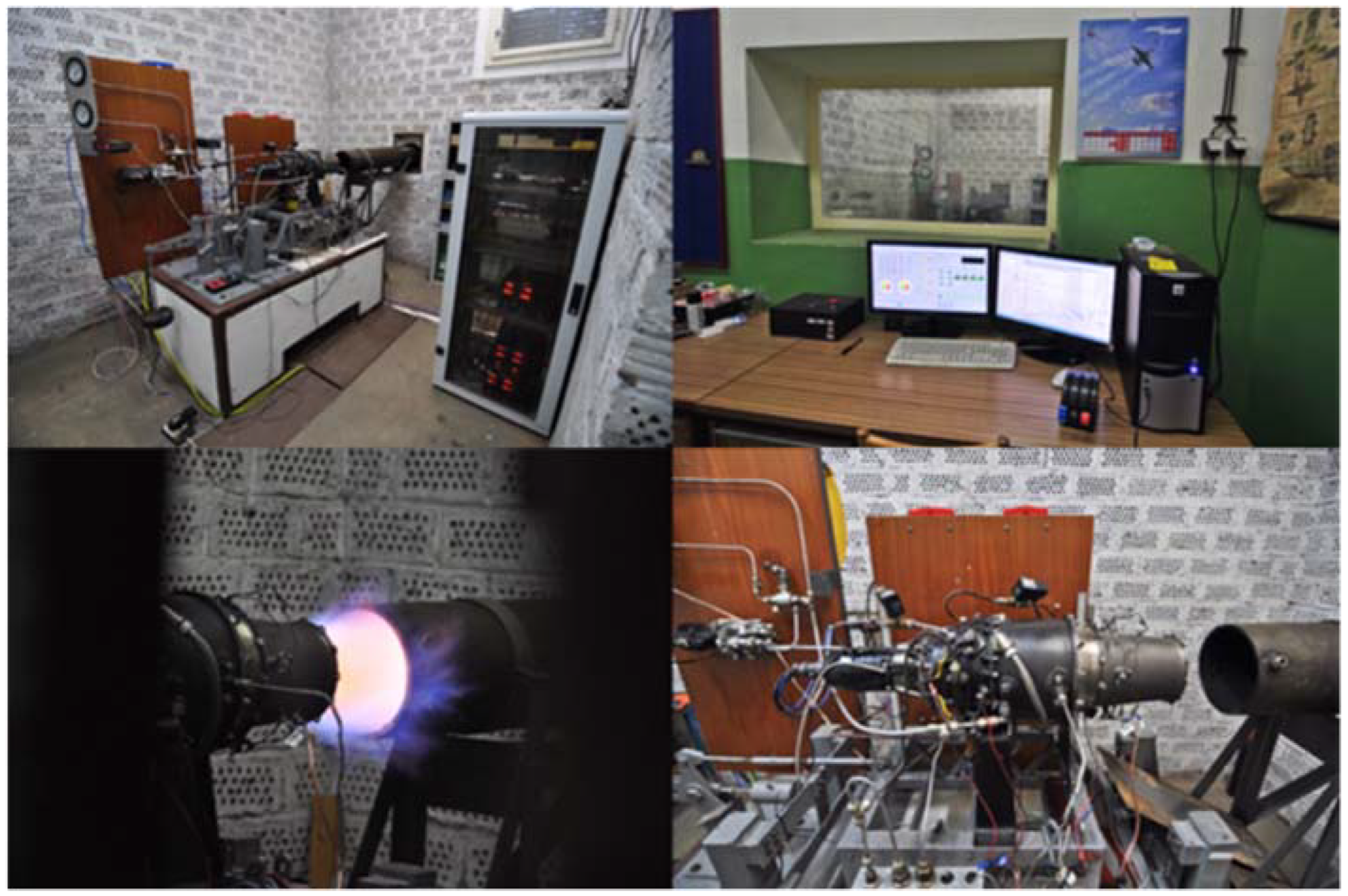
To remain competitive, manufacturers are increasingly utilizing CAx systems, such as CAD, to enhance their products. However, it is important to note that neglecting follow-up parts oriented to support CAM systems can hinder the effectiveness of these high-end tools. CAx system manufacturers must also keep up with market developments and continuously improve their software to better meet customer requirements and maintain their position in the market. This trend is expected to continue. The choice of the engine construction node for the creation of visualization and simulation using CAx systems was mainly influenced by an interview with members of the Faculty of Aeronautics, Technical University in Košice. The Department of Aeronautical Engineering deals mainly with the development of controls for small jet engines. So far, the department has performed all its experiments on a small jet engine, MPM-20, which is located in the laboratory of intelligent control systems of aircraft engines at the Faculty of Aeronautics (
Figure 1). As part of the scientific research activity, the laboratory mainly deals with issues of management, diagnostics, safety, efficiency, and reliability of the small jet engine, MPM-20. Various methods and approaches from practice are used to perform experiments—in particular, situation management, artificial intelligence approaches, neural networks, fuzzy systems, expert systems, methods of statistical analysis, probabilistic calculations, and other mathematical methods and models. Based on the requirements of the department and the laboratory of intelligent aircraft engine control systems, it was necessary to create a 3D model of the MPM-20 engine to simplify and streamline current and future experiments.
For the digitalization of individual components, CATIA V5 was used as the software basis. CATIA is a 3D design system that can help accelerate the development process of mechanical engineering products. It offers a wide range of solutions that can provide a stable and comprehensive development environment, from design to production. The software provides users with the ability to record and reuse know-how, which drives the implementation of best business practices. The CATIA V5 system comprises three distinct platform configurations, denoted by P1, P2, and P3. These platforms are designed to offer varying options and levels of complexity in terms of available tools. Ascending the platform hierarchy, the range of available options and the sophistication of accompanying tools increase in parallel.
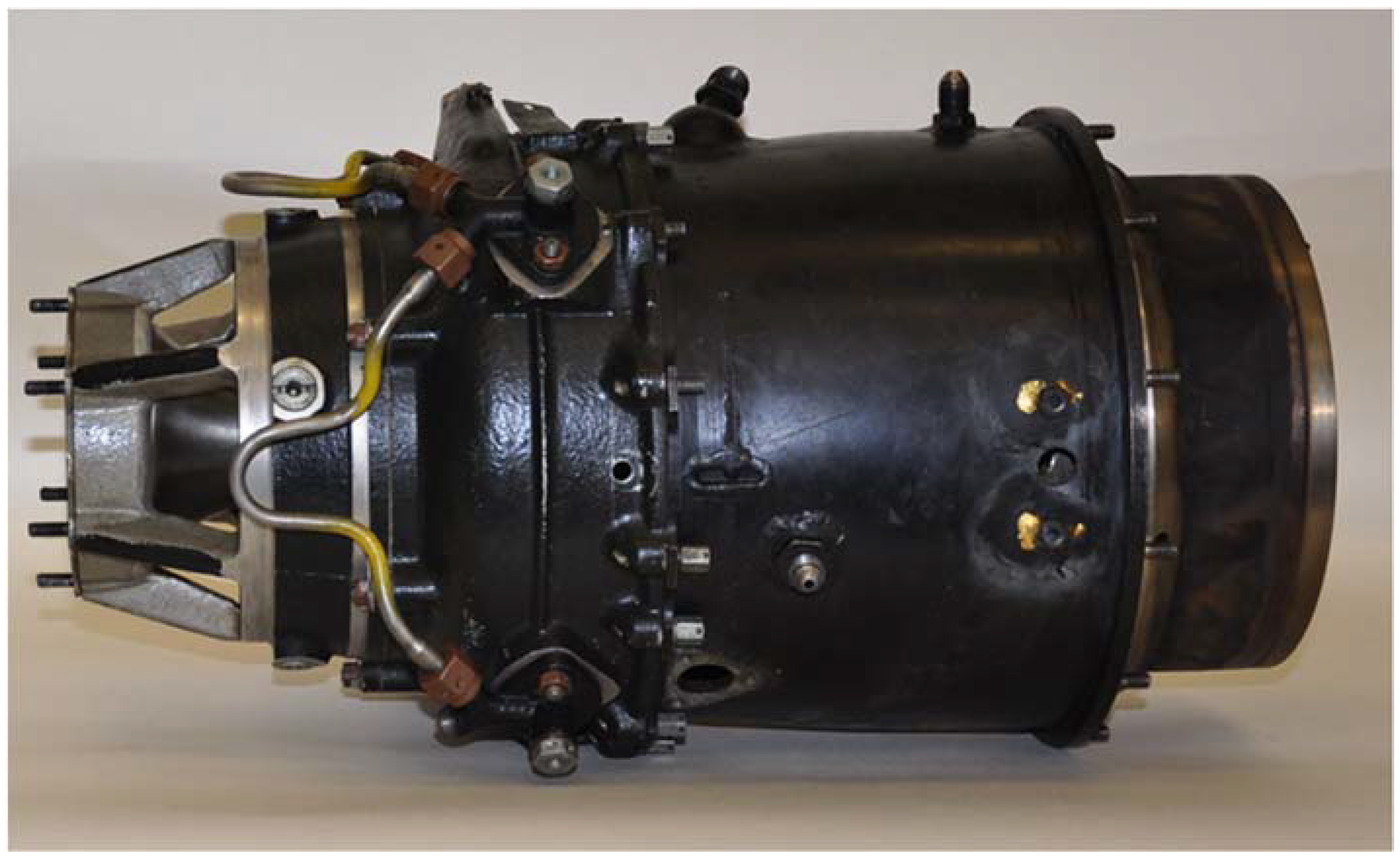
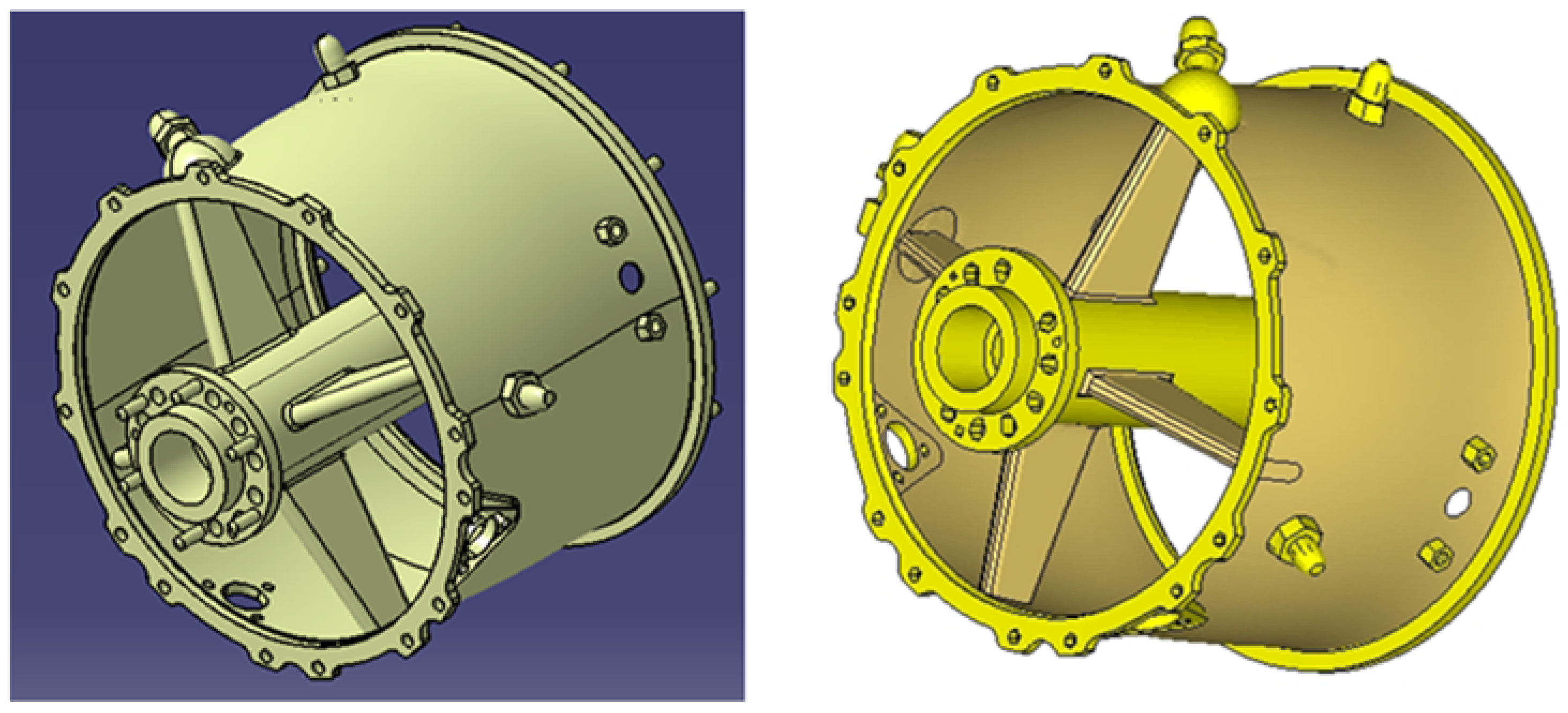
The small jet engine, “MPM-20” (
Figure 2), is a small, single-jet, single-shaft aircraft turbo-compressor engine, which was created by modifying the turbine launcher “TS-20B” for the needs of experimental measurements in the aircraft engine test room of the Aviation Faculty in Košice. The “MPM-20” small jet engine has a single-stage radial compressor with a single-sided impeller, a combined combustion chamber, a single-stage axial non-cooled reaction-type gas turbine, and an exit system with a fixed exit nozzle. The “MPM-20” engine has a separate fuel-regulating system, oil system, and electric starting system.
The small jet engine “MPM-20” consists of the following structural elements (
Figure 3):
Engine inlet (1).
Radial compressor cabinet (2).
Radial compressor (3).
Paddle diffuser (4).
Combustion chamber cabinet (5).
Combustion chamber (6).
Stator ring of a gas turbine (7).
Gas turbine rotor disk with rotor blades (8).
Gas turbine casing (9).
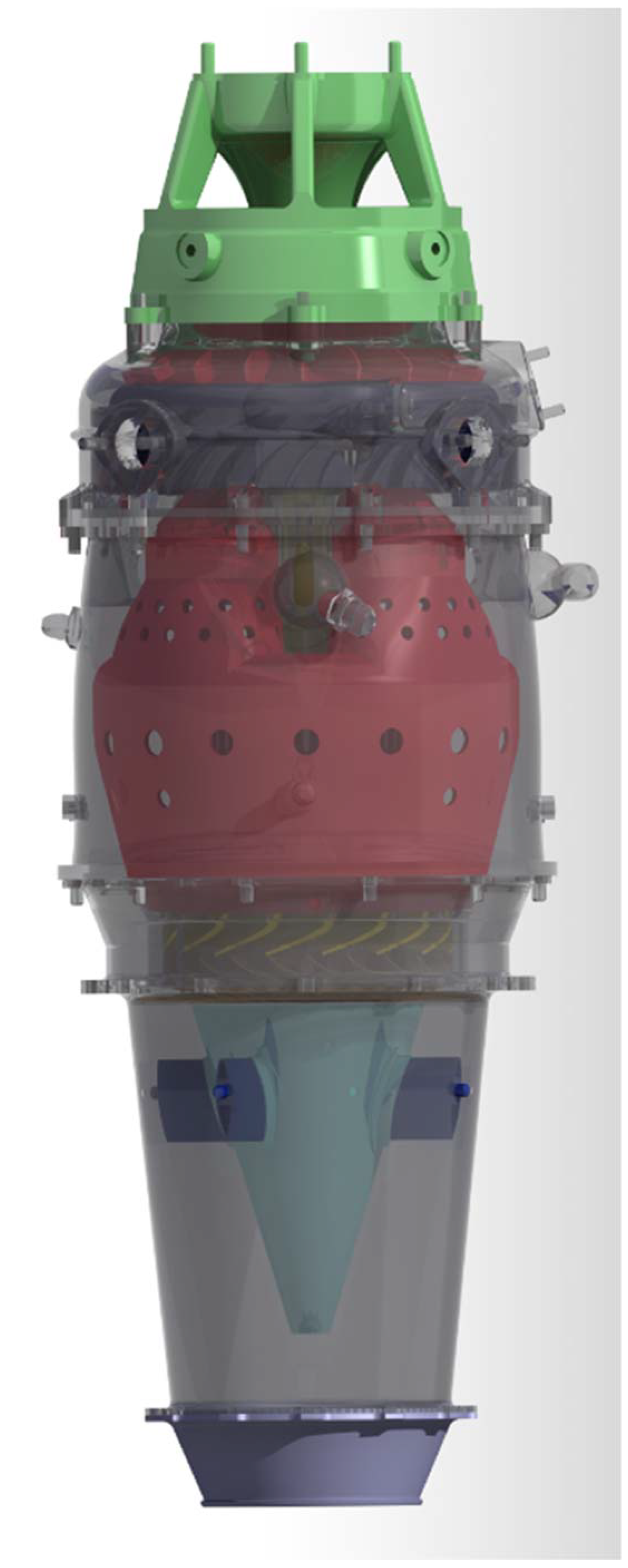
For a possible comparison of real components with visualization of the disassembled MPM-20 jet engine, refer to
Appendix B,
Figure A1. The hand-held 3D scanner EXAscan (
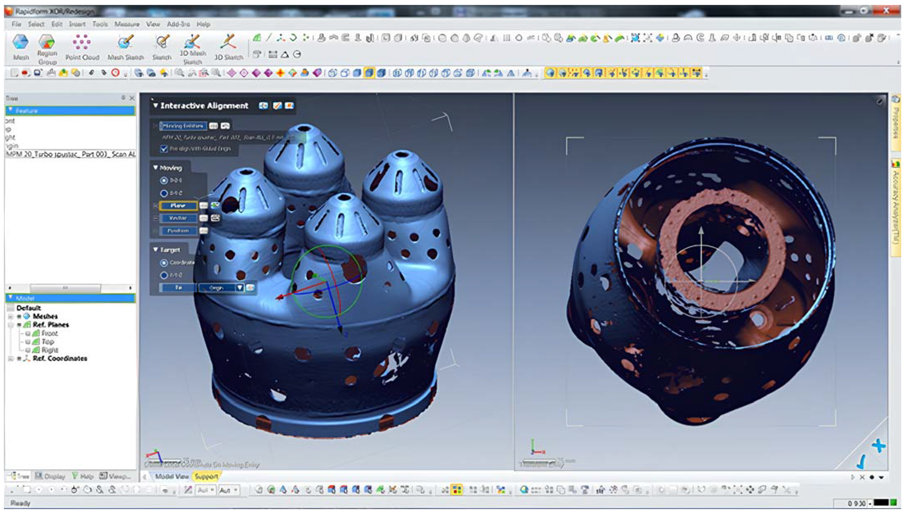
Figure 4), which was lent by the company CEIT-KE s.r.o., was used to digitize these components. This hand-held laser scanner allows the quick creation of a 3D CAD model based on a physical object. EXAScan scans have detailed resolution in individual x, y, and z axes (0.05 mm) and high volumetric accuracy (20 µm + 0.1 L/1000) while directly creating a polygon network with the option of saving in the standard format *. STL, modeling in CAD systems.
The scanning process itself is carried out with the support of the Vxelements system, which is supplied together as software for the collection and subsequent editing of scanned data from the hand-held 3D scanner EXAscan. This software consists of three separate modules: Vxscan, Vxprobe, and Vxtrack. It is used by all Creaform scanning devices. The program ensures communication between the computer and the scanner during the actual scanning. The Vxelements working environment can be evaluated as favorable even for a designer with basic user experience. The program includes the option to save the scanned object in *.STL format. This is important for further processing in CAx software, as not all programs allow saving in this format.
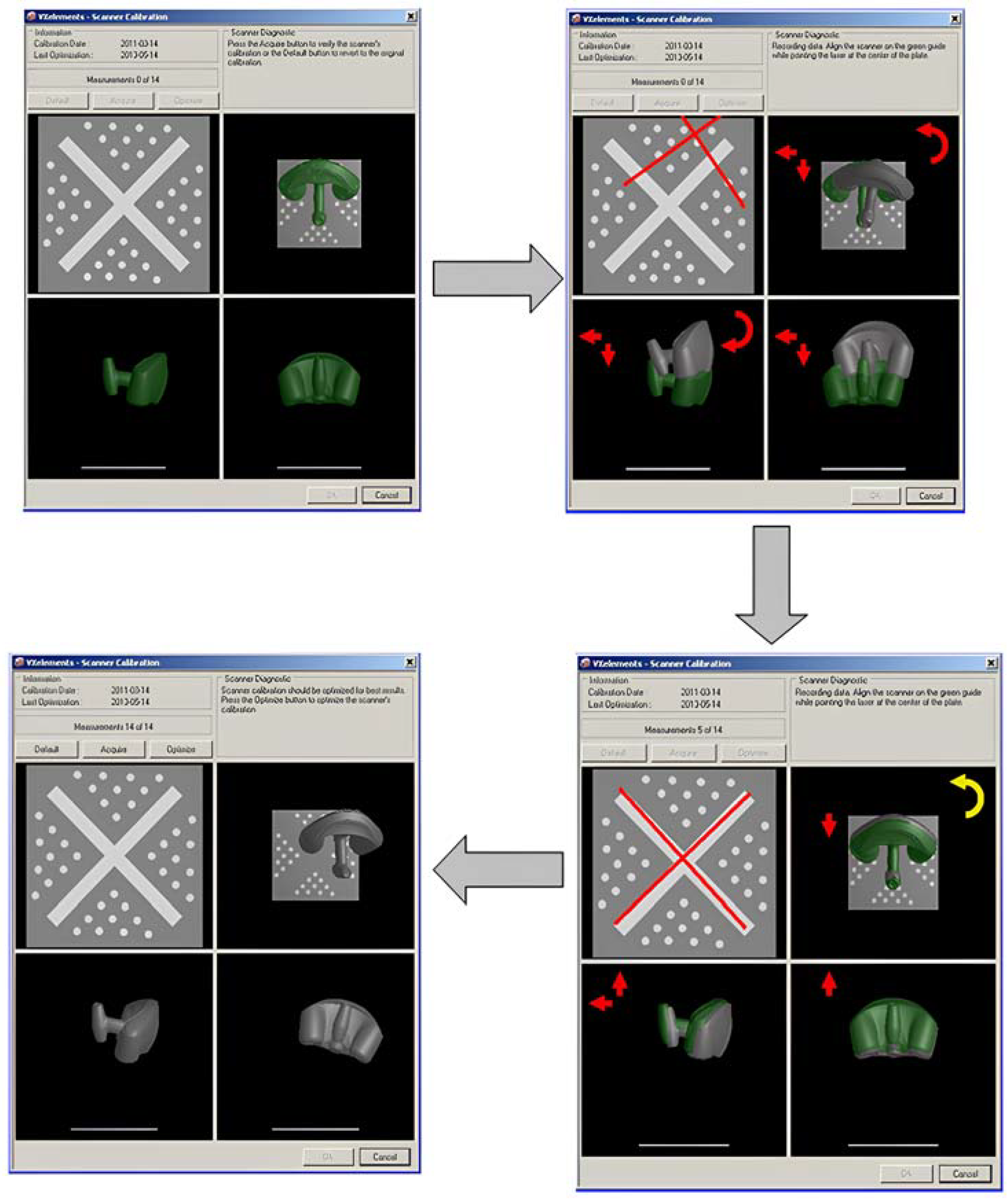
Before the process of scanning the selected element begins, it is necessary to calibrate and configure the scanner (
Figure 5). Calibration is performed using a calibration plate. Matching serial numbers between the scanner and its unique calibration plate is of utmost importance. Any mismatch may result in inaccuracies in the 3D scanning process. Therefore, it is necessary that the second EXAscan 3D laser handheld scanner is paired only with its corresponding calibration plate bearing the same serial number. To ensure proper and accurate scanning of an object, it is necessary to use position markers that come with the scanner.
The utilization of a 3D scanner involves the intricate movements of the device around the designated object, resulting in the generation of an accurate and precise 3D model in just a matter of minutes. The 3D-scanned model is an accurate representation of the original object. It can be further analyzed and processed using compatible software. This modern technology has revolutionized the field of product design and manufacturing, enabling unprecedented levels of detail and accuracy in the replication of physical objects. If the recording fails, the correction will be performed by rescanning.
3. Results
Simulations and various types of analyses are currently part of modern Cax systems. The importance of 3D models is primarily confirmed during the pre-production stage of concept creation or experimental testing, where various production options and methods can be verified on individual 3D parts or the entire virtual assembly. Based on the visualization of the proposed procedures, the weak points can be relatively quickly evaluated and subsequently eliminated without the need for significant interventions. Cost savings can be achieved through the use of 3D models in these stages of the production process.
The finite element method (FEM) will be used to simulate the development of stresses caused by thermal expansion of the combustion chamber shell. In practice, the FEM method is frequently used to simulate stress curves, heat flow, fluids, and deformations of the selected construction component or created set of parts. The main idea is to use finite nodal points to replace the continuous volume of the model. Individual node points represent the detected parameters of the component. The mentioned method can be used to determine the critical zones of the component or to check the designed parts.
Thermal analysis deals with the effect of heat flows and thermal fields on the mechanical properties of selected structural elements. One of the main aspects of the calculation is dilation and thermal stress, either at the level of the selected part or the entire assembly. It is imperative to note that the computation of steady heat flow or transient heat flow accompanied by time-varying boundary conditions is of utmost significance in various domains. These analyses are particularly useful in instances where internal stresses and deformations arise in the casting or mold.
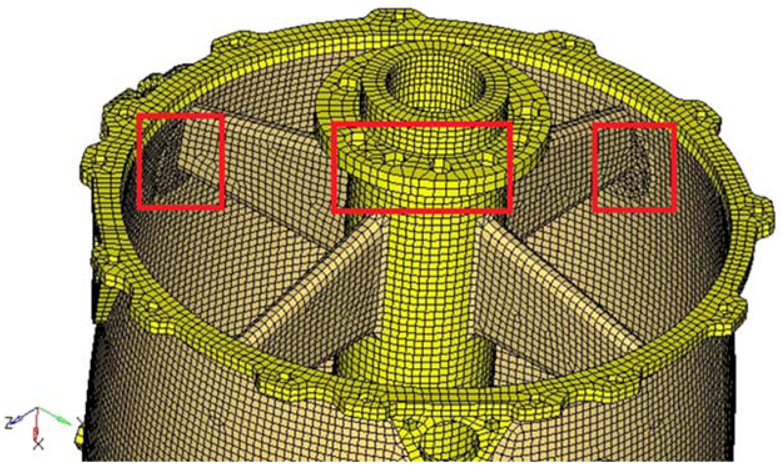
The analysis of the selected structural element was performed utilizing the CAx HyperMesh 10 system. Based on the creation of a 3D model of the combustion chamber shell in the Rapidform XOR environment, the geometry of the entire batch can be continuously transferred to the HyperMesh working environment (
Figure 6). It is also possible to use other simulation systems to evaluate the designed structural element due to the possibility of exporting the entire batch to *.IGS and *.STP formats. Before the actual transformation of the selected CAD model, it is advisable to modify this model to simplify tasks, shorten the length of the solution, etc. The methods of simplifying the CAD model include the suppression of geometry elements, geometry cleaning, and geometry idealization.
The mesh of the selected group is generated by subdividing it into a finite number of small elements. The finer the subdivision, the more detailed the description of the actual structural component. When a mesh is established on the investigated part, the process involves the generation of nodes and elements. This operation is carried out through systems known as mesh generators. In contemporary FEM software, the creation of a mesh on the construction part can be automated. The advantage of automatic mesh creation lies in being liberated from the arduous task of manually adapting the mesh to the part’s geometry. However, the drawback of employing this tool is the absence of direct control over the mesh creation process in the area of interest. This also encompasses the method of free meshing. The utilization of this mesh generation method is applicable to geometrically irregular shapes. The generation of a mesh through this method is straightforward and expeditious, albeit the ensuing calculations entail a considerable amount of time, given the creation of a substantial number of elements. Another method is denoted as mapped meshing. In terms of computational efficiency, this method proves to be faster due to the reduced number of elements on the structural component, but this method is incapable of generating meshes on geometrically irregular shapes.
In formulating the mesh for the combustion chamber cabinet, both methods of mesh generation were employed, guided by the optimal balance between computation time and the intricacy of the resultant mesh. Upon the translation of the 3D parametric model equivalent into the HyperMesh working environment, the mesh for the engine was generated through distinct mesh generation methods treated as a unified volume. To ensure the continuity of interconnections among elements generated through diverse methods, it is imperative, during the mesh generation and design process, to adopt a methodology that facilitates the feasibility and viability of these connections. The generated mesh must represent a modeled structural element (
Figure 7). Derived from this, the volume of the engine casing mesh has been partitioned into finite elements delineated through mapped meshing, with these being distinct from elements employing the free meshing method. The determination of boundary conditions involves the imposition of loads and appropriate ties, therefore ensuring that the model of the combustion chamber cabinet assumes a defined spatial orientation. These conditions can be applied to surfaces and edges.
Through the utilization of system tools, the links were defined, facilitating the restriction of movement in the designated direction within the global coordinate system. In pursuit of verisimilitude in simulating the load response of the chosen construction element during the combustion process, constraints were imposed on movement along the x-axis and rotation around the x, y, and z-axes while allowing unrestrained links along the y and z axes. Material properties consistent with those of highly alloyed steels were imparted to the model.
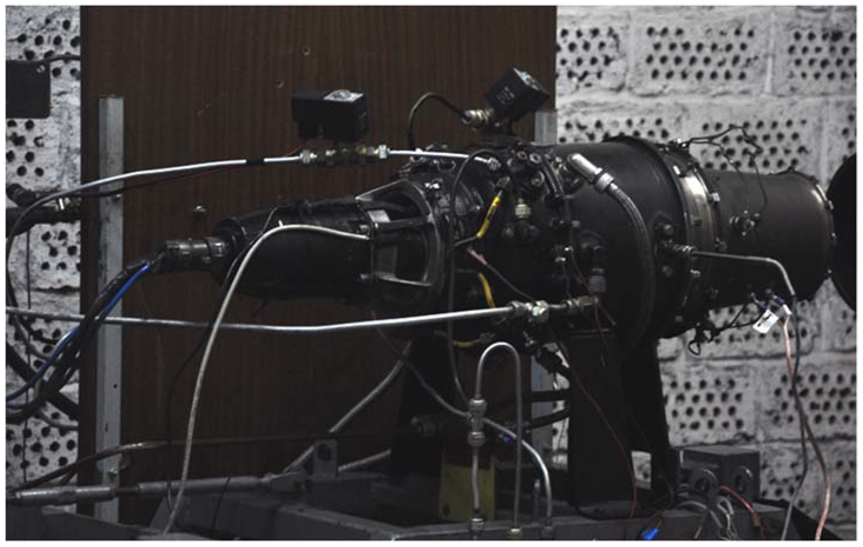
To record the temperature of the combustion chamber cabinet, a camera with a temperature range corresponding to the expected surface temperatures of the engine is required. In the research conducted, the FLIR A40 thermal imaging camera will be employed. This camera is equipped with a detector (Focal Plane Array System, microbolometer field) featuring a resolution of 320 × 240 points and operates within a spectral wavelength range of 7.5 to 13 µm. Thermal imaging measurements can be conducted with a sensitivity of 0.08 °C and an accuracy of ±2 °C. The test object, a small jet engine, MPM-20, shown in
Figure 8, is located at the laboratory of intelligent aircraft control systems, Faculty of Aeronautics, TUKE. All thermal stress tests performed on this real object took place in laboratory conditions under the supervision of experienced researchers.
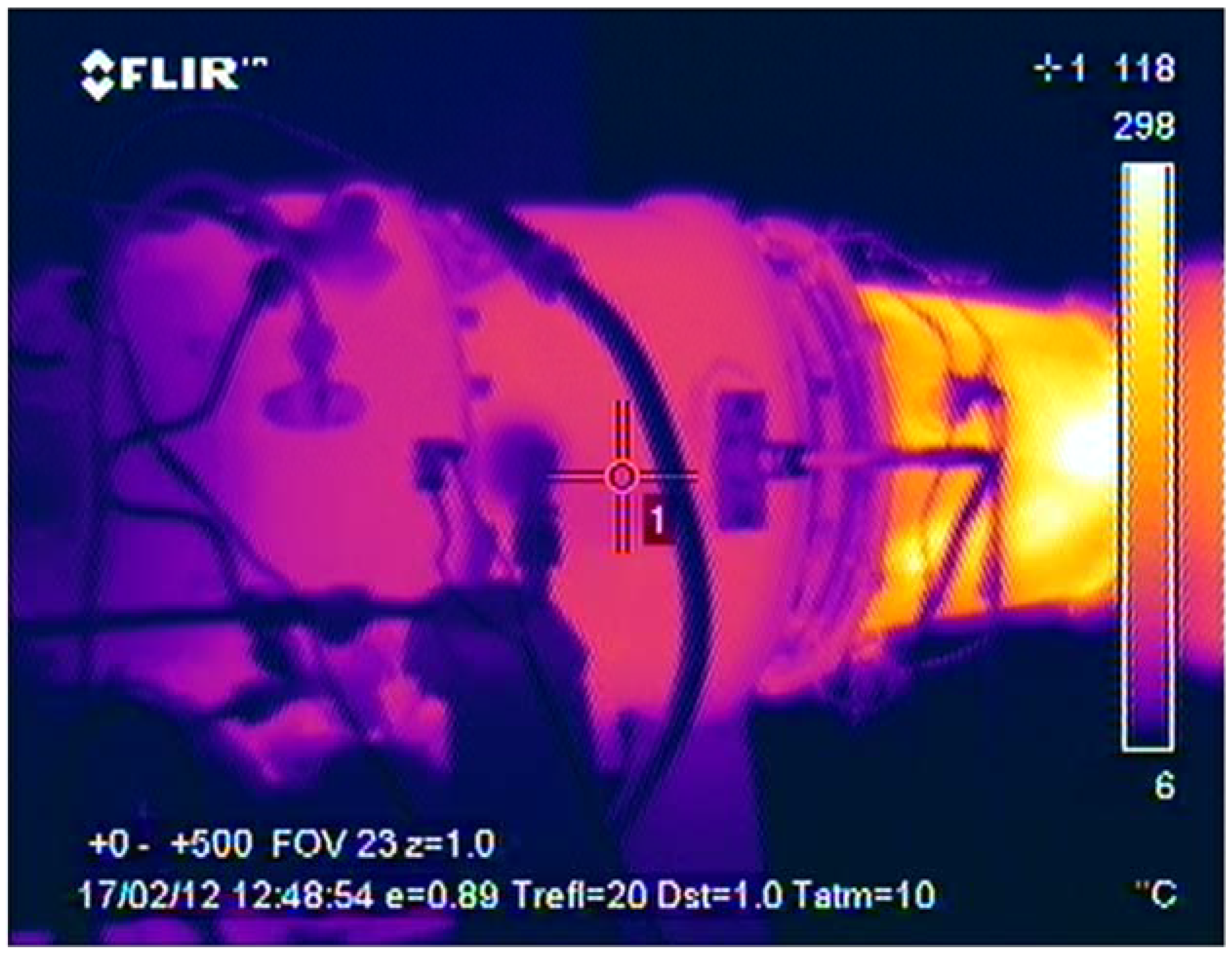
For the analysis and archiving of acquired thermograms, such as images depicting the distribution of surface temperatures, as in
Figure 9, the ThermaCAM Researcher program has been utilized. This program facilitates the connection of a thermal imaging camera to a computer, enabling high-speed data transfer and control of all camera functions. The outcomes of measurements obtained from a system or process can be conveniently exported in the form of charts, providing a visual representation of the data.
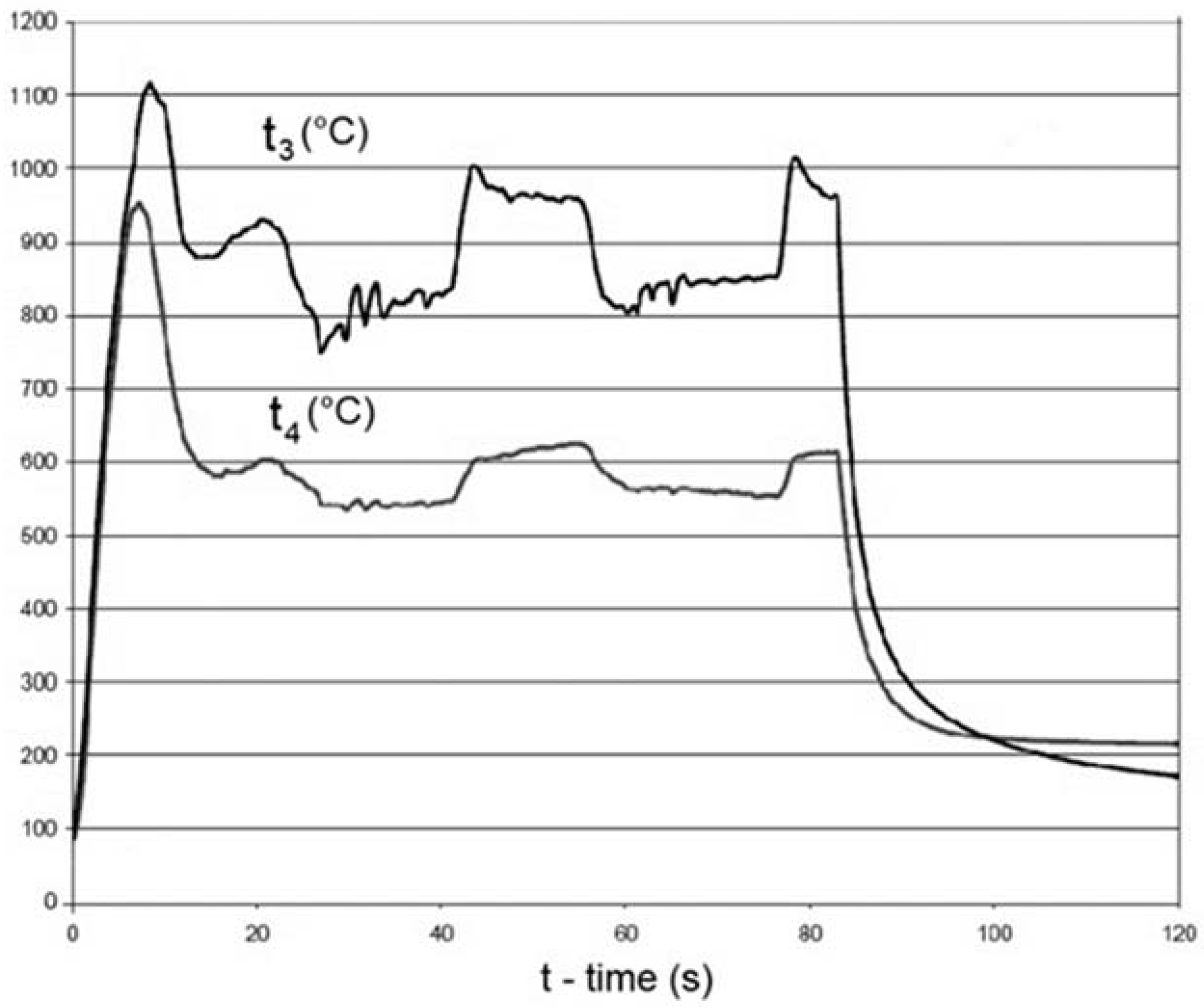
Figure 10 depicts two temperature values, denoted as t
3 and t
4. The former signifies the temperature measured at the section precisely at the gas turbine outlet, recognized as the location with the highest temperature concentration. The latter represents the temperature measured at the section located anterior to the gas turbine outlet. Charts can be customized to display the desired data range and can be exported in various file formats suitable for further analysis or presentation purposes. The exported charts can be used to identify patterns and anomalies in the data and can be utilized to make informed decisions.
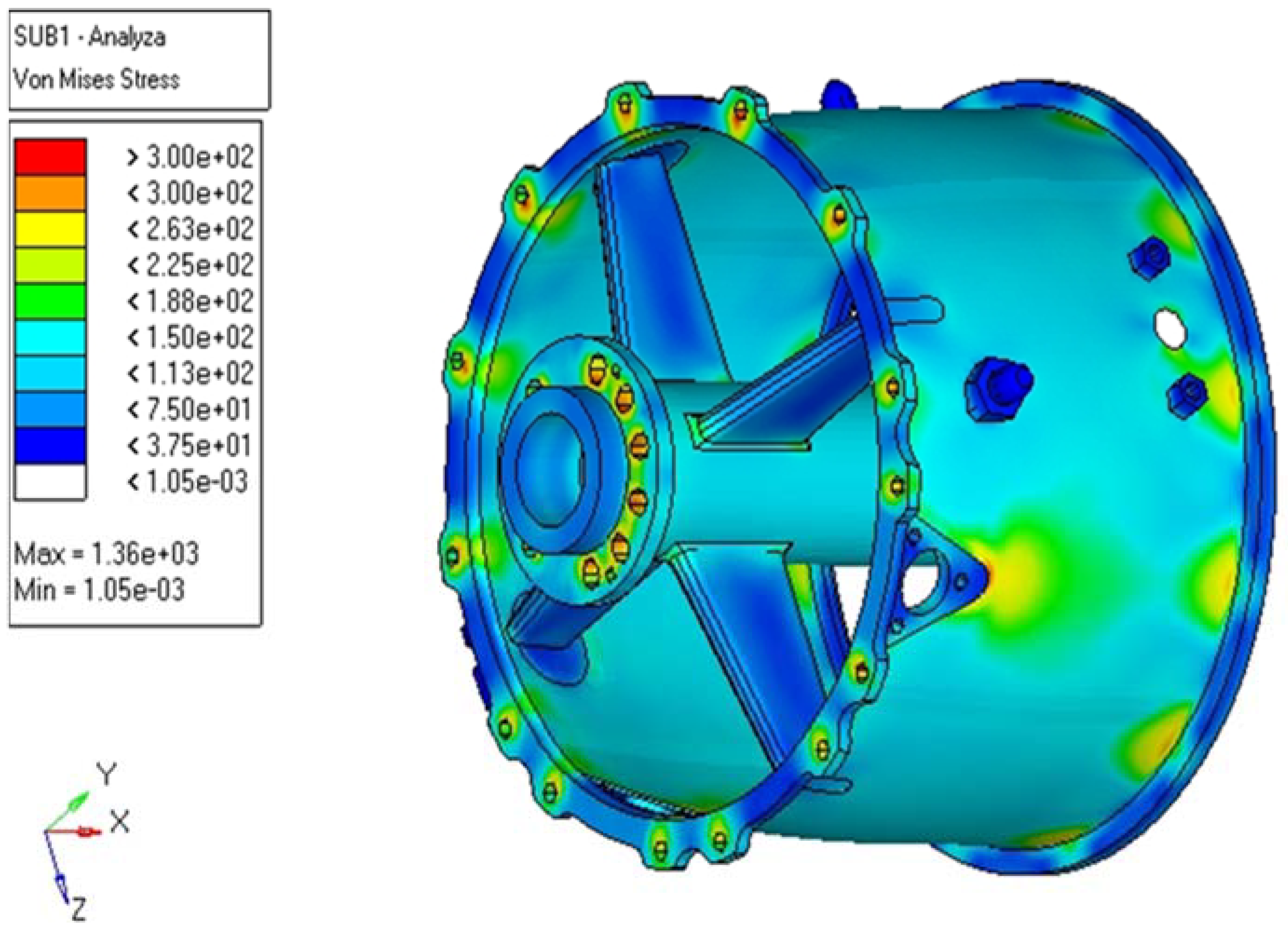
The monitoring of stress development arising from thermal expansion was conducted as the selected construction element underwent heating from the reference temperature to its final temperature, e.g., from 40 °C to 120 °C. As anticipated, the manifestation of thermal expansion and heightened stress was notably accentuated at the specific junctures where individual structural elements interconnect, namely, the joints. As illustrated in
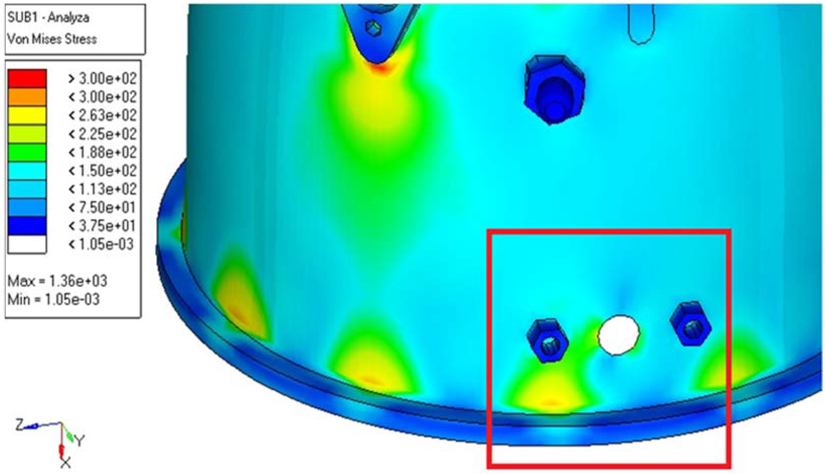
Figure 11, regions exhibiting brighter colors denote escalated stress attributed to thermal expansion. One of the contributing factors is the compromise in structural integrity incurred during the creation of these joints, either during welding processes or at locations where screws are employed. These areas are particularly susceptible to the influence of thermal expansion.
Sensor placement zones can fulfill the required function without plastic deformations. All stress values determined by simulation are below the material limit of the slip limit. The selected structural component greatly exceeds the requirements for safety values for the limited state of flexibility during the most critical phase of combustion. The findings outlined above are highlighted through the creation of a visualization of the chosen simulation, with a focus on the location and position of the markers and sensors (
Figure 12).
The primary objective of this analysis was to ascertain the local stresses induced by thermal expansion at the locations on the combustion chamber cabinet where temperature sensors are strategically positioned. Upon evaluating the strength of the selected structural element, no notable critical issues were discerned within the modeled scenarios, as substantiated by the visualization generated.
4. Discussion
As aeronautical engineers strive for continuous improvement in the performance and reliability of aircraft propulsion systems, a meticulous investigation into the localized stresses arising from thermal expansion becomes paramount [
26,
27,
28]. In this study, advanced digitalization techniques were employed, utilizing CATIA modeling software and a 3D scanner, to evaluate the locations on the combustion chamber cabinet where temperature sensors are positioned. The principal aim was to assess the structural integrity of these pivotal areas under the thermal stresses encountered during operational conditions. The initial phase of the methodology involved the application of CATIA, a cutting-edge modeling software, to construct a digital representation of the combustion chamber. This digital twin not only facilitated a comprehensive analysis but also served as a foundational reference for subsequent evaluations. The incorporation of a 3D scanner into the experimental framework enabled the meticulous capture of intricate details of the actual component, ensuring precision and reliability in simulations (
Figure 13).
A comprehensive analysis of a digitalized turbojet engine was undertaken within a HyperMesh working environment. This platform facilitated the execution of finite element analysis and the simulation of the influence of thermal expansion on the combustion chamber shell. Valuable insights into the stresses induced at locations accommodating temperature sensors were obtained through the simulations. Following a careful examination of the outcomes, the conclusion is that no significant issues concerning structural integrity were disclosed within the modeled scenarios. The visualizations derived from the analysis serve to bolster the findings by presenting a clear depiction of stress distribution across the combustion chamber cabinet. These visualizations, deemed invaluable tools for engineers and researchers, offer insights into potential vulnerabilities and contribute to the refinement of design parameters. It is noteworthy that the analysis did not discern any critical issues, underscoring the robustness and reliability of the combustion chamber structure when subjected to thermal expansion. This positive outcome stands as a testament to the advancements in simulation technology, which enabled the precise replication of real-world conditions and the accurate assessment of structural responses.
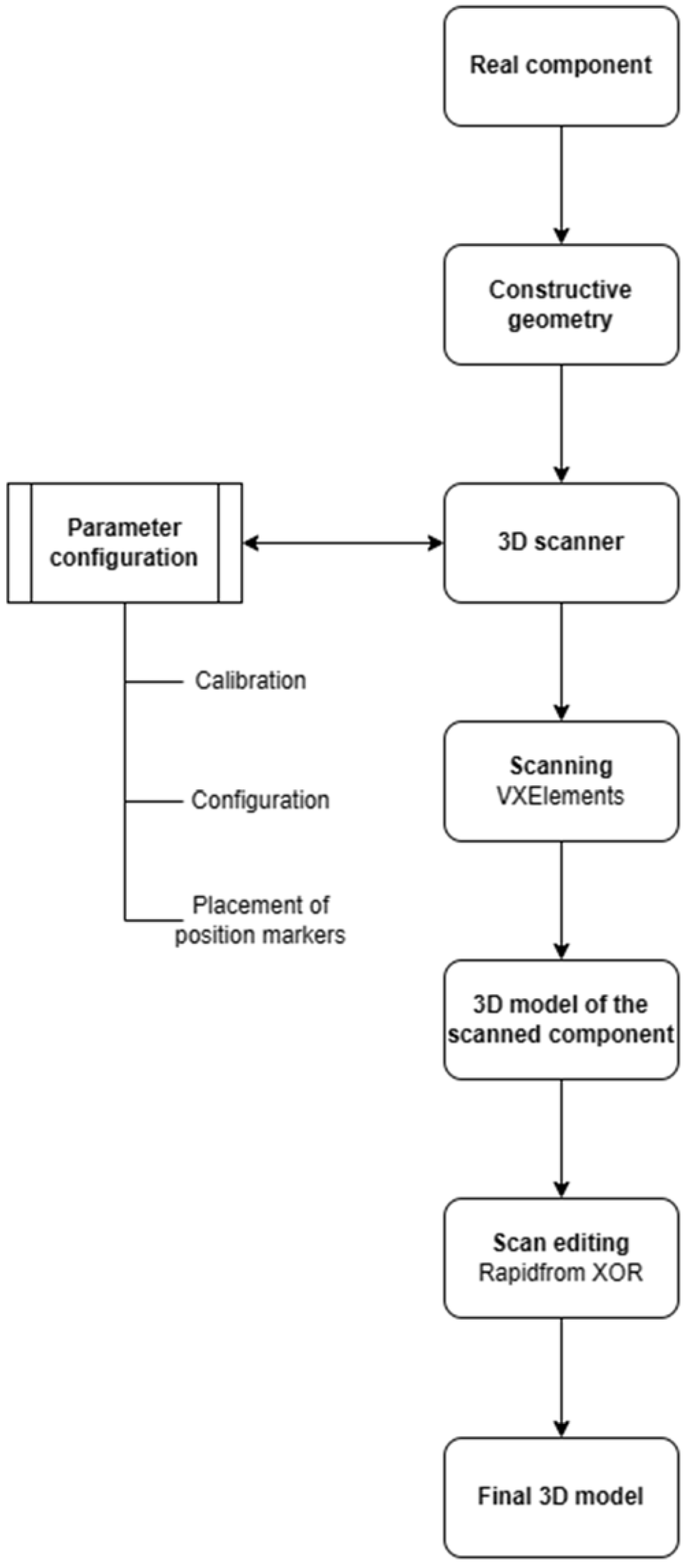
To establish transparent and reproducible procedural steps within the methodology, the utilization of visualization in the form of a flowchart was employed. The objective was to augment clarity and facilitate a more accessible comprehension of the process. In consideration of the intricacies inherent in the study, considerable effort was dedicated to the development of a detailed but generalized flowchart that encapsulates the fundamental steps inherent in the used approach (see
Figure 14). This flowchart serves as a visual roadmap, outlining the sequential progression from initial digitalization using CATIA to the execution of thermal analysis within the HyperMesh environment. Each step was systematically documented, highlighting the integration of 3D scanner data and the critical parameters considered during analysis. The methodology is streamlined for future reference using a generalized flowchart, and collaboration is facilitated by presenting a concise overview of the research framework. The commitment to methodological rigor and scientific transparency is underscored by the visual representation, ensuring that the approach is accessible and reproducible for the broader scientific community.
A comprehensive analysis of local stresses induced by thermal expansion in the combustion chamber cabinet of a turbojet engine is presented in this study. The attainment of a holistic understanding of structural behavior under challenging operating conditions has been facilitated through the integration of CATIA modeling software and a 3D scanner, in conjunction with the capabilities of HyperMesh and thermal analysis. This research contributes to the ongoing efforts in enhancing the reliability and performance of aircraft propulsion systems.
5. Conclusions
In general, it can be said that CAx systems are used in every part of the enterprise to cover the process of design, construction, simulation, analysis, and even maintenance and production [
29,
30,
31]. The theoretical part of this article presents a description of the current state of solving the problem of using CAx systems. In particular, such includes current CAx systems used in the aviation industry, their development, and the selection of the aircraft design node, on which we pointed out the use of CAx systems for practice. The research activity thematically follows from the theoretical part of the article. Its goal is to design a suitable CAx system for the creation of visualization and simulation of the aircraft structural unit, to propose a method of modeling the selected aircraft structural unit, and then to implement the selected simulation using CAx systems for the selected element of the aircraft structural component.
The summary of the main contributions of this article to the development of the theory and methodology of designing aircraft structural components can be summarized in the following points:
Creation of 3D models (considering the actual shape and dimensions) of individual construction elements of the aircraft structural component. Utilization of 3D scanner and specialized software.
Application and development of selected graphic modeling methods and tools in the field of designing aircraft structural components utilizing CAx software.
Conduction of thermal stress testing on a real aircraft component, the small jet engine MPM-20.
Thermal stress testing of its digital twin.
Analysis of the obtained data.
Formulation of knowledge usable for modeling the design of other structural components of the aircraft.
This study highlights the use of a 3D handheld scanner to create a visualization of 3D models for aircraft structural units. Implementation and experimental verification of the creation of visualization of 3D models of individual construction elements of the aircraft structural unit using a 3D handheld scanner, along with verification of data collection used for simulation using new technology, could be highlighted as practical benefits of this study. The implementation of the proposed benefits in the design of aircraft structural nodes brings numerous advantages [
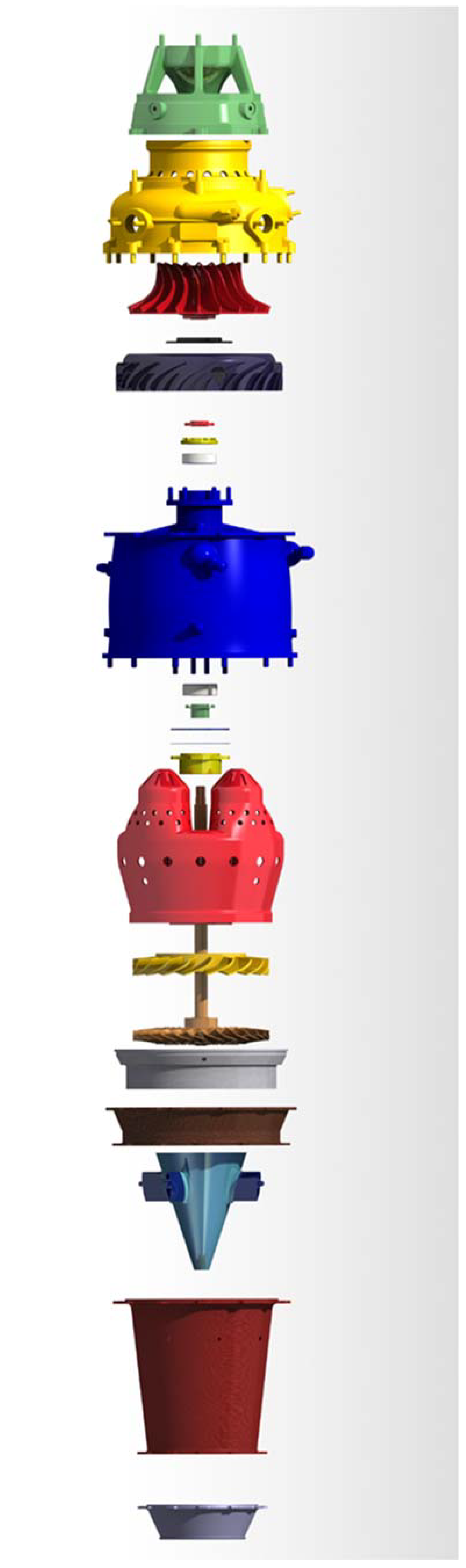
32]. These include reducing redundant design steps; increasing the efficiency of designing aircraft structural components; and accelerating the creation of 3D models of individual construction elements, as well as the complete assembly. The final assembled CAD model is shown in
Appendix B,
Figure A2.
Data obtained by testing a real object, a small MPM-20 jet engine, and data obtained by simulating thermal entrainment on its digital twin and comparing them confirmed predictions of where thermal expansion and stress would be most noticeable. Drawing from this conclusion, it is reasonable to indicate, by observing the necessary methodology and using best practices, that testing the temperature load on the digital twin of the selected component yields identical results as testing the real object in laboratory conditions. When verifying the results, the places with the highest temperature load were identical. This testing method therefore also represents a contribution to the field of non-destructive testing (NDT) of structural components, where these results and findings can be applied to other industries outside of aviation, such as the automotive and engineering industries. The simulation was conducted to compare and validate results with temperature tests performed on a real object. The testing of the real object occurred under laboratory conditions at the laboratory of intelligent aircraft control systems, Faculty of Aeronautics TUKE. The potential for replacing real component testing with simulated testing of a component’s digital twin exists, providing strict adherence to procedures for creating a digital twin to ensure the highest possible resemblance to its real-world counterpart. This potential is significant, particularly in terms of the utilization of CAx tools and Industry 4.0 concept tools in the context of aviation, known as Aviation 4.0, as a tool for the conduction of NDT testing, not only of aircraft components.


