Review

Performance of Unreinforced Masonry Walls in Compression: A Review of Design Provisions, Experimental Research, and Future Needs

by
Abrahem A. Ali Blash
1,†,
B. H. Abu Bakar
1,*,
Ufuoma Joseph Udi
1,
Bassam S. A. Dabbour
1,2,
Azhar Ayad Jaafar
1,
Li Yanhao
1,3,
Ilyani Akmar Abu Bakar
4 and
Majed Rashed
1
1
School of Civil Engineering, Engineering Campus, Universiti Sains Malaysia, Nibong Tebal 14300, Pulau Pinang, Malaysia
2
Department of Engineering Sciences and Applied Arts, University College of Science and Technology, Khan Younis P.O. Box 8, Palestine
3
School of Civil and Architectural Engineering, Yangtze Normal University, Chongqing 408100, China
4
School of Civil Engineering, College of Engineering, Universiti Teknologi MARA, Shah Alam 40450, Selangor, Malaysia
*
Author to whom correspondence should be addressed.
Current address: Department of Civil Engineering, College of Engineering Technology, Houn 61160, Libya.
Appl. Sci. 2023, 13(22), 12306; https://doi.org/10.3390/app132212306
Submission received: 20 October 2023 / Revised: 9 November 2023 / Accepted: 10 November 2023 / Published: 14 November 2023
(This article belongs to the Special Issue Feature Review Papers in Civil Engineering)

Abstract

:
Unreinforced masonry (URM) is a construction of brick or concrete block unit that is joined together using mortar, without steel reinforcement. Because of the heterogeneous nature and difference in mechanical properties of the masonry elements, analyzing and capturing the structural behaviour of URM walls under various loading conditions is therefore complex. In recent decades, research efforts have been focused on addressing and understanding the compressive behaviour of URM walls from the experimental viewpoint. However, from the existing experimental literature, there is a significant degree of variation in the mechanical and geometric properties of URM walls, especially the comprehensive comparison of apparently equivalent test parameters, which has yet to be examined. It is therefore necessary to highlight and critically examine major results derived from the experimental literature to better understand the performance of URM walls under compressive loads. This review paper presents the assessment performance with regard to axial compressive tests on URM walls, along with comprehensive comparisons among the experimental literature findings on the basis of masonry construction methods and various influencing parameters. Emphasis in the literature has been placed chiefly on the masonry elements, design provisions, axial load, slenderness ratio, openings, and stress–strain response. Based on observations from the study, experimental development trends have been highlighted to identify and outline potential directions for future studies.

1. Introduction

A masonry wall is the structural assemblage of masonry elements, i.e., bricks or blocks with mortar as the binding material. Masonry walls and the building as a whole are designed to be durable, stable, and resilient under sustained loading. In masonry construction, the imposed loads are supported and transmitted to the foundations by the bricks or blocks joined together by mortar and, in some cases, are filled with grouts and reinforcements. One significant benefit of masonry building—aside from the ease of construction with readily available basic materials—is the durability of masonry materials such as the unit, which, with proper selection, could be expected to last for several decades, if not centuries, with very little maintenance [1]. Despite the ease with which masonry buildings are constructed, the analysis of its structural behaviour still remains a difficult challenge.
Unreinforced Masonry (URM) walls are largely non-homogeneous, non-elastic, and anisotropic elements made up of two materials with very different characteristics—one element of either mortar or unit considerably stiffer than the other—and a relatively weak bond between them [2,3,4]. Thus, masonry walls are relatively weak in tension. As a result, the walls are usually designed and expected to resist only compression loads [5,6,7,8]. Over the last several decades, research studies have been dedicated to investigating the structural behaviour of masonry walls and improving design standards [9,10,11]. In particular, significant attention has been focused on masonry components and the interaction between them. The walls of a structural masonry building serve as the primary resisting component against dynamic or static loads exerted on the structure, and as such, its compressive strength is of utmost importance when designing masonry walls in different loading conditions. In addition, the compression behaviour of masonry walls is a key factor in the design of masonry structures for other actions, such as in-plane shear and out-of-plane flexural behaviour [12]. However, the analysis of masonry walls under axial compressive load has been largely overlooked in the past.
In recent years, several research studies have been dedicated to investigating the axial compressive behaviour of URM walls [13,14,15,16,17,18,19,20,21,22,23]. In general, the mechanical properties of each masonry element and bonding properties between mortar and units are of major significance in the compressive behaviour of URM walls as a composite material. As a result, the behaviour of axially loaded URM walls becomes very complicated because it is dependent on several factors relating to the slenderness ratio and eccentric loading conditions of the walls. Moreover, multiple provisions in the masonry design standards are stipulated in predicting the strength of URM walls under axial compressive loading [24,25,26]. Nonetheless, there are discrepancies observed in existing design standards to predict the compressive strength of URM wall structures, particularly in the guidelines in choosing and testing of wall configurations. Based on these constraints, previous experimental investigations focused on the effect of various factors on the strength of the URM wall. As such, a detailed comparison of the experimental literature is required.
There are reviews that provide information about masonry structures, especially for in-plane damage analysis of the masonry [27,28,29] and also for out-of-plane failure analysis [30,31,32,33,34,35]. However, these review articles do not focus on the axial compressive loading of URM walls alone. There is also a recent review on the behaviour of masonry prisms in compression [36], but these types of specimens do not reflect the deformation behaviour of full-scale walls in compression due to the slenderness effect and the possibility of non-uniform load distribution. Taking into account the masonry structures which are prominent in developing countries, this present study is therefore limited to reviewing and assessing the existing experimental literature on the compressive performance of URM walls, with a particular focus on concrete block and clay brickwork, which are the most common types of masonry building currently in service. A comprehensive literature survey was carried out for a variety of influencing parameters to assess available experimental literature data, as well as to demonstrate the vastly different predictions of masonry compressive strength from various masonry standards. Special consideration is given to adopted construction methods by taking into account the unit type, unit and mortar strength, slenderness ratio and eccentricity, and opening effects in URM walls.

2. Review of Design Provisions and Concepts

This section provides a concise overview of the design guidelines specified for URM walls in four commonly used masonry design codes, with a focus on their capacity to resist axial compression. Additionally, this section succinctly addresses the inclusion of grouted masonry compressive strength, the approach to addressing slenderness, and the consideration of eccentricity with the design standards.

2.1. European Masonry Standards

The load-carrying capacity of a masonry wall is solely determined by its susceptibility to compression failure. The design methodology for a masonry cross-section, as per Eurocode 6 [24], is based on the principles of rigid-plastic material behaviour and involves a verification process across three distinct sections (top, middle, and bottom). This verification aims to establish the minimum capacity reduction factor, accounting for factors like slenderness and eccentricity. The load-carrying capacity of URM walls, as defined by Eurocode 6 for masonry constructed with general-purpose mortar, is represented by Equation (1).
f k = 0.55 f b 0.70 f m 0.3
where f’k is the characteristic compressive strength of the masonry; fb denotes the normalized compressive strength of the unit; and fm represents the mean compressive strength of the mortar. The thickness of the mortar bed joints is limited to a maximum of 15 mm. It is important to note that Eurocode 6 refers to the characteristic compressive strength of the masonry, diverging from the literature, which often pertains to the mean values. Mean properties are typically used for assessing existing structures, while characteristic values are more appropriate for new structures. For determining the reduction factor values in relation to slenderness and eccentricity at the wall’s top or bottom, it is recommended to use a rectangular stress block, as represented in Equation (2).
Φ i = 1 2 e i t
where t represents the wall thickness and ei denotes the eccentricity of the wall, calculated using Equation (3), and as shown in Figure 1. Mid is the design value of the bending moment at the top or bottom of the wall. Nid is the design value of the vertical load at the top or bottom of the wall; ehe is the eccentricity at the top or bottom of the wall, if any, resulting from the horizontal load; and einit is the initial eccentricity. In cases where the slenderness ratio of the URM wall surpasses 12, second-order effects also need to be taken into account. It is noteworthy that Eurocode 6 [24] only provides design expressions for the compressive strength of unreinforced masonry. Consequently, the evaluation of grouted URM strength can be determined using EN 772-1 [37] or via a compressive strength test on masonry wallette as specified in EN 1052-1 [38]. The recommended minimum compressive strength for grout stands at 12 MPa.
e i = M i d N i d + e h e + e i n i t > 0.05   t

2.2. Canadian Masonry Standards

In Canada, the standard method for structural design is the limit states design, which applies to masonry, as well as other construction materials. According to the CSA S304.1-14 [25] standard, limit states are defined as conditions where a building structure no longer fulfils its intended function. This standard serves as a guideline for masonry design and specifies the prescribed values for the compressive strength of unreinforced masonry via tabulated data that correspond to specified unit strengths. The Canadian standard introduces a constraint whereby the maximum resistance of URM walls against axial load is limited to 80%. This implies that the axial load-bearing capacity should not surpass a specified value, denoted as P, and is represented as Equation (4).
P = 0.8   Φ m   0.85 f m A e
where Φm represents the material resistance factor for masonry and f’m denotes the specified compressive strength of the masonry. The effective cross-sectional area, Ae, represents both the mortar bedded area and the area of voids filled with grout. The Canadian standard also provides designated values for the compressive strength of grouted masonry. The standard dictates that the minimum compressive strength of grout, prepared according to specified guidelines and cast in non-absorbent cylinder moulds, should fall within the range of 10 MPa to 12 MPa. In cases where test data are unavailable, an assumed in situ grout strength of 20 Mpa can be adopted.
Recognizing the practicality that axial loads are seldom applied accurately along the centroidal axis of a masonry wall and absolute vertical alignment is rarely achieved, clause 7.7.3 of the Canadian standard stipulates that the eccentricity of axial load application must not be less than 10% of the wall’s thickness at both ends. The Canadian standard also specifies the following slenderness limits:
  • For k h / t < ( 10 3.5 e 1 / e 2 )   n e g l e c t   s l e n d e r n e s s   e f f e c t ;
  • For k h / t > 30 r e v i s e n o t   a p p l i c a b l e ;
  • For 30 > k h / t > ( 10 3.5 e 1 / e 2 )   a c c o u n t   f o r   s l e n d e r n e s s   e f f e c t ;
where kh is the effective height of the wall, and the values e1 and e2 correspond to the smaller and larger virtual eccentricities at the ends of the wall, respectively.

2.3. Australia Masonry Standards

The guidelines for designing URM walls under axial compression in Australia, as outlined in AS 3700, 2018 [26], ensure the safe and efficient construction of masonry walls that do not contain any reinforcing elements such as steel bars or mesh. In the previous edition of the Australian masonry design standards, AS 3700, 2011 [39], the maximum compressive strength for grouted masonry was set at 1.3 times the compressive strength of the masonry units. The lower limit for grout strength was 12 Mpa. However, the approach to incorporating grout strength has been revised in the updated version. The new requirement stipulates that the grout strength must be equal to or greater than the characteristic compressive strength of the masonry, with an upper limit of 50 Mpa. Consequently, the design expression for URM walls subjected to axial compressive loads has been revised based on the expression provided in Equations (5) and (6).
P = Φ f m A b                                         u n g r o u t e d   U R M
P = Φ f m A b +   f g f c g 1.3   0.55 + 0.005 f c g   A g         g r o u t e d   U R M
where Φ is the capacity reduction factor, which takes different values depending on the type of masonry: 0.5 for unreinforced hollow masonry, 0.6 for unreinforced grouted masonry, and 0.75 for unreinforced solid masonry. Ab refers to the bedded area of the masonry unit, while fg denotes the compressive strength of grout. F’m is the characteristic compressive strength of the masonry, while f’cg is the design characteristic compressive strength of the grout. Ag denotes the design cross-sectional area of the grout.
AS3700 permits a simple assumption that when a roof or floor connects to a wall, its load can be regarded as acting with an eccentricity equal to one-third of the bearing thickness. Each side of the wall is considered to be supported by half of the bearing thickness if the floor or roof spans across the wall. In this approach, the vertical load coming from the level above is assumed to be centred at the level under consideration. Figure 2 depicts these simplified assumptions for evaluating eccentricity. In the case of a slab connected to either a solid wall or one leaf of a cavity wall (as shown in Figure 2a), the resulting eccentricity is computed using Equation (7). For a slab that spans continuously over a solid wall (as shown in Figure 2b), the resulting eccentricity is calculated based on Equation (8)
e = W 2 × t w 6 W 1 + W 2
e = W 2 W 1 × t w 6 W 1 + W 2 + W 3

2.4. American Masonry Standards

The axial compression design provisions for URM walls in MSJC [40] exhibit a similarity to those outlined in the CSA S304 [25]. Consequently, the design values are confined to compressive strength ranging from 10.34 to 27.58 MPa for concrete masonry units and 10.34 to 41.37 for clay brick units. Using tabulated data enables the determination of allowable compressive strength for grouted masonry. The compressive strength of grout must meet or exceed the specified compressive strength of the masonry unit and should not fall below 13.74 MPa. The code further outlines upper limits for grout strengths: 41.37 MPa for clay brick and 34.47 MPa for concrete masonry. Based on the recommendations proposed in the MSJC [40], the nominal axial compressive strength should not exceed Equations (9) and (10) for members with an h/r ratio not greater than 99 and for members with an h/r ratio greater than 99, respectively.
P = 0.8   0.8 A e f m 1 k h 140 r 2    
P = 0.8   0.8 A e f m 1 70 r k h 2    
where f’m is the specified compressive strength of the masonry, Ae is the effective cross-sectional area of the wall, kh is the effective height of the wall, and r is the radius of gyration.

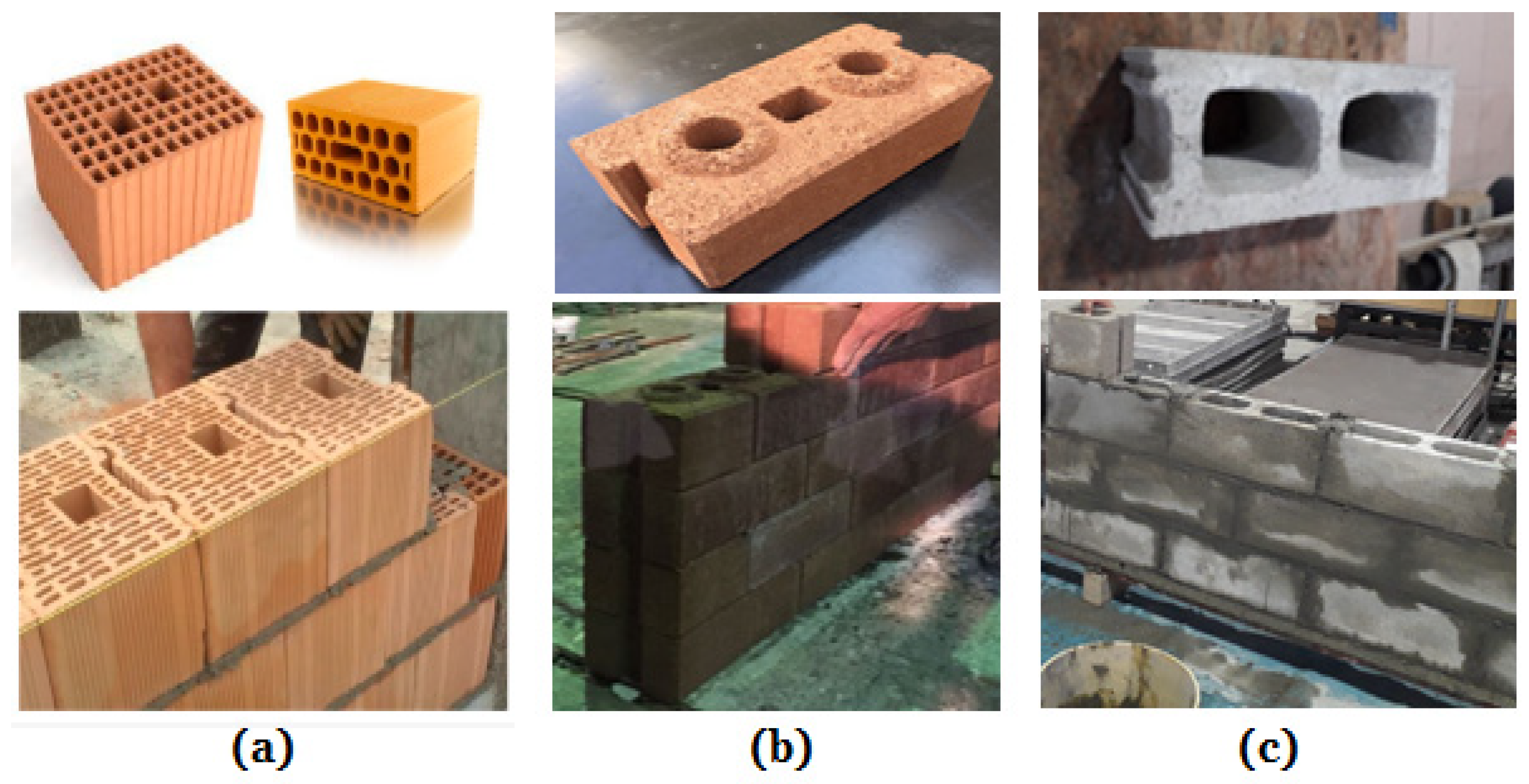
3. Masonry Units in Construction

Masonry wall units such as blocks or bricks are primarily made of concrete, calcium silicate, and clay. Blocks and bricks come in a variety of forms, shapes and sizes, including solid, hollow, and interlocking (e.g., see a selection in Figure 3). All these units have roughly comparable functionalities, but their properties vary markedly and are dependent on their constituent raw materials employed and their mode of production. Besides solid block and brick units, hollow concrete blocks (HCB) are widely attractive nowadays in low- and medium-rise constructions due to their advantages like light weight, ease of construction, and higher load-bearing capacity, as well as their ability to facilitate conduits for concealing electrical units, sewer, and water pipes [9,41,42]. Under similar conditions, the quantity of masonry mortar used to lay HCB can be lowered by more than 50% when compared to solid concrete blocks, thereby significantly lowering construction costs.
With regard to masonry unit characteristics, its compressive strength is the most important. In addition to being closely associated with the strength of the wall, the properties of the unit provide an overall indicator of the masonry characteristics [43]. It is evaluated using standardized tests, and the results rely largely on the conditions and recommendations specified in the relevant standards in use. It can be said that the axial compression behaviour of masonry blockwork differs considerably from brick masonry since not only does the mortar strength influence the axial compression response but also the type and shape of block unit and strength of grout can inadvertently influence the overall response of the masonry wall [6,36,42]. Clay bricks can be made with compressive strength as high as 100 N/mm2, but modest strength, i.e., 20–40 N/mm2, is usually adequate for low-rise residential construction and the cladding of walls in medium-rise constructions. Concrete block units have lesser normalized strength, which ranges between 2.8 and 35 N/mm2, but the effect mentioned previously must be considered if comparisons are to be made. In addition, the strength of brickwork will be lower than that of the corresponding blockwork if made from clay units with a similar strength value [44]. Although mortar represents only about 7% of total masonry volume, it has a far greater impact on performance than this fraction suggests. Conventional mortar mixtures are composed of cement, sand, plasticizer, or lime, and the mortar mix is graded based on its compressive strength [45]. The stiffer the mixture, the less it can facilitate movement, and thus, it is not recommended to employ a stronger mixture than required to satisfy performance requirements [44].
Various types of concrete blocks are also available, such as aerated autoclaved concrete (AAC) [46,47], whose material density ranges from 450 to 850 kg/m3 and enables the sizeable solid unit to be handled without mechanical support. The use of core-aligned blocks with special geometries, such as the Double H block [48], interlocking bricks [49,50,51,52,53], cellular lightweight concrete (CLC) [54,55,56], and three-cell concrete block [57], have also garnered a lot of attention in recent years. The development of these newer types of blocks necessitates corresponding research into the adequacy and durability of such blocks for continued usage in masonry construction, and in particular to walls subjected to compressive loads.

4. Overview of Experimental Research in the Literature

As previously stated, various construction and testing parameters can influence the compressive performance of URM walls. The primary factors are the strength of masonry units (brick/block) and mortar strength, as well as the slenderness ratio and eccentric load conditions of the walls [17]. Apart from these parameters, the presence of openings is another significant parameter which could affect the performance of the masonry structure and should be properly taken into account. All the above-mentioned parameters can be varied during the construction and testing of masonry walls, leading to a more accurate assessment of the design of load-carrying URM elements.
When evaluating the structural response of URM walls, both shear capacity and bending moment should be considered by taking into account its interaction with compression forces due to lateral load and gravity [58,59,60]. In the context of masonry structures in general, substantial eccentricity loadings could be precipitated either by in-plane or out-of-plane lateral forces or a combination of both [61]. The latter are typically induced by thrusting components (e.g., vaults and arches), wind and soil pressures and seismic actions transmitted from the masonry floor. In contrast, the former can be seismic-induced shear force ensuing from box-type global seismicity of the building structures. As observed from the literature (e.g., see ref. [62]), axial loading differs from eccentrically loaded walls since the former is a statically determinate problem in which the strength of a given wall panel may be presumed to be maximum compression forces divided by the total cross section (Figure 4). On the contrary, eccentrically loaded wall panels are statically indeterminate problems in which the bending moment could be defined by integrating the normal stress and the corresponding axial strain over the given gross sectional area [63,64,65]. As a general recommendation in the design of URM structures, the capacity reduction factor (Φ)—expressed as a ratio of prism strength to the strength of the wall—can be introduced to accommodate and account for different characteristics and to obtain the permissible compressive strength of the masonry [24,40,66].
In evaluating the axial compressive performance of URM walls, experimental tests carried out on brick and concrete block masonry wall specimens available in the literature have been analyzed (e.g., see a selection in Table 1). However, it is important to highlight that previous research on the compressive behaviour of full-scale masonry walls is still limited. To augment the understanding, tests conducted on wallettes and partially grouted wall panels subjected to axial compressive loading have been used since the actual behaviour of these types of wall panels is identical to full-scale URM wall panels [12]. In addition, URM wall panels subjected to shear–compression loading have also been examined. However, the results from such experiments reported in the literature were not included in the database since these types of tests are closely associated with earthquake loadings.
Based on a series of assumptions, scholars have introduced a wide range of predictive models to estimate the compressive strength of masonry. These models vary from simple linear ones with a single variable to complex nonlinear ones that consider the influence of multiple variables. Linear models were proposed in [67,68], while nonlinear expressions were introduced via standards such as Eurocode 6 [24]. These expressions established correlations between the compressive strength of masonry and both the compressive strength of the unit and the compressive strength of mortar. In many cases, the expressions proposed did not consider any distinctions based on the type of masonry. However, beyond the compressive strength of masonry constituents, additional factors were considered by researchers like Khan et al. [69]. The authors introduced a mathematical model that takes into account the slenderness ratio (height-to-thickness ratio, h/t) and the width-to-thickness ratio (l/t). A summary of the expressions proposed in the literature for calculating the compressive strength of masonry wallettes is provided in Table 2.
The following sections present a review of the literature on the compressive performance of URM walls, summarizing the work and salient observations made by earlier researchers in different experimental campaigns. Code provisions have also been compared with results from experimental studies, and disparities are highlighted to identify and outline potential directions for future studies.
Table 1. Overview of experimental studies on compressive tests of unreinforced masonry.
ReferenceYear of PublicationUnit TypeMaterialWall DimensionsNo. of SamplesProperties of Masonry Elements (MPa)Test Parameter
H × L × T (mm)fbfmfg
Camacho et al. [13]2015HCBConv. concrete1000 × 900 × 14098.64; 15.76717Axial load; stress–strain.
Fortes et al. [14]2017HCBHigh-strength concrete2200 × 1200 × 140,
2200 × 800 × 140
3018.7–34.513.4–26.931.3–42.4Axial load; stress–strain.
Keshava and Raghunath [16]2017Brick
SCB
HCB
Table moulded;
Conv. Concrete;
Conv. Concrete.
2500 × 950 × 220;
2560 × 1030 × 150;
2600 × 830 × 150
145.8
4.5
6.0
9.4Axial load; slenderness ratio and eccentricity.
Amalkar et al. [17]2020CCB
HCB
Conv. Concrete;
Conv. Concrete.
2667 × 802 × 200;
2680 × 800 × 200, 2680 × 830 × 150
97.1
13.7; 6.6
5.3Axial load; slenderness ratio and eccentricity.
Dharek et al. [18]2021HCBConv. Concrete.2600 × 845 × 152.28.865.323.5Axial load.
Hasan et al. [19]2021HCB
Brick
Conv. Concrete;
Clay.
300 × 200 × 150–1200 × 750 × 150247.5–19.2
5.8
7.5Axial load.
Gumaste et al. [15]2007BrickTable moulded;
Wire-cut
520 × 600 × 105;
520 × 665 × 230
95.7
23.0
0.8–6.6
0.6–12.2
Axial load, elastic modulus.
Watstein and Allen [21]1970BrickExtruded wire-cut940 × 685 × 94–3716 × 3200 × 97.3654.2–174.310.0–48.6Axial load; slenderness ratio and eccentricity.
Kirtschig and Anstotz [22]1991SCBCalcium silicate;
Lightweight aggregate.
635 × 1000 × 115–3120 × 1000 × 1156420.9
4.1
5Axial load; slenderness ratio and eccentricity.
Hendry and Malek [70]1987BrickClay;
Lightweight AAC
590 × 665 × 102
590 × 665 × 215
4828.8–92.4
4.4
17.6; 27.4Axial load; stress–strain
Fattal and Cattaneo [71] 1976Brick
HCB
Wire-cut
Conv. Concrete
2438 × 812 × 90
2438 × 812 × 140
5690.2
8.5
10.4Axial load; stress–strain.
Khan et al. [69] 2023BrickFired-clay530 × 410 × 75;
445 × 445 × 75
1816.1–20.25.0; 6.7Axial load.
Milani et al. [72]2021BrickClay965 × 580 × 140814.6–19.65.8Axial load; stress–strain.
Calderón et al. [73]2023BrickMulti-perforated clay745 × 745 × 140919.5–22.37.6–28.0Axial load; stress–strain.
Bergami and Nuti [74]2015BrickClay1010 × 1010 × 260; 770 × 770 × 1204810.4–23.323.4; 11.7Axial load.
Jafari et al. [75]2022BrickClay; CS430 × 475 × 100;
880 × 300 × 100
210 × 180 × 100
5413.1–36.4 Axial load; stress–strain; shear compression.
Costigan et al. [76]2015BrickFired-clay 512.71.4–22.2Axial load; stress–strain.
Zhu et al. [77]2017HCBConv. concrete990 × 590 × 190625.7515.55-Axial load.
Sandoval et al. [78]2011BrickClay238 × 300 × 35; 896 × 300 × 35.3632.57.3Axial load; slenderness ratio and eccentricity.
Mohammed et al. [79]2009BrickFired-clay1700 × 1700 × 10212805.3–11.6 Axial load; stress–strain; opening.
Zhou et al. [80]2017HCBConv. concrete990 × 590 × 1902414.1–31.16.3; 15.5Axial load; stress–strain.
Thamboo and Dhanasekar [81],2019BrickClay;
Compressed-earth
410 × 430 × 100; 590 × 570 × 140403.8–15.8
6.5; 7.9
6.4; 3.9Axial load; stress–strain.
Note: HCB = hollow concrete block, SCB = solid concrete block, CCB = cellular concrete block, CS = calcium silicate, AAC = autoclaved aerated concrete, Conv. = conventional, fb = compressive strength of unit, fm = compressive strength of mortar, fg = compressive strength of grout.
Table 2. A summary of selected equations proposed in the literature for predicting either the characteristic compressive strength of the masonry, fk, or the mean value, f’m, using the normalized compressive strength of the unit, fb, and the compressive strength of the mortar, fm.
ReferenceMasonry TypeModel
Eurocode 6 [24]Clay and calcium silicate unitsf’k = 0.55 fb 0.70 fm 0.3
Gumaste et al. [15]Calibrated for table moulded brick masonryf’m = 0.317 fb 0.866 fm 0.134
Khan et al. [69]Calibrated for clay brick wallettef’m = f b   ( 4 + 0.1 f m 1.5 l / t + 5 h / t )
Hendry and Malek [70]Calibrated for clay brick masonryf’m = 0.317 fb 0.531 fm 0.208
Costigan et al. [76]Calibrated for fired clay brick wallettef’m = 0.56 fb 0.53 fm 0.5
Zhou et al. [80]Calibrated for HCB wallettef’m = 0.886 fb 0.75 fm 0.18

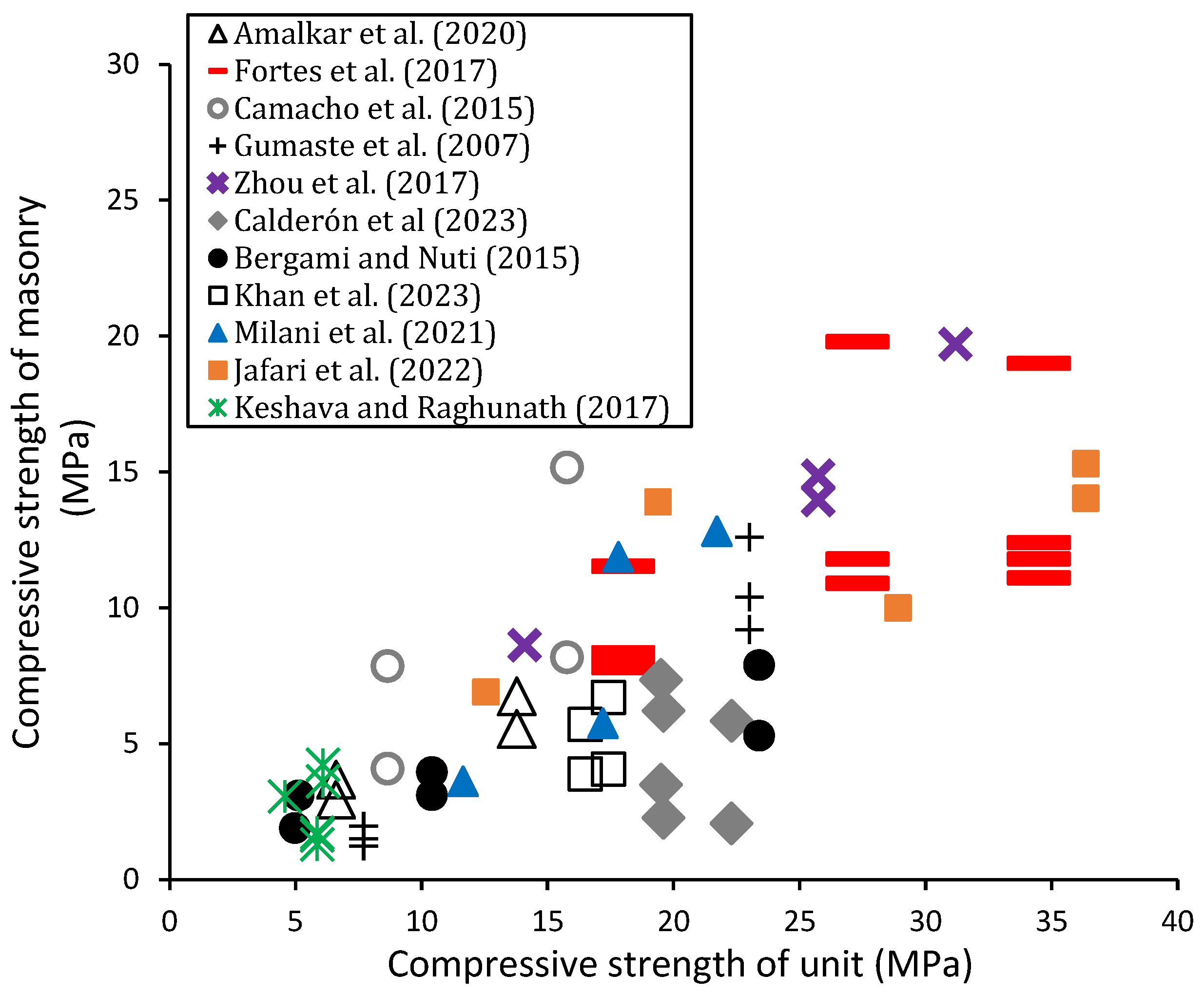
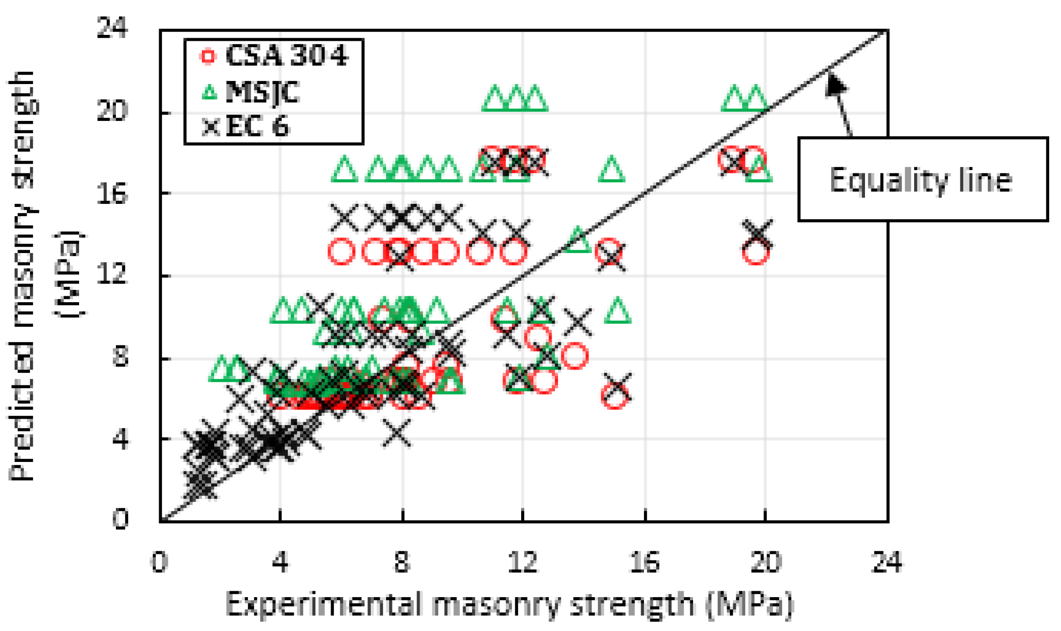
4.1. Effect of Strength of Components and Loading Orientation

In real-world situations, the majority of masonry buildings are typically stressed in compression. As a result, it is of significant importance to assess masonry’s compressive strength for which challenging problems exist to test full-scale wall specimens. In recent decades, several experimental campaigns have been conducted to assess the compressive strength of small-scale specimens, i.e., masonry prisms, for which comprehensive reviews have been published (see ref. [36]). However, the strength values of these types of specimens may not be representative of the actual performance of full-scale walls. It is for this reason that several scholars have conducted a significant number of experimental campaigns to study the axial load response of URM walls. Results from past studies indicate that the load-bearing capacity and deformation behaviour of URM walls are closely related to the relative strength of the individual masonry element, production and test procedure, as well as the geometry of the test walls.
Recent research generally confirms the widely accepted fact that higher unit strength results in improved compressive strength for URM walls constructed using different types of units. The studies reviewed in this present article indicate that the type and strength of the unit have a significant impact on the compressive strength of URM walls. As depicted in Figure 5a, the majority of the walls constructed with concrete units had compressive strength values ranging from 3.28 to 19.8 MPa, which are typically higher than the compressive strength observed in walls built using clay units, which ranged from 1.1 to 13.9 MPa. Additionally, the majority of the walls constructed using concrete units exhibited a masonry efficiency—defined as the ratio between masonry compressive strength and compressive strength of unit (f’m/fb)—ranging between 35 and 96%. In contrast, the masonry walls built using brick units demonstrated f’m/fb values ranging from 11 to 76%.
For example, Keshava and Raghunath [16] carried out axial compression tests on fourteen full-scale URM wall panels made up of table-moulded bricks (fb = 5.85 MPa), solid concrete blocks (fb = 4.57 MPa), and HCB (fb = 6.08 MPa) available in South India. All walls were constructed using the same mortar strength (fm = 9.42 MPa). Observations from the study generally indicated that the HCB walls have better performance in load-carrying capacity among all three different types of blocks in the set of experiments. The compressive strength of the wall panels made with concrete blocks (hollow/solid) was found to be in the range of 3.05 and 4.2 MPa, while the strength of the wall panels made with bricks was found to be between 1.28 and 1.72 MPa, indicating the better performance in load capacity of concrete block walls in comparison to wall panels made with bricks. Similar findings are also observed in [17,19]. In the study by Amalkar et al. [17], in particular, the entire experimental campaign focused on cellular concrete blocks (CCB) and HCB URM walls. The test results—nine specimens in total—gave evidence of better performance in the load capacity of wall panels built with HCB in comparison to that of brick walls tested in previous experiments [15,16].
Such observations are also noted in [19], where HCB and brick masonry walls were tested in compression. Results from the study gave evidence—and in accordance with previous findings—that the HCB wall panels exhibit higher compressive strength in comparison to wall panels built with bricks. Camacho et al. [13] also reported a 100.2% increase in the compressive strength of full-scale URM walls built with HCB units (fb = 15.76 MPa) in comparison to masonry constructed with lower strength units (fb = 8.64 MPa). Likewise, experimental investigations by Milani et al. [72] on clay brick masonry wallettes constructed with a mortar strength of 5.84 MPa demonstrated that the compressive strength of masonry wallettes built with a unit strength of 19.61 MPa was 175.3% higher than those constructed with lower unit strength (fb = 14.23 MPa). However, the difference in the masonry strength was mainly attributed to the scale effect of the unit.
Traditionally, lower-strength mortar and stiffer units are used in the construction of URM walls. However, in recent years, engineers worldwide have encountered unique scenarios where mortar needs to be stronger than units. This can be attributed to various factors, including advancements in mortar cement properties and the necessity of using locally available soft units for affordable housing construction in developing nations [15,81,82,83,84]. A better understanding of how the relative strength of mortars and units affects the performance of URM walls under axial compression loads has been made possible by recent research that has been published in the last few years. According to research findings, when low-strength units are used, increases in mortar compressive strength have only a little impact on the compressive strength of the wall. Figure 5b graphically displays the compressive strength values of mortars relative to the compressive strength of URM walls, as reported in Table 1. The dataset is presented based on M1 (fm ranging between 0.86 and 2.6 MPa), M2 (fm = 5 and 11.9 MPa), and M3 (fm = 12.2 and 26.9 MPa) mortars used in the different experimental campaigns. The dataset in Figure 5b indicates that the ratio between the compressive strength of masonry and mortar compressive strength (f’m/fm) in M1 mortars ranges between 0.67 and 2.79 MPa. While M2 and M3 mortars presented f’m/fm values of 0.13 to 2.49 MPa and 0.13 to 1.27 MPa, respectively.
For example, Zhou et al. [80] carried out a test on 23 URM wallettes—590 mm × 990 mm × 190 mm their nominal sizes—using different block–mortar strength combinations, i.e., HCB (fb = 14.08 MPa, 25.73 MPa, and 31.18 MPa) and mortars (fm = 6.31 MPa and 15.55 MPa). An increment of about 80% in the compressive strength of the block was found to have caused a corresponding increase in the compressive strength of the wall panels by approximately 60%. On the other hand, an increment in mortar strength by about 150% was found to have caused an increase in the masonry compressive strength by only approximately 2%, indicating—and in accordance with prior studies [85,86]—that the strength of mortar has minimal influence on the strength of URM wall. The negligible effect of mortar strength on the compressive strength of unreinforced masonry was also observed in the study by Bergami and Nuti [74]. The authors observed that an increase in mortar strength by 100.4% only amounted to a 19% increase in the compressive strength of the wall. In contrast, an increase in the unit strength by 94.9% increased the strength of the masonry by about 155%. However, the influence of mortar joint thickness on full-scale URM walls constructed with different combinations of unit strength and mortar strength is unavailable in the experimental literature, thus drawing up possible lines for future research.
In recent years, the need to construct taller masonry structures has driven the construction industry to develop a robust capability for producing high-quality units with varying degrees of strength and geometric characteristics [14,87,88]. Consequently, there has been a growing importance placed on advancing the understanding of URM walls constructed using high-strength blocks [87]. However, it is worth highlighting that existing masonry codes do not include design procedures that account for the use of high-strength units. In this regard, Fortes et al. [14] conducted an articulated experimental campaign to study the performance of high-strength URM walls subjected to axial compressive loading. Grouted wall panels (2.2 m high, 1.2 m wide) and ungrouted wall panels (2.2 m high, 0.8 m wide) constructed with and without a mid-height bond beam were included in the set of experiments. Three different strengths of hollow concrete block and mortar were used: fb = 18 MPa, 27.3 MPa, 34.5 MPa and fm = 12 MPa, 18 MPa, 24 MPa. Observations from the experiments indicated an increment in compressive strength of grouted wall panels by about 50% in all the grouted wall panels in comparison to the un-grouted wall panels. Test observations also indicated that the use of a bond beam at the mid-height of the wall prevented a decrease in the compressive strength of the wall panels. However, the use of such special schemes altered the failure pattern of tested walls. In addition, results from the set of experiments also differ from code recommendations specified in [89], and this may be due to the geometry of blocks used in the study.
A number of studies have also indicated that the compressive performance of URM walls may be influenced by the loading orientation. Specifically, loading perpendicular to the bed joints is known as vertical compression and loading parallel to the bed joints is referred to as horizontal compression (e.g., see Figure 6). For example, recent experimental comparisons conducted by Khan et al. [69] revealed a higher compressive strength of masonry in the case of O1B1M1 and O1B2M2 wall specimens loaded in the vertical direction compared to P1B1M1 and P1B2M2 wall specimens loaded in the horizontal direction. Similarly, the experiments carried out by Bergami and Nuti [74] indicated that the compressive strength of hollow brick masonry is significantly affected by the strength of both the units and mortar. Essentially, stronger mortar contributes to the overall strength of the masonry panels, particularly under vertical compressive loading, where this effect is more pronounced than under horizontal compressive loading. Recent findings by Jafari et al. [75] gave further evidence that the strength of URM walls can be lower when subjected to horizontal compressive loads. Likewise, recent experimental investigations by Calderón et al. [73] on multi-perforated clay bricks masonry demonstrated higher compressive strength of wallette specimens loaded perpendicular to the bed joint compared to specimens loaded parallel to the bed joint, a fact mainly attributed to the internal configuration of the bricks (layout of webs and shells). This internal configuration impacts the resistant areas in each direction, consequently affecting the compressive performance of the walls.
Although several studies have reported that the performance of URM walls is affected by the loading orientation; however, all of these studies were conducted using clay bricks with essentially stronger units and weaker mortar strength. More studies focusing on URM walls—possibly in full scale—built with concrete block units, taking into account stiff mortar–weak unit combinations, should be considered to verify the axial compression performance based on the loading orientation.
Figure 7 plots the compressive strength of masonry (f’m) derived from the experimental campaigns discussed in this paper against the compressive strengths of units used in each campaign, while Figure 8 plots the normalized compressive strength of the masonry (i.e., f’m/fb vs. fb/fm) reviewed in this present article. Observations from the literature suggest that the strength of URM walls is largely influenced by the strength of the unit, i.e., the greater the unit strength, the greater the compressive strength of the wall, and this feature holds true for most of the experimental studies considered. However, as depicted in Figure 7, a significant degree of scatter on the compressive strength of URM walls can be observed from the experimental literature. A similar trend could also be observed in the normalized compressive strength of the masonry when considering all masonry types, as shown in Figure 8. The high degree of variation observed in the figures is mostly due to the different wall geometries and material units employed in the various campaigns.
As discussed in Section 2, existing design standards such as the Eurocode 6 [24] provide empirical expressions used to predict the compressive strength of masonry structures. On the contrary, masonry standards such as the CSA S304 [25] and MSJC [40] provide tabulated values to estimate the masonry’s compressive strength, accounting for various strength of unit and mortar combinations. In this present review article, the compressive strength values of URM walls were compared to the strength values predicted by the empirical equations proposed in the Eurocode 6 [24] and the tabulated values from the MSJC [40] and CSA S304 [25]. Figure 9 illustrates the comparison between the compressive strengths of URM walls derived from the experimental campaigns discussed in this paper and the compressive strengths predicted by the various design standards. The values tabulated in CSA S304 [25] were not applied to masonry constructed with mortars that could not be classified as type S or N according to CAN/CSA-A179 [90]. Furthermore, the tabulated values in MSJC [40] were not used to predict the compressive strength of masonry built with mortars that could not be classified as S, N, or M, as outlined in ASTM C270-19a [91]. Lastly, the predictions were not applied to URM walls constructed with units, mortar, or grout of strength classes and types not covered by CSA S304 [25] and MSJC [40]. It can be seen in Figure 9 that the empirical expressions recommended by Eurocode 6 [24] and CSA S304 [25] are more conservative than those proposed by MSJC [40]. Considering all masonry types reviewed in this present article, the model introduced by the Eurocode 6 [24] can be considered to be the most reliable one with the data reported in the experimental literature. Nonetheless, a substantial amount of the experimental data showed significant deviations from the equality line depicted in Figure 9. In many instances, the CSA S304 [25] underestimated the compressive strength of URM walls, with the exception of masonry constructed with high-strength concrete block units, whereas the MSJC [40] consistently overestimates the compressive strength of the analyzed cases.
These observations align with recent discussions presented by Zhou et al. [80], which indicate that existing design standards lack consistency and tend to make non-conservative predictions regarding masonry strength. Similarly, Fortes et al. [14] noted that the empirical expressions outlined in the masonry standards fail to adequately consider the significant impact of high-strength mortar on the compressive performance of URM walls built with high-strength concrete block units. This limitation is further supported by the findings of Thamboo and Dhanasekar [81], who pointed out that the existing strength formulations overestimate the compressive strength of the masonry, particularly in cases where low strength units (fb =< 5 MPa) are employed.
Furthermore, numerous research efforts have been dedicated to establishing empirical expressions that relate the compressive strength of unreinforced masonry with the compressive strength of mortar and masonry units. These expressions are often developed via statistical analysis of numerous tests conducted on unreinforced masonry walls in various countries around the world and to compare with the expressions provided in masonry design standards. From Table 2, it can be seen that the empirical relationships proposed by the various masonry design standards in predicting the compressive strength of unreinforced masonry show significant deviation from the empirical expressions proposed in the literature for most of the experimental studies considered. The studies examined in this paper emphasize significant shortcomings in the empirical expressions and tabulated values proposed in the existing design standards, underscoring the need for their urgent and thorough revision. Moreover, the compressive strength values observed in this present review article are much lower than those observed in the review of masonry prisms conducted by Nalon et al. [36]. In their recent review study, the authors reported compressive strength values ranging between 1.1 and 41.8 MPa when considering all types of masonry prisms [36]. In comparison, compressive strength values ranging from 1.1 to 19.8 MPa were observed for wallets and full-scale masonry walls reviewed in this present article. Based on the dataset reviewed in this paper, it appears that estimating masonry compressive strength via full-scale tests may be a more suitable approach than relying on the expressions and tabulated values proposed in existing masonry standards, which are mainly based on tests of small-scale specimens.

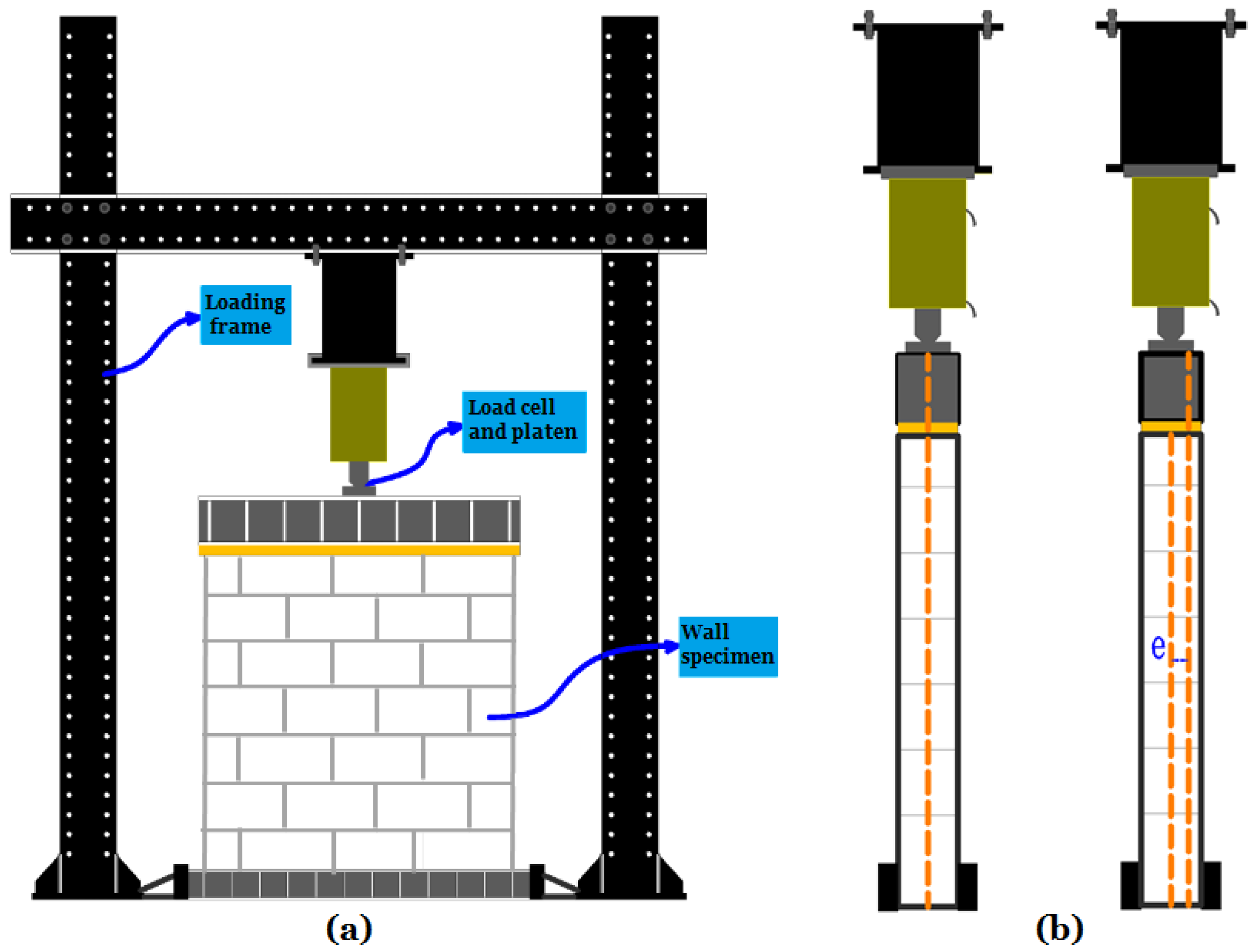
4.2. Effect of Slenderness Ratio and Eccentricity

The current design of masonry structures compensates for the eccentric gravity loads and wall slenderness by the introduction of the capacity reduction factor to the compressive strength of the masonry. In conventional masonry construction, the load-bearing wall structure is usually thick; therefore, the influence of slenderness could be neglected if the height-to-thickness (h/t) ratio is less than 10 [71]. The DIN 1053 [92] allows for a slenderness ratio of masonry walls up to 20, and just two better quality grades between 10 and 20 are permitted. Within this permissible range, only light loads are allowed on the masonry with slenderness greater than 14, and the strength of the material may be reduced by a factor (25-h/t)/15, whereas the Eurocode [24] permits a slenderness ratio of up to 27.
Within this constraint, Hasan and Hendry [20] investigated the influence of slenderness ratio and load eccentricities on the compressive strength of the URM wall and compared the results with the capacity reduction factors prescribed in the British code [93]. Tests were conducted on twenty-five brick walls using different slenderness ratios (i.e., 6, 12, 18, and 25), with various support conditions (hinged, RC slab, and flat end) and loading eccentricities (0, t/3, and t/6). Observations from the test results indicated a decrease in wall strengths of specimens tested with flat-end conditions with an increase in slenderness ratio, with the exception of specimens with a slenderness ratio of 12. The authors observed that in wall specimens tested with hinged support conditions and eccentrically loaded 0, the capacity reduction factor permitted in the British code is almost 10% less, with the exception of specimens having a slenderness ratio of 25, whereas in wall specimens tested with eccentricity t/3, the capacity reduction factor was about 25% greater than that permitted in the British code. However, in wall specimens with eccentricity t/6, the capacity reduction factor yielded almost identical value as that found in the British code. It is worth highlighting that while the maximum value of wall slenderness used in [20] is 25.0 and the values in [93] provide up to 46.1 slenderness ratio, the British code is now obsolete and is superseded by the Eurocode [24]. In the opinion of the authors, tests on masonry wall panels with a slenderness ratio higher than 30 are more a matter of academic rather than practical interest since the results obtained by the authors for wall panels loaded with zero eccentric loads were about 18% lower than that reported by Haller [94]. On the contrary, for wall panels loaded with t/6 eccentricities, the results obtained in [94] were higher than those obtained in [20].
Watstein and Allen [21] investigated the influence of different slenderness ratios (12.4, 22.8, 32 and 42.5 and eccentricities (0, t/6 and t/3) on the load capacity of full-scale brick URM wall panels constructed with low-strength and high-bond mortar. In the case of wall specimens having a slenderness ratio of 22.8 and loaded with eccentricity t/6, the strength of the walls built using high-bond mortar was 25% higher than the compressive strength of the same wall panels constructed using normal-strength mortar. Similarly, for wall specimens loaded with eccentricity t/3, the compressive strength of walls constructed using high-bond mortar was 33% higher than the resistance of the same wall panels constructed using lower-strength mortar. A similar finding was also reported by Kirtschig and Anstötz [22]. The authors investigated the effect of different slenderness ratios (5.6, 11.1, 18.8, and 27.7) on the strength of URM walls constructed using different heights (0.63 m, 1.25 m, 2.12 m, and 3.12 m) and different concrete blocks. Results from the study showed a reduction in load capacity in all tested wall panels with the increase in slenderness ratio (e.g., see Figure 10). Consequently, it can be inferred that URM walls exhibit maximum load-carrying capacity when their aspect ratio (i.e., l/h) is equal to 1. Fattal and Cattaneo [71] also gave evidence of a decrease in load-bearing capacity in HCB URM walls with the increase in eccentric loads, which was mostly accompanied by greater shattering at failure in tested specimens.
To complement previous experimental findings, Sandoval et al. [78] conducted an extensive analysis to study the axial performance of a large number of scale brick URM wall panels constructed using various combinations of slenderness ratio and eccentric loads. As expected—and in accordance with previous findings [21,22]—an increase in slenderness ratio and eccentric load significantly affected the strength of tested walls. Observations from the study indicated that the decrease in load-bearing capacity of wall panels having a slenderness ratio of 6.8 could vary between 25% and 40% and between 55% and 70% for walls with a slenderness ratio of 25.6 if eccentrically loaded at t/6 in comparison with walls loaded with zero eccentricity. Similarly, the reduction in load capacity for wall panels with a slenderness ratio of 6.8 could be between 60% and 75% and between 80% and 90% for walls constructed with a slenderness ratio of 5.6, if eccentrically loaded at t/3, in comparison with walls loaded with zero eccentric loads. The study findings emphasize the fact that the maximum load capacity of the URM wall reduces significantly with an increase in the slenderness ratio and eccentric loading.
For the sake of clarity, Figure 10a–c presents a comparison among experimental literature results. The comparisons are made in terms of f’m/fb, where fm is the maximum compressive stress of the URM walls and fb is the compressive strength of the unit used in the individual experimental campaign. The comparisons are made only between experimental tests having identical support conditions (i.e., hinge supports at both the top and bottom of walls) and eccentric loadings (e = 0, e = t/6, and e = t/3). Remarkably—and despite the different materials and geometry employed in the various experimental campaigns—similar trends can be seen between the slenderness ratios and normalized compressive strength in the majority of experimental results considered.
A common feature of these studies is that a decrease in wall slenderness will cause an increment in its compressive strength, which is duly recognized. Accordingly, this holds true if the URM walls are constructed using different thicknesses of units and tested with hinged support conditions under axial compression and eccentric loads. This phenomenon may not be true if the lateral and rotational restraint conditions are considered, for which limited experimental studies indicate an increment in thickness of URM walls built using various types of units did not cause a corresponding increase in the wall compressive strengths despite the reduction in slenderness ratio [16,17]. In addition, observations in [23] indicate that the strength of the masonry is dependent on the height of the wall rather than its slenderness since experimental tests on two walls (270 cm high, 25 cm and 38 cm thick) constructed with bricks (25 × 12 × 6·5 cm) resulted in the same axial compressive strength despite the difference of wall slenderness ratios [23].
Amalkar et al. [17] noted that the capacity reduction factor prescribed in the various masonry standards underestimates the strength of URM walls. The authors conducted tests on nine full-scale walls, which were constructed using different slenderness ratios and tested under axial and eccentric loads. The capacity reduction factor (CRF) of CCB and HCB masonry walls obtained experimentally was compared with the various national codes such as the Indian standard [95], the British code [93], the Eurocode [24], and the Australian standard [26]. The results showed that for both axially and eccentrically loaded cases, the CRF derived experimentally for walls built with CCB seems to be higher than the values prescribed in the various codes. A similar trend was also observed for HCB walls with a slenderness ratio of 14.9. However, HCB walls with a slenderness ratio of 11.3 indicate lower experimental CRF values when compared to code recommendations. Likewise, Keshava and Raghunath [16] noted that the CRF prescribed in the masonry standard seems to underestimate for axially loaded brick/block walls and overestimate eccentrically loaded brick walls. Hence, it is of utmost importance to reassess the capacity reduction factor values by conducting more tests on URM walls and also to prescribe the values of the capacity reduction factor separately for concrete block and brick masonry.

4.3. Effect of Openings

The failure mechanism of solid masonry under compression is well-established based on previous research. Failure usually occurs due to the incompatible elastic properties of the masonry units and mortar. This leads to the formation of vertical cracks in either the units or mortar parallel to the direction of the applied compressive load [36,80,81,96,97]. However, in recent decades, one aspect of structural masonry walls which has piqued the interest of scientists is the design and failure behaviour of URM wall panels with openings subjected to compressive loads. Openings in masonry buildings are required to be provided in the wall for the functional needs of new buildings or functional alterations to an existing structure. These openings are of vital importance in designing building structures, particularly for spatial optimization and repurposing for long-term conditions. However, the openings constitute a vulnerability and may size-dependently decrease the stiffness and load capacity of the walls relative to the equivalent walls without an opening [3,79,98]. In particular, the presence of window or door openings in URM walls may affect the load path, leading to unfavourable stress concentrations at the corners of the opening under the applied compressive loads. These stresses are the main cause of the propagated cracks, which lead to final failure [80]. However, the current American [40] and Canadian [25] masonry design standards do not provide design rules for masonry wall panels with openings, while Eurocode 6 [24] specifies some limitations. Within this constraint, very few experimental works have been carried out in the past on masonry walls using various opening configurations in order to understand the behaviour of such walls under axial compressive loads, as well as to develop or verify analytical failure models.
Mohammed et al. [79,99] reported axial compression test results on fired clay brick masonry wall panels with small openings (380 × 380 mm2 opening area). As seen in Figure 11, typical vertical cracks were observed in the tested walls, and the location of these cracks was largely influenced by the position of the openings. Moreover, a significant reduction in the cracking load value was also reported for wall panels with openings compared to solid panels without openings. Test observations demonstrated that the reduction in load-bearing capacity and post-cracking stiffness is directly related to the position of the openings [99]. Chong [100] also reported a series of test results on the behaviour of full-scale brick masonry wall panels—5600 mm × 2475 mm × 50 mm their nominal sizes—with different opening sizes under lateral loads. Four different forms of opening configurations were considered, being representative of doors and windows. Observations from the study, as expected, gave evidence of significant differences in crack patterns and failure modes of wall specimens due to differences in opening size and positions (see Figure 11). Wallet strengths also proved to be conservative relative to the ultimate load capacity of the full-scale wall panels. The strength of the walls with openings (less than 10% of the total wall area) was around 25% lower than that of walls without openings.
Similar observations are also noted in [101], where the authors conducted a comparative study on the axial load response of full-scale URM walls with different opening configurations. The wall specimens—1200 mm × 1200 mm × 110 mm, their nominal sizes—were made with clay brick and an opening size of 400 mm × 800 mm (approximately 22.2% of the wall area). While the wall panels failed as a result of vertical cracks, the cracking patterns of the tested walls, as expected, differed significantly due to the presence of openings. The authors also gave evidence of a reduction in the load capacity by about 35% in addition to the increase in maximum displacement by 27% due to the presence of openings.
Although openings are a significant and integral aspect of masonry structures, experimental research in this area has not been given adequate attention. Further experiments are therefore required to improve the understanding of how openings affect the deformation behaviour of masonry walls subjected to axial compression. Future research should also prioritize walls with openings constructed with HCB units since this type of wall is currently unavailable in the experimental database.

4.4. Stress–Strain Behaviour

The compressive stress–strain relationship can be used to estimate the material properties of masonry, i.e., its strength, elastic moduli, and stress distribution under compressive loads [9]. Since masonry structures are constructed with different and non-homogenous elements, they can display typical behaviour that is non-elastic and anisotropic [23,36,102,103]. Prior investigations [9,85,86,104,105] indicated that the stress–strain profiles of unreinforced masonry constructed with stiff unit–soft mortar combination tend to exhibit greater nonlinear behaviour up to the point of maximum load compared to masonry constructed with stiff mortar–soft unit combination. These studies suggest that the compressive strength of the unit is the primary factor influencing the overall strength of the masonry, while the other component properties may merely alter the deformation path of the structure.
For example, Fortes et al. [14] observed that the individual properties of mortar and grout only had minimal influence on the shape of the stress–strain curve of full-scale walls constructed with three different unit strength (fb = 18 MPa, 27.3 MPa, and 34.5 MPa); mortar strength (fm = 12 MPa, 18 MPa, and 24 MPa); and grout strength (fg = 31.3 MPa, 34.9 MPa, and 42.4 MPa). Observations from the test results indicate that for walls with bond beams at a middle section, the stress–strain curve is linear up to approximately 70% of the failure load. In grouted wall panels without bond beams at the middle section, the stress–strain curve of these test specimens was linear up to about 60% of the ultimate failure load (e.g., see Figure 12). Similar results were also noted in the study conducted by Thamboo and Dhanasekar [81], which investigated the stress–strain response of URM wallettes constructed using bricks with compressive strength of 3.8 MPa and 15.8 MPa, along with two different mortar types: a stiff mortar (mix ratio 1:3) with compressive strength of 6.48 MPa and a weaker mortar (mix ratio 1:5). Two cases of clay and compressed earth brick wallettes (particularly specimens CLB1 and CLB2) are shown in Figure 12. The authors noted that the masonry specimens built using the 1:3 mortar displayed significantly lower compressibility, particularly beyond the linear elastic regions of the curves, compared to masonry specimens constructed with 1:5 mortar. However, it is worth highlighting that, regardless of the unit–mortar combination, the authors did not verify the complete descending portions in the stress–strain profiles.
Accordingly, Costigan et al. [76] verified that the existing prediction models prescribed in the masonry standards do not consider the various failure modes of unreinforced masonry or the onset of the nonlinear stress–strain curves. Two cases of clay brick wallettes (particularly CL90s and M6 specimens) are also shown in Figure 12. Costigan et al. [76] explained that unreinforced masonry wallettes constructed using stiff unit–softer mortar combinations exhibit significant deformations at the start of the compression loading regime due to the early plastic deformation of the mortar. This was subsequently followed by an upward, relatively linear segment occurring between 30% and 60% of the peak load level. Beyond this point, typically above 60% of the peak load, the curve ceases to be linear, and the material reaches its maximum stress, ultimately leading to failure. In contrast, the masonry built with a combination of stiff mortar and softer units exhibited a different behaviour. Initially, it absorbed high stress with minimal deformation, followed by abrupt failure with very limited plastic deformation. These findings emphasize the significant influence of mortar properties on masonry deformation. This aligns with findings reported in [106], which indicated that the stress–strain relationship becomes progressively nonlinear as mortar strength decreases. Costigan et al. [76] further noted that for the stress–strain curve prescribed in Eurocode 6 [24], the descending portion of the curve can only be applied to mortars with fm value greater than 7 Mpa.
The peak strain is an important parameter that characterizes the behaviour of masonry when subjected to axial compression. Despite its significance, the topic of indirectly estimating the peak strain corresponding to the masonry’s compressive strength has received limited attention. The Eurocode 6 [24] recognizes the nonlinear nature of the stress–strain relation of unreinforced masonry under compression. It assumes the curve to be linear up to 0.33, the characteristic compressive strength of the masonry (i.e., 0.33fm), or can be considered to be a parabolic curve, rising up to a strain of 0.002, or as a horizontal plateau in the stress–strain curve up to a strain of 0.0035 (e.g., see Figure 12). Based on regression analysis of experimental results, other authors have proposed expressions to deduce the peak strain in relation to the strength of full-scale masonry, its mortar strength and elastic modulus (see a selection in Table 3).
A novel rational model for a nonlinear stress–strain curve for HCB masonry wall structures subjected to axial compressive loading was proposed by Zhou et al. [80]. Testing was carried out on 23 URM wallettes—590 mm × 990 mm × 190 mm, their nominal sizes—using three different block/mortar strength combinations, i.e., HCB (fb = 14.08 mPa, 25.73 mPa, and 31.18 mPa) and mortars (fm = 6.31 mPa and 15.55 mPa). Results from the study indicated that a reduction in mortar strength produced a corresponding increase in the peak strain of the wall panels, confirming that the mortar properties greatly influence the deformation characteristics of URM walls, contradicting the observations noted in [9,105]. The model proposed in [80] produced results comparable to the stress–strain curve observed in all tested specimens from the early stages, via the upward curve and up to 20% of the ultimate load in the descending curve. However, in the latter stage of the downward curve, the proposed model failed in predicting the response of the downward curve since the strain continues to infinity with larger ultimate stress. Despite this, the proposed model is presumed adequate for use in the design and numerical analysis of HCB masonry walls.
A new model for correlating the compressive stress–strain curves of masonry prism to that of wallette was also proposed by Thamboo and Dhanasekar [81], based on axial compression tests conducted on clay and compressed earth bricks. Results from the study confirm that the compressive strength of wallette is more representative of full-scale wall panels since the strength results derived from the set of wallette tests were more conservative than those obtained from the prism tests. The authors noted that the proposed constitutive relationship was in good agreement with results obtained from the experiments since the model can be used to convert the prism strength to the equivalent wallette strength and incorporated into the design of real-world structural walls using the design standards. However, such a conversion is only applicable to solid blocks and bricks and thus cannot be further applied to other types of masonry walls. Hence, more laboratory experiments on URM walls—possibly on full scale—utilizing concrete block units and testing using different wall set-ups are needed to account for the discrepancies.
Although several experimental works have focused on the compressive behaviour of URM wall structures, limited literature efforts are still available on the stress–strain behaviour of URM with openings under axial loads. In the case of walls with openings, for example, the strain response at the openings, which may encourage local stress concentrations and ultimately determine the load path of wall panels when under axial compressive load, should also be properly taken into account. In this regard, Mohammed et al. [79] carried out an extensive experimental campaign to study the strain behaviour of full-scale brick URM walls—1700 mm × 1700 mm, their nominal sizes—with different opening configurations under compressive loading. Lintel blocks were used at the top of the openings, and two different boundary conditions were assigned to test specimens: fully restrained (fixed end) at the bottom of the wall panels, while the top edges were either fixed end or left free. High localized strains were noticeable in close proximity at corners of openings, and these strains appeared to reduce with an increase in the distance of openings from the width direction. The authors also observed that the inclusion of openings in the wall panels enabled the transfer of the load path to the lintel support by an arching action formed at the top of the openings. However, the different types of boundary conditions assigned to the walls during the tests showed insignificant effects on the strain results, which was attributed to the small value in the slenderness ratio of the wall panels. Further detailed studies on the axial compressive stress–strain behaviour of URM walls utilizing full-scale specimens are strongly recommended.
The elastic modulus of masonry is usually derived from the secant modulus of the linear portion of the stress–strain curve. The Eurocode 6 [24] recommends that this segment of the curve should typically be defined at service load conditions (i.e., at one-third of the peak stress), whereas the MSJC [40] recommends that the modulus be estimated at a stress level of 5 to 33% of the maximum compressive strength of the masonry. While the theoretical relationship between the elastic modulus and compressive strength may be considered irrelevant, it holds practical significance. Generally, the masonry’s compressive strength and elastic modulus exhibit a linear correlation. According to MSJC [40], the elastic modulus can be estimated at 700 times the compressive strength of the masonry. The Eurocode 6 [24] and AS 3700 [26], on the other hand, both suggest the elastic modulus be estimated as 1000 times the masonry’s compressive strength, while the Canadian standard [25] recommends a value of 850. Notably, some researchers have also proposed nonlinear expressions between the masonry’s compressive strength and its elastic modulus, as shown in Table 4.
Furthermore, the secant elastic modulus values examined in this present review article were compared against the predictions made by the expressions provided in the Eurocode 6 [24], MSJC [40] and CSA S304 [25], as depicted in Figure 13. Indeed, it can be seen that the data presented exhibit a significant degree of variation when compared with the expressions proposed in the various masonry standards. Specifically, when considering all types of URM walls, the ratio between the Young modulus and the compressive strength of the masonry ranges between 181 and 1928. Figure 13 illustrates that the modulus of elasticity predictions prescribed by the MSJC [40] tend to be more conservative than those recommended by the Eurocode 6 and CSA S304 [25]. This is evident as a significant amount of the data reviewed in this article deviates from the equality line shown in Figure 13. This extensive variability underscores the diverse behaviour and characteristics observed across different masonry compositions and configurations. The least accurate predictions of the elastic modulus values were observed in URM walls built with high-strength concrete, given that a majority of the data points were situated below the equality line in Figure 13. Thus, future research should prioritize enhancing the predictive accuracy of URM walls built with a combination of high-strength units and high-strength mortar.

5. Concluding Remarks

Unreinforced masonry walls represent one of the most commonly used structural systems in low and medium-rise buildings worldwide. The compression behaviour of masonry walls is a key factor in the design of masonry structures for other actions, such as in-plane shear and out-of-plane flexural behaviour. Thus, an accurate assessment of the masonry performance when subjected to axial compressive loads is required for the appropriate design and analysis of masonry elements. Despite the importance of this subject area, experimental campaigns on the compressive performance of URM walls are still very limited in comparison to the extensive research related to their in-plane and out-of-plane behaviour. Nonetheless, experimental literature efforts have been increasing in recent years and are discussed in this present paper.
The analysis of the experimental literature findings suggests a high degree of scatter in the geometric and mechanical properties of the units, which makes it challenging to compare results. While a relatively small number of wall specimens were tested squarely in axial compression in a large percentage of the tests, a majority of test specimens were constructed with clay brick units, few were built using hollow concrete block and far fewer with solid concrete block units. The strength distribution of URM walls showed a high variability due mostly to the heterogeneous composition of masonry elements, as well as the relatively small number of full-scale wall specimens tested.
The effect of unit strength and mortar strength on the compressive strength of masonry walls were also observed in graphs constructed based on the reviewed dataset. In general, higher unit strength results in significant improvement in the compressive strength of URM walls. However, an increase in the compressive strength of URM walls is only marginal if a combination of high-strength mortar and lower unit strength are used. The studies reviewed in this present article also indicate that the type of the unit has a significant impact on the compressive strength of URM walls. The majority of the walls constructed with concrete units had compressive strength values ranging from 3.28 to 19.8 MPa (masonry efficiency values ranging between 35 and 96%), which are typically higher than the compressive strength observed in walls built using clay units, which ranged from 1.1 to 13.9 MPa (masonry efficiency ranging from 11 to 76%).
Also, the empirical relationships proposed by the various masonry design standards to predict the compressive strength and elastic modulus of unreinforced masonry show significant deviation from experimentally obtained compressive strength and elastic modulus values for most of the studies considered in the literature. The least accurate predictions of the compressive strength and elastic modulus values were observed in URM walls built with high-strength concrete. Moreover, the compressive strength values observed in this present review article are much lower than those observed in a recent review of masonry prisms. Based on the dataset reviewed in this paper, it appears that estimating masonry compressive strength via full-scale tests may be a more suitable approach than relying on the expressions and tabulated values proposed in existing masonry standards. This limitation underscores the need for an urgent and thorough revision.
The analysis of the experimental literature findings indicates that the compressive strength of URM walls can also be affected by several other factors, including the slenderness ratio, loading eccentricity, and the loading orientation. Specifically, URM walls loaded perpendicular to the bed joint revealed higher compressive strength values compared to walls loaded parallel to the bed joint. Also, the capacity reduction factor derived from the experimental literature generally revealed higher values in comparisons with code provisions for most of the experimental studies considered. This limitation signifies the utmost importance of reassessing the capacity reduction factor values by conducting more tests on URM walls and also to prescribe the values of the capacity reduction factor separately for block and brick masonry.

6. Recommendations for Future Research

Existing experimental works focused on various influencing parameters such as unit strength, mortar strength, loading conditions, slenderness ratio, openings, etc. Observations from the experimental literature indicate that while some aspects have been given substantial consideration, some others require further detailed investigation.
In most of the tests with hinged support both at the top and bottom of the wall panels, a reduction in the slenderness ratio can cause a corresponding increase in the compressive strength of the walls. However, this may not be true when the lateral and rotational restraint conditions are considered, but the sample size of experiments is too small to make a proper comparison. More experimental tests utilizing different boundary conditions, tested under axial compression—and in particular for full-scale concrete block masonry walls—are highly recommended. In addition, most of the experimental campaigns have only been dedicated to investigating the different parameters which influence the compressive performance of URM walls built using normal strength units. Relevant future research in this area should focus more on full-scale wall specimens constructed with high-strength units to obtain representative strength values, considering different combinations of unit strength, mortar strength, joint thickness, and boundary conditions, among others.
Several inconsistencies have also been observed in the stress–strain state of URM walls under axial compression. In particular, future research should focus on developing appropriate stress–strain curve models, as well as strength/stiffness prediction, taking into account the effects of the mismatch of elastic properties of masonry components. Thus, future research should prioritize enhancing the predictive accuracy of URM walls built with a combination of high-strength units and high-strength mortar.
Observations from the literature have shown that the load capacity of URM wall structures is also significantly affected by the size of openings. The load capacity of the walls also depends on the position of the opening. However, very little experimental research has focused on URM walls with openings, tested squarely under axial compressive loading. In particular, systematic experimental studies on crucial geometric variability of the opening, such as the shape, size, and positions, are limited in quantity in the experimental database. Thus, reliable conclusions cannot be drawn on the effect of the different opening parameters on the axial compressive behaviour of URM wall structures due to the limited number of experimental studies.
In general, it appears that all the aspects previously stated require further investigation to adequately understand the behaviour and performance of URM wall panels under compressive loading. However, two major aspects should be given priority: the strength of URM walls and the slenderness ratio. After a detailed knowledge of the influence of these two aspects, determining the effect of the other aspects becomes much easier. Hence, more experimental studies considering wall specimens—possibly in full scale—should be increased for URM walls, considering different strengths of units and mortar and featuring an adequate number of test specimens. Also, in-depth experimental research on the durability of URM walls is highly recommended since existing literature efforts have majorly fixated on their compressive behaviour.

Author Contributions

Conceptualization, A.A.A.B., B.H.A.B. and U.J.U.; methodology, A.A.A.B., L.Y., B.S.A.D. and U.J.U.; formal analysis, A.A.A.B., B.H.A.B., L.Y., B.S.A.D. and U.J.U.; investigation, A.A.A.B.; resources, A.A.A.B., A.A.J., L.Y. and M.R.; writing—original draft preparation, A.A.A.B.; writing—review and editing, B.H.A.B., U.J.U., A.A.J., L.Y., I.A.A.B., M.R. and B.S.A.D.; supervision, B.H.A.B. and I.A.A.B.; funding acquisition, B.H.A.B. All authors have read and agreed to the published version of the manuscript.

Funding

The authors would like to acknowledge the School of Civil Engineering, Universiti Sains Malaysia (Newton-Ungku Omar Fund/Might: 6050362/M154), for the funding of this research.

Institutional Review Board Statement

Not applicable.

Informed Consent Statement

Not applicable.

Data Availability Statement

Not applicable.

Conflicts of Interest

The authors declare no conflict of interest.

References

  1. Syiemiong, H.; Marthong, C. A review on improved construction methods for clay-brick and concrete-block ordinary masonry buildings. J. Struct. Integr. Maint. 2021, 6, 67–83. [Google Scholar] [CrossRef]
  2. Henrique Nalon, G.; Santos, C.F.R.; Pedroti, L.G.; Ribeiro, J.C.L.; de Souza Veríssimo, G.; Ferreira, F.A. Strength and failure mechanisms of masonry prisms under compression, flexure and shear: Components’ mechanical properties as design constraints. J. Build. Eng. 2020, 28, 101038. [Google Scholar] [CrossRef]
  3. Doran, B.; Karslioglu, M.; Unsal Aslan, Z.; Vatansever, C. Experimental and Numerical Investigation of Unreinforced Masonry Walls with and without Opening. Int. J. Archit. Herit. 2023, 17, 1833–1854. [Google Scholar] [CrossRef]
  4. Huang, D.; Albareda, A.; Pons, O. Experimental and Numerical Study on Unreinforced Brick Masonry Walls Retrofitted with Sprayed Mortar under Uniaxial Compression. Buildings 2023, 13, 122. [Google Scholar] [CrossRef]
  5. Zahra, T.; Dhanasekar, M. A generalised damage model for masonry under compression. Int. J. Damage Mech. 2016, 25, 629–660. [Google Scholar] [CrossRef]
  6. Zahra, T.; Thamboo, J.; Asad, M. Compressive strength and deformation characteristics of concrete block masonry made with different mortars, blocks and mortar beddings types. J. Build. Eng. 2021, 38, 102213. [Google Scholar] [CrossRef]
  7. Fortes, E.S.; Parsekian, G.A.; Fonseca, F.S. Relationship between the Compressive Strength of Concrete Masonry and the Compressive Strength of Concrete Masonry Units. J. Mater. Civ. Eng. 2015, 27, 04014238. [Google Scholar] [CrossRef]
  8. Nalon, G.H.; Ribeiro, J.C.L.; Pedroti, L.G.; da Silva, R.M.; de Araújo, E.N.D.; Santos, R.F.; de Lima, G.E.S. Review of Recent Progress on the Effects of High Temperatures on the Mechanical Behavior of Masonry Prisms. Infrastructures 2023, 8, 112. [Google Scholar] [CrossRef]
  9. Mohamad, G.; Lourenço, P.B.; Roman, H.R. Mechanics of hollow concrete block masonry prisms under compression: Review and prospects. Cem. Concr. Compos. 2007, 29, 181–192. [Google Scholar] [CrossRef]
  10. Ramamurthy, K.; Sathish, V.; Ambalavanan, R. Compressive strength prediction of hollow concrete block masonry prisms. ACI Struct. J. 2000, 97, 61–67. [Google Scholar] [CrossRef]
  11. Sarhat, S.R.; Sherwood, E.G. The prediction of compressive strength of ungrouted hollow concrete block masonry. Constr. Build. Mater. 2014, 58, 111–121. [Google Scholar] [CrossRef]
  12. Zahra, T.; Thamboo, J.; Asad, M.; Song, M. Analytical stress–strain model of reinforced concrete masonry wallettes under axial compression. Structures 2021, 34, 2922–2935. [Google Scholar] [CrossRef]
  13. Camacho, J.S.; Logullo, B.G.; Parsekian, G.A.; Soudais, P.R.N. The influence of grouting and reinforcement ratio in the concrete block masonry compressive behavior. Rev. IBRACON Estrut. Mater. 2015, 8, 341–364. [Google Scholar] [CrossRef]
  14. Fortes, E.S.; Parsekian, G.A.; Camacho, J.S.; Fonseca, F.S. Compressive strength of masonry constructed with high strength concrete blocks. Rev. IBRACON Estrut. Mater. 2017, 10, 1273–1319. [Google Scholar] [CrossRef]
  15. Gumaste, K.S.; Rao, K.S.N.; Reddy, B.V.V.; Jagadish, K.S. Strength and elasticity of brick masonry prisms and wallettes under compression. Mater. Struct. Constr. 2007, 40, 241–253. [Google Scholar] [CrossRef]
  16. Keshava, M.; Raghunath, S.R. Experimental Investigations on Axially and Eccentrically Loaded Masonry Walls. J. Inst. Eng. Ser. A 2017, 98, 449–459. [Google Scholar] [CrossRef]
  17. Amalkar, M.S.; Renukadevi, M.V.; Jagadish, K.S.; Basutkar, S.M. Effect of slenderness and eccentricity on the strength of concrete block masonry: An experimental investigation. SN Appl. Sci. 2020, 2, 1046. [Google Scholar] [CrossRef]
  18. Dharek, M.S.; Raghunath, S.; Ashwin, C.P. Experimental behaviour of unreinforced and reinforced concrete block masonry walls under uniaxial compression. Mater. Today Proc. 2021, 46, 2462–2467. [Google Scholar] [CrossRef]
  19. Hasan, M.; Saidi, T.; Sarana, D. Bunyamin The strength of hollow concrete block walls, reinforced hollow concrete block beams, and columns. J. King Saud Univ.—Eng. Sci. 2021, 34, 523–535. [Google Scholar] [CrossRef]
  20. Hasan, S.S.; Hendry, A. Effect of Slenderness and Eccentricity on the Compressive Strength of Walls. In Proceedings of the Fourth International Brick Masonry Conference, Brugge, Belgium, 26–28 April 1976. [Google Scholar]
  21. Watstein, D.; Allen, M.H. Structural performance of clay masonry assemblages built with high-bond organic-modified mortars. In Proceedings of the Second International Brick Masonry Conference, Stoke-on-Trent, UK, 12–15 April 1970; pp. 99–112. [Google Scholar]
  22. Kirtschig, K.; Anstötz, W. Kinckuntersuchungen an mauerwerksproben. In Proceedings of the Nineth International Brick/Block Masonry Conference, Berlin, Germany, 13–16 October 1991; pp. 202–209. [Google Scholar]
  23. Turnšek, V.; Čačovič, F. Some experimental results on the strength of brick masonrywalls. In Proceedings of the 2nd International Brick Masonry Conference, Stoke-on-Trent, UK, 12–15 April 1971; pp. 149–156. [Google Scholar]
  24. BS EN 1996-1-1:2005; Eurocode 6: Design of Masonry Structures—Part 3: General Rules for Reinforced and Unreinforced Masonry Structures. British Standards Institution: London, UK, 2005.
  25. CSA S304; Design of Masonry Structures. Canadian Standards Association (CSA): Mississauga, ON, Canada, 2014.
  26. AS 3700; Design of Masonry Structures. Australian Standards: Sydney, Australia, 2018.
  27. Calderini, C.; Cattari, S.; Lagomarsino, S. In-plane strength of unreinforced masonry piers. Earthq. Eng. Struct. Dyn. 2009, 38, 243–267. [Google Scholar] [CrossRef]
  28. Christy, F.C.; Tensing, D.; Shanthi, M.R. In-plane shear behaviour of Brick Masonry—A Literature Review on experimental study. Int. J. Civ. Struct. Eng. 2012, 2, 1146–1154. [Google Scholar]
  29. Pérez Gavilán Escalante, J.J.; Brzev, S.; Espinosa Cazarin, E.F.; Ganzerli, S.; Quiun, D.; Reiter, M.T. Experimental Research Studies on Seismic Behaviour of Confined Masonry Structures: Current Status and Future Needs. Buildings 2023, 13, 1776. [Google Scholar] [CrossRef]
  30. Ferreira, T.M.; Costa, A.A.; Costa, A. Analysis of the Out-Of-Plane Seismic Behavior of Unreinforced Masonry: A Literature Review. Int. J. Archit. Herit. 2015, 9, 949–972. [Google Scholar] [CrossRef]
  31. Chang, L.Z.; Messali, F.; Esposito, R. Capacity of unreinforced masonry walls in out-of-plane two-way bending: A review of analytical formulations. Structures 2020, 28, 2431–2447. [Google Scholar] [CrossRef]
  32. Sorrentino, L.; D’Ayala, D.; de Felice, G.; Griffith, M.C.; Lagomarsino, S.; Magenes, G. Review of Out-of-Plane Seismic Assessment Techniques Applied To Existing Masonry Buildings. Int. J. Archit. Herit. 2017, 11, 2–21. [Google Scholar] [CrossRef]
  33. Anić, F.; Penava, D.; Abrahamczyk, L.; Sarhosis, V. A review of experimental and analytical studies on the out-of-plane behaviour of masonry infilled frames. Bull. Earthq. Eng. 2020, 18, 2191–2246. [Google Scholar] [CrossRef]
  34. Pradhan, B.; Zizzo, M.; Sarhosis, V.; Cavaleri, L. Out-of-plane behaviour of unreinforced masonry infill walls: Review of the experimental studies and analysis of the influencing parameters. Structures 2021, 33, 4387–4406. [Google Scholar] [CrossRef]
  35. Borah, B.; Kaushik, H.B.; Singhal, V. Analysis and Design of Confined Masonry Structures: Review and Future Research Directions. Buildings 2023, 13, 1282. [Google Scholar] [CrossRef]
  36. Nalon, G.H.; Ribeiro, J.C.L.; Pedroti, L.G.; da Silva, R.M.; de Araújo, E.N.D.; Santos, R.F.; de Lima, G.E.S. Review of recent progress on the compressive behavior of masonry prisms. Constr. Build. Mater. 2022, 320, 126181. [Google Scholar] [CrossRef]
  37. BS EN 772-1; Specification for Masonry Units. Clay Masonry Units British Standards Institution: London, UK, 2015.
  38. BS EN 1052-1; Methods of Test for Masonry. Determination of Compressive Strength. Bristish Standards Institution: London, UK, 1999.
  39. AS 3700; Design of Masonry Structures. Australian Standards: Sydney, Australia, 2011.
  40. TMS 402/ASCE 5/ACI 530; Building Code Requirements and Specification for Masonry Structures. Masonry Standards Joint Committee (MSJC): New York, NY, USA, 2011.
  41. Syiemiong, H.; Marthong, C. Effect of moisture on the compressive strength of low-strength hollow concrete blocks. Comput. Concr. 2019, 23, 267–272. [Google Scholar] [CrossRef]
  42. Mohamad, G.; Fonseca, F.S.; Vermeltfoort, A.T.; Martens, D.R.W.; Lourenço, P.B. Strength, behavior, and failure mode of hollow concrete masonry constructed with mortars of different strengths. Constr. Build. Mater. 2017, 134, 489–496. [Google Scholar] [CrossRef]
  43. Han, L.C.; Bin Mirasa, A.K.; Saad, I.; Bolong, N.B.; Asman, N.S.A.B.; Asrah, H.B.; Bin Abdullah, E.S.R. Use of compressed earth Bricks/Blocks in load-bearing masonry structural systems: A review. Mater. Sci. Forum 2020, 997, 9–19. [Google Scholar] [CrossRef]
  44. Hendry, E.A.W. Masonry walls: Materials and construction. Constr. Build. Mater. 2001, 15, 323–330. [Google Scholar] [CrossRef]
  45. Soleymani, A.; Najafgholipour, M.A.; Johari, A. An experimental study on the mechanical properties of solid clay brick masonry with traditional mortars. J. Build. Eng. 2022, 58, 105057. [Google Scholar] [CrossRef]
  46. Chaipanich, A.; Chindaprasirt, P. The properties and durability of autoclaved aerated concrete masonry blocks. In Eco-Efficient Masonry Bricks and Blocks: Design, Properties and Durability; Woodhead Publishing: Sawston, UK, 2015; pp. 215–230. [Google Scholar] [CrossRef]
  47. Arif Kamal, M. Analysis of autoclaved aerated concrete (AAC) blocks with reference to its potential and sustainability. J. Build. Mater. Struct. 2020, 7, 76–86. [Google Scholar] [CrossRef]
  48. Ma, G.; Huang, L.; Yan, L.; Kasal, B.; Chen, L.; Tao, C. Experimental performance of reinforced double H-block masonry shear walls under cyclic loading. Mater. Struct. Constr. 2017, 50, 70. [Google Scholar] [CrossRef]
  49. Al-Fakih, A.; Mohammed, B.S.; Liew, M.S.; Alaloul, W.S. Physical properties of the rubberized interlocking masonry brick. Int. J. Civ. Eng. Technol. 2018, 9, 656–664. [Google Scholar]
  50. Al-Fakih, A.; Mohammed, B.S.; Nuruddin, F.; Nikbakht, E. Development of Interlocking Masonry Bricks and its’ Structural Behaviour: A Review Paper. IOP Conf. Ser. Earth Environ. Sci. 2018, 140, 12127. [Google Scholar] [CrossRef]
  51. Al-Fakih, A.; Mohammed, B.S.; Al-Shugaa, M.A.; Al-Osta, M.A. Experimental investigation of dry-bed joints in rubberized concrete interlocking masonry. J. Build. Eng. 2022, 58, 105048. [Google Scholar] [CrossRef]
  52. Al-Fakih, A.; Wahab, M.M.A.; Mohammed, B.S.; Liew, M.S.; Wan Abdullah Zawawi, N.A.; As’ad, S. Experimental study on axial compressive behavior of rubberized interlocking masonry walls. J. Build. Eng. 2020, 29, 101107. [Google Scholar] [CrossRef]
  53. Saari, S.; Bakar, B.H.A.; Surip, N.A. Factors of non-uniform properties of interlocking compressed earth brick units. Dev. Built Environ. 2021, 5, 100042. [Google Scholar] [CrossRef]
  54. Jos, R.; Lukito, M.M. Influence of Water Absorption on Properties of AAC and CLC Lightweight Concrete Brick. In Proceedings of the 4th ASEAN Civil Engineering Conference, Yogyakarta, Indonesia, 22–23 November 2011. [Google Scholar]
  55. Bhosale, A.; Zade, N.P.; Sarkar, P.; Davis, R. Mechanical and physical properties of cellular lightweight concrete block masonry. Constr. Build. Mater. 2020, 248, 118621. [Google Scholar] [CrossRef]
  56. Chica, L.; Alzate, A. Cellular concrete review: New trends for application in construction. Constr. Build. Mater. 2019, 200, 637–647. [Google Scholar] [CrossRef]
  57. Lourenço, P.B.; Avila, L.; Vasconcelos, G.; Alves, J.P.P.; Mendes, N.; Costa, A.C. Experimental investigation on the seismic performance of masonry buildings using shaking table testing. Bull. Earthq. Eng. 2013, 11, 1157–1190. [Google Scholar] [CrossRef]
  58. Al-Fakih, A. Experimental and analytical assessment on rubberized concrete interlocking grouted masonry walls under eccentric loading. Structures 2022, 44, 893–903. [Google Scholar] [CrossRef]
  59. Zhai, X.; Stewart, M.G. Structural reliability analysis of reinforced grouted concrete block masonry walls in compression. Eng. Struct. 2010, 32, 106–114. [Google Scholar] [CrossRef]
  60. Bean Popehn, J.R.; Schultz, A.E.; Lu, M.; Stolarski, H.K.; Ojard, N.J. Influence of transverse loading on the stability of slender unreinforced masonry walls. Eng. Struct. 2008, 30, 2830–2839. [Google Scholar] [CrossRef]
  61. Parisi, F.; Augenti, N. Assessment of unreinforced masonry cross sections under eccentric compression accounting for strain softening. Constr. Build. Mater. 2013, 41, 654–664. [Google Scholar] [CrossRef]
  62. Adam, J.M.; Brencich, A.; Hughes, T.G.; Jefferson, T. Micromodelling of eccentrically loaded brickwork: Study of masonry wallettes. Eng. Struct. 2010, 32, 1244–1251. [Google Scholar] [CrossRef]
  63. Yokel, F.Y.; Dikkers, R.D. Strength of Load Bearing Masonry Walls. J. Struct. Div. 1971, 97, 1593–1609. [Google Scholar] [CrossRef]
  64. Sandoval, C.; Roca, P. Empirical equations for the assessment of the load-bearing capacity of brick masonry walls. Constr. Build. Mater. 2013, 44, 427–439. [Google Scholar] [CrossRef]
  65. Sandoval, C.; Roca, P. Study of the influence of different parameters on the buckling behaviour of masonry walls. Constr. Build. Mater. 2012, 35, 888–899. [Google Scholar] [CrossRef]
  66. ENV: 1996-1-1-1995; Eurocode 6-Design of Masonry Structures—Part 3: Simplified Calculation Methods for Unreinforced Masonry Structures. British Standards Institution: London, UK, 1996.
  67. Garzón-Roca, J.; Marco, C.O.; Adam, J.M. Compressive strength of masonry made of clay bricks and cement mortar: Estimation based on Neural Networks and Fuzzy Logic. Eng. Struct. 2013, 48, 21–27. [Google Scholar] [CrossRef]
  68. Bennett, R.M.; Boyd, K.A.; Flanagan, R.D. Compressive Properties of Structural Clay Tile Prisms. J. Struct. Eng. 1997, 123, 920–926. [Google Scholar] [CrossRef]
  69. Khan, N.A.; Aloisio, A.; Monti, G.; Nuti, C.; Briseghella, B. Experimental characterization and empirical strength prediction of Pakistani brick masonry walls. J. Build. Eng. 2023, 71, 106451. [Google Scholar] [CrossRef]
  70. Hendry, A.W.; Malek, M.H. Characteristic compressive strength of brickwork walls from collected test results. Mason. Int. 1986, 7, 15–24. [Google Scholar]
  71. Fattal, S.G.; Cattaneo, L.E. Structural Performance of Masonry Walls Under Compression and Flexure; US Department of Commerce, National Bureau of Standards: Gaithersburg, MD, USA, 1976. [Google Scholar]
  72. Milani, A.S.; Lübeck, A.; Mohamad, G.; da Silva Santos Neto, A.B.; Budny, J.; Kosteski, L.E. Case study of prototype and small-scale model behavior of clay blocks masonry under compression. Case Stud. Constr. Mater. 2021, 15, e00684. [Google Scholar] [CrossRef]
  73. Calderón, S.; Sandoval, C.; Araya-Letelier, G.; Aguilar, V. A detailed experimental mechanical characterization of multi-perforated clay brick masonry. J. Build. Eng. 2023, 63, 105505. [Google Scholar] [CrossRef]
  74. Bergami, A.V.; Nuti, C. Compression tests on masonry walls realized with a single or double masonry panel. J. Civ. Eng. Archit. Res. 2015, 2, 802–809. [Google Scholar]
  75. Jafari, S.; Rots, J.G.; Esposito, R. A correlation study to support material characterisation of typical Dutch masonry structures. J. Build. Eng. 2022, 45, 103450. [Google Scholar] [CrossRef]
  76. Costigan, A.; Pavía, S.; Kinnane, O. An experimental evaluation of prediction models for the mechanical behavior of unreinforced, lime-mortar masonry under compression. J. Build. Eng. 2015, 4, 283–294. [Google Scholar] [CrossRef]
  77. Zhu, F.; Zhou, Q.; Wang, F.; Yang, X. Spatial variability and sensitivity analysis on the compressive strength of hollow concrete block masonry wallettes. Constr. Build. Mater. 2017, 140, 129–138. [Google Scholar] [CrossRef]
  78. Sandoval, C.; Roca, P.; Bernat, E.; Gil, L. Testing and numerical modelling of buckling failure of masonry walls. Constr. Build. Mater. 2011, 25, 4394–4402. [Google Scholar] [CrossRef]
  79. Mohammed, B.S.; Abu Bakar, B.H.; Choong, K.K. The Effects of Opening on the Structural Behavior of Masonry Wall Subjected to Compressive Loading—Strain Variation. Open Civ. Eng. J. 2009, 3, 62–73. [Google Scholar] [CrossRef]
  80. Zhou, Q.; Wang, F.; Zhu, F.; Yang, X. Stress–strain model for hollow concrete block masonry under uniaxial compression. Mater. Struct. Constr. 2017, 50, 106. [Google Scholar] [CrossRef]
  81. Thamboo, J.A.; Dhanasekar, M. Correlation between the performance of solid masonry prisms and wallettes under compression. J. Build. Eng. 2019, 22, 429–438. [Google Scholar] [CrossRef]
  82. Prakash, S.S.; Aqhtarudin, M.; Dhara, J.S. Behaviour of soft brick masonry small assemblies with and without strengthening under compression loading. Mater. Struct. Constr. 2016, 49, 2919–2934. [Google Scholar] [CrossRef]
  83. Thamboo, J.A. Material characterisation of thin layer mortared clay masonry. Constr. Build. Mater. 2020, 230, 116932. [Google Scholar] [CrossRef]
  84. Thamboo, J.A.; Dhanasekar, M.; Yan, C. Effects of joint thickness, adhesion and web shells to the face shell bedded concrete masonry loaded in compression. Aust. J. Struct. Eng. 2013, 14, 291–302. [Google Scholar] [CrossRef]
  85. Barbosa, C.S.; Lourenço, P.B.; Hanai, J.B. On the compressive strength prediction for concrete masonry prisms. Mater. Struct. Constr. 2010, 43, 331–344. [Google Scholar] [CrossRef]
  86. Mojsilovic, N. A discussion of masonry characteristics derived from compression tests. In Proceedings of the 10th Canadian Masonry Symposium, Banff, AB, Canada, 8–12 June 2005. [Google Scholar]
  87. Fortes, E.S.; Parsekian, G.A.; Fonseca, F.S.; Camacho, J.S. High-Strength Concrete Masonry Walls under Concentric and Eccentric Loadings. J. Struct. Eng. 2018, 144, 04018055. [Google Scholar] [CrossRef]
  88. Fonseca, F.S.; Fortes, E.S.; Parsekian, G.A.; Camacho, J.S. Compressive strength of high-strength concrete masonry grouted prisms. Constr. Build. Mater. 2019, 202, 861–876. [Google Scholar] [CrossRef]
  89. ABNT NBR 15961-2; Structural Masonry—Concrete Blocks. Part 2: Execution and Control of Works. Brazilian Association of Technical Standards: Rio de Janeiro, Brazil, 2011.
  90. A179-14; Mortar and Grout for Unit Masonry. CAN/CSA: Toronto, ON, Canada, 2014.
  91. ASTM C270; Standard Specification for Mortar for Unit Masonry. ASTM International: West Conshohocken, PA, USA, 2019.
  92. DIN 1053-1; Masonry—Design and Construction. Construction Standards Committee: Berlin, Germany, 1996.
  93. BS CP 111; Structural Recommendations for Loadbearing Walls. BSI: London, UK, 1970.
  94. Haller, P. Load Capacity of Brick Masonry, Designing, Engineering and Constructing with Masonry Products. In Proceedings of the International Conference of Engineering, The University of Texas at Austin; Gulf Publishing Company: Houston, TX, USA, 1969. [Google Scholar]
  95. IS: 2116-1980; Specification for Sand for Masonry Mortars. Bureau of Indian Standards: New Delhi, India, 1998.
  96. Latifi, R.; Hadzima-Nyarko, M.; Radu, D.; Rouhi, R. A Brief Overview on Crack Patterns, Repair and Strengthening of Historical Masonry Structures. Materials 2023, 16, 1882. [Google Scholar] [CrossRef]
  97. Zahra, T.; Thamboo, J.; Asad, M.; Song, M. Experimental investigation on the effectiveness of lateral restrainers to the vertical steel in reinforced masonry walls under axial compression. Constr. Build. Mater. 2021, 297, 123790. [Google Scholar] [CrossRef]
  98. Jasinski, R. Effects of Opening Shapes on Behaviour of Shear Walls Made of AAC Masonry Units. IOP Conf. Ser. Mater. Sci. Eng. 2019, 471, 022011. [Google Scholar] [CrossRef]
  99. Mohammed, B.S.; Bakar, B.H.A.; Choong, K.K. Behaviour of axially loaded fired-claymasonry panels with openings. Indian Concr. J. 2009, 83, 9–16. [Google Scholar]
  100. Chong, V.U.N.L. The Behaviour of Laterally Loaded Masonry Panels with Openings. 1993. Available online: pearl.plymouth.ac.uk (accessed on 19 October 2023).
  101. Hamdy, G.; El-salakawy, T.; El-gendy, A. Strengthening loaded masonry walls to enable making openings—Experimental and numerical investigation. Int. J. Sci. Eng. Res. 2018, 9, 1149–1161. [Google Scholar]
  102. Barbosa, C.; Hanai, J. Strength and deformability of hollow concrete blocks and their correlations with mechanical properties of constituent material. In Proceedings of the 10th Canadian Masonry Symposium, Banff, AB, Canada, 8–12 June 2005. [Google Scholar]
  103. Moayedian, S.M.; Hejazi, M. Stress-strain relationships for scaled gypsum mortar and cement mortar brick masonry. J. Build. Eng. 2021, 33, 101861. [Google Scholar] [CrossRef]
  104. Zucchini, A.; Lourenço, P.B. Mechanics of masonry in compression: Results from a homogenisation approach. Comput. Struct. 2007, 85, 193–204. [Google Scholar] [CrossRef]
  105. Haach, V.G.; Vasconcelos, G.; Lourenço, P.B. Assessment of Compressive Behavior of Concrete Masonry Prisms Partially Filled by General Mortar. J. Mater. Civ. Eng. 2014, 26, 04014068. [Google Scholar] [CrossRef]
  106. Atkinson, R.H.; Noland, J.L. A proposed failure theory for brick masonry in compression. In Proceedings of the 3rd Canadian Masonry Symposium, Edmonton, AB, Canada, 6 June 1983; pp. 5.1–5.17. [Google Scholar]
Figure 1. Moments from calculation of eccentricities according to Eurocode 6.
Applsci 13 12306 g001
Figure 2. Simplified assessment of eccentricity in accordance with the Australian masonry standards: (a) slab connected to a solid wall; (b) slab spanning continuously over a solid wall.
Applsci 13 12306 g002
Figure 3. Construction method of unreinforced masonry: (a) hollow clay bricks, (b) interlocking clay brick, and (c) hollow concrete block masonry.
Applsci 13 12306 g003
Figure 4. Axial compressive test of URM wall: (a) wall with test frame and (b) concentric and eccentric loading.
Applsci 13 12306 g004
Figure 5. Plot of compressive strength of URM wall against masonry elements reviewed in this article (a) unit strength (b) mortar strength.
Applsci 13 12306 g005
Figure 6. Tests on masonry wall: (a) loading perpendicular to the bed joints; (b) loading parallel to the bed joints.
Applsci 13 12306 g006
Figure 7. Compressive strength of unreinforced masonry walls derived from recent experimental literature [13,14,15,16,17,69,72,73,74,75,80].
Applsci 13 12306 g007
Figure 8. Normalized compressive values of masonry reviewed in this article [13,14,15,16,17,69,72,73,74,80].
Applsci 13 12306 g008
Figure 9. Comparison between compressive strength of masonry walls derived from the literature and values predicted by the different masonry codes.
Applsci 13 12306 g009
Figure 10. Influence of slenderness ratio and eccentricity on the load capacity of axially loaded URM wall panels as derived from several literature sources for (a) e = 0 [20,21,22,71,78], (b) e = t/3 [20,22,71,78], and (c) e = t/6 [20,71,78].
Applsci 13 12306 g010
Figure 11. Influence of opening on damage pattern of axially loaded masonry wall [79,100].
Applsci 13 12306 g011
Figure 12. Stress–strain response of URM walls produced with different combinations of unit strength (fb) and mortar strength (fm) as derived from the experimental literature [14,24,76,81].
Applsci 13 12306 g012
Figure 13. Comparison between elastic modulus derived from the experimental literature and values predicted by the different masonry standards.
Applsci 13 12306 g013
Table 3. Summary of existing literature studies showing the estimation of the masonry peak strain, ɛpp, using the elastic modulus, E’m, compressive strength of masonry, f’m, compressive strength of mortar, fm, and the compressive strength of unit, fb.
ReferenceModelMasonry Type
Jafari et al. [75] ε p p = 0.27 f m E m   0.2   f m   0.25 Calibrated for clay brick wallette
Costigan et al. [76] ε p p = 0.34 f m   0.01   f m E m   Calibrated for fired-clay brick wallette
Zhou et al. [80] ε p p = 0.21 f m f m   0.2 E m   0.8 Calibrated for HCB wallette
Thamboo and Dhanaseka [81] ε p p = 0.0043 f b       0.15 f m   0.05     Calibrated for clay brick wallette
Table 4. A summary of selected literature studies showing the relationship between the elastic modulus, E’m, and the characteristic compressive strength f’k, as well as the mean compressive strength of the masonry, f’m.
ReferenceMasonry TypeE’m/f’mE’m/f’k
Eurocode 6 [24]No division-1000
CSA 304 [25]No division850-
MSJC [40]No division700-
AS 3700 [26]No division1000-
Fortes et al. [14]High strength HCB650-
Gumaste et al. [15]Table moulded and wire-cut brick256–638-
Milani et al. [72]Clay brick391–843-
Calderón et al. [73]Clay brick849–1928-
Khan et al. [69]Clay brick261-
Jafari et al. [75]Clay brick477575
Calcium silicate702833
Costigan et al. [76]Fired-clay brick-82–231
Thamboo and Dhanaseka [81]Clay brick563-
Zhou et al. [80]HCB872-
Disclaimer/Publisher’s Note: The statements, opinions and data contained in all publications are solely those of the individual author(s) and contributor(s) and not of MDPI and/or the editor(s). MDPI and/or the editor(s) disclaim responsibility for any injury to people or property resulting from any ideas, methods, instructions or products referred to in the content.

