Article

Development and Validation of a System for Game Control Based on a Force Plate

1
Mechatronics Department, Bjelovar University of Applied Sciences, 43000 Bjelovar, Croatia
2
Computer Science Department, Bjelovar University of Applied Sciences, 43000 Bjelovar, Croatia
*
Author to whom correspondence should be addressed.
Appl. Sci. 2023, 13(21), 11753; https://doi.org/10.3390/app132111753
Submission received: 30 September 2023 / Revised: 16 October 2023 / Accepted: 25 October 2023 / Published: 27 October 2023
(This article belongs to the Special Issue Machine Automation: System Design, Analysis and Control)

Abstract

:
A force plate is a device that measures the ground reaction force caused by a shift in the human body’s center of mass (CoM). Using a controlled change in the human body’s CoM, the human body’s center of pressure (CoP) is shifted in a 2D plane, along with an acceleration of the CoM along the plane perpendicular to the force plate, which allows for a generation of reference values for game control. In this paper, the development and validation of a system for game control based on a force plate are described. The game control system consists of a force plate, an electronic board used for measuring and PC communication via USB, and a PC application for data acquisition, system calibration, and game control. Based on the measured values of the player’s CoP and the CoM acceleration along a plane perpendicular to the force plate, the game control system simulates pressing the UP, DOWN, RIGHT, LEFT, and SPACE keyboard keys or moving the mouse and clicking the left mouse button, which allows players to control simple games. A mathematical model has been developed for the game control system which includes running system calibration procedures in the system for each individual player. The mechatronic game control system is described in detail, and experiments were run on said system for the purpose of system validation.

1. Introduction

A force plate is a mechatronic device that measures the ground reaction force caused by movements of the human body, such as walking, running, or jumping. Research on human walking, balance, and postural stability is often related to an assessment of the center of mass (CoM) of the human body, as well as measuring its center of pressure (CoP) [1,2,3]. The human body’s CoP is defined as the point in the transverse plane of the human body that represents the total force acting on a person’s feet, and it can be quantified directly by using a force plate [4,5].
A force plate is most commonly used in the context of biomedicine for the purpose of analyzing human walking, balance, and postural stability. In [6,7], the authors analyzed postural stability and human balance by measuring shifts in the human body’s CoP while standing still. This was accomplished by using developed low-cost portable force plates. The authors in [8] used two force plates to measure the distribution of load on the left and right leg, with the goal of assessing leg length discrepancy. In [9], the authors used the Nintendo Wii Balance Board for the analysis of human walking, which is a low-cost and portable force plate for game control.
Portable force plates for game control are often used for patient rehabilitation [10]. For that purpose, workout and rehabilitation video games are made, which are controlled via force plates [11], or rather defined patient movements. The leading commercial force plate for game control today is the Nintendo Wii Fit Balance Board [12,13]. The Nintendo Wii Fit Balance Board is intended for sports and fitness games, which means that it is not necessarily compatible with other kinds of games. Additionally, the Nintendo Wii Fit Balance Board is not compatible with other operating systems, such as Windows and Linux, and it is not intended for online games. The system for game control based on a force plate described in this paper is compatible with online games, as well as the Windows and Linux operating systems, which are its main advantages compared with the commercial Nintendo Wii Fit Balance Board.
By altering the position of the human body’s CoM, the loads on the left and right leg are changed, meaning that there is a shift in the human body’s CoP in the transverse plane. Measuring the position of the human body’s CoP using a force plate can be used to control games [5,14] by simulating keyboard key pressing or mouse cursor movements. A person can use a force plate to generate an acceleration of the CoM along the z axis (which is perpendicular to the force plate) with a half squat, which allows for the simulation of pressing an additional keyboard key or mouse click.
The authors of this paper suggest a new system for game control based on a force plate which is adapted to players and allows control of games by changing the position of the player’s CoP and accelerating his or her CoM along the z axis. The game control system is a portable, compact, and low-cost device with the option to simulate the UP, DOWN, LEFT, RIGHT, and SPACE keyboard keys or mouse cursor movements and left mouse button clicks. It consists of a force plate used to measure the human body’s CoP using four load cells, an electronic board used for measuring and PC communication via USB, and a PC application for data acquisition, system calibration, and game control. Prior to using the system, a system calibration procedure is performed for each player. This adapts the system to each player, thereby ensuring the best game control experience.
This article is organized in the following way. A short description of the game control system is provided in Section 2. Section 3 showcases a mathematical model of the system. The developed and produced mechatronic game control system based on a force plate is shown in Section 4. The experimental results obtained by using the game control system are described in Section 5. Finally, Section 6 is a brief conclusion.

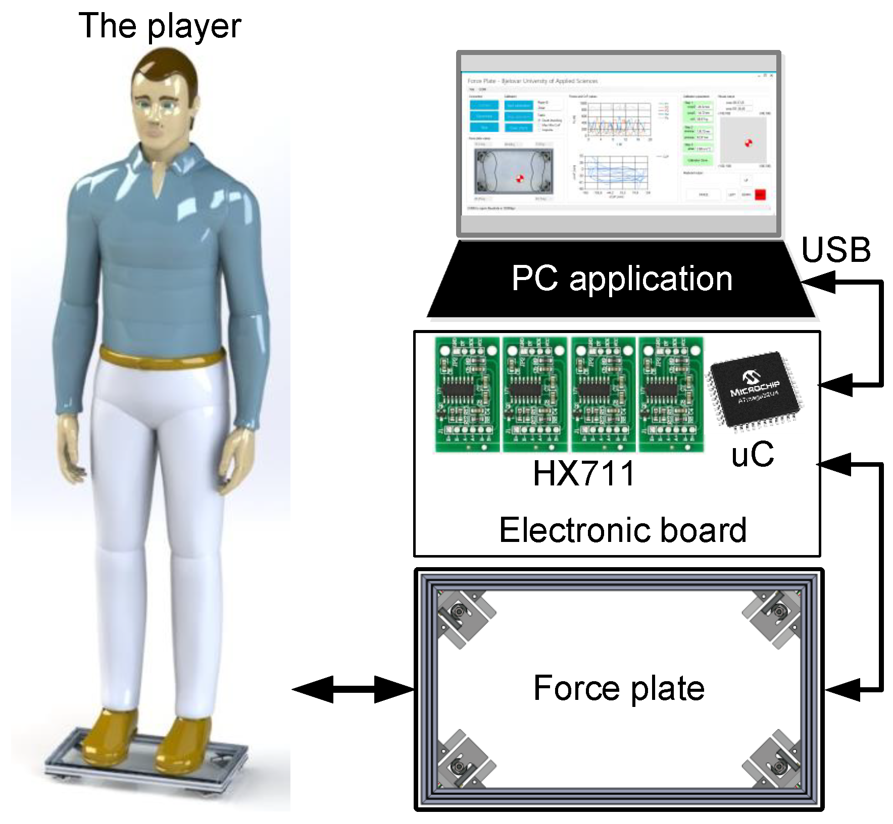
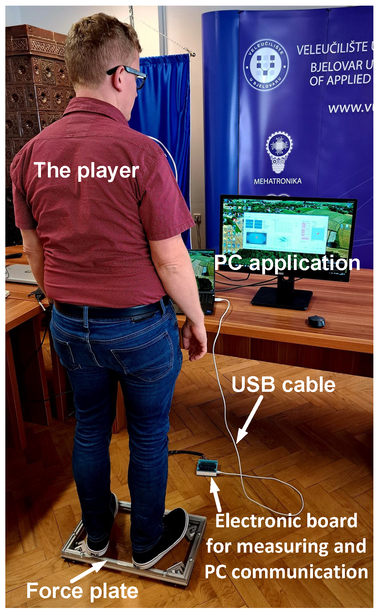
2. System Description

The game control system based on a force plate is shown in Figure 1, with its goal being to control games by utilizing changes in the player’s CoP and acceleration of the CoM along the z axis. Additionally, this system can also be used to analyze human balance and postural stability without any additional modifications. The system shown in Figure 1 consists of a force plate, an electronic board used for measuring and PC communication, and a PC application for data acquisition, system calibration, and game control.
The force plate contains four load cells which are used to calculate the position of the CoP and the acceleration of the CoM of the human body along the z axis. The electronic board for measuring and PC communication conducts the force measurement procedure with the help of the load cells and then processes the data and sends the data in the form of a data frame every 100 ms to the PC via USB communication. The PC application for data acquisition, system calibration, and game control receives the data frame, which contains information about the forces measured at the load cells, presents the data, logs it into a textual file for later analysis, conducts the system calibration individually for each player, and finally simulates the keyboard key press or mouse cursor movement or left click, all with the goal of controlling games.
The game control system is used as follows. The player stands on the force plate with both feet so that they do not step out of the force plate frame. After that, the system calibration is carried out in three steps. In the first step, the player stands still on the force plate so as to measure the initial position of the CoP, as well as the player’s mass. By measuring these parameters, the system adapts to the player’s local coordinate system so that they can control the game. In the next step, the player moves his or her CoM to establish the boundaries within which the CoP can move. With this step, scaling parameters are set for the shift in the position of the CoP within the given ranges; that is, the work plane of the player is defined. In the third step, the player’s CoM acceleration along the z axis is measured by performing impulse half squats. This is a state where the human body generates a ground reaction force through muscles along the z axis without performing a jumping motion. By measuring the acceleration of the player’s CoM along the z axis, a threshold is determined at which pressing the SPACE keyboard key or a left mouse button click will be simulated.
After the system is calibrated, it is ready to be used to control games. During the game, the PC application calculates the position of the human body’s CoP and acceleration of the CoM along the z axis. Based on the calculated values, it simulates pressing the UP, DOWN, LEFT, RIGHT, and SPACE keyboard keys or movements of the cursor and clicking the left mouse button. This is what enables controlling games using the player’s CoP and the acceleration of the player’s CoM along the z axis. The developed and constructed prototype of the system for game control based on a force plate with a player is shown in Figure 2. The image shows all the described parts of the system.

3. Mathematical Model of the System
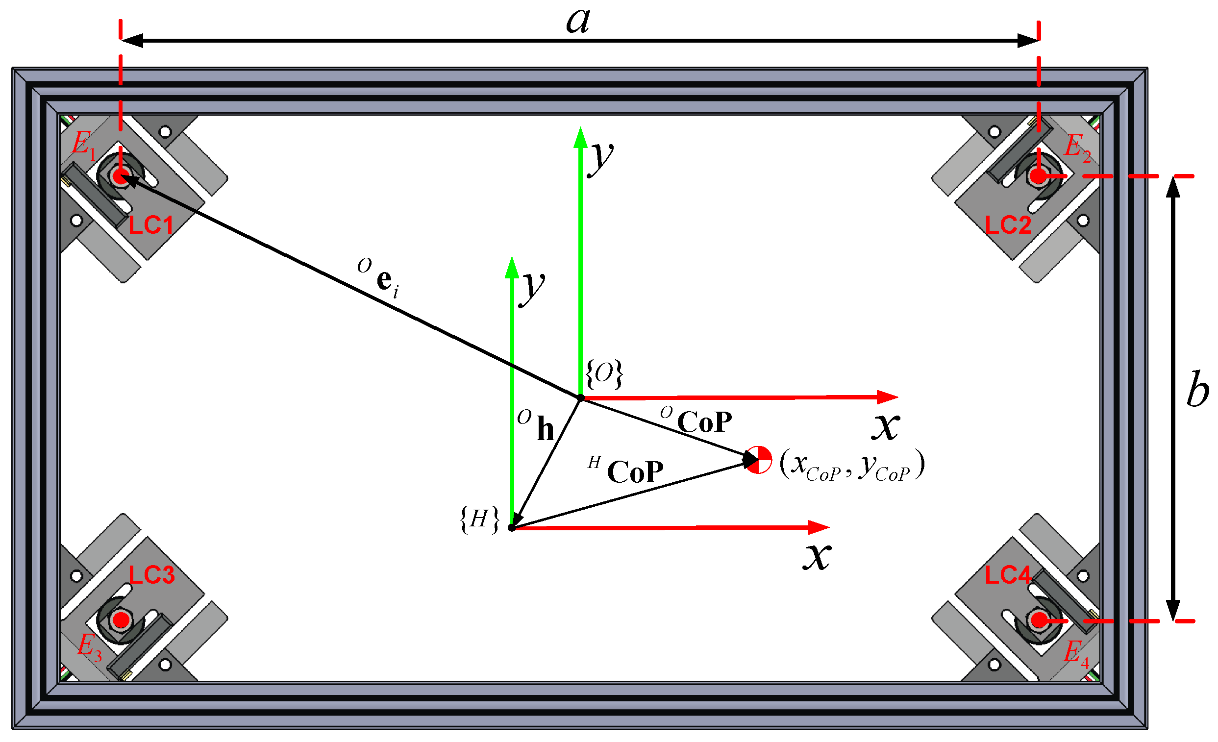
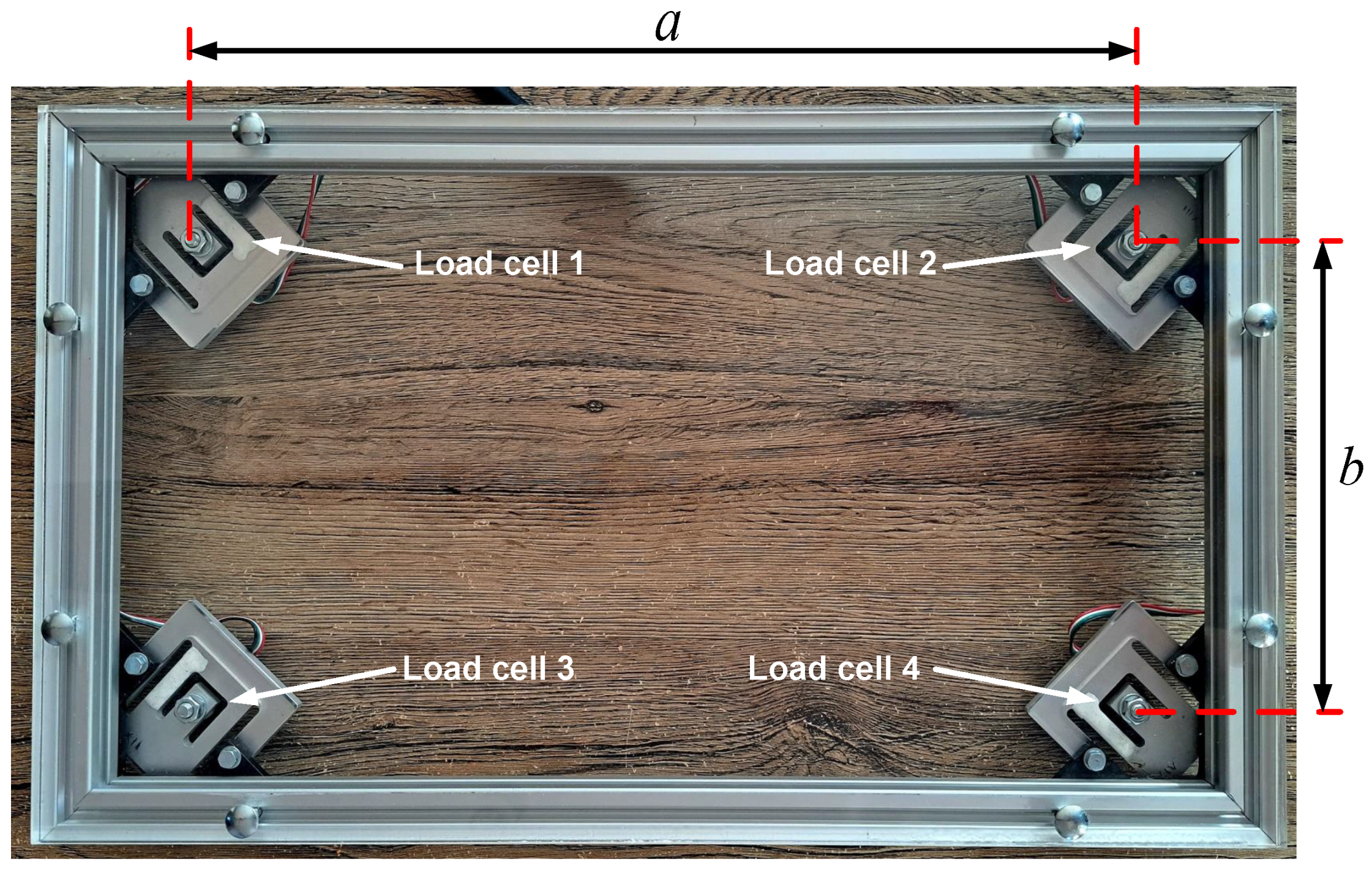
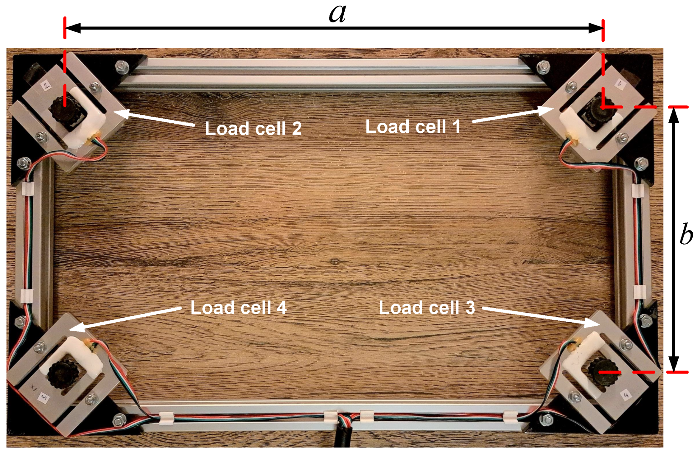
3.1. Force Plate

When the player is standing firmly on the base, while moving his or her body, the CoM changes. It is not possible to measure a player’s CoM, and thus an assessment of the player’s CoM is made using their CoP. A change in the player’s CoM causes a change in the CoP in the transverse plane [15,16]. This is how changing the position of a player’s CoM can generate analog or digital signals that are equivalent to the signals generated by a keyboard or mouse for the purpose of controlling a game. In this paper, for the purposes of calculating the position of the human body’s CoP, a force plate is used that measures the reaction of the base and the feet. The geometry of the force plate is shown in Figure 3. The force plate has four load cells used for force measuring. They are located in the corners of the force plate, and they are indicated with LC1, LC2, LC3, and LC4.
Two frames are shown in Figure 3: the global frame of the force plate {O} and the local frame of the human body (player) in quiet standing {H}. The parameters for CoP measurement shown in Figure 3 are the following:
  • a: the distance between the load cells along the x axis;
  • b: the distance between the load cells along the y axis;
  • O h : the position vector of a local frame {H} in the global frame {O};
  • O e i : the position vector of the ith load cell in the global frame {O};
  • O CoP 
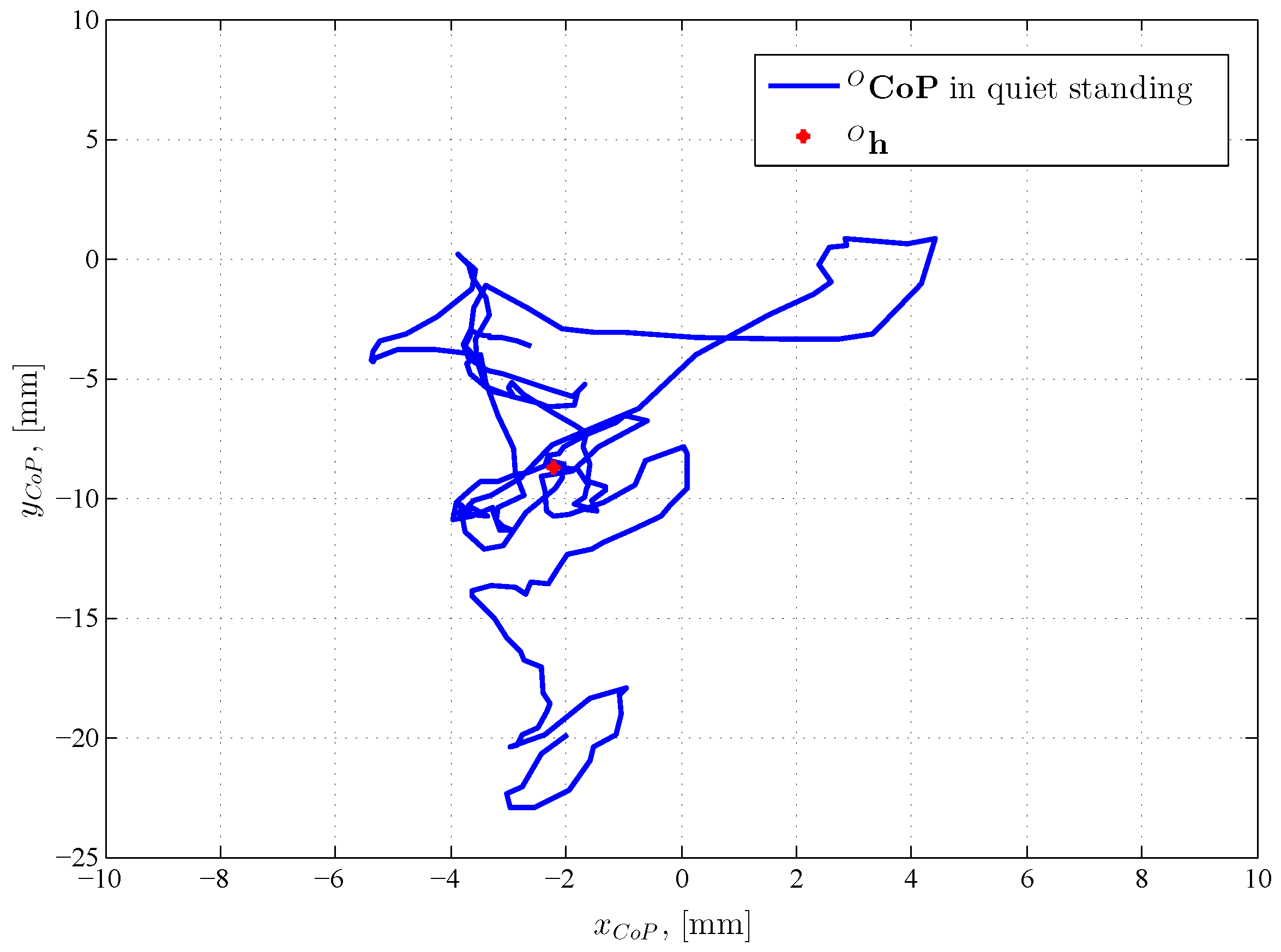
: the position vector of the player’s CoP in the global frame {O};
  • H CoP : the position vector of the player’s CoP in the global frame {H}.
The position vector O e i ( i = 1 , 2 , 3 , 4 ) of each individual load cell in the global frame {O} can be expressed as follows:
O e 1 = a 2 b 2 , O e 2 = a 2 b 2 , O e 3 = a 2 b 2 , O e 4 = a 2 b 2
In the global frame {O}, the position vector of the player’s CoP can be calculated according to the following relation [6,9]:
O CoP = x C o P y C o P = 1 i = 1 4 F i i = 1 4 e i F i ,
where F i ( i = 1 , 2 , 3 , 4 ) are the forces measured by the ith load cell. The sum of the F i ( i = 1 , 2 , 3 , 4 ) forces represents the ground reaction force, which can be calculated as follows:
F z = i = 1 4 F i
According to Equations (1)–(3), the coordinates of the player’s CoP in the global frame {O} are
x C o P = a 2 F 1 + F 2 F 3 + F 4 F z
y C o P = b 2 F 1 + F 2 F 3 F 4 F z
Due to various anthropometric parameters of the human body, it is not realistic to expect that the starting CoP of a player who is standing upright and still on the force plate is also going to be in the origin of frame {O}. Thus, the system needs to be adapted to the various CoP starting positions of an upright and still player on the force plate. Generating reference values for the key press or mouse click simulation via the force plate cannot depend on how the player was originally positioned on the force plate. In order to achieve this, the player’s coordinate system needs to be placed in the origin of the {H} frame (i.e., in the original position of the CoP of a player standing upright and quiet on the force plate). In the local frame {H}, the relevant position vector of the player’s CoP can be calculated according to the following expression [5,17]:
H CoP = H x C o P H y C o P = O CoP O h = x C o P y C o P x C o P 0 y C o P 0
The O h position vector represents the initial CoP of the upright and still player on the force plate in the frame {O}. The player’s CoP position determined via Equation (6) is used to manage movements in games by simulating keyboard key pressing or mouse cursor movement. For additional game controls, such as pressing the SPACE key or clicking the left mouse button, an impulse half squat needs to be detected on the force plate. If the player on the force plate performs such a movement, then the acceleration of the CoM of the player on the z axis changes. According to Newton’s second law, the following is valid [18,19,20]:
m H z ¨ C o M = F z m H g ,
where m H is the player’s mass, z ¨ C o M is the acceleration of the player’s CoM along the z axis, and g is the gravitational acceleration. When the human body is standing upright and quiet, the ground reaction force F z is equal to the body weight, and the CoM acceleration along the z axis amounts to 0 m/s 2 . When performing an impulse half squat, the acceleration z ¨ C o M will show changes in the signal (local signal maximums). Through detecting the local signal maximums z ¨ C o M , pressing the SPACE key on the keyboard or clicking the left mouse button can be simulated.

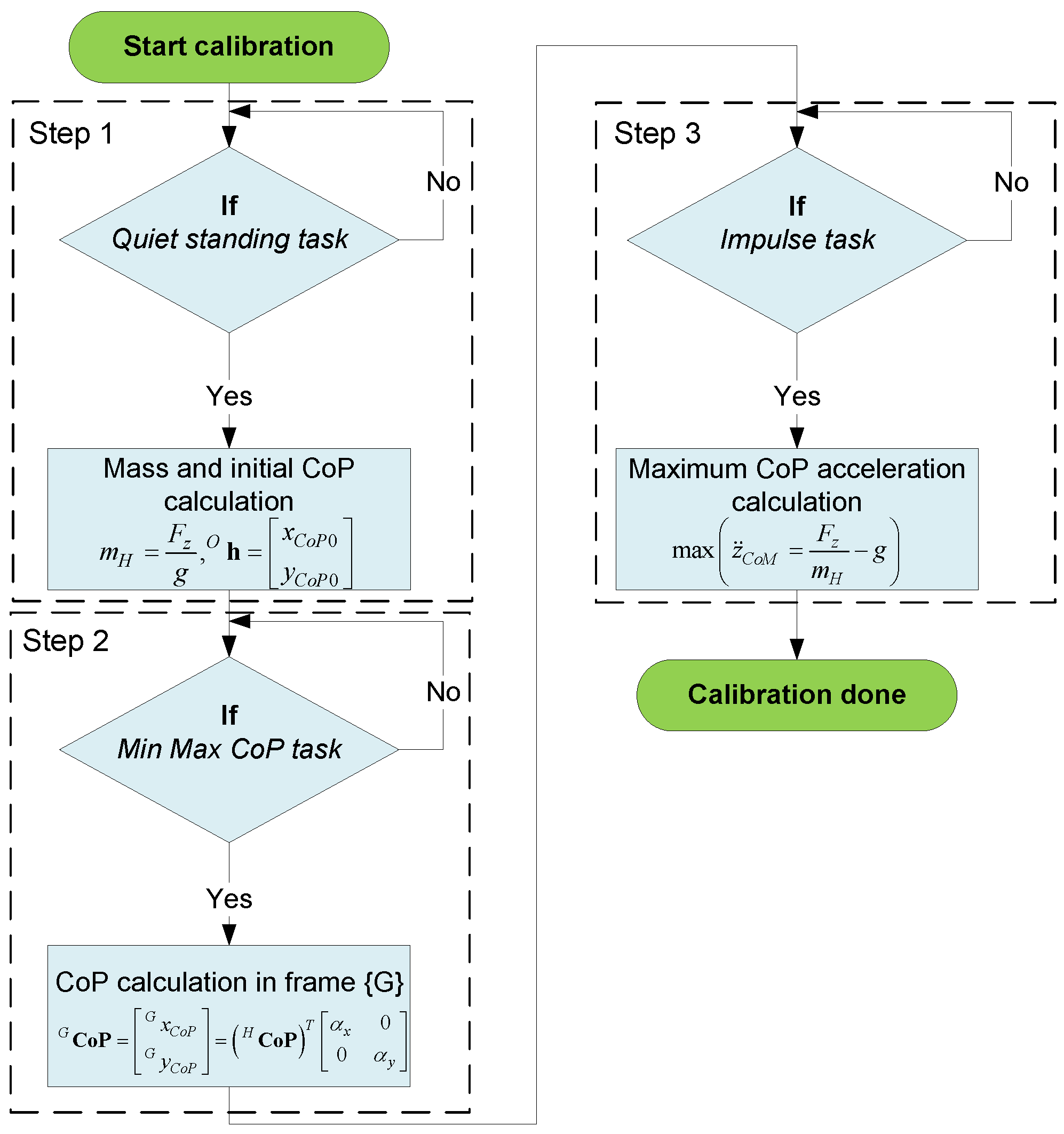
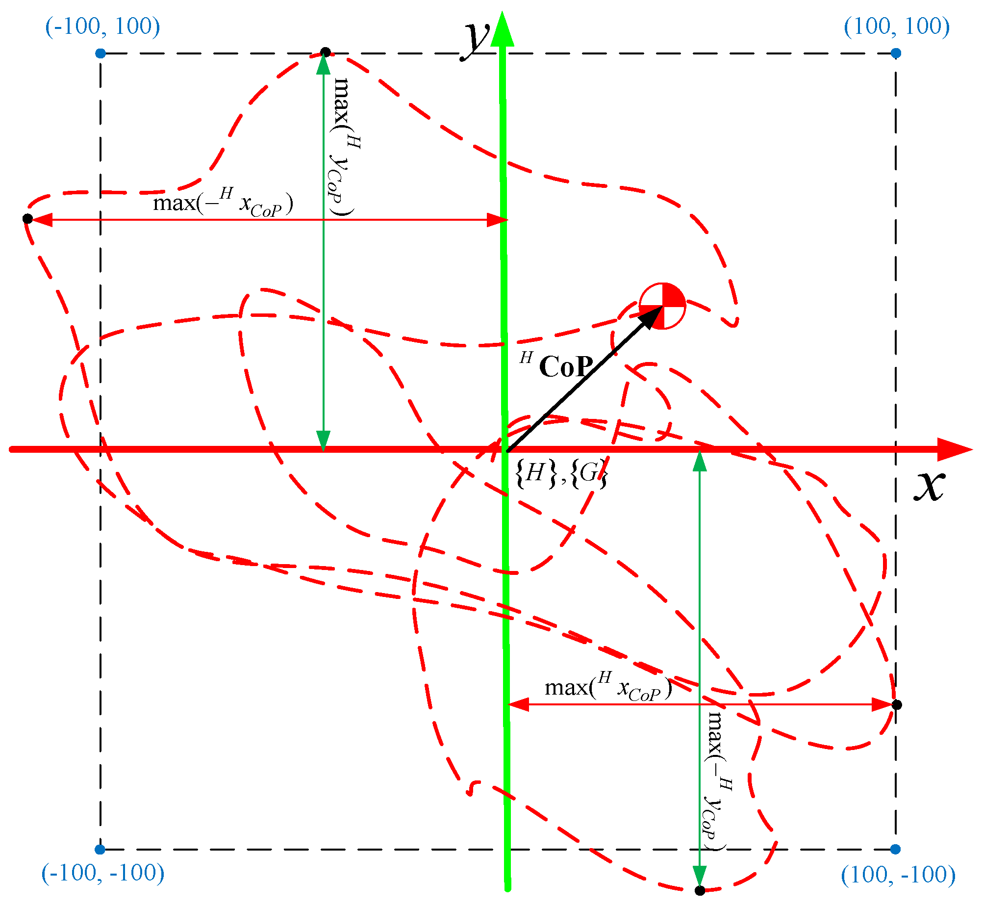
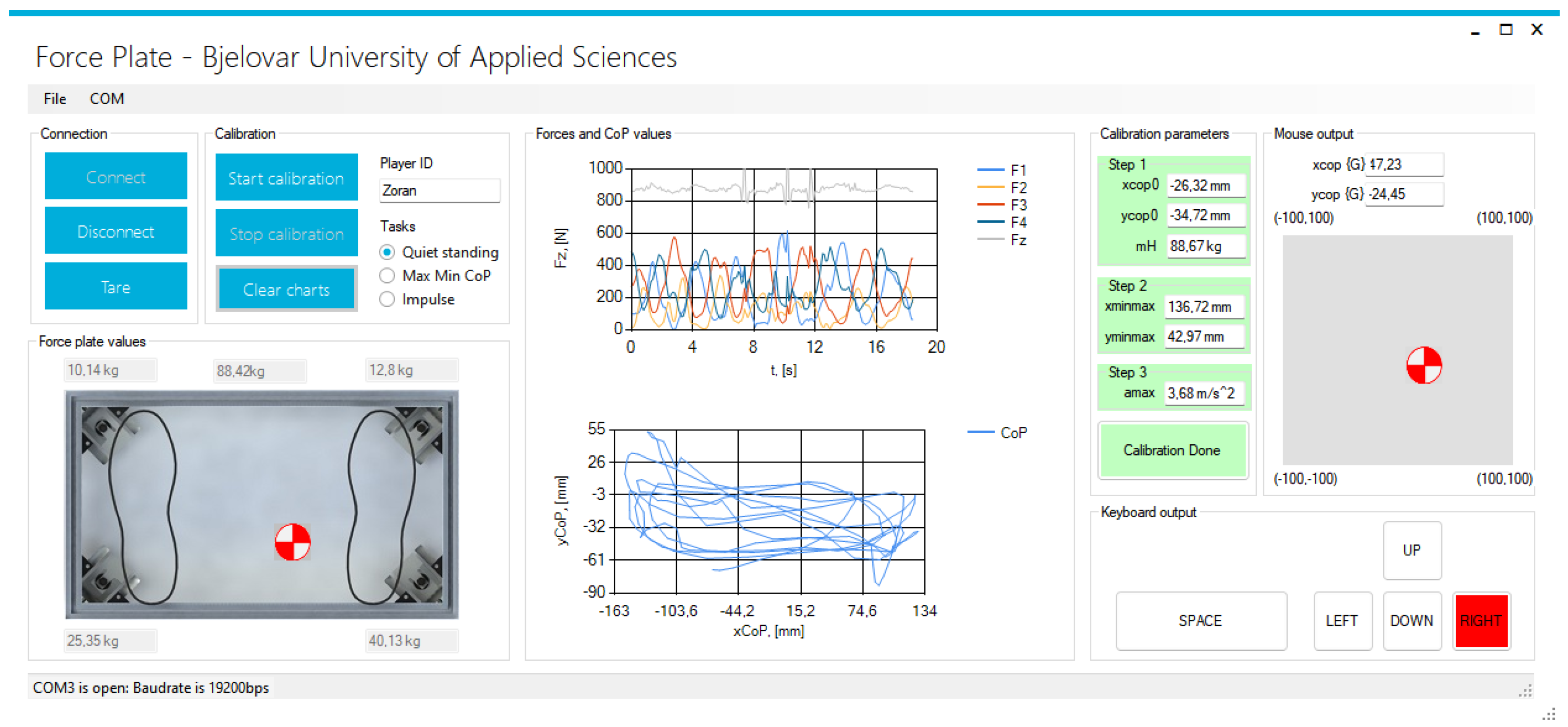
3.2. System Calibration and Game Control

Before using the system for game control based on a force plate, an individualized calibration of the system needs to be conducted for each player. The goal of the calibration process is to adapt the system to the player so that the player can have the best possible experience controlling the game. The calibration procedure of the system for game control based on a force plate is shown in Figure 4.
The calibration procedure is conducted in three steps. In the first step of the calibration (Step 1 in Figure 4), the player standing on the force plate must maintain an upright and still standing during the ground reaction force measurements. After 20 s, measuring is complete, and the player’s mass is calculated according to Equation (7) ( z ¨ C o M 0 m/s 2 ):
m H = 1 N i = 1 N F z i g ,
where N is the number of measured instances of the F z force on the load cells. The position vector of the initial player’s CoP O h is calculated as the mean value of the CoP measurements according to Equations (4) and (5) during the 20 s of measuring as follows:
O h = x C o P 0 y C o P 0 = 1 N i = 1 N x C o P i 1 N i = 1 N y C o P i
The result of the first calibration step is the player’s mass m H and the initial player CoP position O h in the local frame {H}. In the second step of the calibration process, the player moves his or her CoM so as to reach the maximum CoP deviations along the x and y axes on the force plate in the local frame {H}. While conducting the second step (Step 2 in Figure 4), which takes 20 s, the player receives visual feedback on the position of his or her CoP in the PC application. The result of the second step is the identification of the player’s work plane. Searching for the player’s work plane is shown in Figure 5. The maximum player CoP deviations during the execution of the second calibration step along the x and y axes are as follows:
  • max ( H x C o P ) 
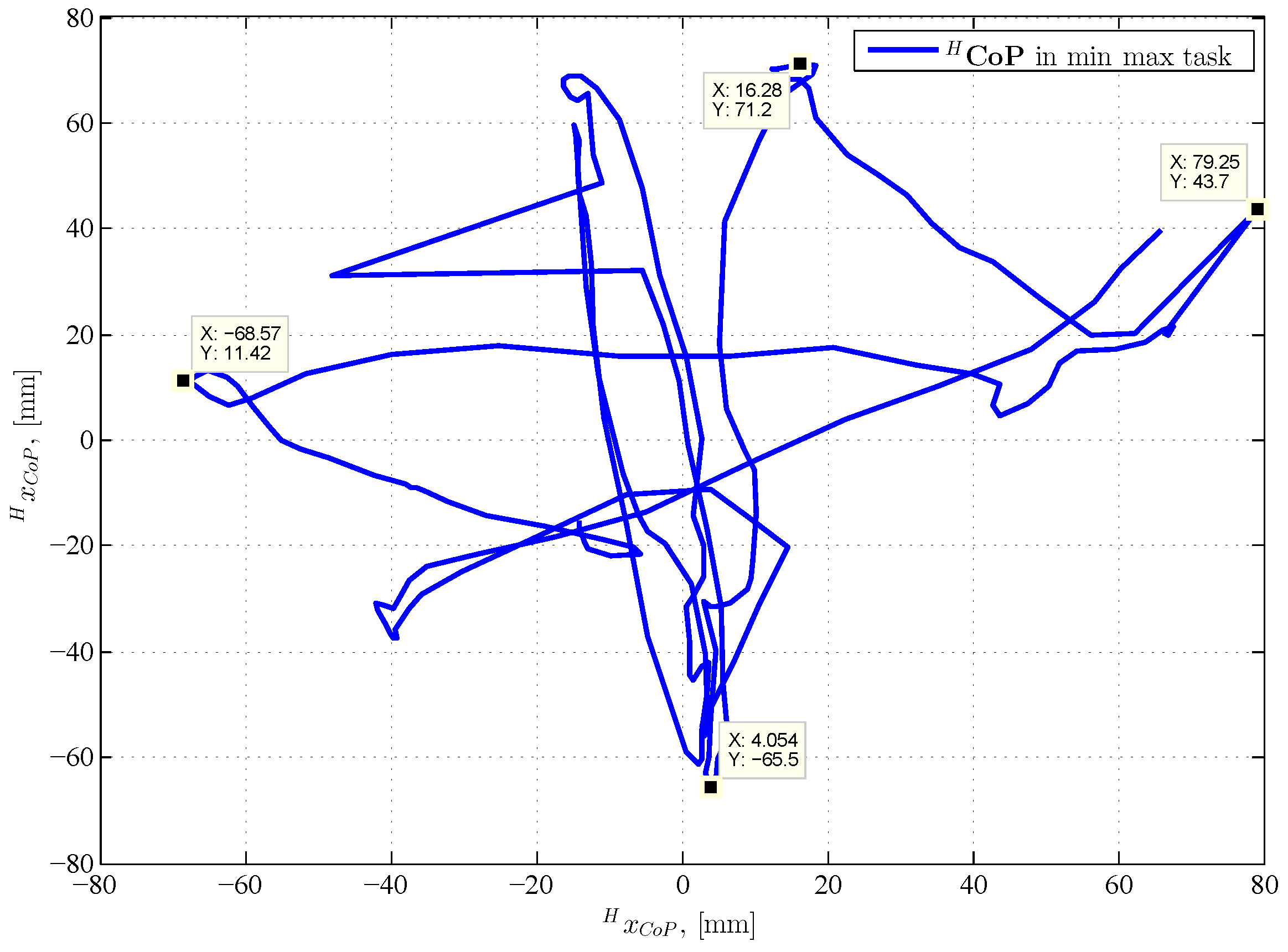
: the maximum distance of the player’s CoP position from the origin along the positive x axis;
  • max ( H x C o P ) : the maximum distance of the player’s CoP position from the origin along the negative x axis;
  • max ( H y C o P ) : the maximum distance of the player’s CoP position from the origin along the positive y axis;
  • max ( H y C o P ) : the maximum distance of the player’s CoP position from the origin along the negative y axis.
Figure 5. Searching for the work plane on the force plate and scaling the work plane into the local frame {G}.
Applsci 13 11753 g005
The smallest maximum distances of the player’s CoP position along the positive and negative x and y axes represent the borders of the player’s work plane (see Figure 5) such that the player is able to reach every point of the work plane, (i.e., every point on the game screen). Based on the example in Figure 5, the smallest maximum distance from the origin along the positive and negative x axis is max ( H x C o P ) .
The position of the CoP in the local frame {H} needs to be transferred into the local frame {G}, which is the local frame that controls the game. The player’s CoP in the local frame {G} can be calculated as follows:
G CoP = G x C o P G y C o P = α x 0 0 α y H CoP ,
where the following are true:
  • G x C o P 
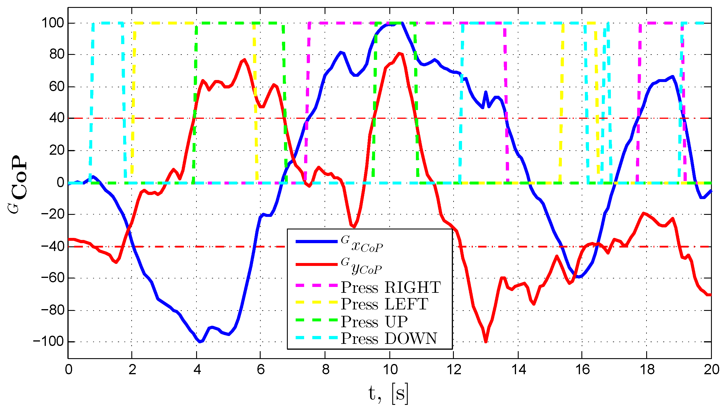
is the player’s CoP position in the local frame {G} along the x axis in the [−100, 100] range;
  • G y C o P is the player’s CoP position in the local frame {G} along the y axis in the [−100, 100] range;
  • α x is the factor of the player’s CoP position transformation along the x axis from the local frame {H} into the [−100, 100] range of the local frame {G};
  • α y is the factor of the player’s CoP position transformation along the y axis from the local frame {H} into the [−100, 100] range of the local frame {G}.
The variables G x C o P and G y C o P are limited within the [−100, 100] range. Based on all this, the linear transformation factor α x is calculated as follows:
α x = 100 min ( max ( H x C o P ) , max ( H x C o P ) )
The linear transformation factor α y is calculated as follows:
α y = 100 min ( max ( H y C o P ) , max ( H y C o P ) )
The denominators in Equations (11) and (12) are the smallest maximum distances of the player’s CoP position along the positive and negative x and y axes. After finishing the second step of the calibration process, the changes in the player’s CoP are scaled into the [−100, 100] range along the x and y axes. If there is a need to scale the player’s CoP position into a different range (such as a range defined by the screen resolution), then Equation (10) can be transformed into a new local frame via a linear transformation.
In the third step of the calibration (Step 3 in Figure 4), the player performs impulse half squats on the force plate during 20 s. For each detected half squat, a maximum of the acceleration function of the player’s CoM along the z axis is determined. The acceleration function is calculated from Equation (7) by dividing the whole equation by m H . The result of the third calibration step is a number of local maximums of the CoM acceleration function along the z axis, with which we can determine the threshold for pressing the SPACE key or clicking the left mouse button.
Having completed the described calibration procedure for the game control system, as shown in Figure 4, the next step is defining the conditions under which the pressing of keyboard keys or moving the mouse cursor would be simulated for the purpose of game control. The system is set up in such a way to simulate pressing the UP, DOWN, RIGHT, LEFT, and SPACE keys or to move the mouse cursor and click the left mouse button. Table 1 shows the conditions under which pressing the defined keyboard keys is performed. The individual buttons will be pressed if the player’s CoP in the local frame {G} is greater (or rather lower) than the defined threshold along the positive or negative x and y axis. Table 1 defines the following thresholds:
  • y T H : the threshold for pressing the UP and DOWN keys;
  • x T H : the threshold for pressing the RIGHT and LEFT keys;
  • a T H 
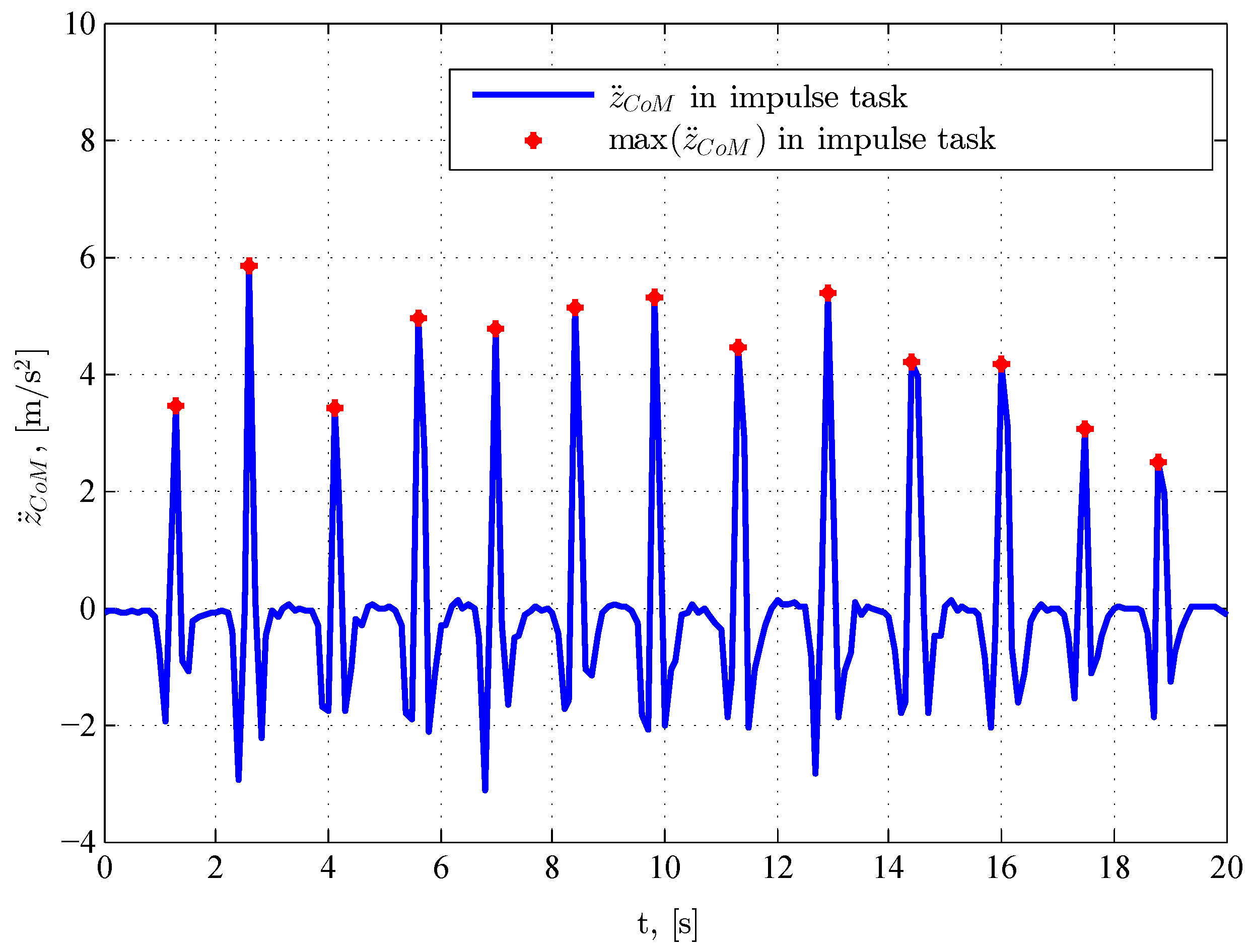
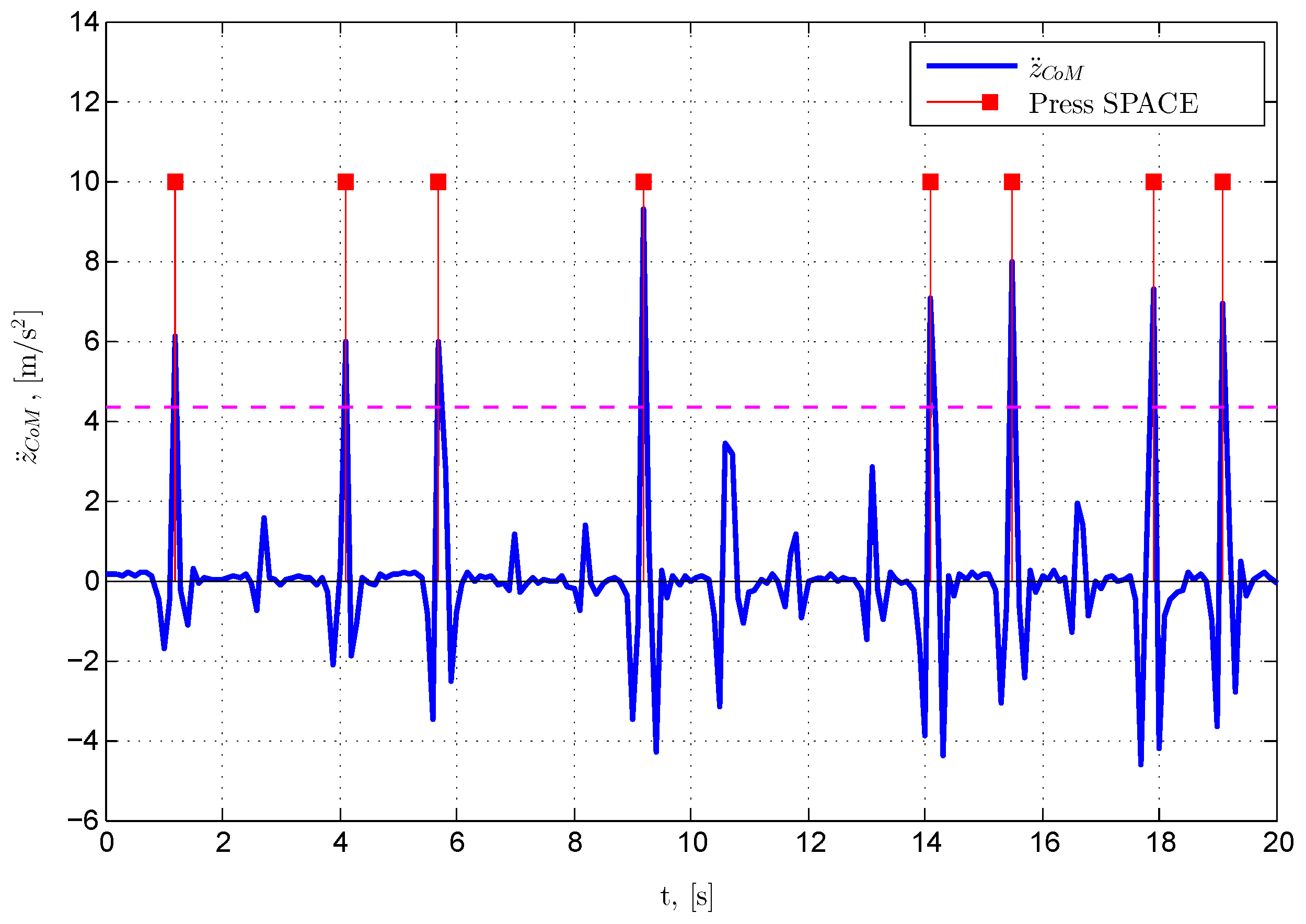
: the threshold for pressing the SPACE key.
Table 1. Conditions for pressing a key on the keyboard.
Condition for Pressing a KeyTrue ConditionFalse Condition
if ( G C o P y > y T H )Press UPRelease UP
if ( G C o P y < y T H )Press DOWNRelease DOWN
if ( G C o P x > x T H )Press RIGHTRelease RIGHT
if ( G C o P x < x T H )Press LEFTRelease LEFT
if ( z ¨ C o M > a T H )Press LEFTRelease LEFT
For example, if the player’s CoP position along the y axis in the local frame {G} G y C o P is greater than y T H , then the system will simulate pressing the UP key, and if it is lower, then it will stimulate releasing the UP key. The same y T H threshold is used for the DOWN key but with a negative sign (minus). The x T H and y T H thresholds in Table 1 can be defined empirically through conducted experiments. The a T H threshold can be defined, as mentioned, by measuring the local maximums of the function of CoM acceleration along the z axis. The criterion for defining the a T H threshold can be a mean or median value of all the measured maximums of the function of CoM acceleration along the z axis.
Controlling games by using mouse cursor movements and left mouse button clicking is performed in a different way compared with using just the keyboard, as shown in Table 1. Table 2 shows the conditions for clicking the left mouse button, and it is equivalent to the condition for pressing the SPACE key.
Movement of the mouse cursor is simulated using the player’s CoP position in the local frame {G} by linearly transforming the CoP position into the mouse cursor position on screen, as shown by the following expression:
x m o u s e y m o u s e = X R E S 200 0 0 Y R E S 200 G CoP + X R E S 2 Y R E S 2
where the following are true:
  • x m o u s e 
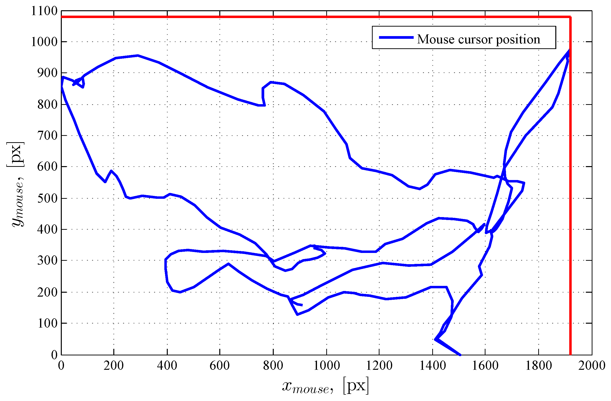
is the mouse cursor position along the x axis;
  • y m o u s e is the mouse cursor position along the y axis;
  • X R E S is the horizontal screen resolution;
  • Y R E S is the vertical screen resolution.
In Equation (13), aside from scaling the CoP position, a translation of the {G} origin into the screen origin has been carried out, which is in the lower left corner.
According to the derived mathematical model for the game control system, the force plate measures the player’s CoP position in the frame {O}, which is shown in the local frame {H} via the relation in Equation (6). The CoP position in the local frame {H} is translated into the CoP position in the local frame {G} with the help of the relation in Equation (10). Depending on the CoP values in the local frame {G}, a decision is made for pressing the UP, DOWN, RIGHT, and LEFT keyboard keys or moving the mouse cursor. Detecting the acceleration of the player’s CoM along the z axis, which is caused by performing impulse half squats, is used to control pressing the SPACE keyboard key or clicking the left mouse button. To conclude, changing the player’s CoP and accelerating the player’s CoM along the z axis enables the simulation of pressing the UP, DOWN, RIGHT, LEFT, and SPACE keyboard keys or moving the mouse cursor and clicking the left mouse button to enable controlling games.

4. Mechatronic System Design

4.1. Mechanical Design

The force plate in Figure 6 is made according to the designed CAD model. The force plate frame is made of aluminum angles (20 × 20 mm) with a 10 mm thick acrylic sheet attached to it. The force plate dimensions are 480 × 280 × 45 mm. Using angles, the load cells are secured to the corners of the aluminum frame. The distance between the load cells along the x axis is a = 388 mm, and along the y axis, it is b = 188 mm. Figure 7 shows the bottom side of the force plate, where legs adjustable for height are visible and which are used as a basis for the force plate.

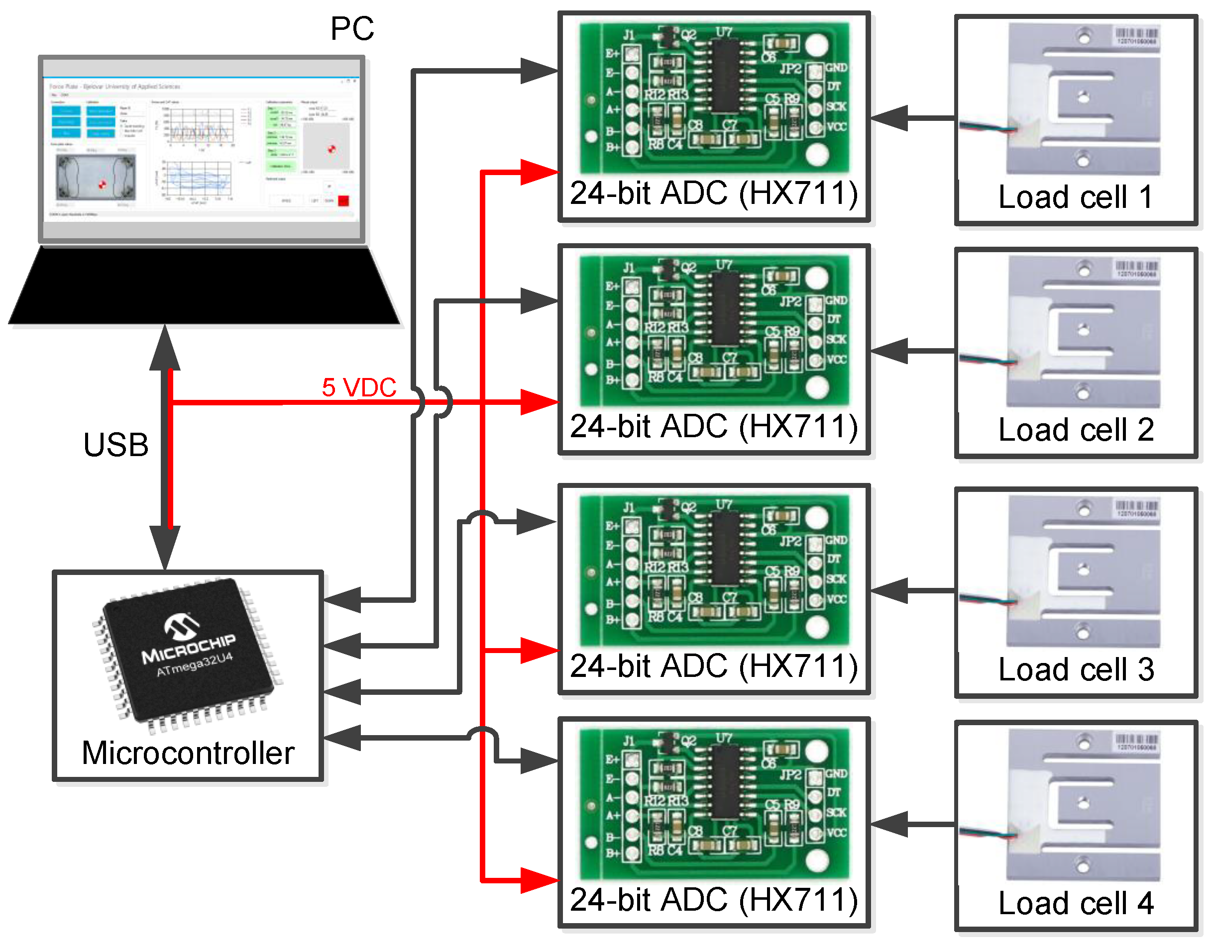
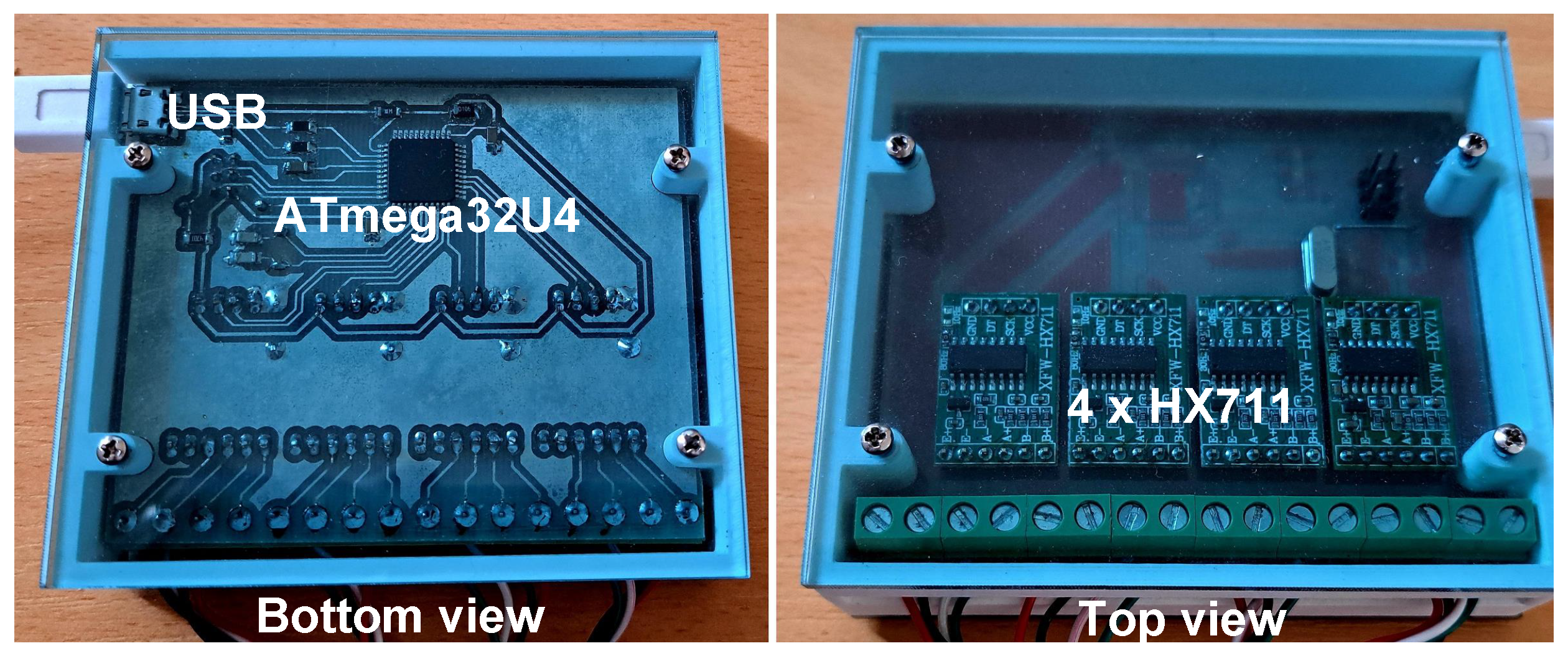
4.2. Electronic Design

The electronic architecture of the system for game control is shown in Figure 8. It consists of an ATmega32U4 microcontroller with necessary periphery components, four analog-digital (AD) HX711 transformers, four load cells, and a PC with an application for data acquisition, system calibration, and game control.
The electronic board for measuring and PC communication is shown in Figure 9. The ATmega32U4 microcontroller is connected to the PC via a USB connection. The power supply is secured through a USB connection with the PC. Force measurements are conducted by using the load cells (part number L6P-C3-45kg), which generate a voltage proportional to the measured force [21]. The generated voltage is sampled with a 10 Hz frequency using an HX711 AD converter and is then amplified 128 times and converted into a digital word.
The HX711 AD converters are connected to the ATmega32U4 microcontroller with two digital pins. For a total of four load cells, eight ATmega32U4 microcontroller digital pins are used. Force measurement is carried out with all four load cells simultaneously. Each of the four load cells are calibrated prior to use by employing known mass calibration weights of 200 g, 500 g, 700 g, and 1000 g. A load cell is a linear measurement element, and thus the dependency of the known measured force on the result of the AD conversion will be linear. The force measured by the load cell i can be calculated according to the following relation [22]:
F i = k i A D C L C i T A R E i
where the following are true:
  • k i is the calibration coefficient of the ith load cell;
  • A D C L C i is the conversion value of the HX711 AD converter, which is connected to the ith load cell;
  • T A R E i is the value of the force measured by the unladen ith load cell.
The calibration coefficients k i are calculated through the procedure described in [23] and shown in Table 3.

4.3. Software Design

4.3.1. Firmware for ATmega32U4 Microcontroller

The ATmega32U4 microcontroller software was developed in the Microchip Studio development environment in the C programming language. When connecting a force plate to a computer using a USB cable, the ATmega32U4 microcontroller runs an initialization of the microcontroller and load cell tare procedure. The tare procedure calculates the value of the TAREi force, which is measured by the unladen ith load cell. After initializing the microcontroller and taring the load cells, individual F 1 , F 2 , F 3 , and F 4 load cell measurements are sent by the ATmega32U4 microcontroller to the PC via a USB connection in form of a data frame once every 100 ms.

4.3.2. PC Application for Data Acquisition, System Calibration, and Game Control

The PC application for data acquisition, system calibration, and game control is shown in Figure 10, and it was built in the .NET framework and written in C#. The application uses USB communication to fetch the force measurements from the force plates via the ATmega32U4 microcontroller. The app uses the measured forces to calculate and present the player’s CoP in the various frames. The calibration process of the system shown in Figure 4 is performed by the application. Each new system calibration step is started with the “Start calibration” button. While running the calibration steps, the app stores the measured forces in a textual file so that the data can be processed later. Each calibration step can be repeated multiple times. After the system calibration is completed, the player standing on the force plate can change his or her CoM to simulate pressing the UP, DOWN, RIGHT, LEFT, and SPACE keyboard keys or mouse cursor movement or clicking the left mouse button, all with the purpose of controlling the game. The application enables the display of the simulation of pressing each individual key, which is accomplished by changing the color of the key in the user interface to red. The purpose of the application is the validation of the game control system. The system calibration, player CoP calculation, the calculation of the acceleration of the player CoM along the z axis, and simulating pressing keyboard buttons and moving the mouse cursor can also be carried out via the ATmega32U4 microcontroller after the system validation is conducted.

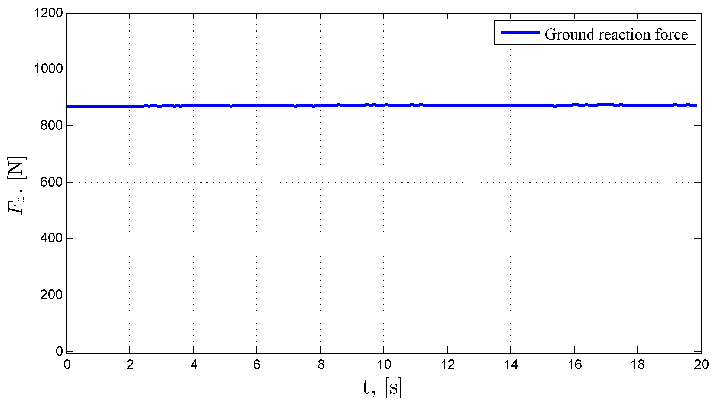
5. Results and Discussion

The goal of this experiment was the validation of the developed prototype of the system for game control based on a force plate. The calibration and work testing experiment on the game control system was conducted with one participant as the player (the article’s author) with prior consent.
The player stood with both of his feet on the force plate (see Figure 2) and was asked to stand quiet and upright for the next 20 s during the first step of the system calibration procedure. Figure 11 shows the player’s CoP measurement in frame {O} during quiet and upright standing.
The blue color shows the graph of the player’s CoP position during such standing in frame {O}. The red pluses show the average value of the player’s CoP (i.e., the O h position vector calculated based on Equation (9)). The components for the O h position vector were x C o P 0 = −2.21 mm and y C o P 0 = −8.73 mm. Figure 12 shows the ground reaction force measurement in frame {O} during quiet and upright standing. The average value of the ground reaction force on the graph was 871.23 N. According to the relation in Equation (8), the player’s mass was m H = 88.81 kg. The components of the O h position vector and the m H player mass were the results of the first step of the calibration procedure for the game control system.
While conducting the second system calibration step, the player was asked to move his body’s CoM during a 20 s period so as to reach the maximum CoP deviations along the x and y axes. The goal of this step was to find the player’s work plane. The searching for the player’s work plane is shown in Figure 13. The graph showing the CoP position in the local frame {H} shows the following parameters: max ( H x C o P ) = 79.25 mm, max ( H x C o P ) = 68.57 mm, max ( H y C o P ) = 71.20 mm, and max ( H y C o P ) = 65.50 mm.
The smallest maximum distances of the player’s CoP position from the origin and along the positive and negative x and y axes represent the borders of the player’s work plane (see Figure 5), which were found during the second calibration step. The graph from Figure 13 shows the following: min ( max ( H x C o P ) , max ( H x C o P ) ) = 68.57 mm and min ( max ( H y C o P ) , max ( H y C o P ) ) = 65.50 mm. Based on the aforementioned smallest maximum distances of the player’s CoP position from the origin, the linear transformation factors were calculated based on the relations in Equations (11) and (12). The result of the second system calibration step was presenting the player’s CoP position in the local frame {G}, which is also the frame used to control games.
In the third step of the system calibration procedure, the player was asked to perform impulse half squats on the force plate for 20 s. Figure 14 shows the player’s CoM acceleration measurements along the z axis during the performance of the impulse half squats. The blue color on the graph represents the player’s CoM acceleration along the z axis ( a m a x = z ¨ C o M ), while the red pluses show the maximum values of the player’s CoM acceleration along the z axis ( a m a x i ) while performing the impulse half squats. The graph in Figure 14 shows the following values: The lowest local acceleration maximum value was min ( a m a x i ) = 2.47 m/s 2 , while the global acceleration maximum value was max ( a m a x i ) = 5.84 m/s 2 . The mean value of all acceleration maximums amaxi was 4.35 m/s 2 , and the median was 4.46 m/s 2 . The result of the third calibration step was determining the threshold for initiating the simulation of pressing the SPACE key or clicking the left mouse button.
After the game control system was calibrated, it was ready to be used for testing. For the purpose of system testing, the following thresholds were used from Table 1 and Table 2: x T H = 40 , y T H = 40, and a T H = 4.35. The x T H and y T H thresholds were determined empirically (by conducing experiments), while the a T H threshold was the mean value of all the acceleration maximums found in the third calibration step. Figure 15 shows the simulation of pressing the RIGHT, LEFT, UP, and DOWN keyboard keys. Of note is that the player’s CoP in the local frame {G} was in the [−100, 100] range. The graph in Figure 15 shows that when G y C o P > 40 , pressing the UP key was simulated. If G y C o P < 40 , then pressing the DOWN button was simulated. This test shows that the system for game control correctly simulated pressing the RIGHT, LEFT, UP, and DOWN keyboard keys according to the conditions in Table 1.
Figure 16 shows the simulation of pressing the SPACE keyboard key. It is visible that pressing the SPACE key was only simulated when the player’s CoM acceleration along the z axis during an impulse half squat was greater than the defined threshold of 4.35 m/s 2 . Furthermore, the impulse half squats that had an acceleration of less than 4.35 m/s 2 did not trigger the defined threshold, and in those cases, pressing the SPACE key was not simulated. This test shows that the system for game control correctly simulated pressing the SPACE keyboard key according to the conditions in Table 1.
Figure 17 shows a simulation of moving the mouse cursor on a screen with a horizontal resolution X R E S = 1920 and vertical resolution Y R E S = 1080. The red frame shows the screen size of 1920 × 1080 px. The transformation of the player’s CoP position in the local frame {G} to the screen local frame was carried out according to Equation (13). Of note is the fact that the cursor position moved within the defined screen resolution. The procedure used to trigger the simulation of clicking the left mouse button was the same as the process used for the SPACE key.
Figure 11, Figure 12, Figure 13, Figure 14, Figure 15, Figure 16 and Figure 17 show the successful calibration procedure of the system for game control based on a force plate. After successfully conducting the system calibration procedure, the system was ready to be used for the purpose of game control.
The system calibration and testing are also demonstrated in video form on YouTube [24]. The first part of the video shows the placement of the player on the force plate, followed by a successful calibration of the system for game control based on a force plate. Each system calibration step described in the diagram in Figure 4 resulted in parameters that were then used to control the game. The second part of the video shows successful control of a randomly chosen online game using a prototype of the game control system based on a force plate. The player who participated in the experiment rated the game experience as very good.

6. Conclusions

In this paper, a new system for game control is described which is based on measuring the player’s CoP and the CoM acceleration along the z axis using a force plate. Controlling the games is accomplished by simulating pressing the UP, DOWN, RIGHT, LEFT, and SPACE keyboard keys or moving the mouse cursor and clicking the left mouse button, all based on the measurements of the player’s CoP and CoM acceleration along the z axis. A mechatronic system was developed which consists of the following parts: a force plate used to measure the ground reaction force with load cells, an electronic board for measuring and PC communication via USB which processes the forces measured on the load cells, and a PC application used to gather the measured forces, calibrate the system, and control the games. A mathematical model of the fame control system was created which transferred the player’s CoP from the force plate frame into the local frame for game control. The main part of the mathematical model for the game control system is the system calibration procedure, which is used to adapt the system to each individual player so as to ensure the best player experience in game control. The calibration procedure is conducted in three steps. In the first calibration step, the system calculates the player’s mass and initial CoP position so that the game control will not depend on the way the player stands on the force plate. The next game control system calibration step enables finding the player’s work plane so that all possible key combinations or all mouse cursor positions can be enabled. The third calibration step conducts measurements of intensity of the impulse half squats with the goal of defining a trigger threshold for the simulation of pressing the SPACE key or clicking the left mouse button. It has been experimentally proven that the game control system can be successfully adapted to the player, allowing for a very good player experience when it comes to controlling games. Along with controlling games, the developed mechatronic system can also be used to control a variety of other objects, such as mobile robots, or it can be used to analyze human walking, balance, and postural stability.

Author Contributions

Conceptualization, Z.V. and G.B.; methodology, Z.V. and I.S.; software, Z.V., G.B., K.H. and I.S.; validation, Z.V., G.B. and K.H.; formal analysis, Z.V., K.H. and I.S.; writing—original draft preparation, Z.V.; writing—review and editing, Z.V.; visualization, Z.V. and G.B. All authors have read and agreed to the published version of the manuscript.

Funding

This research received no external funding.

Institutional Review Board Statement

Not applicable.

Informed Consent Statement

Informed consent was obtained from the one subject involved in the study.

Data Availability Statement

The data used in the study are available from the authors and can be shared upon reasonable request.

Conflicts of Interest

The authors declare no conflict of interest.

Abbreviations

The following abbreviations are used in this manuscript:
CADComputer-aided design
CoMCenter of mass
CoPCenter of pressure
PCPersonal computer
USBUniversal serial bus

References

  1. Palmieri, R.M.; Ingersoll, C.D.; Stone, M.B.; Krause, B.A. Center-of-pressure parameters used in the assessment of postural control. J. Sport Rehabil. 2002, 11, 51–66. [Google Scholar] [CrossRef]
  2. Riemann, B.L.; Guskiewicz, K.M.; Shields, E.W. Relationship between clinical and forceplate measures of postural stability. J. Sport Rehabil. 1999, 8, 71–82. [Google Scholar] [CrossRef]
  3. Quijoux, F.; Nicolaï, A.; Chairi, I.; Bargiotas, I.; Ricard, D.; Yelnik, A.; Oudre, L.; Bertin-Hugault, F.; Vidal, P.P.; Vayatis, N.; et al. A review of center of pressure (COP) variables to quantify standing balance in elderly people: Algorithms and open-access code. Physiol. Rep. 2021, 9, e15067. [Google Scholar] [CrossRef] [PubMed]
  4. Ruhe, A.; Fejer, R.; Walker, B. Center of pressure excursion as a measure of balance performance in patients with non-specific low back pain compared to healthy controls: A systematic review of the literature. Eur. Spine J. 2011, 20, 358–368. [Google Scholar] [CrossRef] [PubMed]
  5. Leach, J.M.; Mancini, M.; Peterka, R.J.; Hayes, T.L.; Horak, F.B. Validating and calibrating the Nintendo Wii balance board to derive reliable center of pressure measures. Sensors 2014, 14, 18244–18267. [Google Scholar] [CrossRef] [PubMed]
  6. Huang, C.W.; Sue, P.D.; Abbod, M.; Jiang, B.; Shieh, J.S. Measuring Center of Pressure Signals to Quantify Human Balance Using Multivariate Multiscale Entropy by Designing a Force Platform. Sensors 2013, 13, 10151–10166. [Google Scholar] [CrossRef] [PubMed]
  7. Zhu, Y. Design and Validation of a Low-Cost Portable Device to Quantify Postural Stability. Sensors 2017, 17, 619. [Google Scholar] [CrossRef] [PubMed]
  8. Vrhovski, Z.; Obrovac, K.; Nižetić, J.; Mutka, A.; Klobučar, H.; Bogdan, S. System for Evaluation and Compensation of Leg Length Discrepancy for Human Body Balancing. Appl. Sci. 2019, 9, 2504. [Google Scholar] [CrossRef]
  9. Eguchi, R.; Takahashi, M. Validity of the Nintendo Wii Balance Board for kinetic gait analysis. Appl. Sci. 2018, 8, 285. [Google Scholar] [CrossRef]
  10. Lange, B.; Flynn, S.; Chang, C.; Ahmed, A.; Geng, Y.; Utsav, K.; Xu, M.; Seok, D.; Cheng, S.; Rizzo, A. Development of an interactive rehabilitation game using the Nintendo WiiFit Balance Board for people with neurological injury. Top. Stroke Rehabil. 2010, 15, 345–352. [Google Scholar] [CrossRef] [PubMed]
  11. Baranyi, R.; Willinger, R.; Lederer, N.; Grechenig, T.; Schramm, W. Chances for serious games in rehabilitation of stroke patients on the example of utilizing the Wii Fit Balance Board. In Proceedings of the 2013 IEEE 2nd International Conference on Serious Games and Applications for Health (SeGAH), Vilamoura, Portugal, 2–3 May 2013; pp. 1–7. [Google Scholar] [CrossRef]
  12. Taylor, M.J.; McCormick, D.; Shawis, T.; Impson, R.; Griffin, M. Activity-promoting gaming systems in exercise and rehabilitation. J. Rehabil. Res. Dev. 2011, 48, 1171. [Google Scholar] [CrossRef] [PubMed]
  13. Ravenek, K.E.; Wolfe, D.L.; Hitzig, S.L. A scoping review of video gaming in rehabilitation. Disabil. Rehabil. Assist. Technol. 2016, 11, 445–453. [Google Scholar] [CrossRef] [PubMed]
  14. Park, D.S.; Lee, G. Validity and reliability of balance assessment software using the Nintendo Wii balance board: Usability and validation. J. Neuroeng. Rehabil. 2014, 11, 99. [Google Scholar] [CrossRef] [PubMed]
  15. Dos Santos, D.A.; Fukuchi, C.A.; Fukuchi, R.K.; Duarte, M. A data set with kinematic and ground reaction forces of human balance. PeerJ 2017, 5, e3626. [Google Scholar] [CrossRef]
  16. Lafond, D.; Duarte, M.; Prince, F. Comparison of three methods to estimate the center of mass during balance assessment. J. Biomech. 2004, 37, 1421–1426. [Google Scholar] [CrossRef] [PubMed]
  17. Cotton, S.; Vanoncini, M.; Fraisse, P.; Ramdani, N.; Demircan, E.; Murray, A.; Keller, T. Estimation of the centre of mass from motion capture and force plate recordings: A study on the elderly. Appl. Bionics Biomech. 2011, 8, 67–84. [Google Scholar] [CrossRef]
  18. Popovic, M.B. (Ed.) Copyright; Academic Press: Cambridge, MA, USA, 2019; p. iv. [Google Scholar] [CrossRef]
  19. Linthorne, N.P. Analysis of standing vertical jumps using a force platform. Am. J. Phys. 2001, 69, 1198–1204. [Google Scholar] [CrossRef]
  20. Lake, J.; Mundy, P.; Comfort, P.; McMahon, J.J.; Suchomel, T.J.; Carden, P. Concurrent Validity of a Portable Force Plate Using Vertical Jump Force–Time Characteristics. J. Appl. Biomech. 2018, 34, 410–413. [Google Scholar] [CrossRef] [PubMed]
  21. Muller, I.; de Brito, R.M.; Pereira, C.E.; Brusamarello, V. Load cells in force sensing analysis-theory and a novel application. IEEE Instrum. Meas. Mag. 2010, 13, 15–19. [Google Scholar] [CrossRef]
  22. Vrhovski, Z. Sustav za Procjenu i Kompenzaciju Razlike Duljina Nogu Radi Postavljanja Ljudskog Tijela u Ravnotežu. Ph.D. Thesis, University of Zagreb, Faculty of Electrical Engineering and Computing, Zagreb, Croatia, 2019. [Google Scholar]
  23. Benkek, G.; Vrhovski, Z.; Husak, K. Didaktičko učilo za kalibraciju senzora mase pomoću računala. Politeh. Dizajn. 2022, 10, 285793. [Google Scholar]
  24. Validation of a System for Game Control Based on Force Plate. Available online: https://www.youtube.com/watch?v=PMfpMvEPB-Y (accessed on 23 September 2023).
Figure 1. System for game control based on a force plate.
Applsci 13 11753 g001
Figure 2. Prototype of the system for game control based on a force plate.
Applsci 13 11753 g002
Figure 3. Geometry of the force plate.
Applsci 13 11753 g003
Figure 4. Calibration procedure of the system for game control based on a force plate.
Applsci 13 11753 g004
Figure 6. Parts of force plate: top view.
Applsci 13 11753 g006
Figure 7. Parts of force plate: bottom view.
Applsci 13 11753 g007
Figure 8. Electronic architecture of the system for game control.
Applsci 13 11753 g008
Figure 9. Electronic board for measuring and PC communication.
Applsci 13 11753 g009
Figure 10. PC application for data acquisition, system calibration, and game control.
Applsci 13 11753 g010
Figure 11. Measuring the player’s CoP in the frame {O} during quiet and upright standing (first system calibration step).
Applsci 13 11753 g011
Figure 12. Measuring the ground reaction force during quiet and upright standing (first system calibration step).
Applsci 13 11753 g012
Figure 13. Searching for the player’s work plane (second step of system calibration).
Applsci 13 11753 g013
Figure 14. Player CoM acceleration measurements along the z axis during the performance of impulse half squats (third step of system calibration).
Applsci 13 11753 g014
Figure 15. Simulating pressing the RIGHT, LEFT, UP, and DOWN keyboard keys.
Applsci 13 11753 g015
Figure 16. Simulating pressing the SPACE keyboard key.
Applsci 13 11753 g016
Figure 17. Simulation of moving the mouse cursor.
Applsci 13 11753 g017
Table 2. Conditions for clicking the left mouse button.
Condition for Clicking a ButtonTrue ConditionFalse Condition
if ( z ¨ C o M > a T H )Press Left Mouse ButtonRelease Left Mouse Button
Table 3. Calibration coefficient for force calculation using load cells.
Load Cell iCalibration Coefficient k i (N)
LC1212.09
LC2207.48
LC3204.24
LC4191.79
Disclaimer/Publisher’s Note: The statements, opinions and data contained in all publications are solely those of the individual author(s) and contributor(s) and not of MDPI and/or the editor(s). MDPI and/or the editor(s) disclaim responsibility for any injury to people or property resulting from any ideas, methods, instructions or products referred to in the content.

