
Analysis of the Design of Henry Muncaster’s Two-Cylinder Compound Vertical Steam Engine with Speed Control


Abstract
:1. Introduction
2. Materials and Methods
2.1. Operation of the Machine
2.2. Analysis from the Mechanical Engineering Standpoint
2.2.1. Preprocessing
- The fixing elements were excluded since they require a very fine mesh size and because there is a large number of this type of component. Thus, some of these elements (bolts and nuts) are replaced by a ‘bonded’ contact relationship, that is, by a welded joint. However, it must be taken into account that a welded connection is more rigid than a connection using bolts and nuts, so if critical stress values occur in an area where a fastening element should go or in the contact area, then those initially excluded elements must be included.
- The centrifugal speed regulator was excluded since its operation is basically dynamic, so it does not make any sense to carry out a static linear analysis of this subset. In addition, the critical conditions to be simulated are from the machine stop or start-up conditions, for which the centrifugal speed regulator does not have any angular velocity.
2.2.2. Assignment of Materials
2.2.3. Application of Contacts
- ‘Bonded’ type: This type of contact represents a welded joint, thus preventing relative movement between the nodes of the meshes of the solids in contact with each other.
- ‘Surface’ type: This represents the most common contact between two solids. With this type of contact, the relative movement between the nodes of the meshes in contact is allowed. To better understand this type of contact, it can be compared to the sliding of an object on a surface with a certain coefficient of friction.
- Symmetric contact: The nodes of the mesh of a solid cannot penetrate the mesh of the other solid in contact with it and vice versa.
- Unsymmetrical contact: For this case, the nodes of the mesh of one solid can penetrate the mesh of the opposite solid in contact with it, and vice versa.
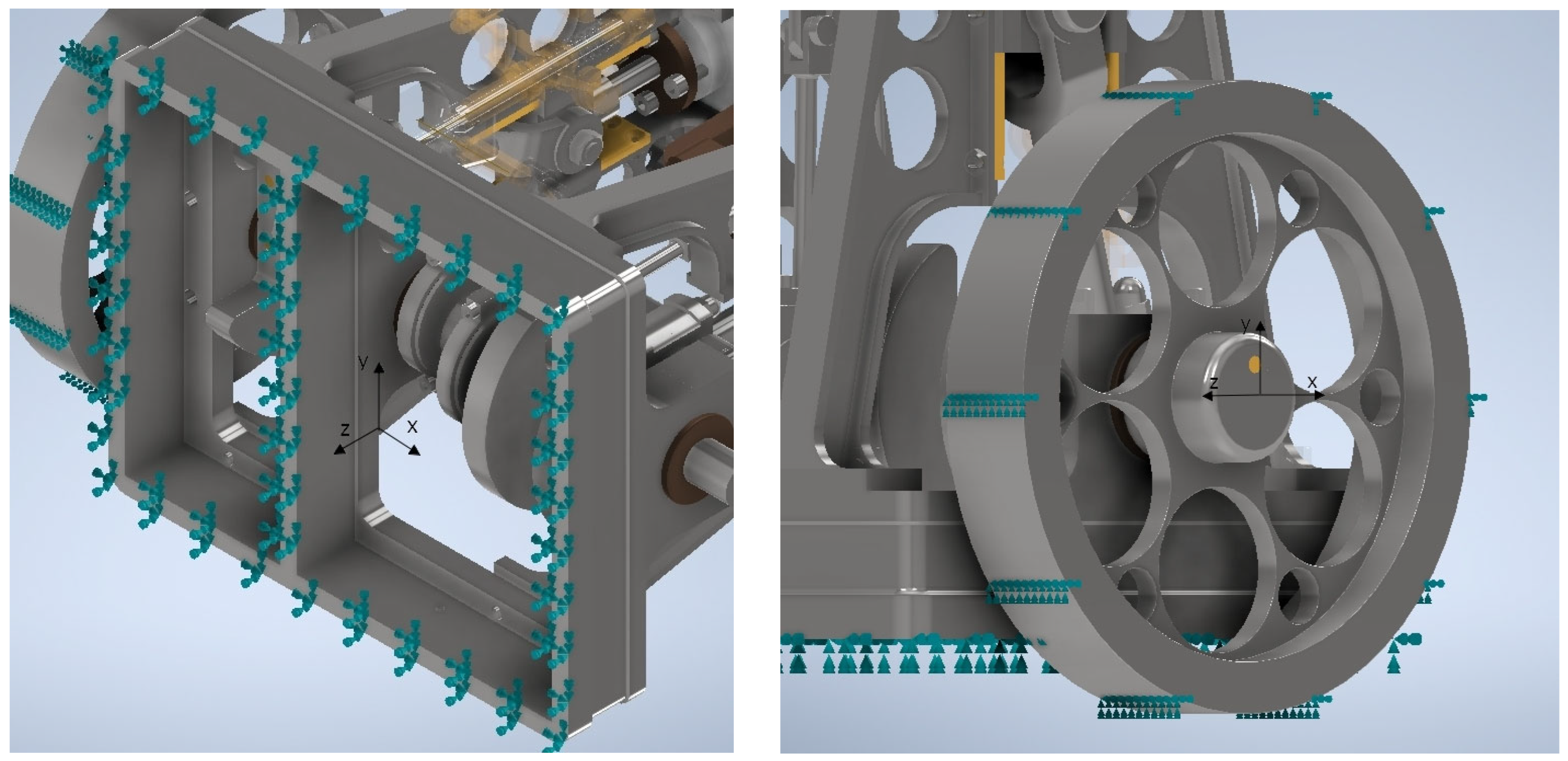
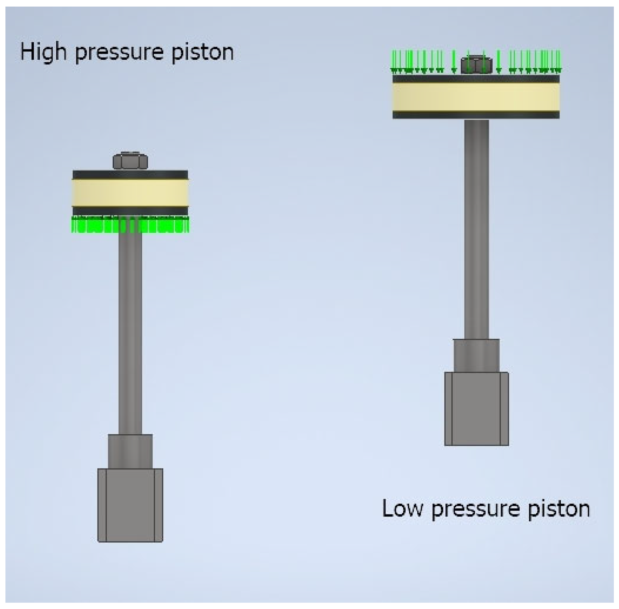
2.2.4. Boundary Conditions
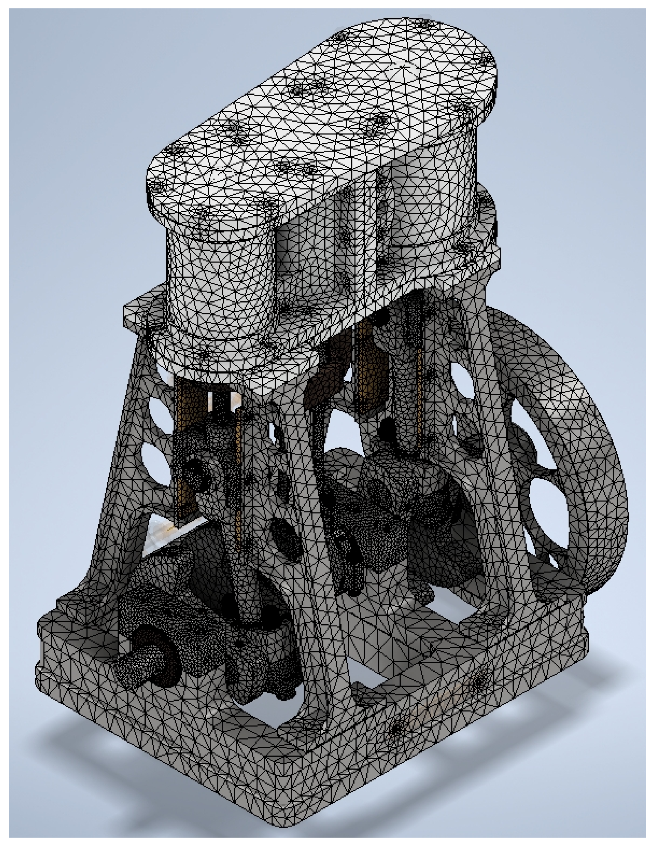
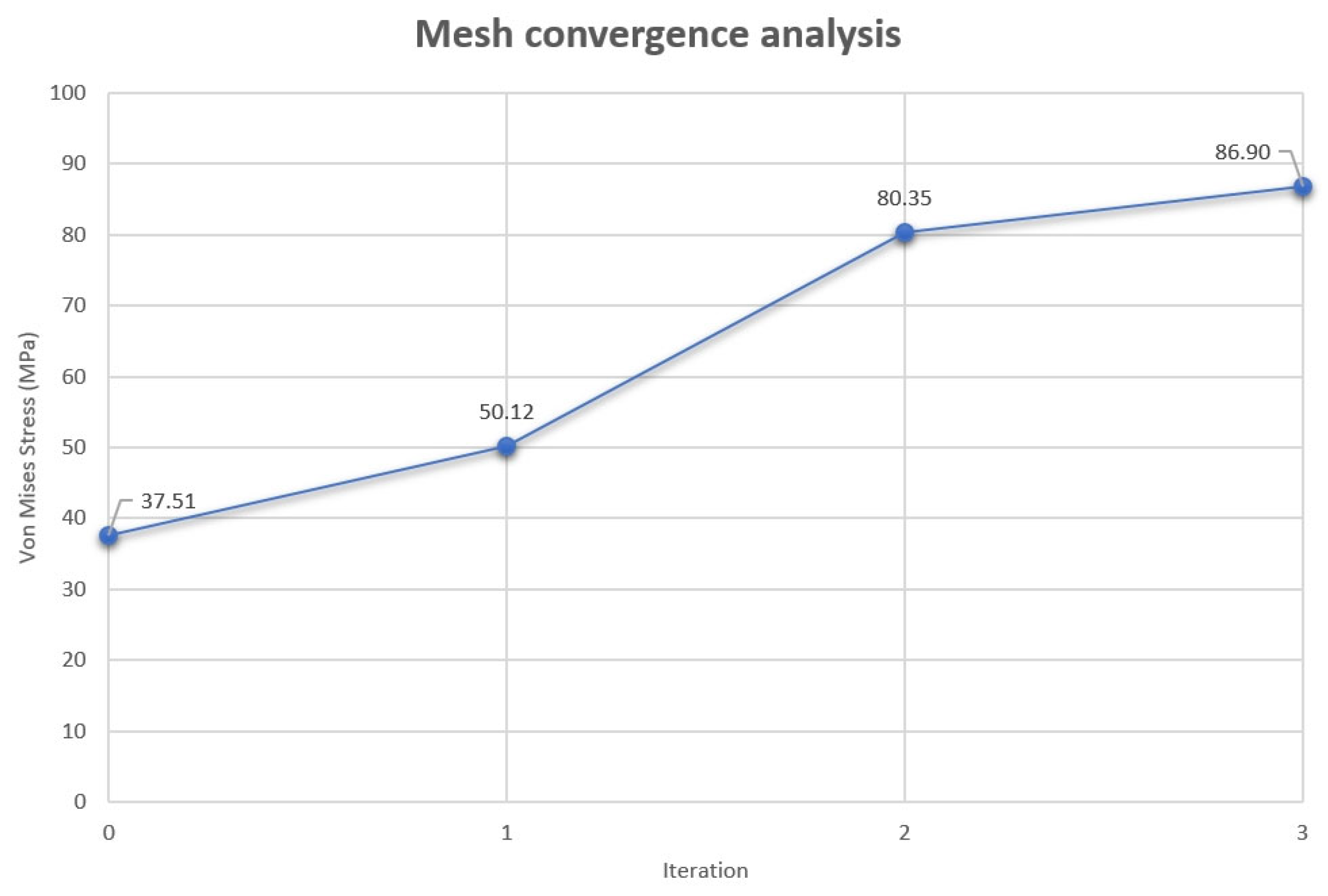
2.2.5. Discretization
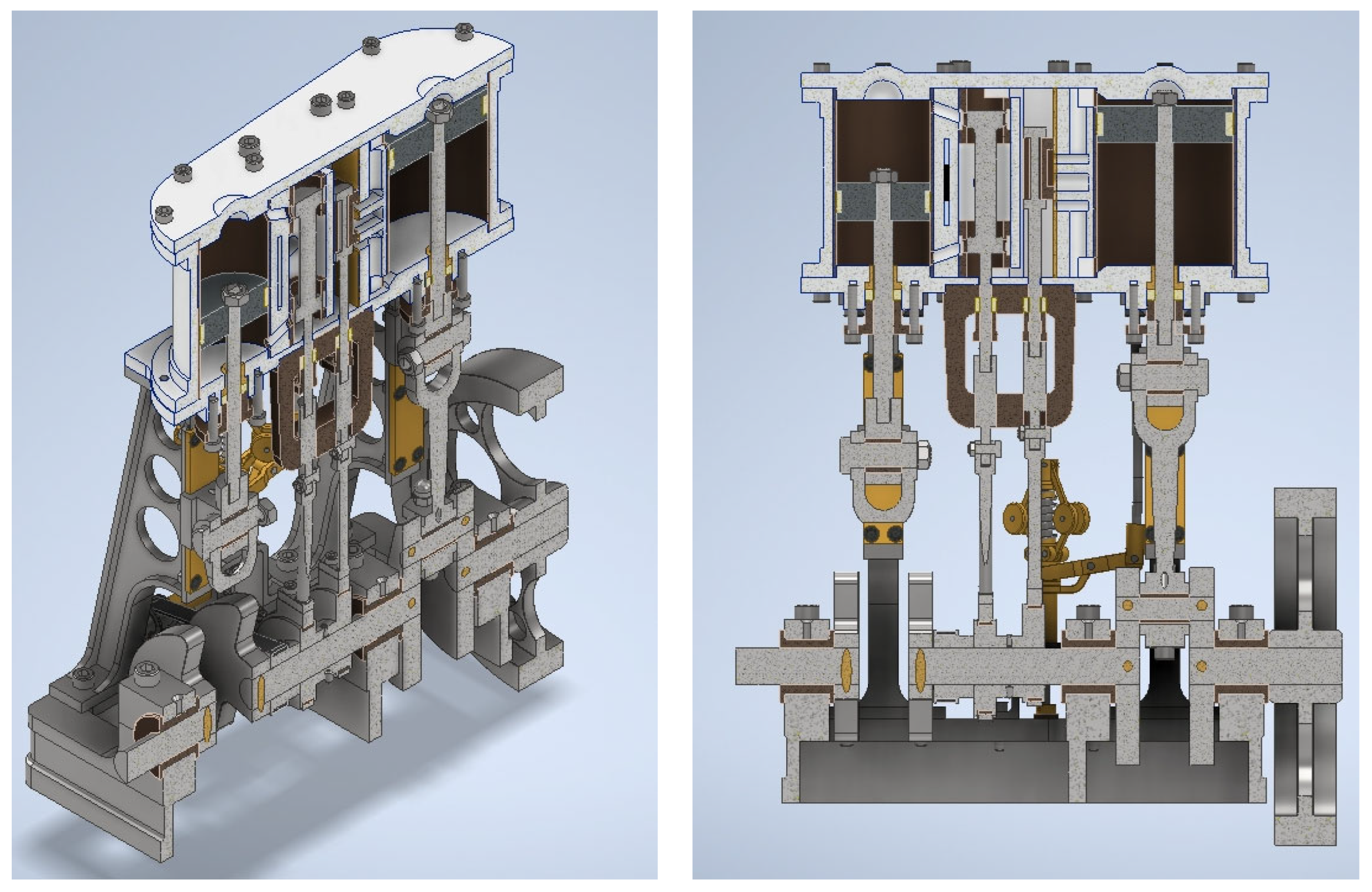
2.2.6. Critical Positions
- Critical position 1: This corresponds to the position of the high-pressure piston plunger in its movement from top dead center to bottom dead center after the intake closes, just when the expansion of the water vapor begins.
- Critical position 2: This corresponds to the position of the high-pressure piston plunger in its displacement from bottom dead center to top dead center after closing the intake, just at the beginning of the expansion of the water vapor.
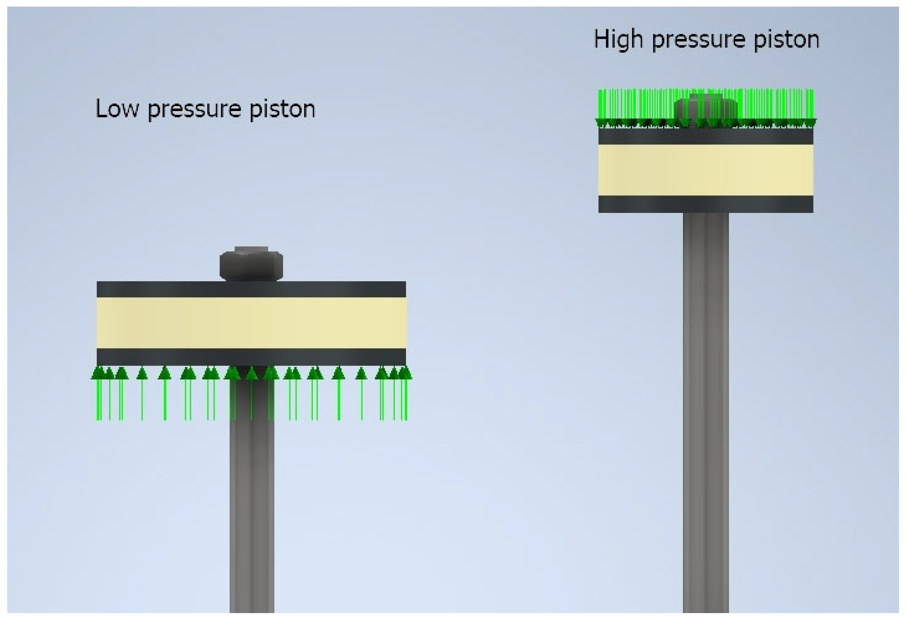
2.2.7. Determination of the Strain Envelope
2.2.8. Analysis Execution
Modal Analysis
Static Linear Analysis
3. Results and Discussion
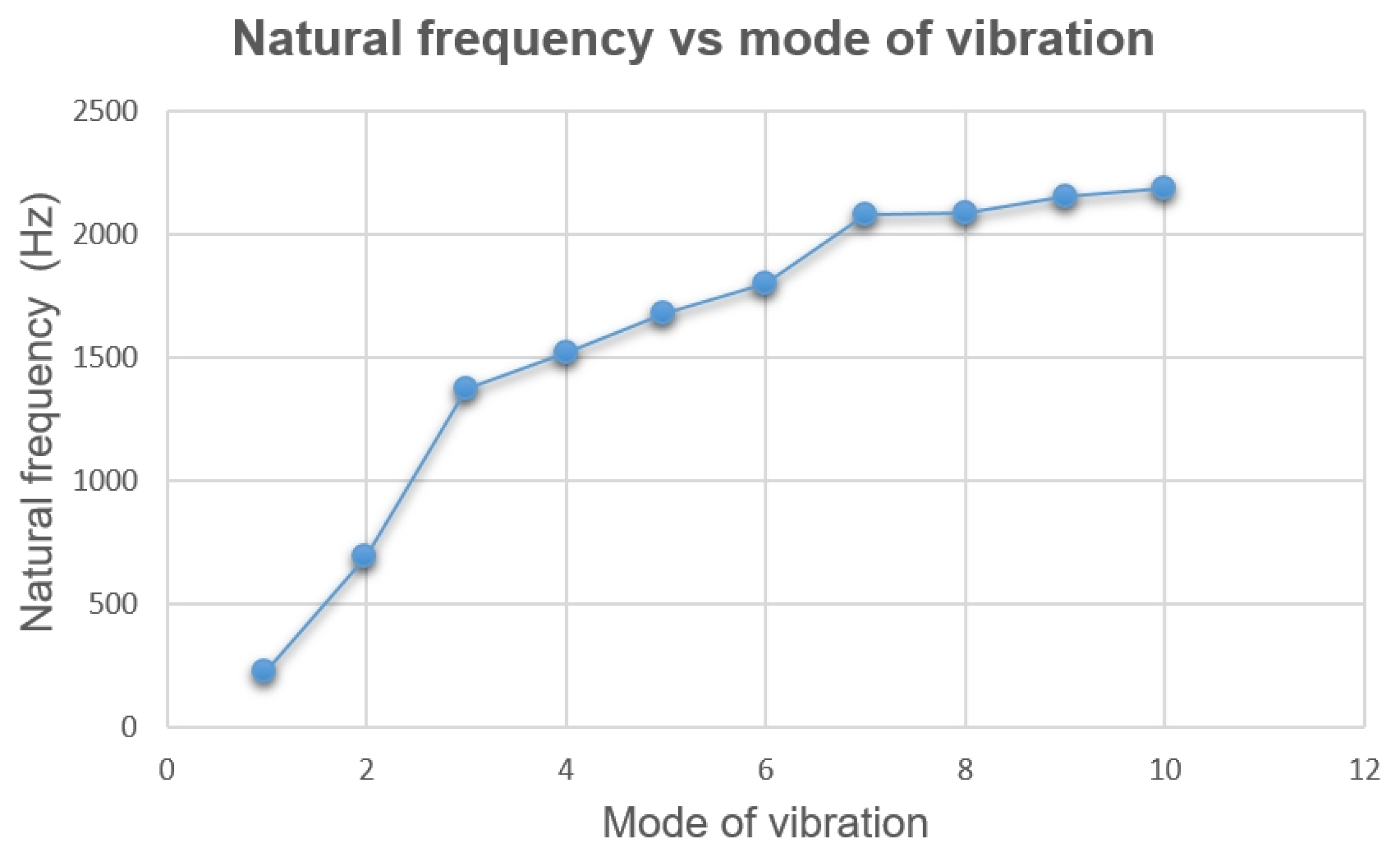
3.1. Modal Analysis
3.1.1. Critical Position 1
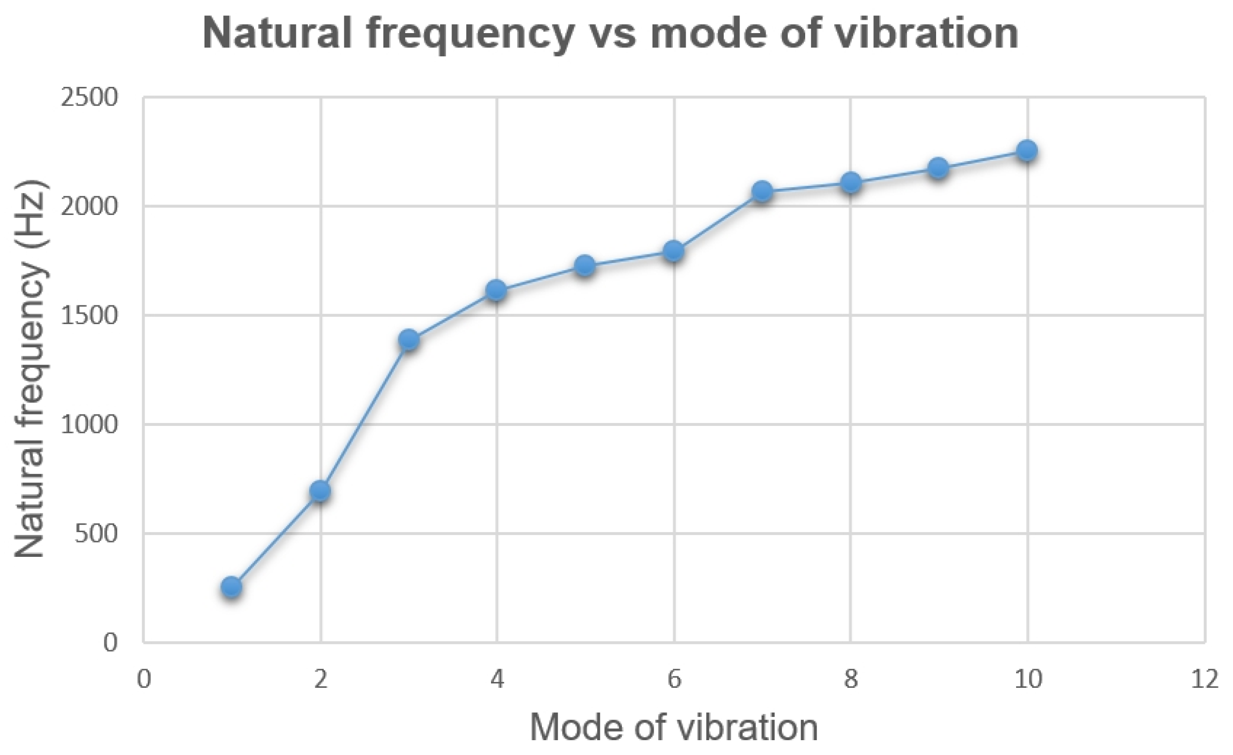
3.1.2. Critical Position 2
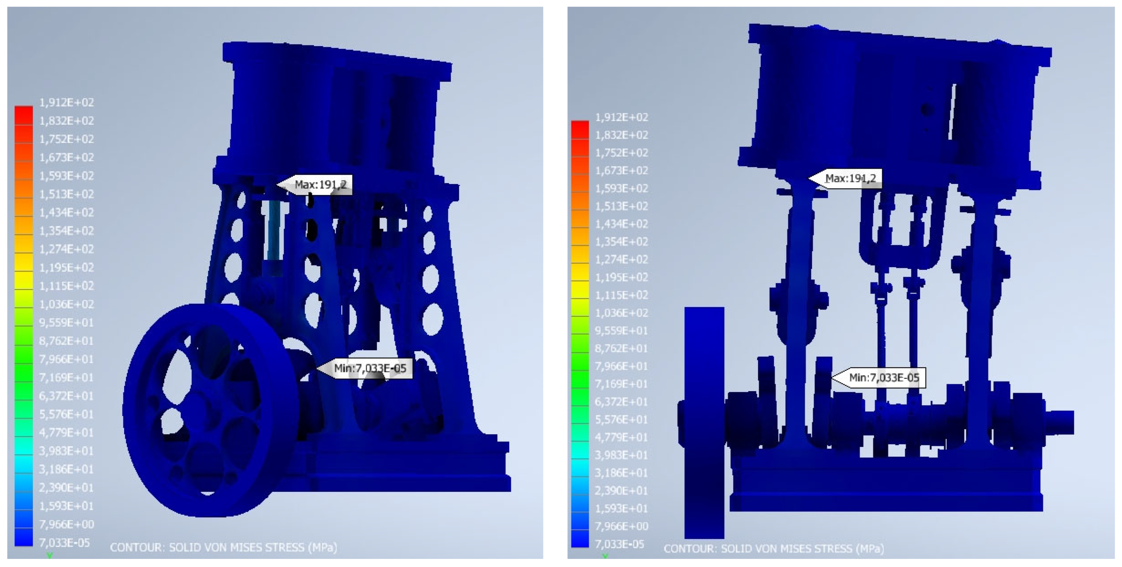
3.2. Static Linear Analysis
3.2.1. Critical Position 1
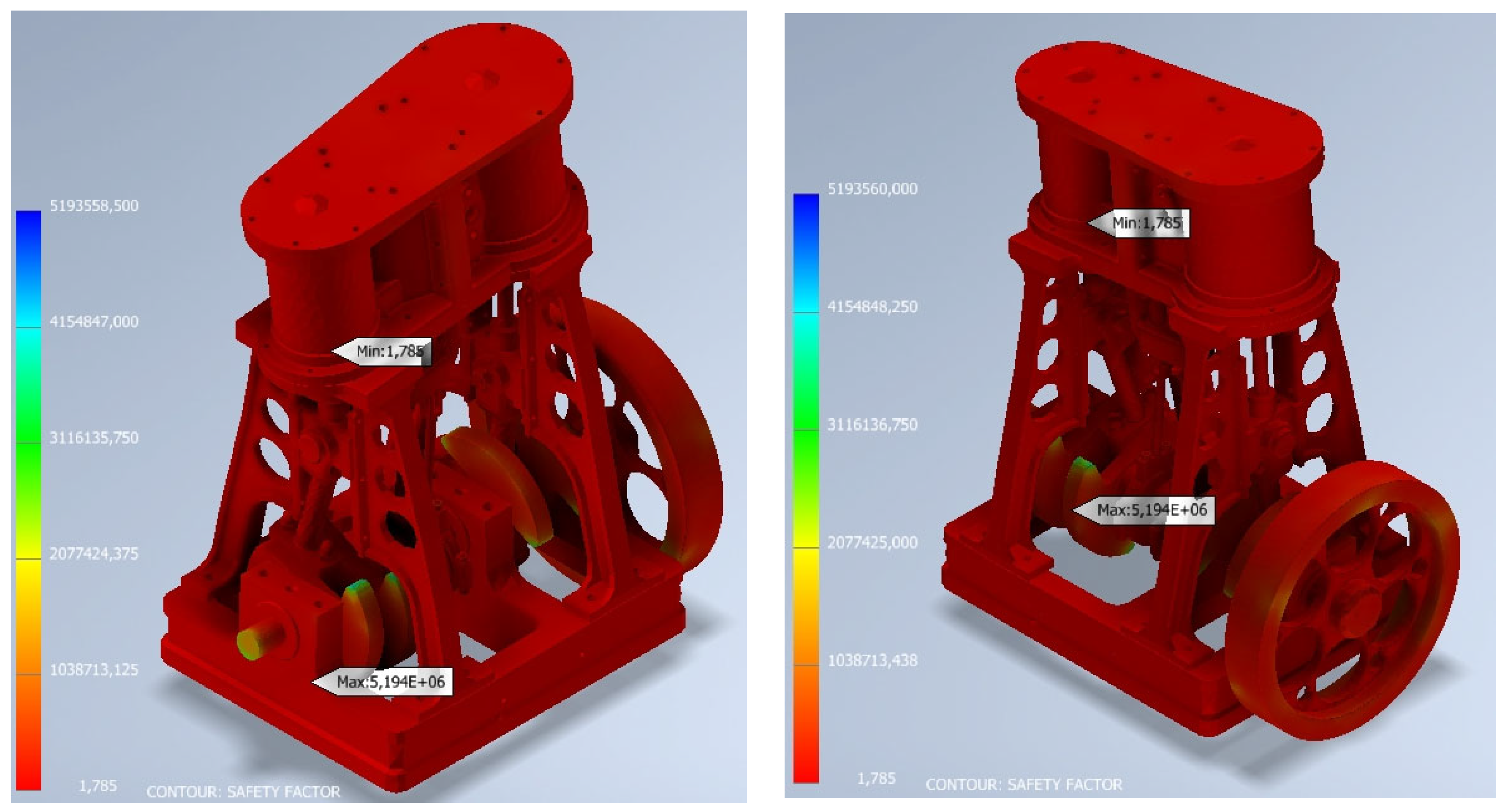
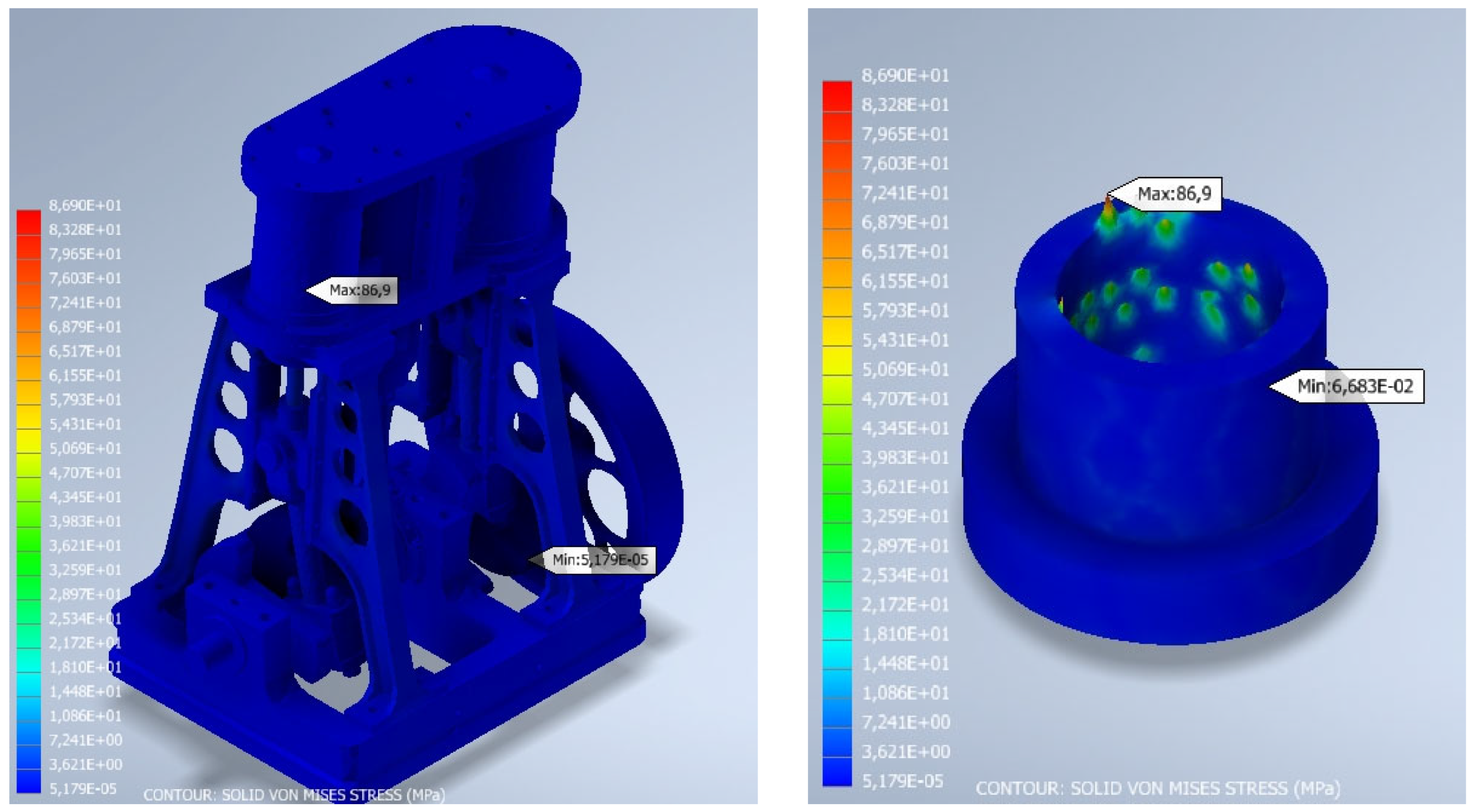
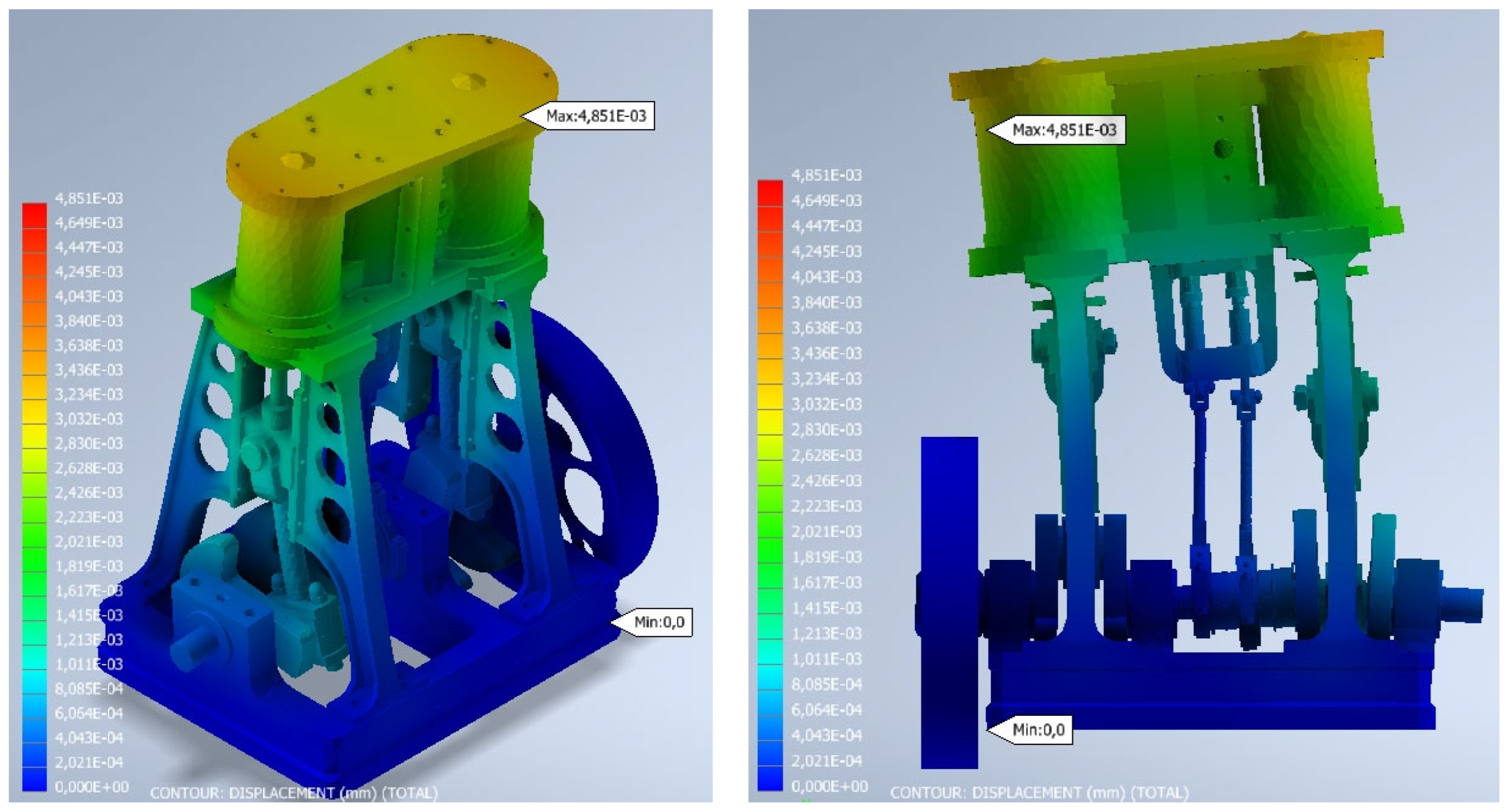
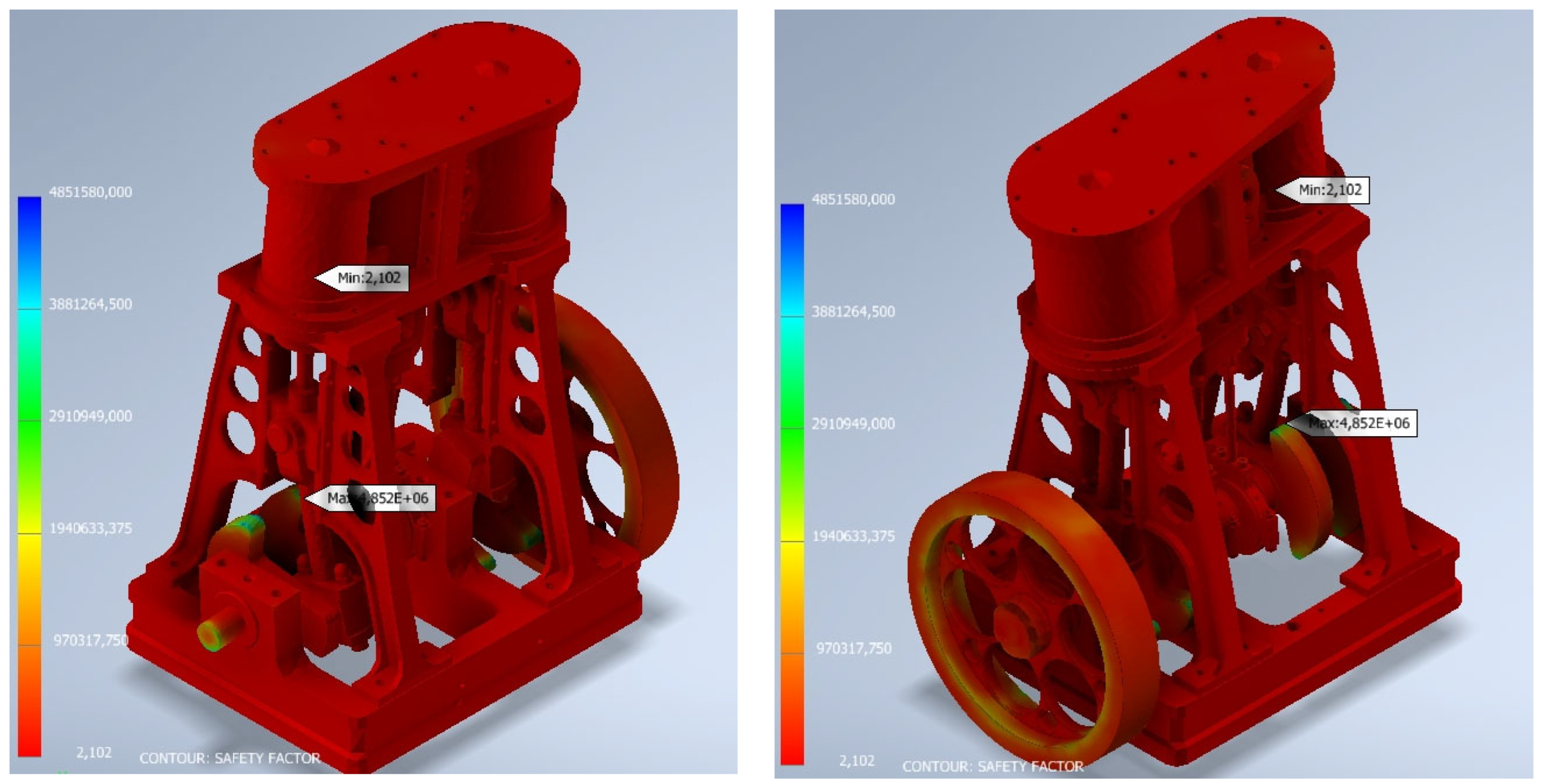
3.2.2. Critical Position 2
3.3. Discussion of the Results
4. Conclusions
Author Contributions
Funding
Institutional Review Board Statement
Informed Consent Statement
Data Availability Statement
Acknowledgments
Conflicts of Interest
References
- Inkster, I. (Ed.) History of Technology; Bloomsbury Academic: London, UK, 2004; Volume 25. [Google Scholar]
- Jenkins, R. Links in the History of Engineering and Technology from Tudor Times; The Newcomen Society at the Cambridge University Press: Cambridge, UK, 1971. [Google Scholar]
- Russell, B. James Watt: Making the World Anew; Reaktion Books: London, UK, 2014. [Google Scholar]
- Rojas-Sola, J.I.; Galán-Moral, B.; De la Morena-de la Fuente, E. Agustín de Betancourt’s double-acting steam engine: Geometric modeling and virtual reconstruction. Symmetry 2018, 10, 351. [Google Scholar] [CrossRef] [Green Version]
- Rojas-Sola, J.I.; De la Morena-de la Fuente, E. Agustín de Betancourt’s double-acting steam engine: Analysis through computer-aided engineering. Appl. Sci. 2018, 8, 2309. [Google Scholar] [CrossRef] [Green Version]
- Who Was Henry Muncaster? Available online: https://modelengineeringwebsite.com/Henry_Muncaster.html (accessed on 13 July 2023).
- Muncaster, H. Model Stationary Engines—Their Design and Construction; TEE Publishing Ltd.: Oxford, UK, 1912. [Google Scholar]
- Rojas-Sola, J.I.; Gutiérrez-Antúnez, J.F. Analysis of the design of the single-cylinder steam engine of the grasshopper beam by Henry Muncaster. Machines 2023, 11, 703. [Google Scholar] [CrossRef]
- Rojas-Sola, J.I.; Gutiérrez-Antúnez, J.F. Geometric modeling and digital restitution of a two-cylinder compound vertical steam engine with speed control by Henry Muncaster. In Advances in Engineering Design IV, 1st ed.; Accepted for Publication; Manchado del Val, C., Suffo Pino, M., Miralbés Buil, R., Moreno Sánchez, D., Moreno Nieto, F.D., Eds.; Springer: Cham, Switzerland, 2024. [Google Scholar]
- Two-Cylinder Compound Vertical Marine Engine. Available online: https://modelengineeringwebsite.com/Muncaster_compound.html (accessed on 13 July 2023).
- Edgar, T. Westbury. Available online: https://en.wikipedia.org/wiki/Edgar_T._Westbury (accessed on 13 July 2023).
- Liu, Y.; Huang, M.; An, Q.; Bai, L.; Shang, D.Y. Dynamic characteristic analysis and structural optimization design of the large mining headrame. Machines 2022, 10, 510. [Google Scholar] [CrossRef]
- Stavroulakis, G.E.; Charalambidi, B.G.; Koutsianitis, P. Review of computational mechanics, optimization, and machine learning tools for digital twins applied to infrastructures. Appl. Sci. 2022, 12, 11997. [Google Scholar] [CrossRef]
- Jumper, L.; Shih, R.H. Parametric Modeling with Autodesk Inventor 2023; SDC Publications: Mission, KS, USA, 2022. [Google Scholar]
- Autodesk Inventor Nastran 2023. About Tutorials. Available online: https://help.autodesk.com/view/NINCAD/2023/ENU/?guid=GUID-DB7160BE-0C72-47B9-B5EF-FC4925B455CE (accessed on 13 July 2023).


| Material | Young’s Modulus (MPa) | Poisson Coefficient | Density (kg/m3) | Yield Strength (MPa) |
|---|---|---|---|---|
| Carbon Steel | 200,000 | 0.290 | 7850 | 350.00 |
| Stainless Steel | 193,000 | 0.300 | 8000 | 250.00 |
| Cast Iron | 120,500 | 0.300 | 7150 | 758.00 |
| Brass | 109,600 | 0.331 | 8470 | 103.40 |
| Cast Bronze | 109,600 | 0.335 | 8870 | 128.00 |
| Nylon | 2930 | 0.350 | 1130 | 82.75 |
| Aluminum 6061 | 68,900 | 0.330 | 2700 | 275.00 |
| Mode of Vibration | Natural Frequency (Hz) |
|---|---|
| 1 | 222.856 |
| 2 | 690.978 |
| 3 | 1371.334 |
| 4 | 1520.094 |
| 5 | 1678.204 |
| 6 | 1799.994 |
| 7 | 2078.845 |
| 8 | 2089.351 |
| 9 | 2155.662 |
| 10 | 2189.124 |
| Mode of Vibration | Natural Frequency (Hz) |
|---|---|
| 1 | 256.206 |
| 2 | 691.678 |
| 3 | 1386.978 |
| 4 | 1614.984 |
| 5 | 1725.334 |
| 6 | 1793.178 |
| 7 | 2064.468 |
| 8 | 2105.807 |
| 9 | 2172.460 |
| 10 | 2256.000 |
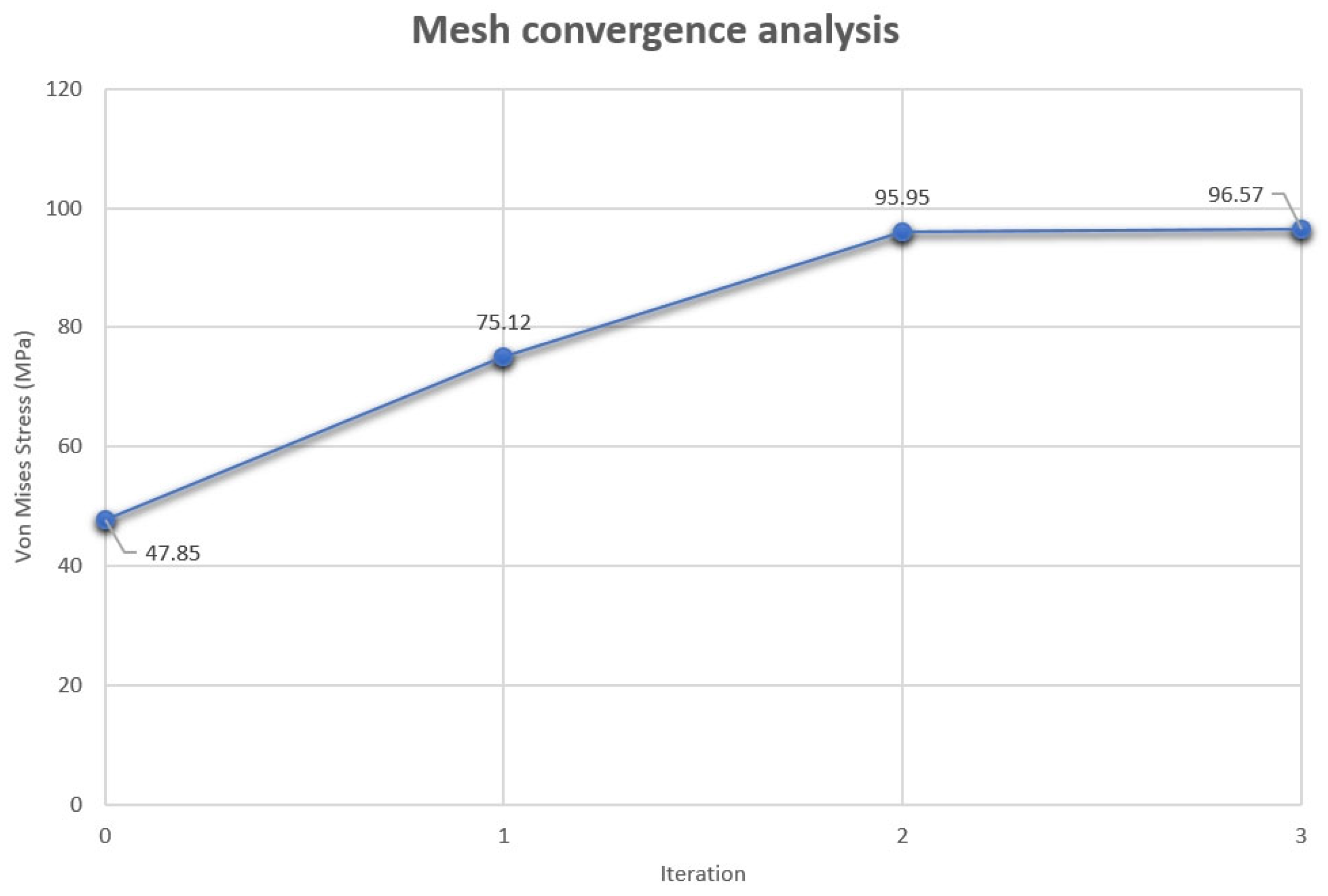
| High-Pressure Piston Rod Cap Element Size (mm) | High-Pressure Piston Rod Cap Element Size (mm) | Iteration | Von Mises Stress (MPa) | Relative Error (%) |
|---|---|---|---|---|
| 0.75 | 2.75 | 0 | 47.85 | - |
| 0.45 | 1.25 | 1 | 75.12 | 36.30 |
| 0.425 | 1.125 | 2 | 95.95 | 21.71 |
| 0.38 | 0.9 | 3 | 96.57 | 0.64 |
| High-Pressure Piston Rod Cap Element Size (mm) | High-Pressure Piston Rod Cap Element Size (mm) | Iteration | Von Mises Stress (MPa) | Relative Error (%) |
|---|---|---|---|---|
| 0.88 | 3.90 | 0 | 37.51 | - |
| 0.60 | 2 | 1 | 50.12 | 25.16 |
| 0.40 | 1.25 | 2 | 80.35 | 37.62 |
| 0.38 | 1.15 | 3 | 86.90 | 7.53 |
| Variable | Value |
|---|---|
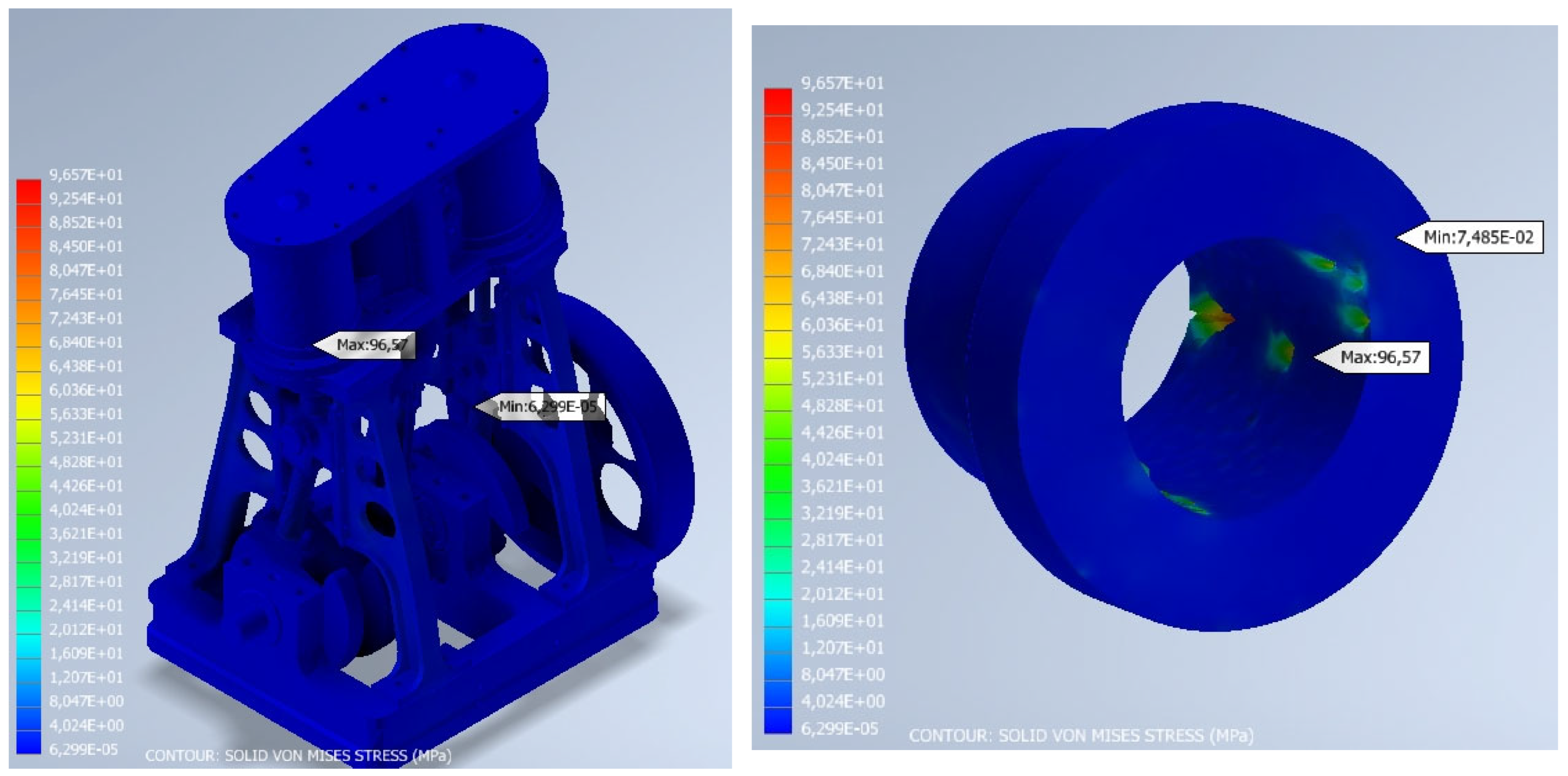
| Von Mises stress (maximum value; MPa) | 96.57 |
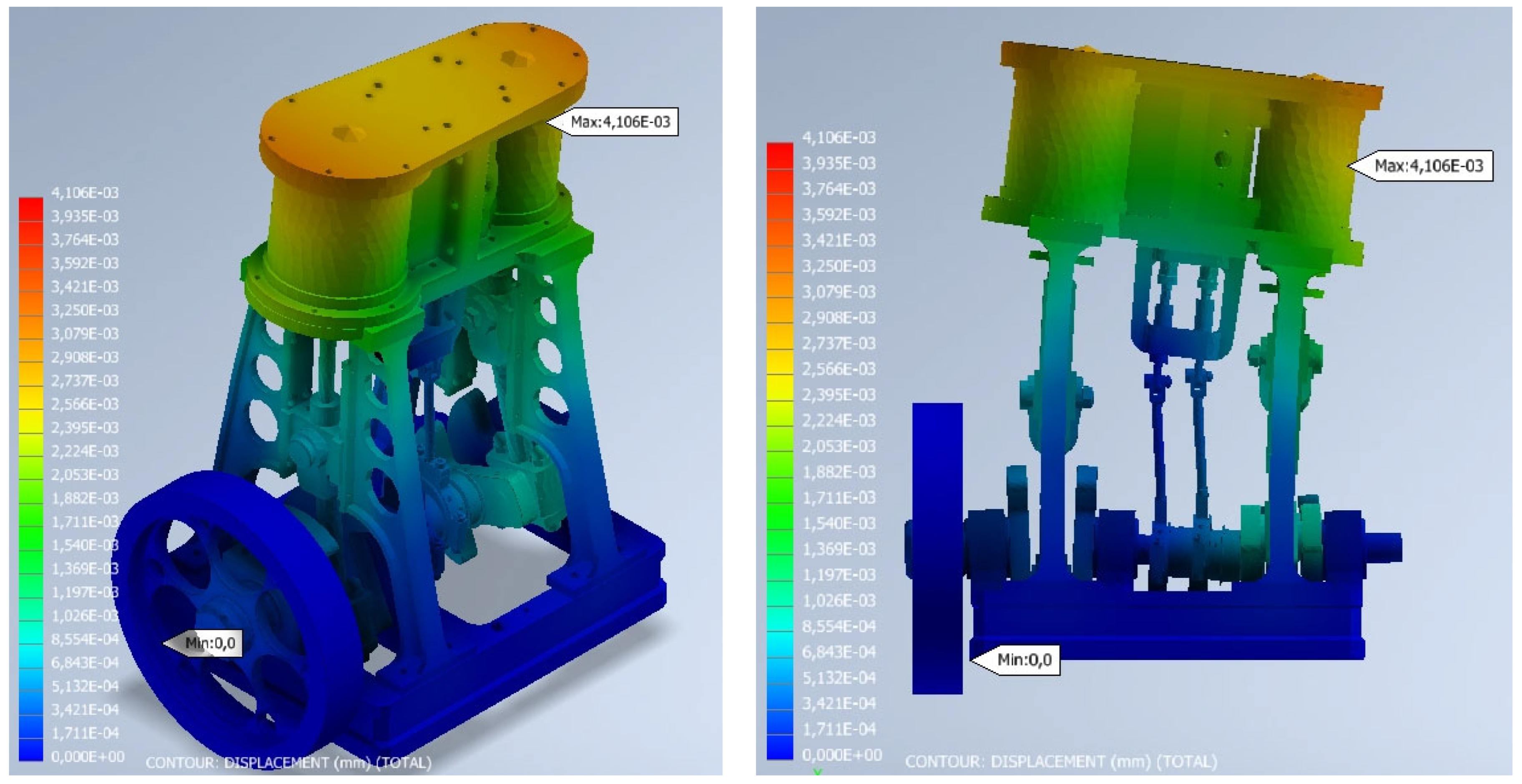
| Displacement (maximum value; mm) | 4.106 × 10⁻³ |
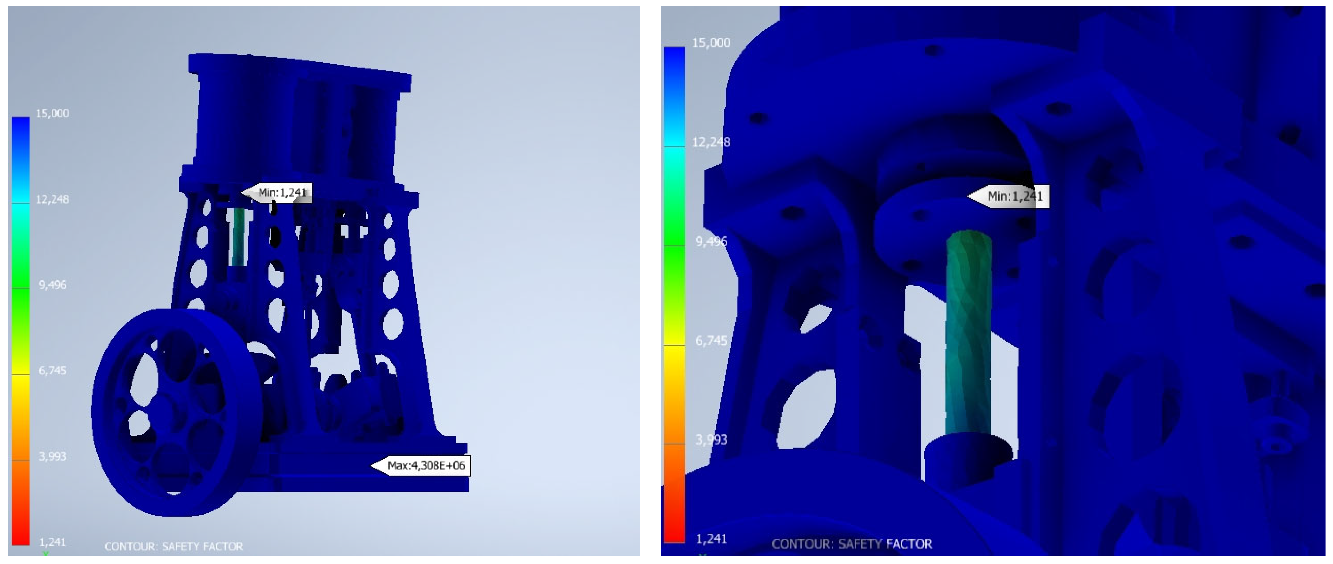
| Safety factor (minimum value) | 1.785 |
| Variable | Value |
|---|---|
| Von Mises stress (maximum value; MPa) | 86.90 |
| Displacement (maximum value; mm) | 4.851 × 10⁻³ |
| Safety factor (minimum value) | 2.102 |
Disclaimer/Publisher’s Note: The statements, opinions and data contained in all publications are solely those of the individual author(s) and contributor(s) and not of MDPI and/or the editor(s). MDPI and/or the editor(s) disclaim responsibility for any injury to people or property resulting from any ideas, methods, instructions or products referred to in the content. |
© 2023 by the authors. Licensee MDPI, Basel, Switzerland. This article is an open access article distributed under the terms and conditions of the Creative Commons Attribution (CC BY) license (https://creativecommons.org/licenses/by/4.0/).
Share and Cite
Rojas-Sola, J.I.; Gutiérrez-Antúnez, J.F. Analysis of the Design of Henry Muncaster’s Two-Cylinder Compound Vertical Steam Engine with Speed Control. Appl. Sci. 2023, 13, 9150. https://doi.org/10.3390/app13169150
Rojas-Sola JI, Gutiérrez-Antúnez JF. Analysis of the Design of Henry Muncaster’s Two-Cylinder Compound Vertical Steam Engine with Speed Control. Applied Sciences. 2023; 13(16):9150. https://doi.org/10.3390/app13169150
Chicago/Turabian StyleRojas-Sola, José Ignacio, and José Francisco Gutiérrez-Antúnez. 2023. "Analysis of the Design of Henry Muncaster’s Two-Cylinder Compound Vertical Steam Engine with Speed Control" Applied Sciences 13, no. 16: 9150. https://doi.org/10.3390/app13169150