
Robust Input Shapers for Acceleration-Limit Actuators


Department of Mechanical Engineering, Chosun University, 309 Pilmun-daero, Dong-gu, Gwangju 61452, Republic of Korea
*
Author to whom correspondence should be addressed.
Appl. Sci. 2023, 13(22), 12499; https://doi.org/10.3390/app132212499
Submission received: 13 October 2023
/
Revised: 10 November 2023
/
Accepted: 14 November 2023
/
Published: 20 November 2023
(This article belongs to the Special Issue Machine Automation: System Design, Analysis and Control)
Abstract
:In this study, robust input shapers consisting of only three impulses are proposed for reducing the residual deflection of flexible systems with acceleration-limit actuators, while maintaining the robust control performance associated with system parameter uncertainties. The unequal acceleration and braking delays of such actuators can produce large residual oscillations owing to the distortion of shaped commands in undamped flexible systems during rest-to-rest operations. Thus, two types of robust input shapers are analytically developed using a phase vector approach with the adoption of the ramp-step function to approximate the dynamics of acceleration-limit actuators and with the utilization of conventional robust shapers. The proposed robust input shapers are numerically evaluated with respect to the command completeness effect, and the residual deflection and parameter uncertainties are experimentally validated using a mini bridge crane. The proposed robust shapers exhibit a higher robustness performance than classical robust input shapers.
1. Introduction
Input shaping technology is used to reduce residual oscillations in various flexible systems, including industrial cranes [1,2] and flexible robot joint systems [3]. Input shapers enhance robustness with added impulses to ensure good control performance. However, conventional input shapers have achieved zero-residual-deflection control performance with accurate system modeling and ideal actuators, whereas acceleration-limit actuators are commonly employed owing to their cost-effective industrial applications. Therefore, new robust input shapers must be developed for practical industrial applications of input shaping techniques to flexible systems for maintaining control robustness under acceleration-limit actuators.
Input shaping is implemented via the convolving of an input command with an impulse sequence comprising magnitudes and time locations determined by solving a set of constraint equations to generate a shaped input [4,5,6]. The constraint on the percentage residual oscillation amplitude (PRA) can be expressed as the ratio of the residual oscillation amplitudes with and without shaping. For an undamped model of a second-order linear system, is expressed as:
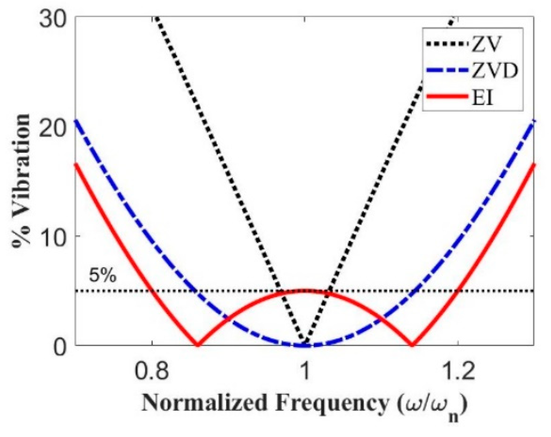
where , , and represent the natural frequency of the system, and the magnitude and time location of the th impulse, respectively. By setting regarding the actuator performance limit and the shortest duration, a zero vibration (ZV) shaper [7] was obtained with the least amount of robustness because the residual oscillation increases rapidly as the modeling parameter is deviated. To improve the robustness of input shapers against system modeling errors, a ZV and derivative (ZVD) shaper [8] was developed using the derivative with respect to the frequency of = 0 as an additional constraint. To further improve the robustness by allowing a tolerable level of residual oscillation, an extra-insensitive (EI) shaper [9] was proposed. For the qualitative measurement of the robustness of input shapers, a sensitivity curve is displayed in Figure 1, indicating the change in residual oscillation as a function of the modeling error. Insensitivity is a measurement of the relative robustness of shapers and is defined as the width of the sensitivity curve at a tolerable percentage oscillation level with respect to the parameter of interest. Even if the EI and ZVD shapers produce longer insensitivity than the ZV shaper at , these input shapers are developed under the assumption of linear system theory which means that their robustness performance is questionable for nonlinear dynamics.
Considering the nonlinear dynamics of actuators, several input shapers have been proposed for ramp [10,11], first-order [12,13], and asymmetric 2nd-order [14] actuators. However, nonlinear dynamics can be attributed to discontinuous nonlinearities within a system, such as backlash, saturation, rate-limiting, and dead-zone. When a hard nonlinearity distorts an input-shaped command, the oscillation reduction performance of the input shapers can be significantly degraded [15,16]. The effects of backlash [17] and Coulomb friction [18] on an input-shaping control system were considered and techniques for the input shaper redesign to reduce the detrimental effects of nonlinearities were presented. However, all previous studies have focused on developing input shaping techniques against the nonlinearities of actuators rather than improving control robustness while addressing nonlinear dynamics.
As an alternative approach to improve the control robustness of input shapers, nonlinear optimization is required with the typical constraints of transient oscillation [19], robustness [20], and time optimality [21,22]. Although these approaches are powerful, they require high computational power and reliable algorithms; therefore, they are impractical in real-time applications. In addition, more impulse sequences for these input shapers should be employed to maintain robust control performance against system modeling errors. Because the input-shaping technology is a time-delayed filter, it is desirable to include as short a sequence as possible while maximizing the robustness performance for practical and cost-effective industrial implementations under non-ideal effects.
The primary contribution of this study is the development of two analytically robust input shapers with only three impulse sequences under acceleration-limit actuators using a vector diagram approach [15,23]. First, a pendulum system is utilized for the phasor-vector formulation to express the steady-state response. A ramp-step function is employed to approximate the response of the acceleration-limit actuator. Second, two types of robust input shapers are strategically developed with the utilization of the analytical impulse magnitudes of classical robust input shapers. Third, the proposed robust input shapers are numerically evaluated with respect to the duration, actuator parameters, and flexible system parameters. Finally, the sensitivity and residual deflections of the proposed robust input shapers are experimentally validated using a mini bridge crane.
2. Robust Input Shapers for Acceleration-Limit Actuators
In this section, two types of robust input shapers were analytically developed with only three impulse sequences for the oscillation reduction of flexible system operations with acceleration-limit actuators during point-to-point maneuvers. In the derivation process, the impulse magnitudes of the linear robust input shapers that satisfied the actuator performance limit were utilized to determine the impulse time locations. Two types of robust input shapers are presented besides a phasor vector representation of a ramp function to approximate the distorted input command profile, as described below.
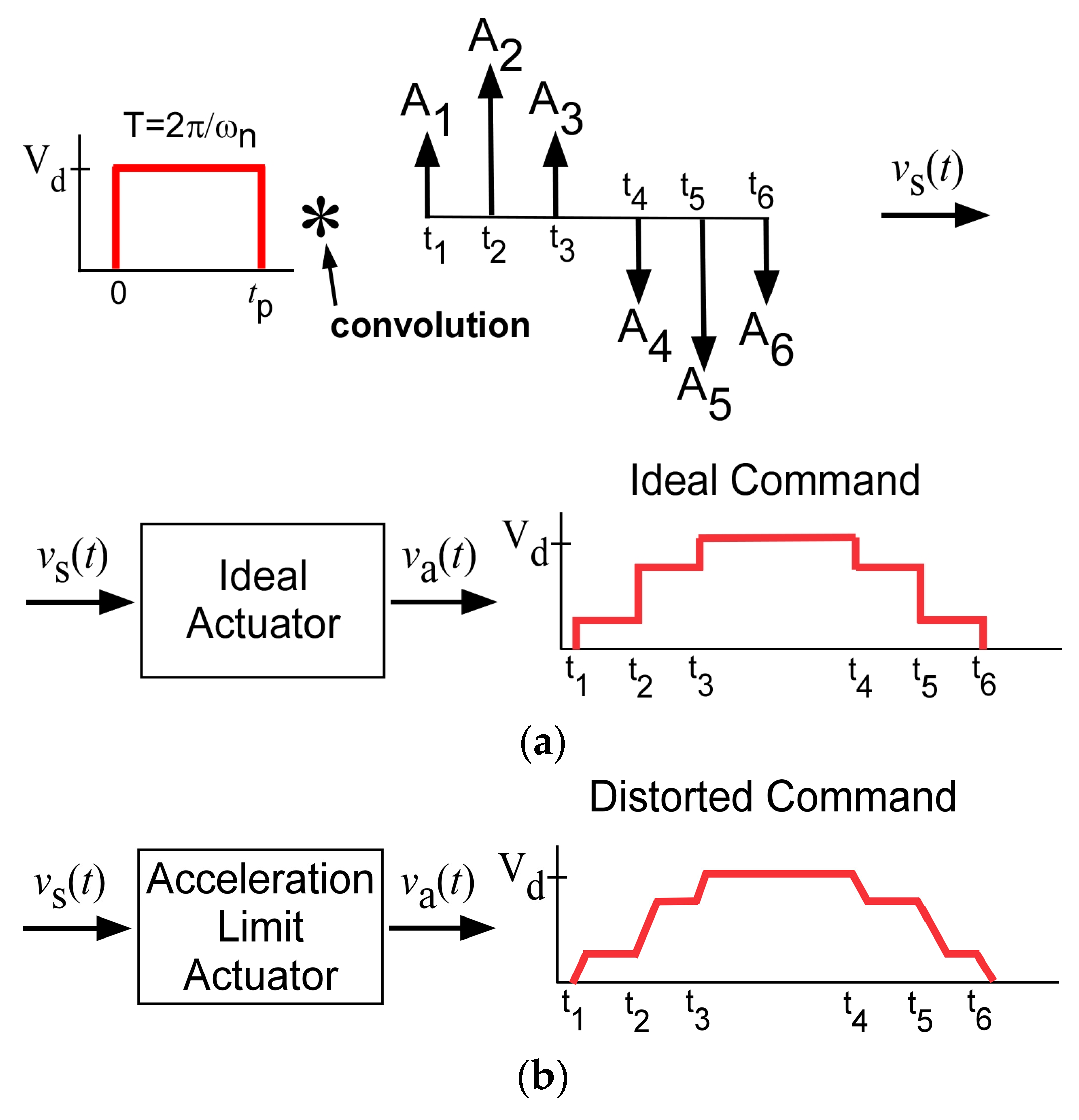
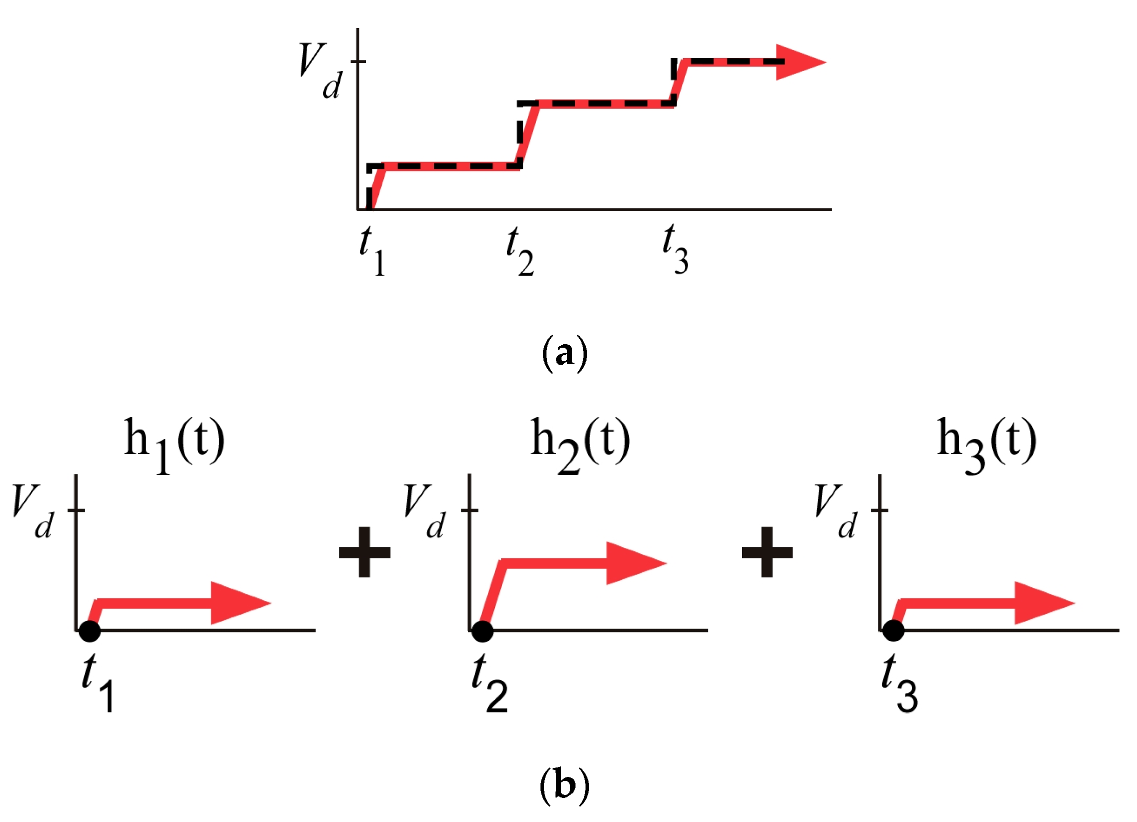
In the case of ideal actuators with infinite acceleration and braking performances, ideal-shaped input commands were generated by convolving the pulse input and three impulse sequences, where and are the amplitude and time location of the impulse, respectively, as shown in Figure 2a. An acceleration-limit actuator that generates ramp-shaped input commands changes its own input commands, as shown in Figure 2b. These distorted input commands degrade the control performance of flexible systems and produce large residual oscillations.
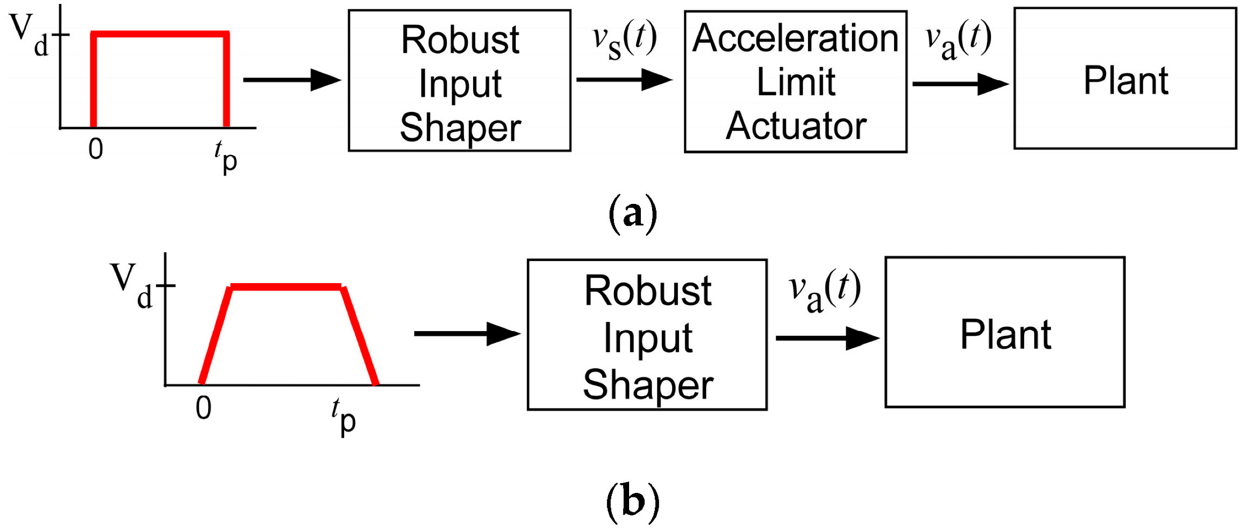
In Figure 2, represents the desired velocity of the actuator and represents the velocity shaped by the input shaper. To develop an input shaper for such a nonlinear input command profile, the input command is transformed and simplified into a ramp shape, as depicted in Figure 3. This approach, with an equivalent constraint, provides a solution process that can be reformulated to develop an input shaper for the distorted command [11].
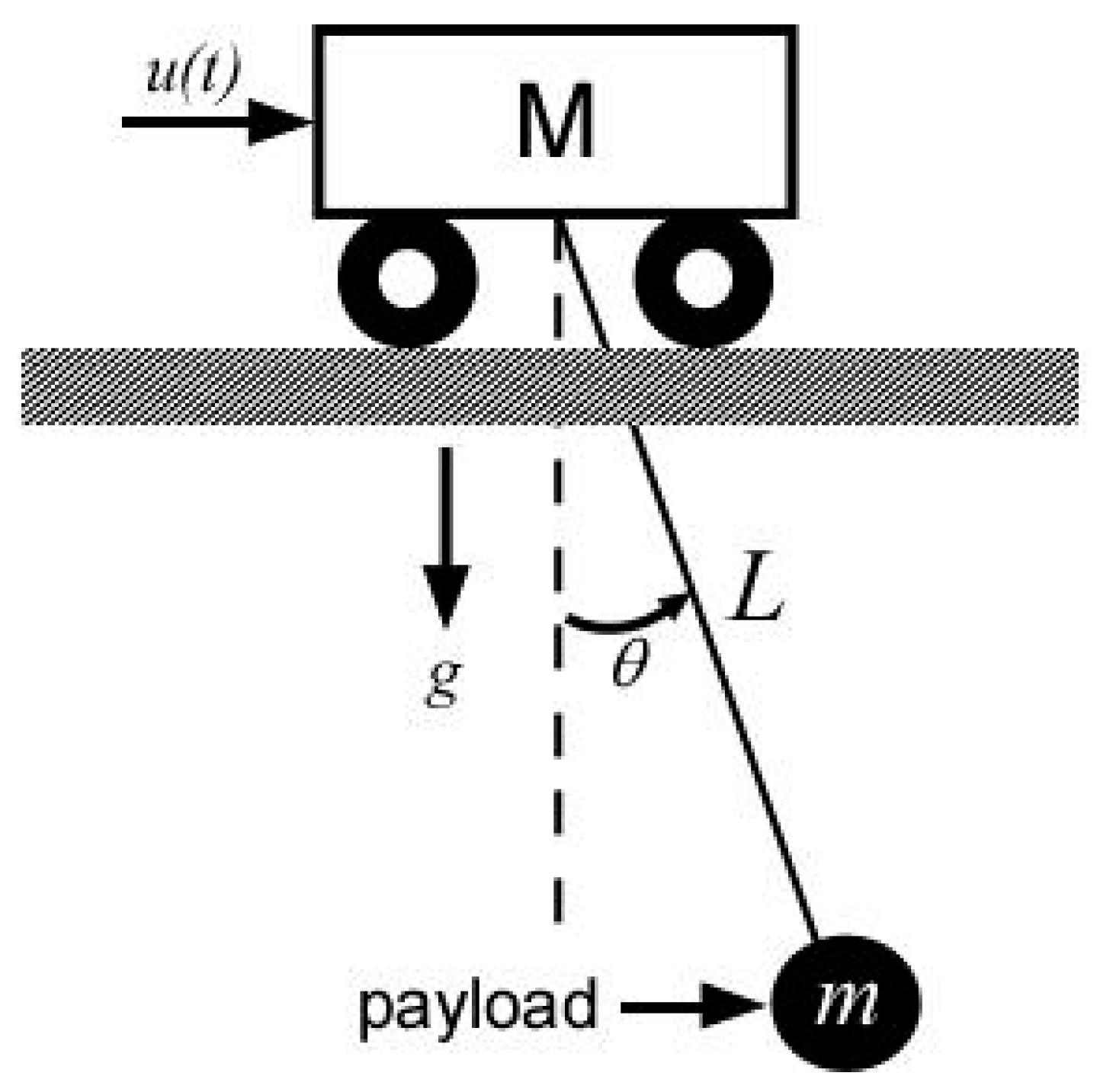
To present the two types of robust input shapers using the modified process described above, a single-pendulum system was utilized with ramp-type input commands, as shown in Figure 4. The equation of motion is given as:
where represents the velocity input command, L represents the system string length from the trolley to the payload, and g represents the gravitational acceleration. Assuming that is sufficiently small, Equation (2) is Laplace transformed as:
where represents the Laplace transform of . The output of the system is reformulated as the system input and the sine input to be expressed in phasor form as:
As a key point in the input shaping technique, the steady-state equation can be expressed according to Equation (4) as:
For no residual oscillation, in Equation (5) must be zero. Therefore, can be determined by dividing a command by the impulse time of the input shaper, as presented in Figure 5b, in an acceleration-limit input command in rising mode, as shown in Figure 5a.
As shown in Figure 5, the acceleration limit of the actuator must be considered. The equivalent shaper formulation under the acceleration rate limit can be used with the following restrictions:
Here, and represent the acceleration and deceleration constants, respectively. This condition is enforced to obtain the acceptable control performance of the proposed input shapers without collapsing the command profile. As an analytical approach by utilizing a phaser-vector form of the response function of the pendulum system, a ramp-shaped input command is expressed as:
where represents the function of each region, as displayed in Figure 5. The following equation is obtained via approximation of the nonuniform acceleration and deceleration of the actuator with a ramp-shaped function:
where represents the velocity slope, which is determined according to the acceleration or deceleration, and represents the desired velocity, which can become the maximum velocity of the actuator. Taking the Laplace transform of Equation (8) for each region for vector matching yields:
Using the steady-state response equation in Equation (5), and the magnitude and phase angle of the ramp-shaped input command vector, the command vector of each segment in Figure 5 can be represented as
To equate Equation (5) to zero, the vectors in Equation (11), can be scaled, rotated, or reflected across the real axis without affecting the results. For the vectors to sum to zero, they must form a closed triangle. In addition, the amplitudes of conventional robust input shapers were considered to satisfy the actuator performance limit.
2.1. ZVDAL Input Shaper for Ramp Actuators
This subsection proposes a robust input shaper called the ZVDAL shaper for a wide range of modeling errors in flexible systems with a ramp-shaped velocity profile owing to an acceleration-limit actuator. A robust input shaper is presented utilizing a conventional robust shaper (ZVD shaper) to satisfy the actuator performance constraint and obtain an exact solution without a parameter optimization formulation. The ZVD shaper [8] for linear damped systems is expressed as:
where T represents the period and is the damping ratio of a system oscillation with K = . In the development of , the damping ratio is assumed as . The vector equations in Equation (11) can be expressed assuming that the impulse magnitudes ( = 0.25, = 0.5, and = 0.25) of the shaper are
Normalizing the command vectors in Equations (13)–(15), the phasor vectors can be expressed as:
where
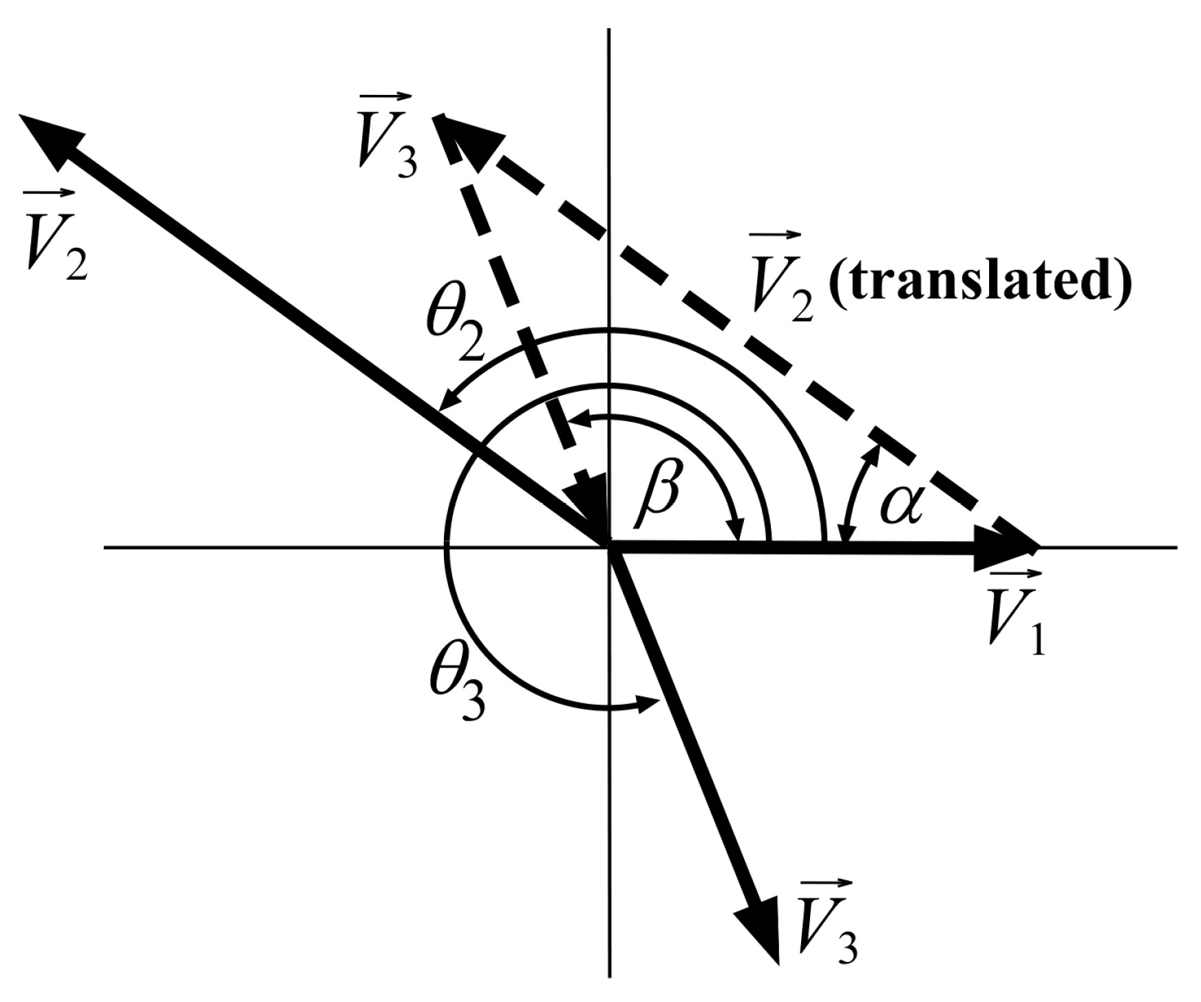
The normalized phase vector equations above can be employed to control the residual deflection using a vector diagram. Each vector of the ZVDAL shaper for the ramp actuator is displayed in Figure 6. The magnitude of the residual deflection is determined by the sum of the three vectors. The angle between and (dotted line) is denoted as and the angle between and (dotted line) is denoted as , as in Figure 6. and are determined using the cosine law as:
The phase angles obtained using the vector geometry in Figure 6 and Equations (17) and (18) can be represented as and . The impulse time locations of the ZVDAL shaper are then determined as
The impulse time must be a real number and the inverse cosine function must include a positive value because must exist after . Each switch time for the stop operation was calculated using the same procedure as that for the start operation. The sign of the impulse magnitude changes asymmetrically, and acceleration and deceleration are considered accordingly. and for the stop operation are expressed as:
where = denotes the pulse duration of the initial input command. The constraint of Equation (26) must be satisfied to verify the effect of the residual deflection performance of the ZVDAL shaper when a ramp-shaped input is assumed to be:
When Equation (26) is satisfied, the ZVDAL shaper reduces the residual deflection in a flexible system with a ramp actuator. Using Equations (22)–(25), the ZVDAL shaper for the stop and start commands of the flexible system can be expressed as:
Equation (27) is used to generate a ramp-shaped command using an actuator with asymmetric acceleration and braking through convolution on a robust input command. The analytical development procedure for the ZVDAL shaper could be expanded to generate various input-shaped commands for acceleration-limit actuators.
2.2. EIAL Input Shaper for Ramp Actuators
In this subsection, a robust input shaper called the EIAL shaper is proposed for reducing a wide range of modeling errors by allowing a certain level ratio (%) of the residual oscillation magnitude under ramp actuators. As in the previous derivation, a robust input shaper was developed by employing a classical EI shaper for the actuator performance constraint and an exact solution for practical implementation. The solution to the EI shaper [9] is expressed as:
where represents the percentage ratio (%) of the allowed residual deflection magnitude in an unshaped case and T represents the period of the flexible systems. Assuming that the impulse magnitudes (, , and ) are given for the EIAL shaper, the vector equations from Equation (11) can be obtained as
Normalizing the command vectors yields the following phasor vectors:
where
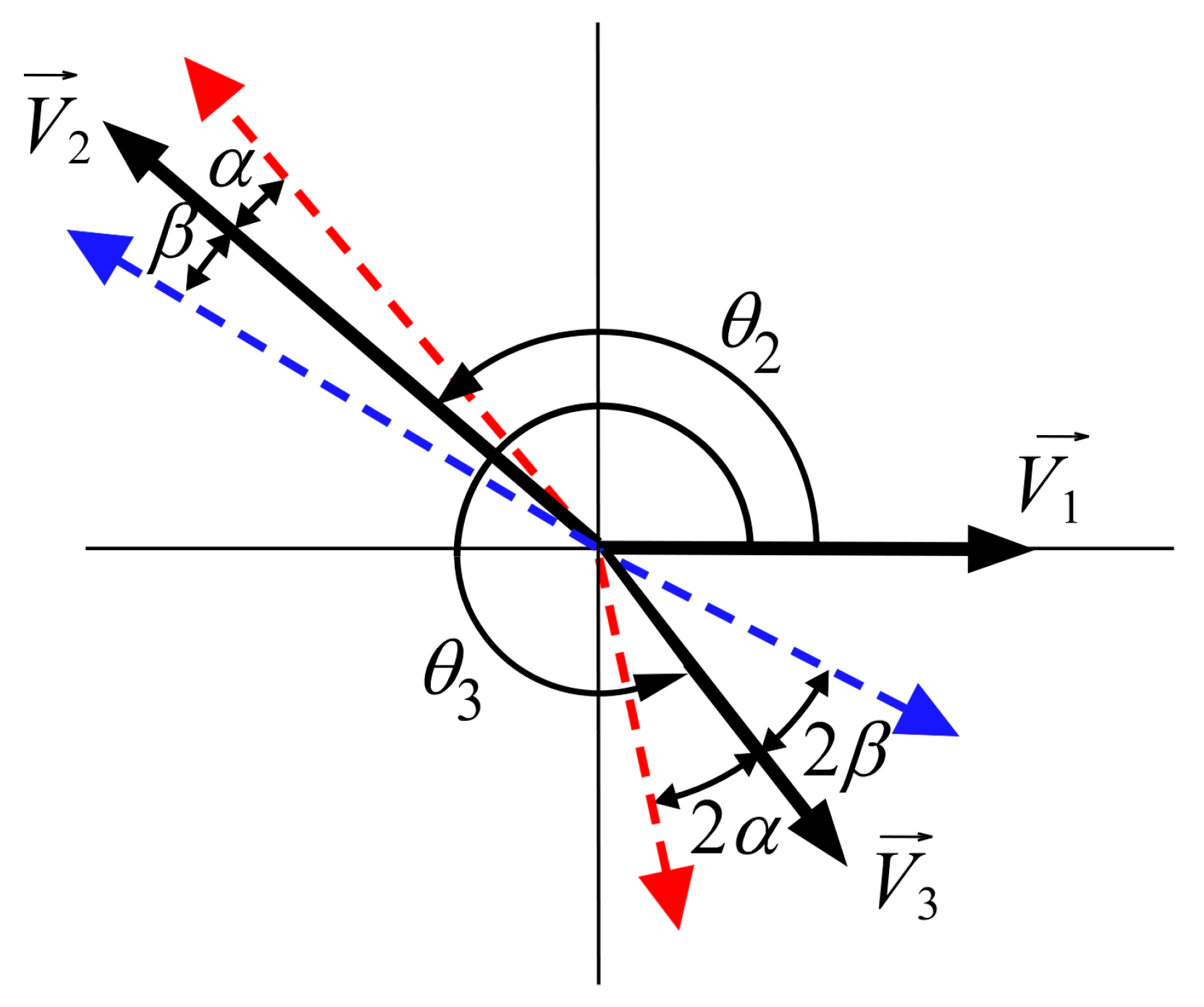
The normalized phasor-vector equations are depicted as vector diagrams in Figure 7. From the sensitivity curve of the shaper shown in Figure 1, the geometric constraints can be set to derive the shaper. The resultant of the 3 vectors, indicated by the black solid arrows at / = 1, must have an allowable deflection magnitude ratio, . For the symmetricity of the sensitivity curve about the modeling frequency, is always constrained [9]. In forcing the sensitivity curve on either side of /=1 to achieve zero residual oscillation, the vector resultant must be zero regarding either or , where and are uncertain angle deviations from / = 1. With the cosine law and the trigonometric identity, the resultant constraints in / 1 are expressed as:
The resultant constraints in / 1 are similar to the above equations except for the deviation. Then, the amplitude condition is obtained as
By setting the resultant magnitude equal to the oscillation limit, at / = 1, the resultant constraint with Equation (38), and , can be expressed as:
where represents the magnitude of unshaped vibrations. Using at /=1, is obtained. From Equations (32)–(35) and (39), the time locations of the EIAL shaper are expressed as:
The switch time for stop operations was the same as that for start operations. The sign of the impulse magnitude changed asymmetrically. In stop operations, deceleration () is used instead of acceleration () in start operations, and the impulse times and for the stop operation are given by:
where represents the pulse duration at the start of the operation. The EIAL shaper must be used under the constraint of Equation (26) owing to the slope of the ramp-shaped velocity profile, similar to the ZVDAL shaper presented in the previous subsection. Under the condition of a ramped velocity profile, the EIAL shaper reduced the residual deflection in a flexible system with a ramp actuator. Using Equations (40)–(43), the EIAL shaper for the start and stop operations of the flexible system can be expressed as
Equation (44) is used to generate a ramp-shaped command using an actuator with asymmetric acceleration and braking through convolution on a robust input command. The analytical development procedure for the EIAL shaper can be expanded to generate commands for various shapes using acceleration-limit actuators.
3. Performance Evaluation
The residual deflection reduction performances of the proposed ZVDAL and EIAL shapers were compared with those of the conventional ZVD and EI shapers. The functionality of the ZVDAL and EIAL shaped commands was affected by changes in duration (), cable length (), acceleration limit (), and deceleration limit (). A pendulum system (Figure 4) was used for performance assessment with the bang-pause-bang input command for point-to-point maneuvers. A numerical analysis was conducted using MATLAB® and the parameters used for robustness evaluation are summarized in Table 1.
3.1. ZVDAL Performance Evaluation
The residual-deflection reduction performance of ZVDAL and conventional ZVD shapers was compared. The control performance of the residual deflection reduction was evaluated with respect to the completeness of the commands and robustness with a wide range of modeling parameters.
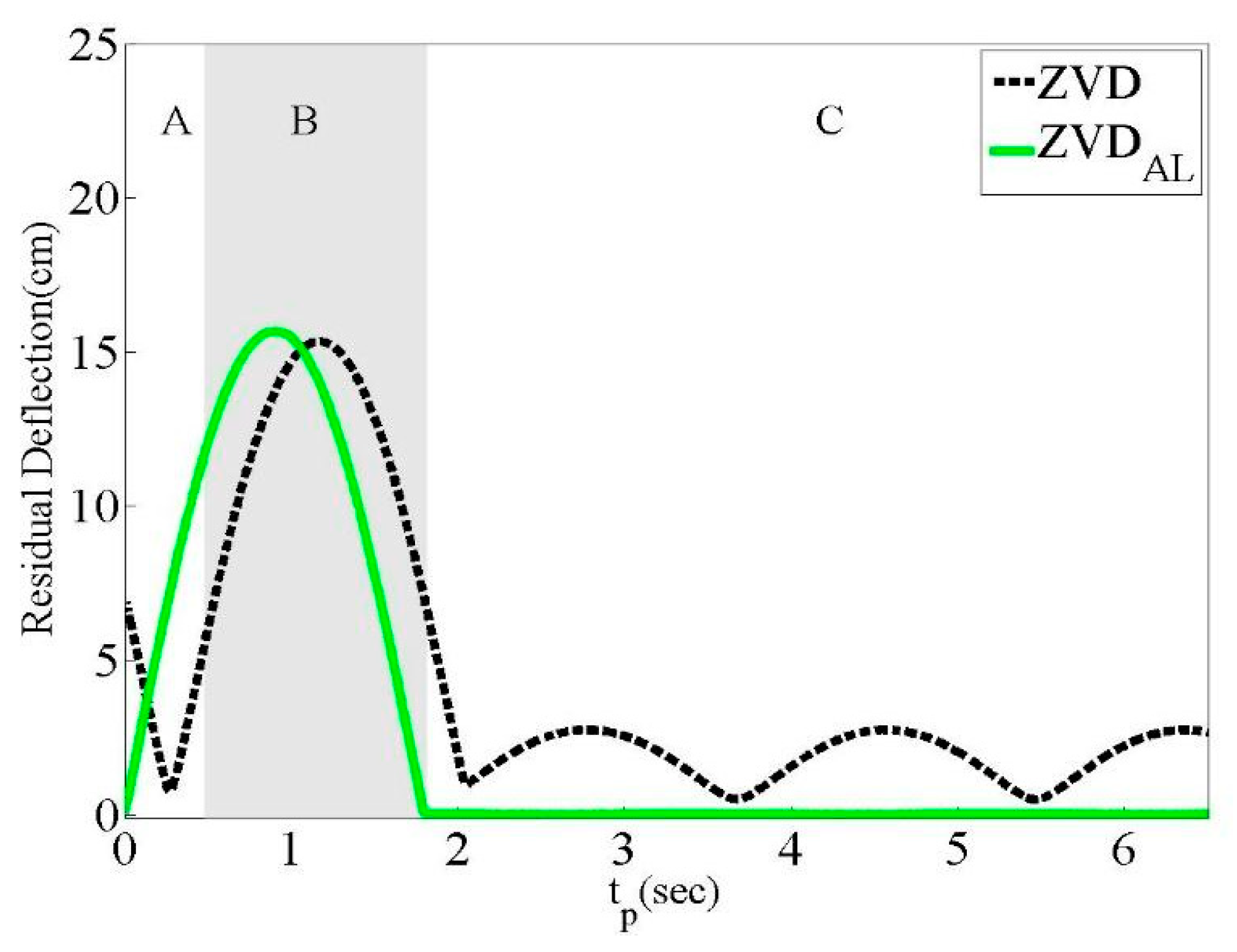
Figure 8 depicts the residual deflection reduction performance with respect to the command completeness of the ZVD and ZVDAL shapers as a function of the duration time () with fixed values of remaining modeling parameters. In region A, illustrated as the short commands that do not reach the set-point velocity level, both shapers exhibit residual deflection. In region B, called the interference commands, large residual deflections were observed. In region C, indicated as the long commands for which the region is not affected by the duration time, the ZVDAL shaper exhibits a much better residual reduction performance than the ZVD shaper.
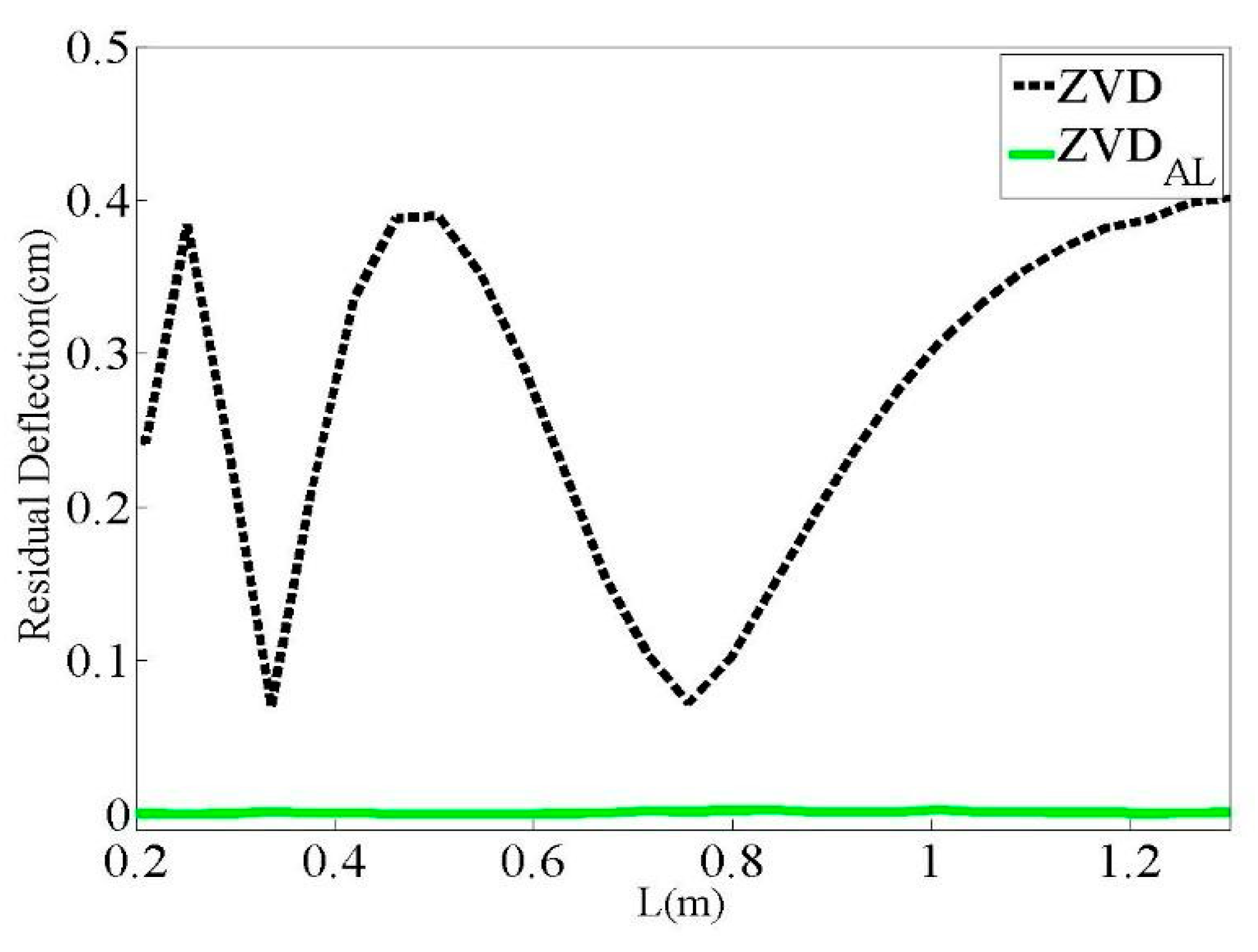
Figure 9 presents a comparison of the residual deflection with the long command for the ZVDAL and ZVD shapers according to the cable length (). While the ZVDAL shaper has no effect on the cable length variation with zero residual deflection, the ZVD shaper cannot cope with the cable length variation, as expected.
Next, numerical simulations of the residual deflection corresponding to each parameter range of the input shaper were conducted. As a result, a residual deflection graph was provided after applying the variables that are modeled when designing the input shaper to a real system. The robustness against modeling errors in the real system was evaluated using the parameter values specified in Table 1. The acceleration, deceleration, and system frequencies shown in the ramp-shaped input command graph were used.
Figure 10 shows a comparison of the residual-deflection reduction performances of the ZVDAL and ZVD shapers regarding and ranges of 0.3~0.5 m/s2. The residual deflection of the ZVDAL shaper was zero over the entire region, unlike the performance of the ZVD shaper. At = , which forms the symmetric velocity profile, there is no residual deflection when the effect of acceleration and deceleration is cancelled in the ZVDAL shaper, so both shapers have the same impulse time.
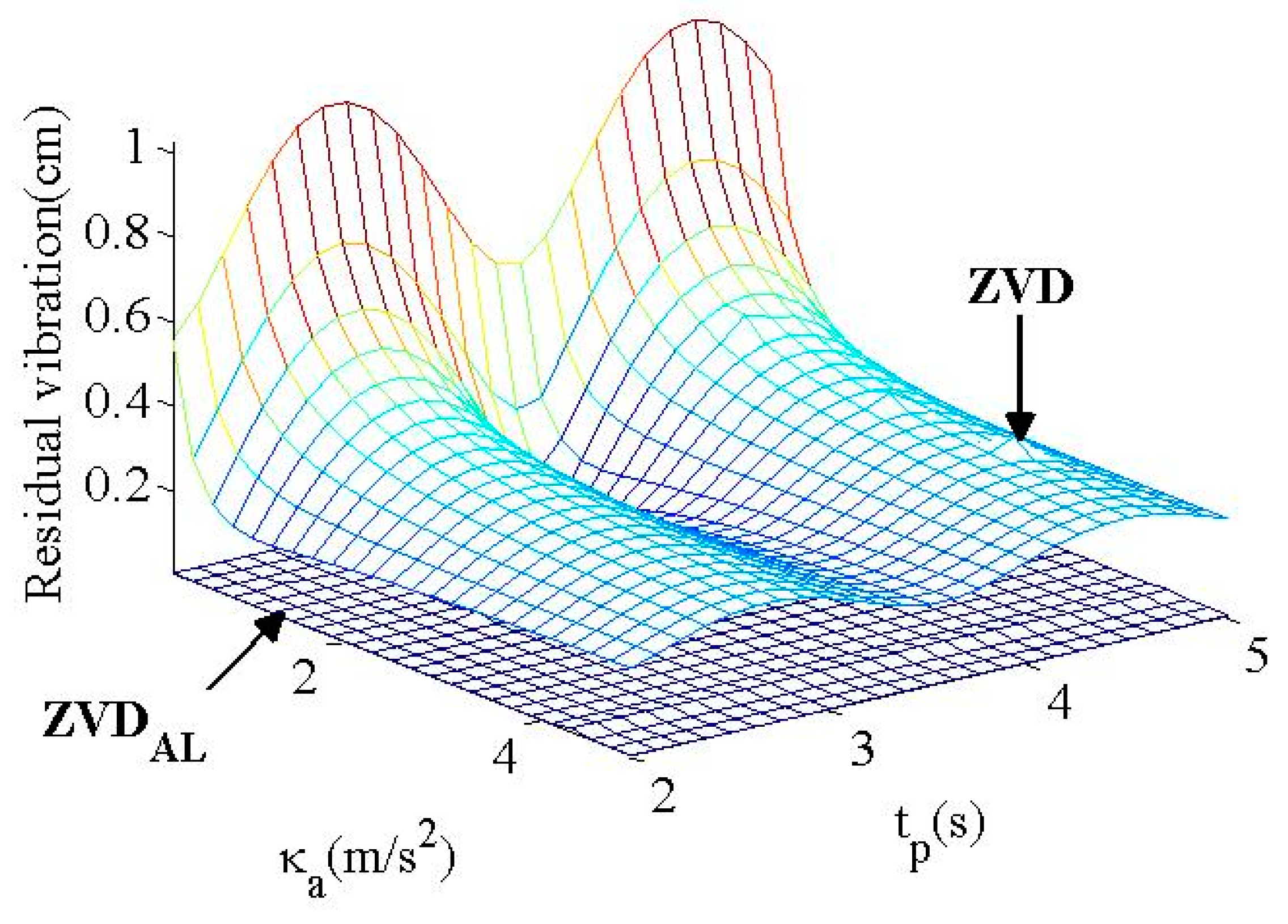
Figure 11 presents a comparison of the residual deflection reduction performances of the ZVDAL and ZVD shapers with respect to acceleration () and . The ranges of and were set as 0.3~5 m/s2 and 2~5 s, respectively. Unlike the ZVD shaper, the ZVDAL shaper exhibited zero residual deflection across the entire evaluation region. Therefore, the ZVDAL shaper can be effectively utilized with a high natural frequency for a short duration for acceleration-limit actuators. Meanwhile, the deflection reduction performance of the ZVD shaper could not be predicted because it produced a periodic deflection magnitude according to .
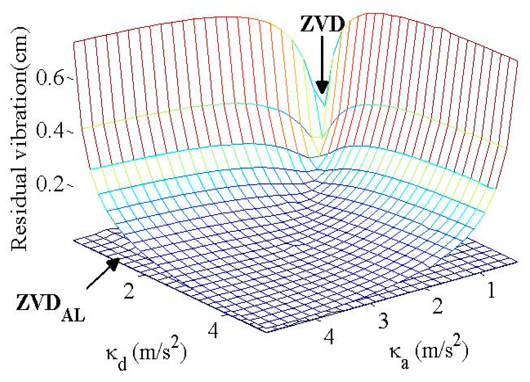
Figure 12 presents the robustness of the ZVDAL and ZVD shapers with respect to the acceleration () and string length (L), where and = 0.8 The ZVDAL shaper exhibited a better residual deflection reduction than the ZVD shaper in the entire evaluation region. At = = 1, which is in the case of no modeling errors, the ZVDAL shaper produces zero residual deflection, unlike the ZVD shaper. Therefore, the ZVDAL shaper is more robust against system modeling errors than the ZVD shaper.
3.2. EIAL Performance Evaluation
The EIAL shaper was compared with the conventional EI shaper via evaluation of the deflection reduction performances with respect to the duration, actuator parameters, and system modeling errors considering the parameter values in Table 1. With the allowable deflection level, the deflection reduction performances of the EIAL and EI shapers were evaluated as a function of the duration, cable length variation to the range of duration, and parameter modeling errors of the shapers and system.
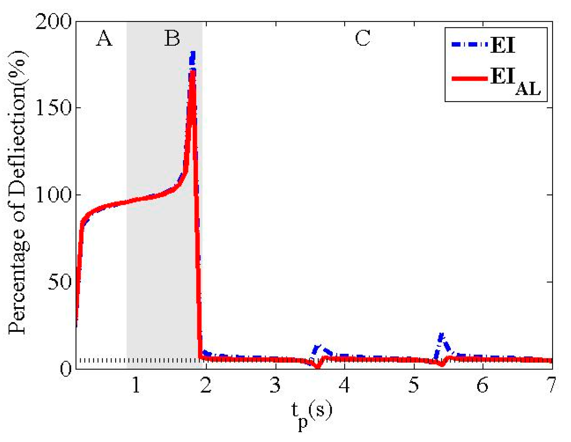
Figure 13 shows the residual deflection reduction performances of the EI and EIAL shapers with respect to the pulse duration () and an allowable deflection percentage of 5%. In regions A and B, the residual deflection is large because the shaped input command in both robust shapers is not fully generated due to the short duration. In region C, after approximately 2 s, the EIAL shaper exhibited a slightly better deflection reduction performance than the EI shaper and maintained the deflection percentage of 5%.
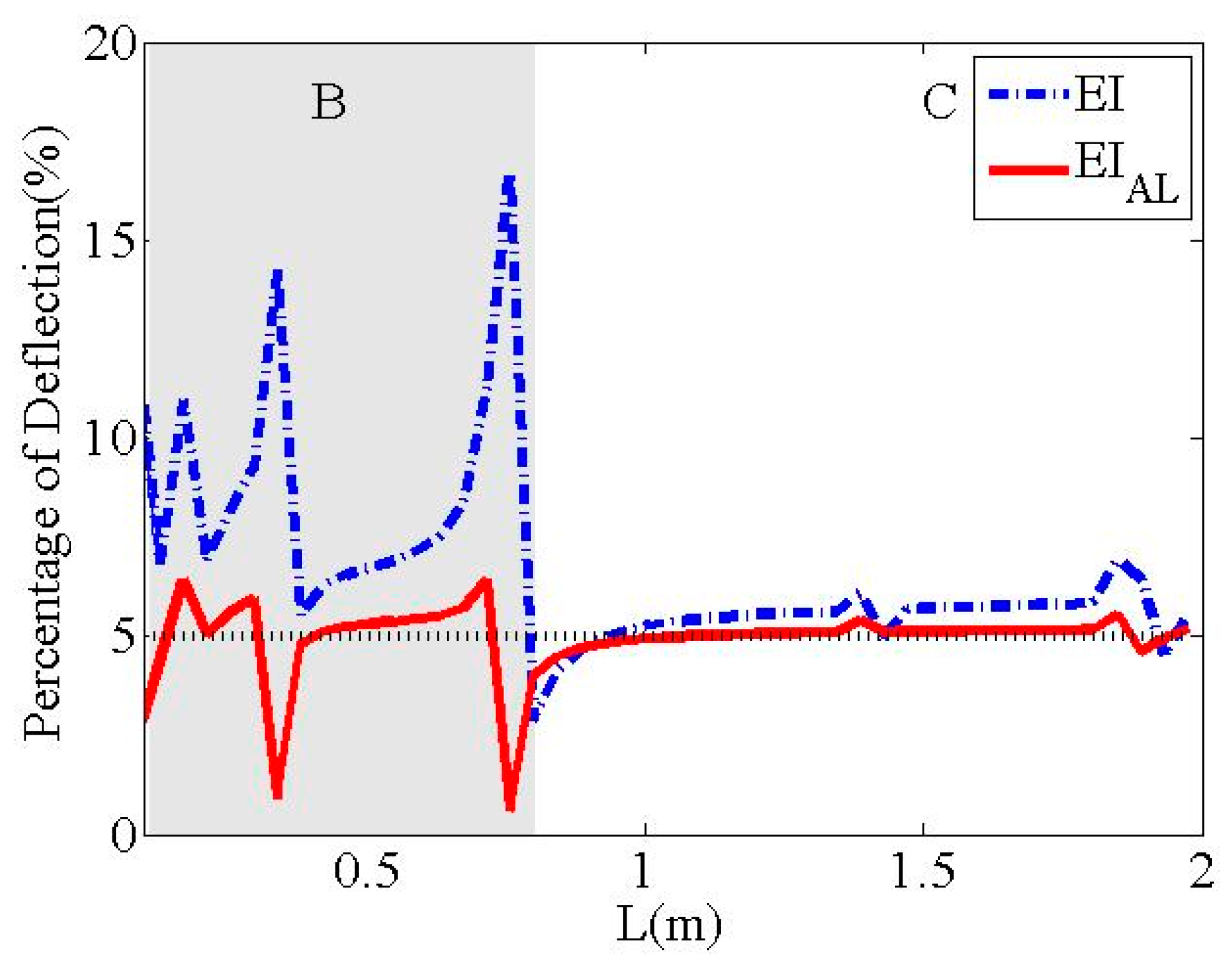
Figure 14 presents the residual deflection reduction performances in the interference and long commands of the EIAL and EI shapers as a function of the cable length (), except for the region of short commands. In region B, the EIAL shaper produced a deflection magnitude of less than 6% under the allowable deflection of 5%, while the EI shaper had a large residual deflection because the acceleration limit of the actuators was not considered. In region C, the EIAL shaper produced an acceptable residual deflection, whereas the EI shaper exhibited a slightly higher residual deflection.
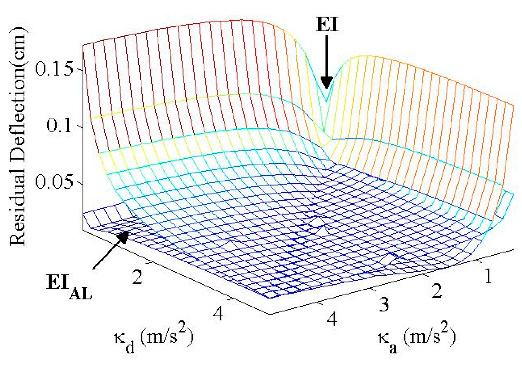
Figure 15 displays the residual deflection control performances of the EIAL and EI shapers as a function of the acceleration () and deceleration () parameters. The overall residual deflection of the EIAL shaper was approximately below 0.01 cm, while the EI shaper was affected by the acceleration and deceleration parameters of the actuators. At , the EIAL and EI shapers have identical deflection as the mutual cancellation of acceleration and deceleration velocity profiles to the EI shaper are equal. Except for the symmetric cases, the EIAL shaper indicated a better deflection control performance than the EI shaper when considering the actuator limits in the input shaper design, as expected.
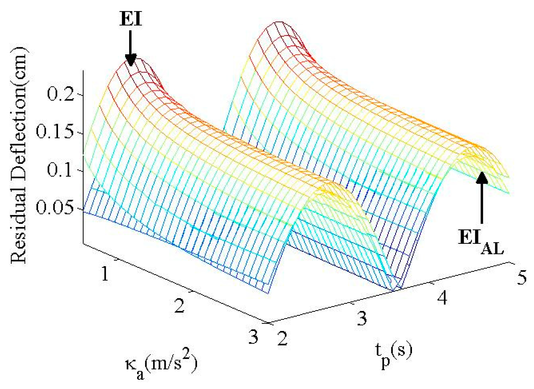
Figure 16 shows the evaluation results for the EIAL and EI shapers as functions of acceleration () and duration (). Because a certain level of residual deflection was allowed, both input shapers produced comparable residual deflections, as shown in Figure 12 and Figure 13. The EI shaper exhibits a slightly larger deflection in the case of a small acceleration parameter () than the shaper, as indicated in Figure 14.
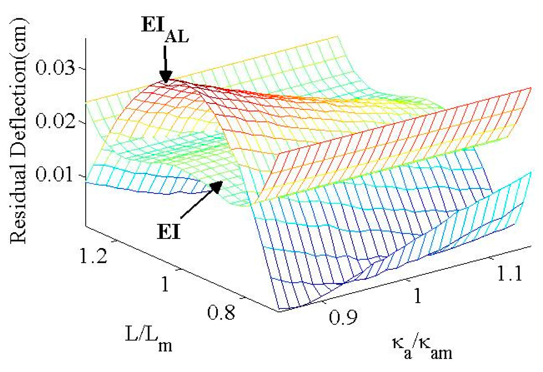
Figure 17 shows the robustness of the EIAL and EI shapers as functions of the system cable length () and acceleration parameter (), considering the values listed in Table 1. The EIAL shaper produced a hump shape with two zero-deflection locations, whereas the EI shaper exhibited a slightly larger deflection throughout the evaluation range.
The numerical evaluation showed that the ZVDAL and EIAL shapers exhibited better deflection control performances than the ZVD and EI shapers in terms of modeling uncertainties and operational parameters under acceleration- and deceleration-limit actuators. At , the ZVDAL and EIAL shaped commands were equivalent to ZVD and EI shaped commands and residual oscillations were absent. However, the condition (Equation (7)) associated with the time locations for both proposed shapers should be satisfied to prevent collapse of the shaped command profile. Further, the ZVDAL and EIAL shapers require a relatively long duration time (, as assumed in Equation (27). A comparison with ideal ZVD and EI shapers shows that from a practical viewpoint, ZVDAL and EIAL shapers are advantageous for industrial applications involving acceleration- () and deceleration- () limited actuators and modeling uncertainties (L).
4. Experimental Verification
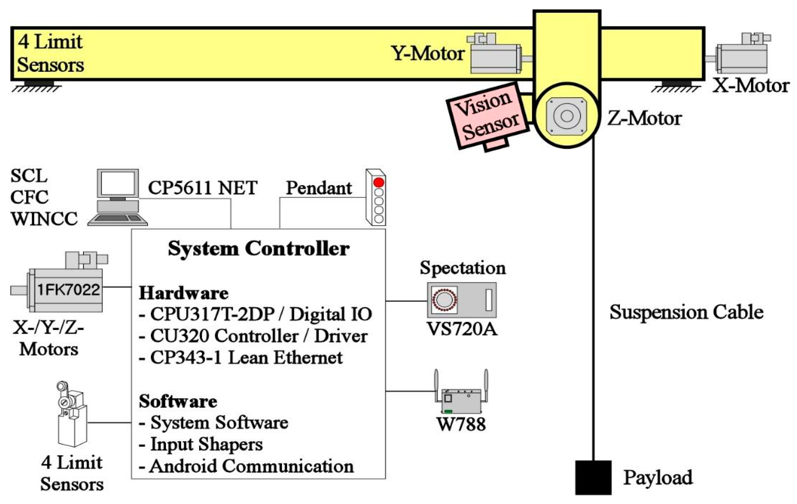
As described in this section, the control performances of the proposed ZVDAL and EIAL shapers were experimentally compared with those of ZVD and EI shapers for robustness to the uncertainties of the system and actuator parameters. The mini bridge crane in Figure 18 has dimensions of 1.3 m (length) × 0.75 m (width) × 1.5 m (height). Figure 19 shows the hardware and software components of the mini bridge crane used for the experimental verification. Among the hardware components, a programmable logic controller (PLC) was connected to a computer via a wireless local area network to implement the proposed algorithm. The velocity command generated by the PLC is transmitted to the bridge and trolley motor drives. The drive uses an incoming command as the velocity-setting point of the motor. The motor drive used a synchronous AC motor constituting a communication module and a control driver. The system software of the mini bridge crane was programmed using CFC, SCL, and WinCC Flexible 2007 software with the functions of uploading and downloading the experimental data. The magnitude of the payload oscillation was measured using a vision program with a VS720-series vision sensor, which was written using Spectation® software.
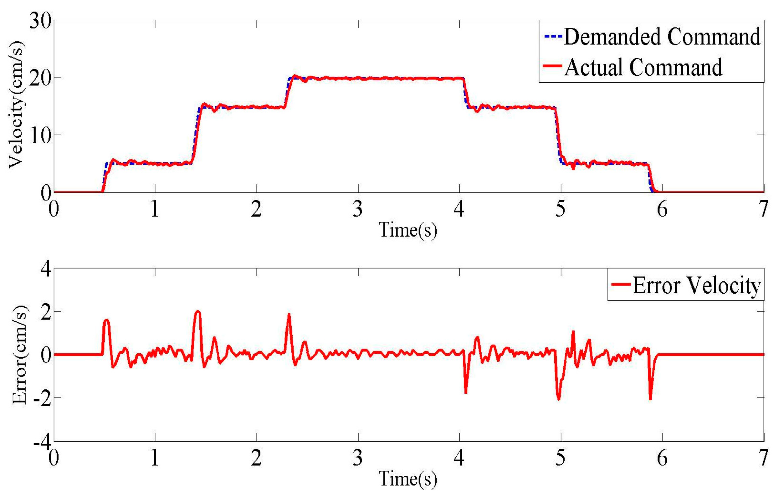
To confirm the testbed performance, the actual and shaped demanded commands for the measurement of the absolute encoder signal on the AC motor are shown in Figure 20. To accurately generate the desired input command under the asymmetric acceleration and braking rates of the actuator with the proportional gain of 0.25, an integration gain of 10 ms was set in the motor control driver. For the parameters listed in Table 1, the error velocity is shown within the range of with small oscillations at the corner of the command. Therefore, the settings of the testbed and experimental input commands can be used to evaluate various input shapers.
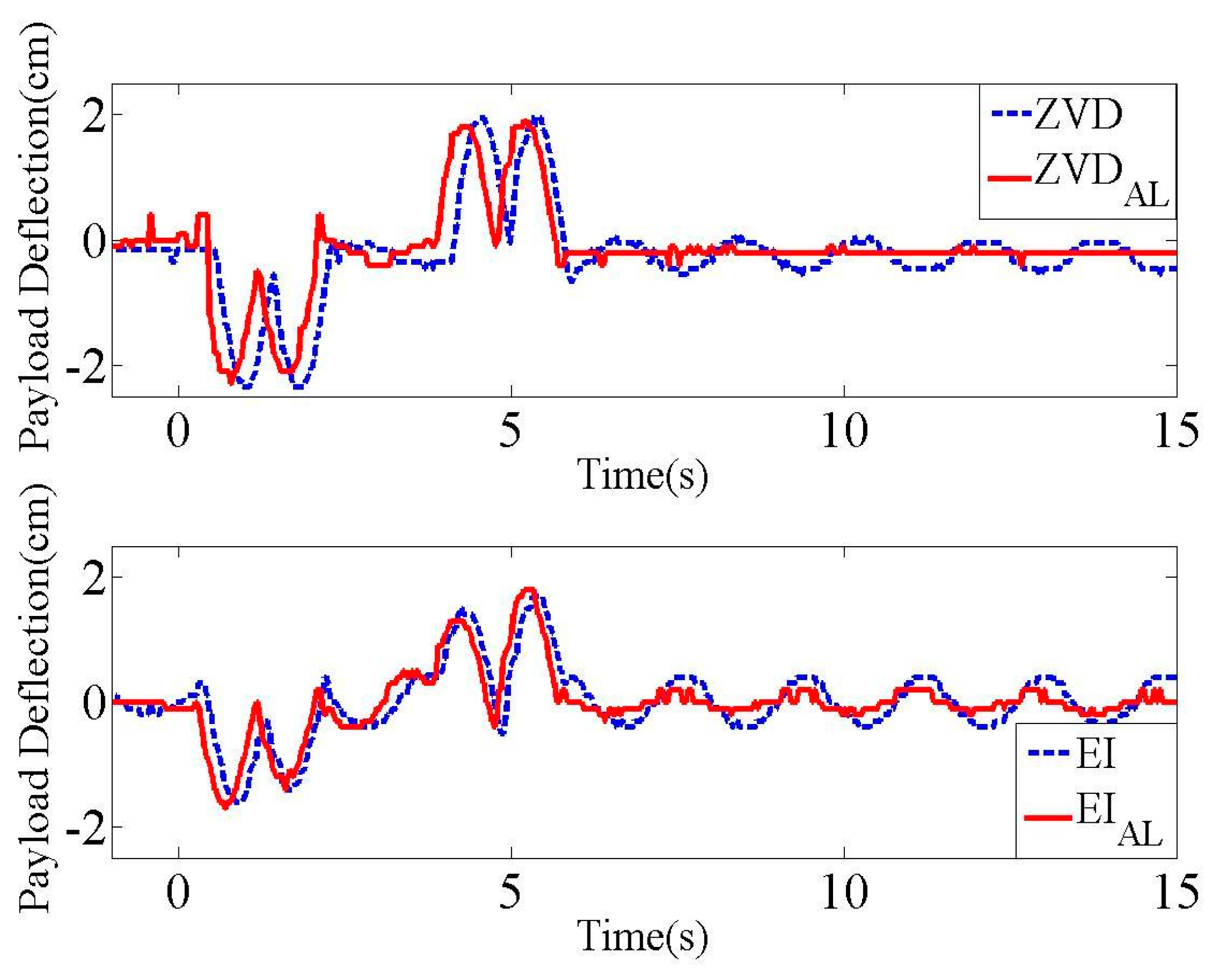
Figure 21 shows the residual deflections resulting from the actual command shown in Figure 20 while measuring the payload oscillation using the vision sensor. The ZVDAL shaper exhibited almost zero residual deflection, whereas the ZVD shaper produced a periodic residual deflection with an amplitude of 1.2 cm. However, the EIAL shaper generated an oscillation magnitude comparable to that of the EI shaper owing to the allowable residual deflection. The inclusion of actuator dynamics in the shaper design was necessary to achieve better deflection reduction.
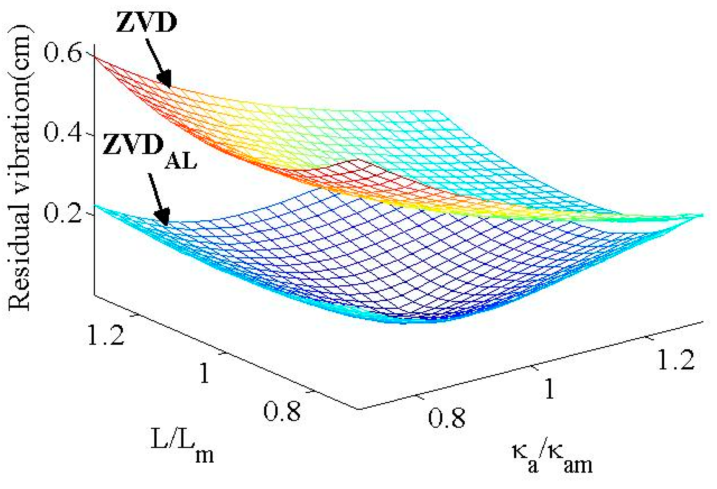
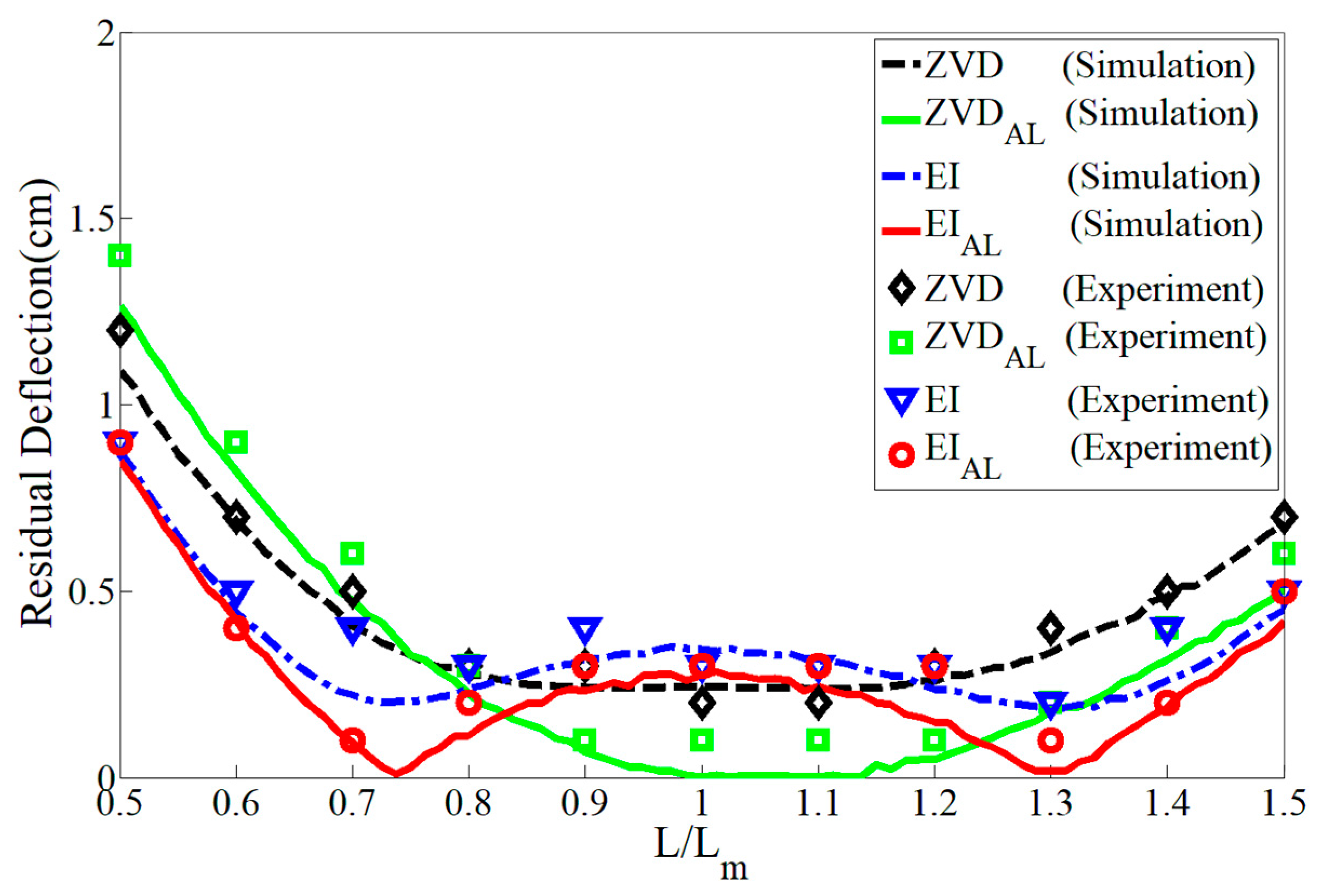
Figure 22 displays the numerical and experimental sensitivity comparison with uncertain cable length . The experimental results are presented as the average values of the data obtained from multiple experiments. The ZVDAL and EIAL shapers exhibited better robustness than the ZVD and EI shapers, which exhibit residual deflections throughout the evaluation range of . The ZVDAL shaper was characterized by zero residual deflection at whereas the ZVD shaper exhibits the same feature in the case of an ideal actuator. Furthermore, the EIAL shaper produces one hump and two zero-residual deflections, which are observed for the EI shaper in the case of an ideal actuator. Therefore, the residual deflection reduction performances of the ZVDAL and EIAL shapers are predictable, whereas the ZVD and EI shapers produce large residual deflections in the case of acceleration-limit actuators.
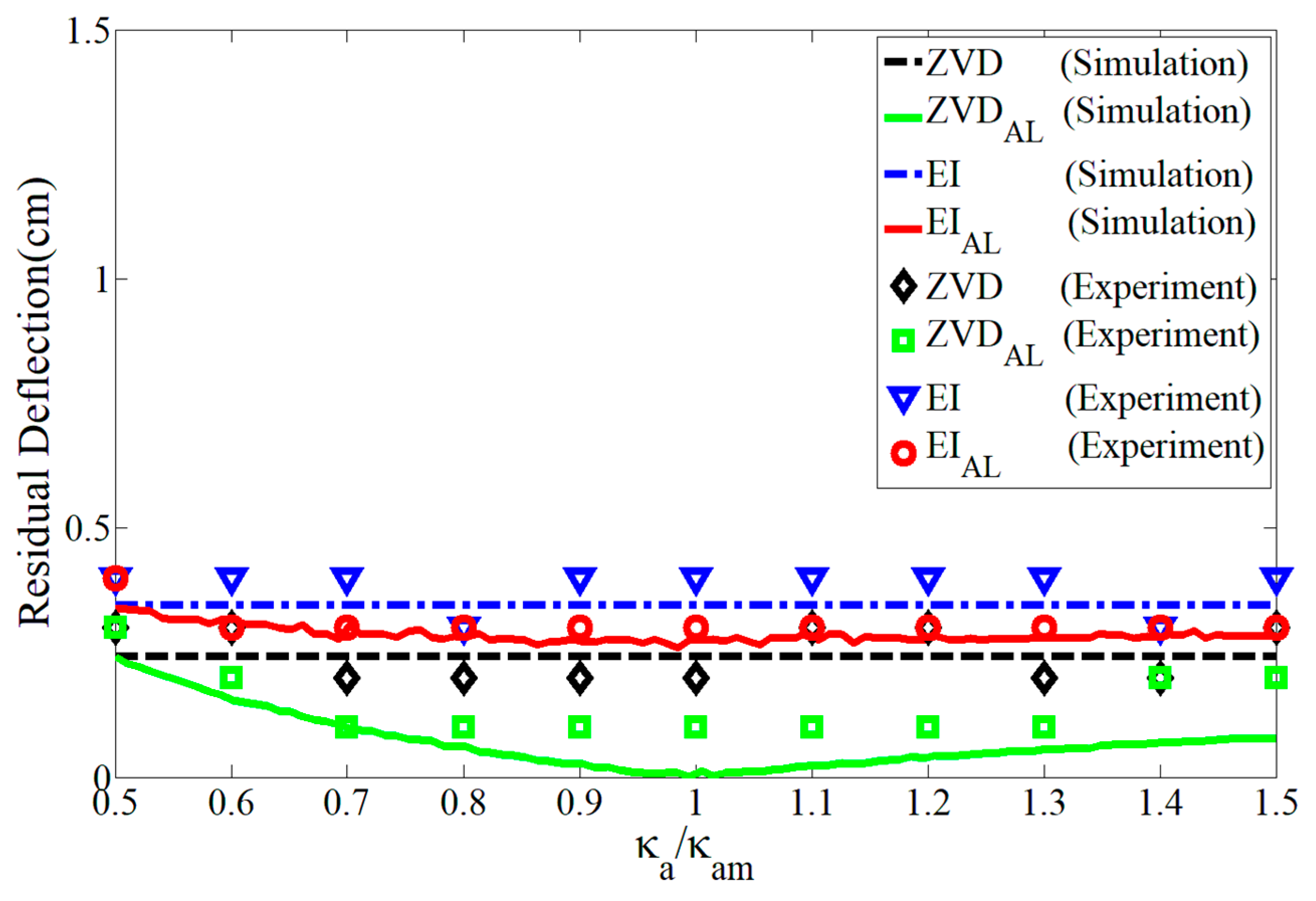
Figure 23 depicts the numerical and experimental robustness performances as a function of actuator parameter ratio . The classical ZVD and EI shapers are unaffected by the actuator parameter as expected. The ZVDAL shaper exhibits zero residual deflection at whereas the ZVD shaper shows large residual deflection. The EIAL and EL shapers exhibit similar residual deflection performances, characterized by the deflection allowance feature.
5. Conclusions
The nonlinearity arising from the unequal acceleration and deceleration time constants negatively affects the effectiveness of robust input shapers. Two new robust input shapers with only three impulse sequences for the oscillation reduction of a flexible system were analytically proposed to improve the robust performance of conventional robust input shapers and compensate for nonlinearity. Two robust schemes were developed analytically using the phase-vector approach with a ramp function to approximate the response of the acceleration-limit actuator. These schemes were numerically evaluated by comparing them with conventional robust input shapers. In general, the command completeness effect, residual deflection, and sensitivity of these schemes indicated better deflection reduction performance than those of conventional robust input shapers. The two proposed schemes were experimentally validated with a mini bridge crane to demonstrate that they produced less residual deflection than classical robust input shapers. With the benefit of closed-form solutions, the proposed schemes can be efficiently utilized for industrial applications with microcontrollers.
Author Contributions
Conceptualization and methodology, C.-L.K.; software, validation and formal analysis, Y.-G.S.; All authors have read and agreed to the published version of the manuscript.
Funding
This study was supported by research funds from the Chosun University (2019).
Institutional Review Board Statement
Not applicable.
Informed Consent Statement
Not applicable.
Data Availability Statement
Data are contained within the article.
Conflicts of Interest
The authors declare no conflict of interest.
References
- Peng, K.C.C.; Singhose, W. Low-oscillation command switch-times for relay-driven cranes with asymmetrical acceleration and deceleration. In Proceedings of the 9th Asian Control Conference, Istanbul, Turkey, 23–26 June 2013; pp. 1–6. [Google Scholar] [CrossRef]
- Vaughan, J.; Maleki, E.; Singhose, W. Advantage of using command shaping over feedback for crane control. In Proceedings of the 2010 American Control Conference, Baltimore, MD, USA, 30 June 2010–2 July 2010; pp. 2308–2313. [Google Scholar]
- Youm, W.; Jung, J.; Park, K. Vibration reduction control of a volic coil motor(VCM) nano scanner. In Proceedings of the 7th IEEE Conference on Nanotechnology, Hong Kong, China, 2–5 August 2007; pp. 520–523. [Google Scholar]
- Parker, G.; Groom, K.; Hurtado, J.; Feddema, J.; Robinett, R.; Leban, F. Experimental verification of a command shaping boom crane control system. In Proceedings of the American Control Conference ACC, SanDiego, CA, USA, 2–4 June 1999; pp. 86–90. [Google Scholar]
- Khalid, A.; Huey, J.; Singhose, W.; Lawrence, J. Human operator performance testing using an input-shaped bridge crane. J. Dyn. Syst. Meas. Control 2006, 128, 835–841. [Google Scholar] [CrossRef]
- Singhose, W.; Kim, D.; Kenison, M. Input shaping control of double-pendulum bridge crane oscillations. J. Dyn. Syst. Meas. Control 2008, 130, 034504. [Google Scholar] [CrossRef]
- Smith, O.J.M. Feedback Control Systems; McGraw-Hill: New York, NY, USA, 1958. [Google Scholar]
- Singer, N.C.; Seering, W.P. Preshaping command inputs to reduce system vibration. J. Dyn. Syst. Meas. Control 1990, 112, 76–82. [Google Scholar] [CrossRef]
- Singhose, W.E.; Seering, W.P.; Singer, N. Residual vibration reduction using vector diagrams to generate shaped inputs. J. Mech. Des. 1994, 116, 654–659. [Google Scholar] [CrossRef]
- Dainelson, J.; Lawrence, J.; Singhose, W. Command shaping for flexible systems subject to constant acceleration limits. J. Dyn. Syst. Meas. Control 2008, 130, 051011. [Google Scholar] [CrossRef]
- Sung, Y.-G.; Jang, W.-S.; Kim, J.-Y. Negative input shaped commands for unequal acceleration and braking delays of actuators. J. Dyn. Syst. Meas. Control 2018, 140, 094501. [Google Scholar] [CrossRef]
- Bradley, T.; Danielson, D.; Lawrence, J.; Singhose, W. Command shaping under nonsymmetrical acceleration and braking dynamic. J. Vib. Acoust. 2008, 130, 054053. [Google Scholar] [CrossRef]
- Lawrnence, J. Crane Oscillation Control: Nonlinear Elements and Educational Improvements. Ph.D. Thesis, Georgia Institute of Technology, Atlanta, Georgia, 2006. [Google Scholar]
- Sung, Y.-G.; Ryu, B.-J. On-off shaping commands for asymmetrically delayd second-order actuators. J. Electr. Eng. Technol. 2019, 14, 2205–2216. [Google Scholar] [CrossRef]
- Sorensen, K.; Singhose, W. Oscillatory effects of common hard nonlinearities on systems using two-impulse ZV input shaping. In Proceedings of the Americal Control Conference, New York, NY, USA, 11–13 July 2007; pp. 5539–5544. [Google Scholar]
- Sorensen, K. Operational Performance Enhancement of Human Operated Flexible Systems. Ph.D. Thesis, Georgia Institute of Technology, Atlanta, Georgia, 2008. [Google Scholar]
- Lawrence, J.; Falkenberg, M.; Singhose, W. Input shaping for a exible, nonlinear, one-link robotic arm with backlash. In Proceedings of the Japan-USA Symposium on Flexible Automation, Denver, CO, USA, 18–23 July 2004. [Google Scholar]
- Lawrence, J.; Singhose, W.; Hekman, K. Friction-compensating command shaping for vibration reduction. J. Vib. Acoust. 2005, 127, 307–314. [Google Scholar] [CrossRef]
- Singhose, W.; Banerjee, A.; Seering, W. Slewing flexible spacecraft with deflection-limiting input shaping. J. Guid. Control Dyn. 1997, 2, 291–298. [Google Scholar] [CrossRef]
- Singhose, W.E.; Seering, W.P.; Singer, N.C. Input shaping for vibration reduction with specified insensitivity to modeling errors. In Proceedings of the Japan-USA Symposium on Flexible Automation, Boston, MA, USA, 7–10 July 1996. [Google Scholar]
- Singh, T.; Vadali, S.R. Robust time-optimal control—Frequency domain approach. J. Guid. Control Dyn. 1994, 17, 346–353. [Google Scholar] [CrossRef]
- Tuttle, T.D.; Seering, W.P. Experimental verification of vibration reduction in flexible spacecraft using input shaping. J. Guid. Control Dyn. 1997, 20, 658–664. [Google Scholar] [CrossRef]
- Singhose, W.E.; Derezinski, S.; Singer, N. Extra-insensitive input shapers for controlling flexible spacecraft. J. Guid. Control Dyn. 1996, 19, 385–391. [Google Scholar] [CrossRef]
Figure 1.
Sensitivity comparison for input shapers.

Figure 2.
Effects of ideal and acceleration-limit actuators. (a) Ideal actuator effect. (b) Acceleration-limit actuator effects.
Figure 2.
Effects of ideal and acceleration-limit actuators. (a) Ideal actuator effect. (b) Acceleration-limit actuator effects.

Figure 3.
Equivalent transformation. (a) Original command process. (b) Equivalent command process.

Figure 4.
Pendulum system.

Figure 5.
Segmentation of a start command. (a) Range division. (b) Segmented profile.

Figure 6.
Vector diagram of ZVDAL shaper.

Figure 7.
Vector diagram of EIAL shaper.

Figure 8.
ZVDAL command completeness effect due to .

Figure 9.
ZVDAL command completeness effect to .

Figure 10.
Residual deflection of ZVDAL shaper to and .

Figure 11.
Residual deflection of ZVDAL shaper to and .

Figure 12.
Sensitivity of ZVDAL shaper to L and .

Figure 13.
EIAL command completeness effect to .

Figure 14.
EIAL command completeness effect to .

Figure 15.
Residual deflection of EIAL shaper to and .

Figure 16.
Residual deflection of EIAL shaper to and .

Figure 17.
Sensitivity of EIAL shaper to L and .

Figure 18.
Mini bridge crane.

Figure 19.
Hardware configuration.

Figure 20.
Experimental input commands on the x−axis.

Figure 21.
Experimental deflection responses of the payload.

Figure 22.
Comparison of sensitivity to .

Figure 23.
Comparison of sensitivity to .


Table 1.
Modeling parameter values for ZVDAL and EIAL shapers.
| 0.8 m | 1 | 1.5 | 0.2 | 3.5 s | 0.5% |
Disclaimer/Publisher’s Note: The statements, opinions and data contained in all publications are solely those of the individual author(s) and contributor(s) and not of MDPI and/or the editor(s). MDPI and/or the editor(s) disclaim responsibility for any injury to people or property resulting from any ideas, methods, instructions or products referred to in the content. |
© 2023 by the authors. Licensee MDPI, Basel, Switzerland. This article is an open access article distributed under the terms and conditions of the Creative Commons Attribution (CC BY) license (https://creativecommons.org/licenses/by/4.0/).
Share and Cite
MDPI and ACS Style
Kim, C.-L.; Sung, Y.-G. Robust Input Shapers for Acceleration-Limit Actuators. Appl. Sci. 2023, 13, 12499. https://doi.org/10.3390/app132212499
AMA Style
Kim C-L, Sung Y-G. Robust Input Shapers for Acceleration-Limit Actuators. Applied Sciences. 2023; 13(22):12499. https://doi.org/10.3390/app132212499
Chicago/Turabian StyleKim, Chang-Lae, and Yoon-Gyung Sung. 2023. "Robust Input Shapers for Acceleration-Limit Actuators" Applied Sciences 13, no. 22: 12499. https://doi.org/10.3390/app132212499
Note that from the first issue of 2016, this journal uses article numbers instead of page numbers. See further details here.