Review

A Review of the Network Arch Bridge

by
Alexandra Denisa Danciu
1,*,
Ștefan I. Guțiu
1,
Cătălin Moga
2,
Mihai L. Dragomir
1,
Mădălina Ciotlăuș
1 and
Vladimir Marusceac
1
1
Department of Railways, Roads and Bridges, Technical University of Cluj-Napoca, 400641 Cluj-Napoca, Romania
2
Department of Structures, Technical University of Cluj-Napoca, 400641 Cluj-Napoca, Romania
*
Author to whom correspondence should be addressed.
Appl. Sci. 2023, 13(19), 10966; https://doi.org/10.3390/app131910966
Submission received: 25 August 2023 / Revised: 30 September 2023 / Accepted: 2 October 2023 / Published: 4 October 2023
(This article belongs to the Special Issue Bridge Structural Analysis)

Abstract

:
The network arch bridge (NAB) is a new structural form of arch bridge that was devised 60 years ago by the Norwegian engineer Per Tveit, who is now prof. dr. docent emeritus at the University of Agder, Norway. The network arch is a tied-arch (also known as a bowstring-arch) bridge that combines the benefits of tied-arch bridges and trusses in a single system. While in a classical tied arch, the hangers are vertical, in a network arch, the suspension of the deck to the arch is ensured through a network of inclined hangers that intersect each other at least twice. Thus, the core of the NAB is the hanger arrangement that minimizes the bending moment in the arch to very small values, leading to compression in the arch. Compression with only small bending leads to very slender cross-sections for the elements of the bridge, and deep reductions in terms of materials used and economic and environmental costs. This paper reviews the research into the structural form proposed by Per Tveit and extended by researchers and engineers worldwide. The research methodology included bibliometric literature research, obtained by interrogating the ISI Web of Science (WoS) database and the cited references from the articles on WoS. While the first structural form of a network arch is still in use today and it has proven to be a good idea for spans around 100–120 m, engineers worldwide devised new bridge cross-sections. A brief view of the types of bridge cross-section in use today is given, with details about the bridges chosen as representative. Using analysis of Prof. Tveit’s map, Structurae database and literature review, a database of the network arches around the world was created, emphasizing the development of network arches from the perspectives of continental distribution, opening year, number of structures in different structural forms, and bridge purposes. The structural form was assessed from the perspective of materials used for the arch and the tie, span, purpose and number of lanes, the presence/absence of upper wind-bracings and arch disposition in the vertical plane. In the last part of this review, the newest research into the development of the network arch is discussed. In the past 15 years we have seen an acceleration in network arch development from multiple perspectives: new materials used, such as glulam for the arch or carbon fiber-reinforced plastic for the hangers; span lengths of 250 m and 380 m for large bridge widths; architectural constraints that lead to the outward inclination of the arch, that is pleasing to the eye, but difficult to address from an engineering perspective; the most slender arch bridge in the world, with very slender cross-sections for the arch and the tie.

1. Introduction

As professor Per Tveit states in refs. [1,2], while working on his master’s thesis in 1955, he came up with the idea of an arch bridge with inclined hangers that crossed each other at least twice. He gave the new structure the name “Network arch” and it has been the centerpiece of his research for years since. Professor Tveit’s first structure was the network arch at Steinkjer in Norway, completed in 1963, with a carriageway of 6 m and a span of 80 m. In the 67 years that have passed since he had the idea, network arches spread throughout the globe and now exist in more than 30 countries. A map [3] was developed and constantly updated with locations of newly built network arch bridges (referred to as NAB in the paper). As the authors found during the research conducted for the current state of the art, many network arch structures are not yet included in the map at ref. [3].
One could consider that NABs are like Nielsen bridges, but some differences should be considered. O.F. Nielsen [4] designed arch bridges with inclined hangers with or without an intersection point along the tie or the arch. The sloping of the hangers in his proposal reduces the bending in the chord [5] because a load on the left side of the span activates the hangers sloping to the right, equalizing the load on the arch. Nielsen did not build arch bridges with hangers crossing each other, but in a patent from 1926, he showed such a bridge, with some of the hangers crossing once. Figure 1a shows a Nielsen bridge built in 1933 in France, and Figure 1b a drawing in Nielsen’s patent from 1926. NABs, as stated in the definition, are arch bridges with sloping hangers that cross each other at least twice. Network arches have very good stiffness, a better distribution of the bending moments along the arches compared to arches with vertical hangers, and can be designed as the world’s most slender arch bridges. To this point, as stated in refs. [5,6], the world’s most slender NAB is Brandanger Bridge in Norway. The first NABs proposed and studied followed Tveit recommendations [1] to have a steel arch and a concrete tie, with a circular constant curvature arch. Later, researchers started to investigate the behavior of NABs with the arch having different curvatures, or the arch part of a parabola and the tie a composite section; also, for the arch, other materials such as timber or concrete were used, as seen later in the paper.

1.1. Research Purpose

Given the above-described context, the purpose of this research was to investigate the development of the network arch bridge from the idea proposed by Prof. Tveit to the structures built in the past 15 years. The main research questions this study sought to answer were: “Is the Network Arch Bridge suitable for small spans up to hundreds of meters for all type of bridges, and can it safely be improved in terms of structural form and materials used to reduce the construction impact on the environment?”.
To address the above-mentioned questions, the search began with the identification of literature published on the subject of the network arch bridge. The first set of data used in the analysis was obtained from ISI Web of Science Database. The cited references from the first set of data were identified next.
To create the network arch bridge structures database, the resources used were the map created by Prof. Tveit [3], the Structurae database [7] and the structures mentioned in the literature review.
The identified scientific papers were divided following the proposed structure of the paper. First, an introduction into the network arch and the proposed scientific outcome of the paper are given. The next part presents Per Tveit’s vision of the optimal NAB and the research conducted following his recommendations. The third chapter details other structural types proposed for NABs, the research conducted, details regarding the materials used, and the innovations in design. The third chapter also presents a summary of the NAB database created, highlighting the achievements made so far. The fourth chapter presents other research conducted, subdivided into: the development of the NAB in timber; NABs used as pedestrian bridges; the developments in the stability analysis of the network arch; new research dealing with the hanger arrangement, including genetic algorithms used to generate the geometry of the network arch; and other research published, presenting structures built around the globe.
The responses to the research questions are shown in the conclusions section, together with future directions in the development of the network arch and its potential impact on the future of the construction industry.

1.2. Research Methods

The research methods used in the study take into account the main objective of the research. The data collection for the literature review started with the interrogation of the ISI Web of Science (WOS) database with certain keywords specific to the subject of the paper, the screening of the papers and removal of irrelevant ones. Next, the cited references not indexed in WOS were found and screened to remove irrelevant papers. After the collection of all of the references, a classification based on subject and year of publication was performed. Parts of the research papers were supervised and undertaken under the guidance of Prof. Tveit, and the other research papers were classified according to the structure of the present review, already discussed in the previous subsection. This review was not limited to only WOS papers, as most of the research conducted in the early years of network arch development was published in the form of master’s and doctoral theses and public works of Prof. Tveit. In a discussion with Prof. Tveit, he expressed his desire for open access to all publications on the network arch bridge.
The data collection flow of the research is shown in Figure 2.

2. Per Tveit Vision and Conception of the Network Arch Bridge

Professor Tweit’s recommendations in designing the network arch [1] are oriented in the direction of the best efficiency-to-cost ratio. This chapter is based on Per Tveit’s vision of the optimal shape of network arches [2].
The arch should be part of a circle [1], and the curvature of the arch near the supports should be part of another circle with a reduced radius, Figure 3 [5], so that increased cross sections are shorter. It should be mentioned here that up until the paper published in 2019 [5], the recommendation given was for the curvature near the supports to have a radius of about 80% of the radius of the curvature of the arch [1].
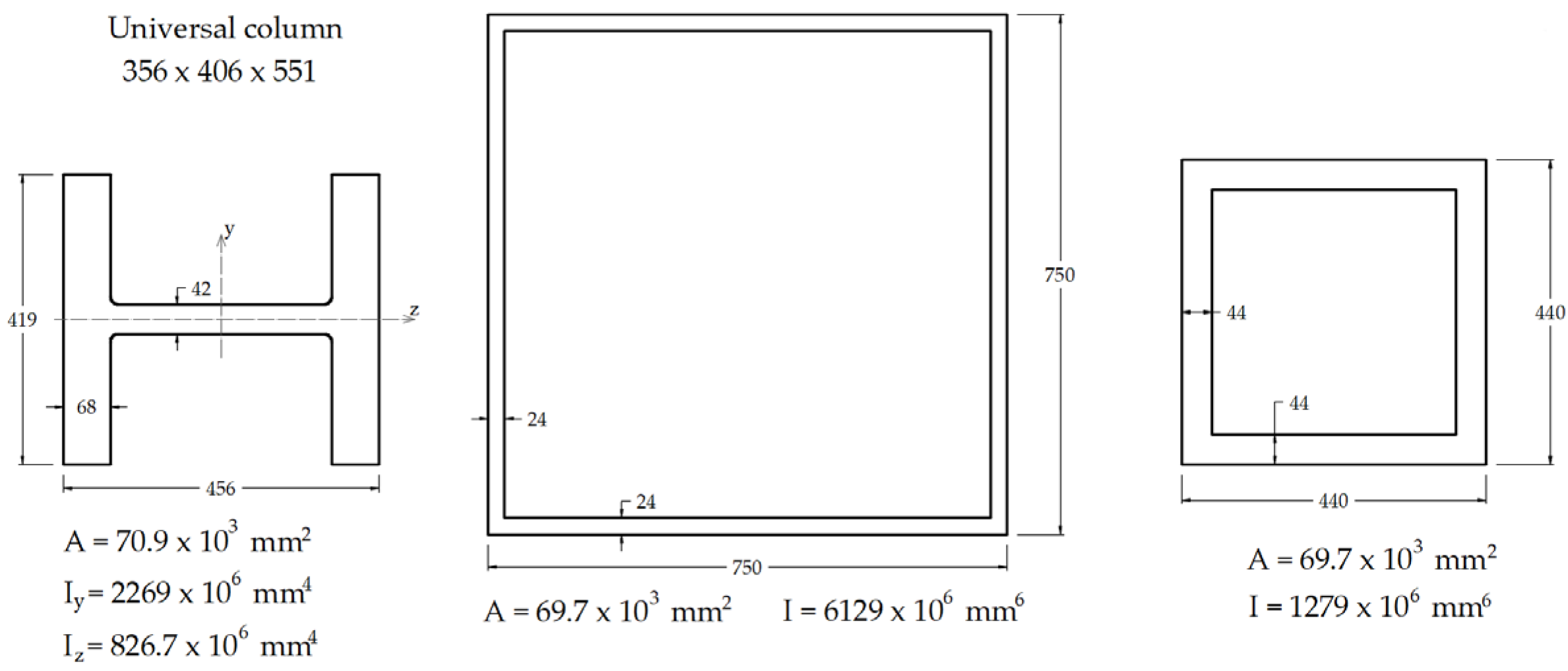
The cross-section for the arch should be a universal column or a similar American wide flange beam [1,2] due to the slim-look universal columns give to the network arch, less welding and simpler details. In the design of the network arches by Teich and Wendelin for their graduation thesis [8], the cross-section chosen was a universal column (UC) 356 × 406 × 551 made of steel with a yield stress of 430 N/mm2, Figure 4 [1]. In the same figure, a comparison with two box sections with the same area is presented. The comparison shows that the box cross-section in the middle is 64% wider than the universal column, and it has a moment of inertia 2.7 times higher. The box section at the right, even though it visually has an effect similar to that of the universal column, is considered by Per Tveit to be impractical compared to the universal column; the UC requires a smaller amount of welding, with simpler details and smaller dimensions.
According to ref. [2], when the arches are less than 15 m apart, the tie should be a concrete slab with edge beams spanning between the arches. The two edge beams are to be on the same plane as the plane of the arches. This solution ensures a good distribution of the concentrated loads, while the solution with crossbeams concentrates the forces. The tensile force in the tie will be taken by prestressing cables located in the edge beams. The proposed cross-section for the tie is presented in Figure 5 [2]. Transverse prestressing might be necessary for distances between the arches larger than 10 m.
For a slab made of concrete C40/50, depending on the span of the slab in the transverse direction, the necessary thickness was computed by Teich and Wendelin [8], Figure 6. They studied a two-lane road bridge with a span of 135 m, the lower chord similar to Figure 5 and the arch cross-section, the universal column in Figure 3. The necessary slab thickness is valid for the case mentioned, where the lower chords are made of prestressed concrete wide beams. The study concluded by Teich and Wendelin led to the graph in Figure 6, and is one of the tools still in use today when choosing the necessary thickness of the plate.
Under the guidance of Prof. Tveit and Prof. Wolfgang Graβe, in 2002, Uve Steinmann [9] finished designing a double-track railway NAB using the Eurocodes. The span of the railway bridge was 100 m. Steinmann’s thesis focused only on designing the bridge, but it was then used as a benchmark for the thesis of Brunn and Schanack [10], where much effort was placed on the optimization of the hanger arrangement. In ref. [10], the authors devised 850 different hanger arrangements that were compared to search for the minimum internal forces; about 100 bridges were calculated, varying the geometry of the bridge in terms of span, arch rise, number of hangers and arch curvature. One hanger arrangement proposed in ref. [10] was based on the proposal of Tveit [1] and Teich and Wendelin [8], where it was suggested that the hangers be equally spaced along the middle of the tie, while the distances decrease for one set of hangers and increase for the other set toward the end-spans of the bridge. To construct the proposed geometry, in ref. [10], an algebraic description of the geometry was found for the curvature of an ellipse. Two variables made possible the change in the hanger arrangement, the ratio between the semi-minor axis and semi-major axis of the ellipse, λ.el, Equation (1) and a coefficient representing the utilization of the ellipse, λr, Equation (2), the figure representing the utilization of the ellipse can be found in ref. [10].
λ.el = b/a,    λ.el = [0…1]
Λ.r = Δx/x.m,    λr = [0…1]
where a is the semi-major axis of the ellipse, b the semi-minor axis, and the parameter λ.el allows for an equidistant spacing of the nodes when λ.el = 0 and an extreme increase when λ.el = 1. The second parameter, λ.r, was used to exclude larger curvature changes and to ensure an equilibrated spacing between the nodes at the two ends of the arch.
Another hanger arrangement in ref. [10] is derived from ref. [1], and it is based on the idea of having equally spaced nodes along the length of the arch. The hangers slope toward the tie, intersecting the tie at different angles. The intersecting angle between the tie and the hangers has a constant change from one hanger to the next one [10]; the variables describing such an arrangement are the start angle and the angle change that can increase or decrease, Figure 7.
The radial hanger arrangement, believed to be the best in terms of stress distribution in the NAB, was studied by Teich [8] and Brunn and Schanack [10]. The idea behind this arrangement is that the bending in the arch about the horizontal axis is at a minimum if the line of thrust deviates very little from the centerline of the arch [8]. To obtain the radial hanger arrangement, the nodes were placed equally spaced along the length of the arch. The hangers slope toward the tie at different intersection angles with the tie, while the intersection angle with the radii to the arch circle has the same angle on circles concentric to the arch circle, Figure 8a. One configuration obtained using the radial arrangement, devised for a 100 m network arch with 42 hangers, is shown in Figure 8b.
Teich continued the study begun in ref. [8] for his PhD [11], where one of the main focuses of the research was the optimization of the hanger arrangement in NABs with spans varying from 100 m to 250 m; the span increase at each iteration was 25 m, and the number of hangers varied from 24 to 36, 48 and 60. Based on the hanger arrangements in ref. [10], he devised in ref. [11] five different types of arrangements and analyzed the optimal variant for several criteria with concrete recommendations on the type of hanger arrangement to choose for different spans and different numbers of hangers.
In the early 2000s, several students working with Professor Tveit or other professors interested in the subject of NAB also included in their graduation theses the calculations according to Eurocode for one variant of the NAB studied in their research. Steinmann [9] designed a double-track railway NAB with a span of 100 m; Brunn and Schanack [10] designed a double-track railway NAB with a span of 100 m; Rack [12] investigated the possibility of designing a combined road and rail network arch with a span of 160 m. Niklison [13] calculated a bridge over the Luznice River in the Czech Republic with a span of 41 m; based on the configuration of the bridge, he conducted a study varying the hanger arrangement, the number of hangers and the rise of the arch. Three new configurations for the bridge were chosen and analyzed because of this study. In 2011, Varennes [14] designed a single-track railway NAB as part of his master’s thesis. The chosen span for the bridge was 75 m, the deck was from prestressed concrete C50/60, and for the arch and hangers, high-strength steel S460 ML was chosen. The hanger arrangement was radial, and the recommendations in ref. [8] were considered for the arch curvature smaller near the ends. A comparison between the solution in a single curvature and reduced curvature was undertaken, and the conclusion drawn was that the bending moment decreases by more than 50% for reduced curvature. Da Costa, in his master’s thesis [15], studied the reliability of an NAB with a span of 180 m and a distance between the arches of 26.60 m. The cross-section of the bridge carried four lanes, two in each direction. The tie was made of steel, while the deck had a composite cross-section with crossbeams of variable heights and a concrete deck. The arches were inclined inward with an angle of 79°. As stated by the author, the Inclined arches would reduce the wind portal frames and the bracing beam lengths, thus giving a better solution in terms of stability than vertical arches [15]. As seen later in this paper, several large-span NABs with large widths of the cross-section were constructed with inward inclined arches.
The first papers presented in this section [8,9,10,11] had, as a primary purpose, the understanding of the network arch behavior when different parameters are changed; this early research stands as the primary tool in design today. In refs. [12,13,14,15], the focus of the research conducted shifted toward designing real structures and understanding if the network arch could be used for a railroad or a combined railroad and road bridge.
In Tveit’s design of the network arch, the deck is made of concrete with prestressing cables in the edge beams, and the arches and hangers are made in steel. For the deck, Tveit recommends only concrete in order to reduce the materials used to a minimum. In a number of his communications and papers [1,2,16], a comparison of steel weights in different arch bridges is presented. The arch bridges compared with the network arch have steel beams in the tie, while the network arch deck is made only in concrete. The findings in refs. [1,2,16] were that the same amount of reinforcement would be used in both vertical arches with steel beams in the tie as in the network arch with concrete edge beams. In the network arch, the plate connecting the edge beams has a recommended thickness of 18 cm to 35 cm (see Figure 6), so the amount of concrete saved if steel beams are used instead of concrete beams is very little. Overall, the reduction in cost in an optimal network arch compared to an arch with vertical hangers is between 35% to 45% per m2 of useful bridge area.

3. Network Arch Bridges of Different Structural Systems around the World

The beginnings of the research into NABs were oriented toward understanding the behavior of such structures through diploma, maste’’s and PhD theses. As the structure became popular, the focus shifted toward research into using network arches for different types of bridges than the structure proposed initially by Prof. Tveit [17,18]. Before presenting NABs of different structural systems, the authors feel it is necessary to give an insight into the first bridge designed by Per Tveit.

3.1. The Network Arch at Steinkjer

The NAB at Steinkjer in Norway is a bridge with a main span of 79.75 m, Figure 9. It has two parallel steel arches with a triangular cross-section. The cross-section can be found in ref. [7]. Tveit states in a series of papers that if universal columns had been used for the arch, the price would have been lower than for the triangular cross-section. Even so, the network arch was less costly than an alternative design proposed. The arches have a constant curvature, and the hanger arrangement is with an equidistant disposition of the hangers along the arches, while there is a constant change of slope between neighboring hangers of 1.8°. The steepest hanger has a slope of 74.4°. The tie is made of concrete, with prestressing cables in the edge beams. Even though the hangers are anchored in the concrete edge beams, due to the slight prestressing, no issue appeared at the hanger–concrete interface. What is seen as a mistake for the first NAB is the absence of railings between the traffic and the arches [18]. This mistake led to four of five of the lower ends of the hangers being bent by vehicles bumping into them, but the concrete does not appear to be damaged.
The network arch at Steinkjer is the first network arch bridge, built 60 years ago. It was at that time less costly than an alternative competing concrete arch with vertical hangers; the time that has passed since its opening stands as a testimony to the reliability of such a design.

3.2. The West Seven Street Bridge, Forth Worth, Texas

The West Seven Street Bridge, Figure 10, is the first precast network arch bridge. It was completed in 2013. Even though concrete is considered the material of choice for arches, few concrete arches have been built in modern times due to the necessity of falsework and time required. For the West Seven Street Bridge, an innovative solution was used: the concrete arches with a network hanger system were cast on their sides; after the hardening of the concrete, they were rotated to the vertical position, transported to the site and installed.
In 2015, Yousefpour et al. published a paper discussing the stresses in the first precast NAB [19]. The bridge consists of 12 arches that were cast on their sides and then transported to the location of the bridge. The arches were prestressed both in the tie and the rib. Each of the arches has a span of 49.8 m and a rise of only 7.16 m. The low rise-to-span ratio was dictated by operating requirements, that is, for the center of gravity to be as low as possible. The low rise together with aesthetics considerations led to no cross-bracings between the arches. The arches’ lateral stability is ensured by the frame created between the arches and the crossbeams. The arches were monitored using 224 vibrating wire gauges during the manipulation and posttensioning. The stresses during the two stages of posttensioning were presented. Then, after the bridge was opened, a static live load test was conducted; the conducted test showed that the stresses from the live load were relatively small compared to the construction stresses. Special attention should be given to the construction stresses and the modulus of elasticity, shrinkage of the concrete and creep that affect the stresses. Also, another important conclusion for such a structure resides in considering the uncertainties due to the hangers. Multiple hanger forces should be included in the model to obtain a reliable design. A second paper [20] describes the bridge superstructure, the instrumentation, and the efforts in the bridge from the modeling stage. The hanger arrangement chosen was for hangers parallel to each other, having an angle of 35° with the vertical plane, 26 hangers in each direction, resulting in 52 hangers for one arch.

3.3. Troja Bridge in Prague

Another unique NAB is Troja Bridge in Prague, Figure 11. Troja Bridge has a main span of 200.4 m, supported by a bowstring arch-type structure [21] with a network system for the hangers. The bridge carries four road lanes, two tram tracks and two wide pedestrian lanes for both pedestrian and cyclist traffic [22]. The rise of the arch in only 20 m, thus having a rise to span ratio of only 1/10. The arch is made of steel, with a pentagonal box cross-section that can be seen in ref. [21]. Near the sides, the arch divides into two sections, called “the legs”, that are on both sides of the tram tracks. The road and pedestrian lanes are on the “exterior” of the arch. The tie of the arch if also made of steel box in the shape of the letter omega encased in concrete. The tie carries six prestressing cables. The deck is suspended from the arch through 200 hangers of S520 grade steel [21] that were tensioned in two phases. The deck of the bridge is made of prestressed concrete: precast prestressed beams C70/85 spaced at 4000 mm [23], and a thin prestressed concrete slab C50/60 with a thickness of 28 mm. The total width of the deck is 30 m. Some aspects related to the numerical analysis and the construction process are presented in refs. [22,23]. The cross-section of the network arch span can be seen in ref. [22]. The bridge also has a smaller span, 40.35 m, independent of the NAB span.
The Troja Bridge combines both efficiency and elegance in a large-span network arch. As already stated, it carries all traffic categories on the same superstructure and has a very low arch—the rise-to-span ratio is only 1:10. This was possible due to the 200-hanger network that connects the arch and the deck. The hanger network made possible a height of the arch of just 20 m, compared to a classical tied arch where the height would have probably been around 40 m. In the design of the Troja Bridge, both engineers and architects were involved, leading to a new landmark for the city of Prague.

3.4. Sixth Street Viaduct

The Sixth Street Viaduct was opened in 2022, replacing one of the landmarks of the city of Los Angeles in the United Stated of America, the old Sixth Street Bridge. The new Viaduct, Figure 12, stands on 10 continuous concrete arches that lean outward by 9°. The arches are made of cast-in-place high-strength concrete. The deck is suspended at the mid of the arches, while two adjacent arches meet under the deck, forming a Y-shaped pier. The pier rests on seismically engineered base isolator. The arches have different rises, with the highest rise of 18.29 m. The width of the structure is 30.48 m, supporting four road lanes, two in each direction, and pedestrian lanes and cyclist lanes in each direction. It is so far the only network arch in the world with the arches inclined outward.
The outward inclination of the arches opens the possibility of combining, in the same design, a network arch with a butterfly arch bridge.

3.5. Brandanger Bridge

Brandanger Bridge, opened to traffic in 2010, is an extremely slender structure with a span of 220 m, crossing Brandangersund in western Norway, Figure 13 In ref. [18], the “slenderness” of an arch bridge is defined as the ratio between the span and the sum of the depths of the chords. Brandanger Bridge has arches with a diameter of 711 mm and ties with a height of 400 mm. According to the definition, the slenderness of this bridge is 220/(0.711 + 0.4) = 198. It will most likely remain the slenderest NAB for years to come. From the bridge cross-section, that can be seen in ref. [24], the bridge has one lane with a total width of 5.00 m and two pedestrian sidewalks, each with a total width of 1.30 m. The bridge was built in an area with low traffic intensity. The sections of the arches are tubular cross-sections with an outer diameter of 711 mm and a wall thickness of 40 mm. At the ends of the arches, the thickness is increased to 60 mm. The steel used was S420N/NL. The roadway is made of two posttensioned concrete wide beams with a height of 400 mm, connected through a concrete plate with a maximum thickness 250 mm. The cross-section is the typical cross-section for an NAB proposed by Prof. Tveit [1,2,5,16,17,18]. If the distance between the plane of the arches had been higher, the bridge with this design most likely would have needed a transverse post-tensioning. In each arch, a total number of 44 hangers was used, for a span of 220 m. The radial arrangement proposed in ref. [10] was the starting point of the hanger arrangement [24]. The buckling of the arch was assessed in ref. [24] based on the preliminary recommendations in EC 1993-2 Annex D, as the start of the design was in 2007. Both second-order effects and global and local imperfections were considered. The findings in ref. [24] were that for network arches with upper bracings, the in-plane buckling factor tends to be equal to the out-of-plane buckling factor, allowing for extremely slender structures. Also, the authors state that the elastic buckling load is four times higher in an NAB than in any other arches. Brandanger Bridge was also used as a reference in a study about the reliability analysis of slender NABs using an enhanced Monte Carlo simulation [25,26].

3.6. Palma del Rio Bridge

Palma del Rio NAB, completed in 2008, has an arch span of 130 m and a rise of 25 m. The 2 arches are inclined inwards and connected at the key of the arch, thus ensuring a very good behavior for the out-of-plane buckling of the arch. The arches have a tubular cross-section, with an outer diameter of 900 mm and a thickness of 50 mm. The structural system used is different from that of the Brandanger or Steinkjer NABs, with a tie that is made of steel tubes located at the extremities of the bridge cross-section. The sections of the tie are tubes with an outer diameter 900 mm and a thickness 40 mm; the two ties are connected through transverse composite beams of varying heights, distanced at 5 m in the longitudinal direction [27,28,29,30]. The cross-section used for the bridge can be seen in [27]. The bridge supports four traffic lanes, two in each direction. Due to the incline of the arches, of 21.2° with respect to the vertical plane, the total distance between the arch planes is 20.40 m. The slenderness of Palma del Rio is only 72.22, but the bridge carries four traffic lanes. The hanger arrangement takes into account the presence of the crossbeams spaced at 5 m; therefore, two hangers have an anchorage point at each 5 m, both on the tie and the arches, reducing the buckling length of the arch and simplifying the anchorages [27].
Such a design, with arches inclined inward, increases the buckling capacity of the arch, but it also leads to larger distances between the arch planes. The arches need to be distanced in order to ensure the necessary vertical gauge of the bridge.

3.7. Deba River Bridge

A bridge similar to the Palma del Rio Bridge is the NAB across the Deba River, in the village of Deba, Guipuzcoa, Spain. Deba Bridge [29,30] has an arch span of 110 m in length, and it carries two traffic lanes, one in each direction, as well as two pedestrian lanes. The arches are inclined inward at an angle of 18° with the vertical plane [29] and are made of steel tubes with a diameter 800 mm and varying thicknesses: 20 mm at the key of the arch and 35 mm near the springs. The two arches lean one toward the other; near the key, they are connected through a steel plate of 20 mm with a minimum distance between the arches of 150 mm. A cross-section of the bridge can be seen in refs. [29,30]. The sidewalks are on the exterior of the arch plane; thus, the distance between the arches, at the deck level, is 13 m. The cantilever sidewalk is a good solution to decrease the distance between the arches. The tie of the bridge is the deck, made of two hollow box girders of varying depth. An upper concrete slab was cast. Every 5 m, steel transverse cantilever ribs were attached to the deck. The hanger arrangement is similar to that of the Palma del Rio Bridge, with the anchorages spaced at 5 m along the tie and the arch. Each hanger crosses the other hangers twice. Due to the inclination of the arches, special hanger crossing devices were devised, in the form of a needle eye, Figure 14.

3.8. Stuttgart Stadtbahn Bridge

The Stuttgart Stadtbahn Bridge, Figure 15, is the world’s first railway network arch bridge, with hangers made of carbon fiber-reinforced plastic (CFRP) [31]. CFRP elements have the advantage of having a very small cross-section, only a quarter compared to the steel solution. Due to the light weight, the installation of the hangers required only construction workers and no crane. As stated in refs. [32,33], the use of CFRP changes entirely the boundary conditions for the selection of hangers. CFRP has very good resistance to fatigue; therefore, the criterion to be considered during design is utilization of the tensile load capacity. This is the reason behind being able to reduce the cross-sections of the hangers to a quarter compared to similar hangers made in steel. Also, [34] states another advantage of CFRP hangers: the reduced cross-section in relation to the small Young’s modulus (180,000 N/mm2) leads to larger elongations. With the possibility of increasing the pre-stress in the hanger cross-section, the natural frequency of the hangers will shift upward. Meier also states [34] that wind-induced vibrations of CFRP tendons above 10 Hz do not reduce the service life in case of a suitable design of the connections. In [33,34,35], the fabrication process for such tendons is explained, and simulation of the behavior of the hangers after 100 years of train operation is shown. For the Stuttgart Stadtbahn Bridge, a life-cycle assessment (LCA) was not required, but Meier in ref. [36] performed an LCA for another competition for a railway crossing with a span of 130 m. The CO2 emissions for the variant with steel hangers were almost three times higher than those of the bridge with CFRP hangers, and the energy expenditure for steel was twice as high. Stuttgart Bridge was the first NAB with CFRP tendons as hangers to win in a competition based on initial cost against steel hangers. It was opened in 2021, and in 2022 won the German Civil Engineer Award [37] for being an “outstanding example of engineering design and answers current questions in civil engineering”. The construction of the Stuttgart Stadtbahn Bridge opens the possibility for new materials such as CFRP to be used in the design of future network arches.

3.9. Zezelj Bridge (Novi Sad Bridge)

Zezelj Bridge, also known as Novi Sad NAB, was built to replace the old arch bridge across the Danube that was destroyed in 1999. The new bridge has two network arch spans, the longer arch with a span of 219 m and a rise of 42 m and the smaller one with a span of 177 m and rise of 34 m. The bridge carries two traffic lanes on one side of the bridge and two railway lines on the other side. On the outer sides of the arch planes, on both sides, foot and cycling paths with a width of 2.5 m are presented. The distance between the arch planes at the spring is 23.5 m, and the whole width of the bridge, including the cantilevers, is 31.44 m and the cross-section of the bridge can be seen in ref. [38]. The arches are inclined inward and braced horizontally. For the hangers, stay cables were chosen over rigid steel compression bars due to their higher resistance to fatigue and better damping behavior with respect to traffic- and wind-induced vibrations [38,39]. Zezelj Bridge has a structural health monitoring (HSM) system composed of 472 sensors installed in the critical bridge sections in order to measure the experimental stress, the forces in the hangers, the vertical displacements, longitudinal displacements, accelerations, frequency and damping parameters and the temperature zones in the structure. The system and the location of the sensors are described in [40], but no results from HSM of Zezelj NAB were yet published.

3.10. Steien Bridge

Steien Bridge, Figure 16 is a timber NAB with the arches made of rectangular glulam cross-sections and the wind bracing also made of glulam elements in combination with steel bars under compression [41,42]. The deck is made of prestressed concrete cast in situ in one stage, and the hangers are S550 steel rods with a diameter of 48 mm and a breaking load capacity of 795 kN. The arrangement of the hangers is radial, with the hangers equally spaced along the arch axis. The arches are inclined inward by 70°. The bridge, with a span of 88.2 m, is a road bridge with two traffic lanes, one in each direction, and two sidewalks for cyclists and pedestrians with a width of 3 m each. In ref. [42], aspects related to the design and verifications of the bridge are included.
The Steien Bridge, opened to traffic in 2016, was the starting point for the use of timber in a network arch design. The research into the development of timber NABs is addressed in the next part of this paper, as substantial effort is being invested in the use of this sustainable material as the material of choice for the arch.
The bridges mentioned here were taken as representative of the different structural systems used in the case of NAB. Many more details and structures can be found in the papers already published by Prof. Tveit [1,2,5,18,22]. The purpose of this chapter was to give an insight into the structural systems and not overlap with the already published papers. Many more structures would be worth mentioning here, such as Bugrinsky Bridge, the largest NAB built so far, with a span of 380 m, located in Novosibirsk, Russia. Unfortunately, no papers have been published so far in the international literature.

3.11. Network Arch Bridges in Numbers

Through this research, the authors also looked at the development of NABs around the world.
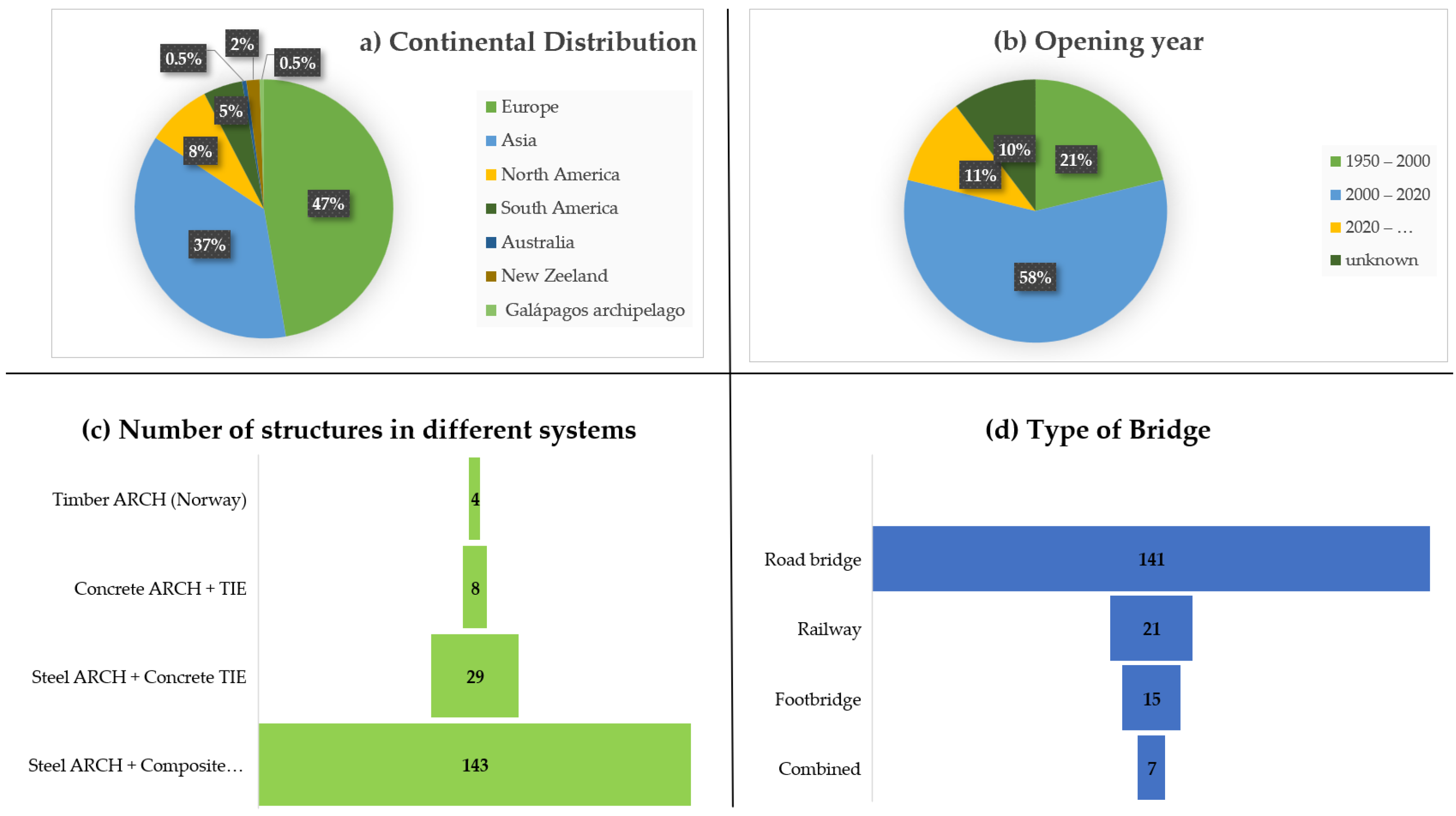
A total of 184 network arch bridge structures were identified using the map of the network arches [3], the Structurae database [7], literature references on NABs, and street views from Google Maps. While the total number of NABs is undoubtedly higher than those identified, we feel certain that most of the structures were found. In assessing whether a structure is an NAB or not, the definition stated at the beginning was taken into consideration, namely that “some of the hangers cross at least twice”.
From the point of view of continental distribution, Figure 17a, almost half of the world’s network arches are in Europe, with 47%, followed by Asia with 37% and North America with only 8%. The leading development of NABs in Europe is due to Prof. Tveit, who gave lectures on his idea for a bridge in more than 50 countries [2] and worked with students and colleagues from different universities in Europe to understand and improve the network arch bridge through several diploma, master’s and PhD theses [8,9,10,11,12,13,14,15]. As Prof. Tveit states in [1], Prof. Narouk saw a test model of the Fehmarn Sound Bridge in Hannover in 1960. He took the idea to Japan, where it flourished. Most of the NABs in Asia are located in Japan. The Japanese call these bridges Nielsen–Lohse bridges, but they are in fact network arches.
The distribution of the 184 structures according to the opening years is shown in Figure 17b. Most of the structures were opened to traffic between 2000 and 2020, more than twice as many as in the years the idea of a network arch was developed and started to be popularized. Without question, in the next 20 years, the NAB will show exponential growth as the idea spreads across the globe and engineers find improved solutions both in term of structural response and sustainable features [31,32,33,34,35,36] compared to other structural systems.
Figure 17c provides insight into the different structural systems used for NABs. Only 29 structures in the form proposed by Prof. Tveit have been built across the world. The vast majority are composite structures for the tie/deck. Such systems are chosen usually due to the simpler execution compared to the prestressed concrete deck. A very small number of arches were built in concrete, usually for architectural reasons, and four other bridges were built using wood as the arch material. All wooden arches are in Norway. The next chapter will have a subsection dedicated to research in glulam use for network arches.
Figure 17d shows the distribution of NABs for different purposes. Most network arches, a total number of 141, have been built as road bridges, 21 NABs are railway bridges, and seven structures are combined bridges for road, railway or road, railway, and pedestrian use. The seven structures designed as combined bridges are large spans, 177 m to 248 m in length, for bridges already used for traffic; larger spans of network arches, 280 m to 420 m in length, were identified for a bridge in China under construction at the time with three NAB spans [43,44]. The large spans of the combined NABs prove the reliability of the system for any type of load.
Of the identified structures, 15 are footbridges. The span range for pedestrian bridges varies from 40 m to 182 m. The largest pedestrian network arch is the George C. King Bridge in Calgary, Canada.
Twenty-one structures are railway NABs, with spans varying from 78 m, to the Torikai–Ohashi bridge in Osaka, Japan, under construction at the time, with five network arch spans of 85 + 130 + 195 + 130 + 85 m. In the category of railway NABs was a carbon hanger network arch, with a span of 127 m.
Of the 141 road structures, 10 were built to support one traffic lane; this category includes the slenderest NAB in the world, Brandanger Bridge, Figure 14; most of the structures, 97, were designed to support two or three traffic lanes, with or without pedestrian sidewalks; 32 were built to take four or five traffic lanes, and two of the structures ensure the crossing of more than six traffic lanes. The largest span network arch in the world, Bugrinsky Bridge, 380 m, was designed and built to support six road lanes, and Providence River Bridge in the United States of America carries 10 traffic lanes, five in each direction. Due to the large width of the bridge, 50 m, Providence River Bridge has three arch ribs instead of two. Extensive information on the design and construction of Providence River Bridge can be found in refs. [18,45].
The characteristics of the network arches built in timber are given in Table 1. WB is the notation used for wind bracings between the arches from this point forward.
Information regarding NABs built with the tie and the arch in concrete is given in Table 2. The presence of a bridge with the same name in Table 2, the Bijuli Bazar Bridge in Nepal, is no error, as two identical structures were identified in Kathmandu.
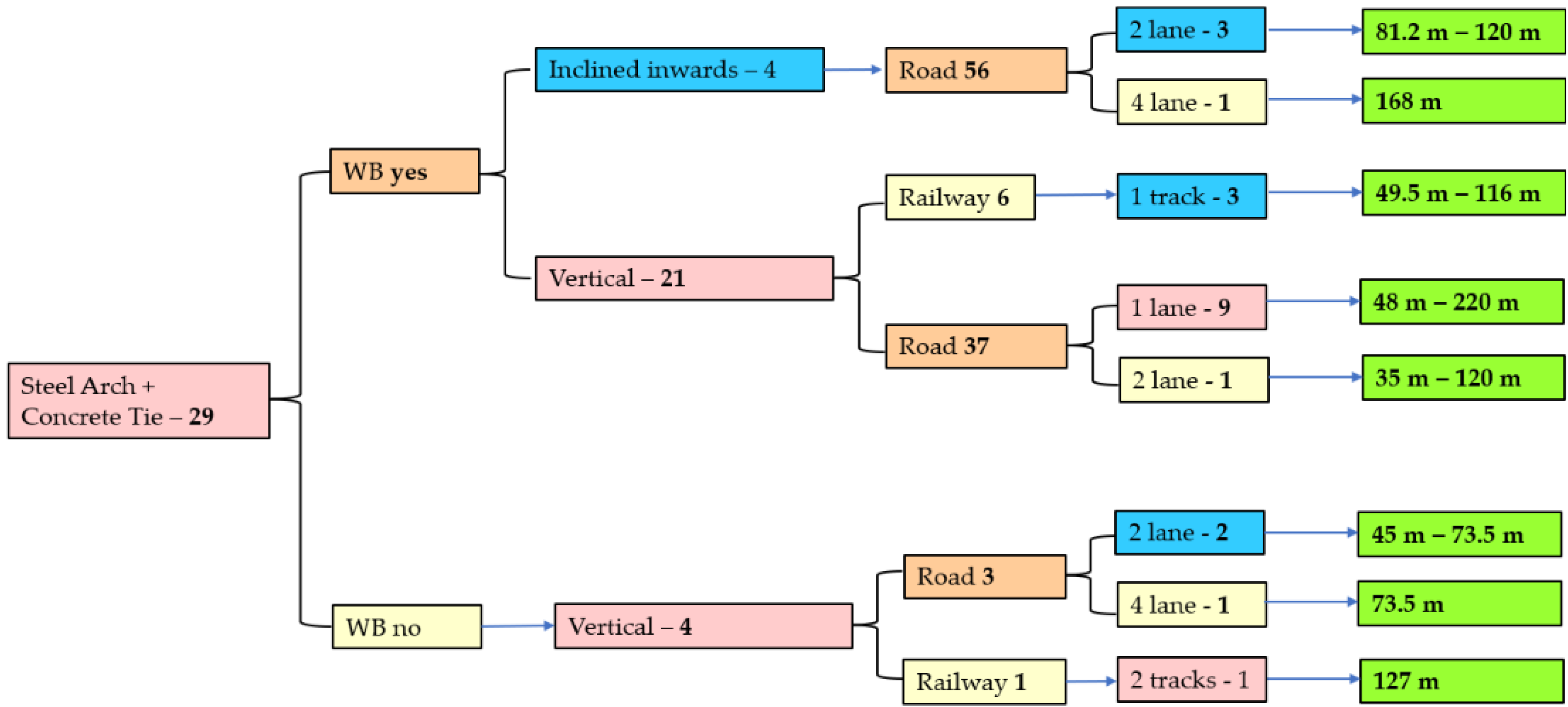
The network arches with no WB are shown in Figure 18. The network arches were classified as vertical arches, arches inclined inward, arches inclined outward, one arch splitting in two legs near the ends of the arch, and one central arch. For all of the structures taken into consideration here, no upper WBs are presented. The purpose of the bridge, the number of lanes, the structural system used, and the span range in meters are given. The largest span in this category is 200.4 m, the Troja Bridge in Prague, Figure 11, already mentioned in Section 3.3. In Figure 18, Figure 19, Figure 20, Figure 21 and Figure 22, the range span of each bridge structure is shown in green. The numbers presented in the other cells of Figure 18, Figure 19, Figure 20, Figure 21 and Figure 22 represent the number of network arches with that particular feature.
The pedestrian NABs are detailed in Figure 19.
Most of the network arches built, 142 structures identified worldwide, have the arch made of steel; in most cases, the cross-section is a tubular or box design, and the tie is made of steel or a composite steel/concrete section. Figure 20 and Figure 21 provide a classification according to the presence or absence of WB, position of the arches in the vertical plane, type of bridge (railway, road, combined or pedestrian), number of lanes and span range. A similar approach is used to present the 30 structures built using the “classical NAB” solution proposed by Prof. Tveit, with the arches made of steel and the ties in concrete, Figure 22.
In the case of steel arches with a composite deck, in the absence of WB, the span range is smaller, from 46 m to 162 m. For the same structural system, in the presence of WB, with the arches vertical, the span range varies from 30 m to 260 m, an increase of 65% of the span covered. With the inclination of the arches inward, the span varies from 44 m to 420 m, which translates into an increase of 250% compared to the case with no WB, and of 156% compared to the case of vertical arches with WB.
The case of a steel arch with a concrete deck, presented in Figure 22-, shows a span range varying from 35 m to 220 m for the slenderest NAB in the world, the Brandanger Bridge, with the remark that such a slender structure was possible due to the low traffic load, as the bridge was designed for one lane, with a deck of only 5 m.

4. Research on Network Arch Bridges

4.1. Network Arch Bridges in Timber

The first network arch in timber, Steien Bridge in Norway, was opened to traffic in 2016 [46,47], and to this day, it is the longest NAB with glulam arches, with a span of 88.2 m. The other network arches in timber are also in Norway; two of the bridges are road bridges with spans of 70 m and 34 m, and one a footbridge with a 52 m span. Even though Steien Bridge was the first timber NAB to be built, researchers’ interest into the use of glulam for network arches started years before. At the 8th International Conference on Timber Engineering, TCTE, held in Lahti, Finland, in 2004, Bell and Wolleback presented two papers [46,47] investigating an analysis of a network arch bridge with glulam arches with a span of 80 m. The conclusion in [46] was that if the overall stability of the system could be proven, the design could be viable. The deck solution adopted was presented in [47], having as its starting point the deck of a timber bridge already built. In ref. [47], a 3D model was investigated with respect to the in-plane and out-of-plane buckling analysis. The similarities and differences between the 2D analysis [46] and the 3D analysis were presented, and the overall conclusion was that the suggested design had sufficient stability properties [47].
In 2012, a master’s thesis was presented at Lund University investigating glulam arches [48]. The study had some limitations, but it proved again the possibility of using timber as the material of choice for the arch.
One year later, in 2013, at the International Conference on Timber Bridges held in Las Vegas, Nevada, USA, the first network arch built with timber arches was presented [42], and Malo and Ostrycharczyk presented the first of a series of papers investigating glulam NABs. In ref. [49], a scaled laboratory model of a bridge was presented, together with measured and numerically obtained vibrational modes, in the vertical and horizontal directions, of the timber deck. Ostrycharczyk, under the supervision of Prof. Malo, continued her studies and received her PhD from the Norwegian University of Science and Technology in 2017. In her doctoral thesis, Ostrycharczyk studied the case of an NAB with a light timber deck in transverse crossbeams [50] and introduced new hanger arrangements suitable for this type of bridge: the modified radial pattern and the “spoked wheel configuration of hangers”. In the spoked configuration, there are two sets of inclined hangers that have a coinciding point of fastening on the arch, while their fastening point on the deck is in the same longitudinal plane but in different points on the crossbeam; that leads to the hangers being inclined in and out of the plane of the arch. She also made a scaled model of one of the proposed configurations that was tested and used to calibrate numerical models. The results of the study [49] were published in a series of papers [51,52,53,54]. In ref. [55], the steps taken to choose the actual configuration of a network arch timber footbridge were presented, starting with the hanger configuration evaluated in the first step to other aspects involving the bridge design and erection. The case shown was the Vala Footbridge in Norway, with a span of 52.5 m, a width of 5.9 m and an arch rise of 8.4 m.
Another group compared a glulam arch they developed with a similar steel arch to determine the environmental benefits of timber arches using life-cycle assessment [56]. With the only modification in the bridge being the arch, the timber arch had a reduction of CO2 emissions of 20% compared to a similar steel arch.
The most recent study published on timber NABs is a master’s thesis from Sweden [57] assessing the performance of timber arch footbridges with different hanger configurations.

4.2. Network Arch Footbridge

As stated in Section 3.11, to date, 15 of the NABs around the world were built to support pedestrian and cyclist traffic. Except for the N-II Footbridge [58] in Madrid, Spain, that was opened to traffic in 2007, all other pedestrian structures were opened to traffic after 2010.
Extensive research into pedestrian NABs was conducted by Belevicius et al. [59,60,61,62]. The scope of their research was to find the optimal construction scheme for pedestrian radial network arch bridges with moderate spans of 30, 45, 60, 75 and 90 m [62]. The optimal scheme for the NAB was found by seeking the minimum mass of the whole bridge. Their findings for pedestrian structures were different than the recommendations for road and railway bridges: the rise-to-span ratio is set in the interval 0.2–0.3, the number of hangers should be higher than 40 even for short spans, and the optimal range of spread angles is 30° to 40° between the hangers. From a mathematical perspective, they employed a stochastic evolutionary algorithm to solve the global optimization problem formulated. In ref. [61], 220 optimal parameter sets for steel radial network arch footbridges were given. For each set, the arch rise, number of hangers, the spread angle of the hangers and the dimensions of the arch, tie and hangers were provided. In ref. [63], another optimization approach based on a genetic algorithm was proposed to find the hanger arrangement.
Besides the studies conducted by Belevicius, studies [54,57] dealing with the use of NABs as footbridges were already mentioned in Section 4.1.

4.3. Stability Analysis

The first to address the critical in-plane buckling load of network arches was Schanack in ref. [64], for the case with no hanger relaxation. He derived a formula for assessing the critical elastic in-plane buckling load on network arches, with the load over the entire span of the bridge. The design formula derived was verified in some network arches already built, and the variation compared to the finite element analysis was smaller than 5%.
The out-of-plane behavior of network arch bridges was addressed in ref. [65] as part of a method to assess the elastic buckling design of NABs. The proposed method was developed for arches with K-shaped bracings. The paper develops a set of formulas to assess the critical buckling force. The proposed formulation has a maximum error of 10% with respect to several refined FE results, in comparison to the simplified formulation in EC3 that shows large overestimation of the instability strength (up to 70% error compared to finite element analysis).
Another group studied the post-buckling of NABs subjected to vertical loads [66]. Their study was conducted for a 100 m long bridge with a width of 10 m, a rise-to-span ratio of 0.2, and the shape of the arch a parabola. The study included three analyses: a linear elastic buckling analysis, followed by a nonlinear analysis considering the geometrical nonlinearity and, finally, a pushover analysis with the purpose of evaluating the global out-of-plane capacity of the arch. The behavior of the arch was considered under traffic loads, without seismic force. Also, the study included a scenario with cable loss. The dynamic behavior of the arch observed was similar for one or two broken cables; the main difference in the case of two broken cables was in the amplitude of the out-of-plane displacement of the arch. The dynamic response of the arch was influenced by the position of the broken cable. Such a scenario near the abutments increases the dynamic sensitivity of the arch. On the other hand, a cable loss near the center of the arch can reduce the lateral buckling capacity by up to 25% in the case of slender arch cross-sections. Another group of authors investigated the behavior of NABs subjected to cable loss under moving loads [67,68]. The method chosen was a simplified static analysis of the 2D structure without the broken cable, subjected to dead and live loads, followed by two static forces that reproduced the dynamic effect of the sudden loss. For the bridge studied, the maximum displacement of the tie in the case of sudden cable loss was found to be near the sides of the bridge, at 2/5×L and 3/4×L, where L is the span of the bridge.
The most recent research into the nonlinear buckling analysis of NABs was conducted by Blonka et al. [69]. They compared the critical buckling factor using a linear and nonlinear buckling analysis. Nonlinear buckling analysis takes into account the nonlinear behavior of the cables. As their requirement was to find the limit point, third-order theory analysis was chosen, providing more accurate results for a slender structure in the case of large deflection, such as in the case of cables. The study was conducted for the bridge over the Vistula River in Cracow, and the vertical live load was a train load model from Eurocode, LM71. One interesting conclusion of their study, that is worth investigating in the future, is that additional tension in the hangers, above the forces resulting from self-tensioning, decrease the value of the critical load factor.

4.4. Hanger Arrangement

The hanger arrangement of a network arch bridge is the oldest research topic for such structures, but as spans, rise-to-span ratios, materials used and bridge cross-sections are diverging from the ideas of Tveit et al. [1,2,3,4,5,6,7,8,9,10,11,12,13,14,15,16,17,18], the issue of hanger arrangement appears in a series of other studies [50,51,52,53,54,57]. Papers published on the hanger arrangement and not mentioned so far include [70], where Brunn and Schanack make a summary of their doctoral studies, showing the advantages and disadvantages of five proposed hanger arrangements in terms of both structural response and user-friendliness. In ref. [71], another group presented a comparison for a concrete-filled steel tubular arch between the classical vertical disposition of the hangers: the fan arrangement and the network arrangement with parallel inclined hangers. A comparison between a 90 m tied-arch bridge with vertical hangers, three different Nielsen configurations of the hangers, and the network hanger configuration for parallel hangers with a slope angle 50–70° is given in ref. [72]. The case of a 100 m tied-arch bridge inclined inward by 15° is given in [73], where a comparison is made between an arch with vertical hangers varying in number from 5 to 50 and a network arrangement with parallel inclined hangers. The skew angle of the hangers was set to 40°, and the number of hangers varied from 40 to 85. The research presented was part of a doctoral thesis [74], and the configuration studied was used as the configuration of a road bridge opened to traffic in 2022, the Bridge at Ulmeni across the Somes River, in Romania. In ref. [75], a comparison between different hanger arrangements for a proposed road bridge with a span of 80 m with circular hollow cross-sections is given. The configurations studied were for 20, 22 and 24 hangers with a constant angle increase of 1.5° and a radial arrangement for 20, 22 and 24 hangers with an angle of 38° between the hanger and the radius. Another study [76] showed that a parabolic arch with two sets of radial hangers had good behavior in terms of resistance for a small rise-to-span ratio, compared to elliptical arches that showed poor performance in both strength and serviceability.
In any bridge design, a great deal of time is spent in finding the optimal configuration given the required span and other constraints. Two different groups of researchers worked to find optimization models for NABs. In ref. [77], an optimization model based on a three-step algorithm is given, with the remark that the procedure used does not ensure, a priori, a global optimum. In ref. [78], another optimized design using a global optimization algorithm (EVOP) was presented. EVOP was interfaced with Ansys to evaluate the structural response of the bridge. It was observed that a reduction of 38–40% in the total cost could be achieved for both circular and parabolic arches in the case of optimized design.

4.5. Other Research on Network Arch Bridges

Asymmetric NABs were studied in ref. [79], where the asymmetry was defined as an arch not symmetric to its center plane. A 100 m long asymmetric road arch bridge with a concrete tie/deck was chosen for the study. The principal difference seen was in the value of the compressive force, smaller on the steep side of the arch and larger where the shape of the arch was less curved. Even in the case of asymmetric arches, the overall behavior of an NAB in terms of bending moment distribution remains unchanged.
An interesting idea proposed by Valenzuela and Casas [80] was to use network arches to strengthen existing old beam bridges on multiple spans, where the piers are affected by scour and erosion. By changing the structural system, the intermediate infrastructures were eliminated; therefore, the erosion of piers is no longer a problem. The paper describes the steps needed to modify the superstructure and the design criteria.
A series of papers described the construction of German network arch bridges [81,82]. In ref. [81], the experience with the construction of a series of railroad NABs across Germany is presented: Rosenbachtal Bridge, opened in 2008, is an 89 m arch bridge that carries one railway track and has a hanger net of 36 flat steel hangers; Oder River Bridge, also known as the Frankfurt Railroad Bridge, also opened in 2008, has a span of 104 m, carries two railway tracks, and was designed with 26 flat steel hangers; the B6 Railroad Overpass, opened in 2009, has a span of 79 m, carries one railway track and has 24 flat hangers on each arch; Flora Bridge, opened in 2010, is a network arch with a span of 132.60 m and 30 flat steel hangers that carries one railway track. Brieselang Bridge is a highway network arch bridge completed in 2011, with a span of 106 m and a radial arrangement of the hangers. Brieslang Bridge comprises two independent NABs, one for each motorway direction. In ref. [82], aspects regarding the design and construction work are presented.
In refs. [83,84,85], a series of network arch road overpasses in Poland are presented, with the arch ribs made of hot-rolled profiles and the deck a longitudinally prestressed concrete slab. The four overpasses have spans varying from 62 m to 75 m and were opened to traffic in 2008 and 2009. Based on the experience gained at that time, a new overpass with a span of 120 m was constructed over the Lyna River, with the arches made of HD 400 × 744 and HD 400 × 1086 hot rolled profiles in steel grade S460 [85]. In 2018, a railroad NAB with a span of 116 m was erected in Krakow, using as the arch cross-section HD 400 × 1299 profiles.
The two network arches that are part of the Vienna Central Railway Station Bridge, both supporting a double-track railway with spans of 88.5 m and 112.5 m, are presented in [86,87]. Structural considerations, the form of the arch and the hanger arrangement, together with the bending moment and axial force diagrams, are given in ref. [86], and details from the builder in relation to the construction method used are given in ref. [87].
River Irwell Crossing, the first NAB built in the United Kingdom, is introduced in [88]. The bridge was designed with a weathering steel box section, the arch axis is circular, and the plate thickness of the cross-section varies from 40 mm to 60 mm. The form of the bridge was dictated by esthetic requirements; the arch on the main span has an apparent continuation of the approach span. The technical report [88] gives insight into all stages of the bridge’s construction, from the overall concept to the stressing of the hangers.
In another technical report [89], the international award-winning design of the Perry Bridge Network Arch over the Waikato River in New Zeeland is presented. Perry Bridge spans 130 m with two inclined steel tube arches that are braced together. The rise of the bridge is 18 m, thus leading to a rise-to-arch ratio of 0.138, while most NAB designs are in the range 0.15 to 0.20, even higher in the case of timber arches. The hanger arrangement is particular to this structure, as the hanger angles were varied to provide some of the benefits of the radial arrangement but maintaining regular connection along the deck. The bridge has been nominated for many awards, the most notable being the Structural Awards 2018, by the Institution of Structural Engineers in London, where it won the award for excellence in the design of pedestrian and/or cycle bridges.

5. Conclusions

This paper provides a review of the literature published on network arch bridges and provides insight into the evolution of the network arch from the middle of the last century to the present day. An extensive review of the literature on the subject was presented.
The purpose of this paper was to answer whether the NAB is a suitable structure for all ranges of spans, from small to very large ones, and whether it could have a beneficial impact in the construction industry from an environmental perspective. The main conclusions of this study can be formulated as follows:
  • The network arches had spans varying from 30 m up to 380 m for bridges already built and 420 m for a bridge under construction at the time; the already-built structures prove the reliability of network arches for spans varying from small to very large ones.
  • The discussion at this point could be whether the NAB is still a good idea for very small spans. No published research was found to compare the overall cost of the NAB to another type of structure in terms of materials and overall price of the bridge for spans smaller than 100 m; however, the experience of the authors with a 36 m NAB built in Romania, the Unirii Bridge at Maieru, is that it was less costly than a competing alternative.
  • Numerous published papers show a reduction in the materials used for 100 m network arches compared to arches with vertical hangers; other research published and structures already open to traffic prove the possibility of using sustainable materials for the arches or the hangers, such as timber of carbon fiber reinforced plastic. Both arguments demonstrate the potential the structural system has to align the bridge industry with the policy of net-zero CO2 emissions by 2050, at least in part.
  • Some of the structures mentioned throughout the paper, including the Sixth Street Viaduct in Los Angeles, the Perry Bridge in New Zeeland or the River Irwell Crossing in the United Kingdom showcase the possibility of combining esthetic requirements with structural efficiency.
The limitations of this review include the fact that no insight into the technological challenges of erecting a network arch bridge were given. The authors feel that many details on the technology have been given in the papers published by Prof. Tveit and papers presenting different structures. We decided not to include this aspect in the present review.
Future research directions can be explored when discussing the network arch. Looking at the Sixth Street Viaduct in Los Angeles, a network arch with the arches slightly inclined outward of the plane of symmetry, the bridge can be seen as an evolution of the structural form toward a butterfly arch bridge; further research into the behavior of such a structural system should be considered.
Stability analyses were performed for different structures, but an extension of the buckling design procedure from EC3 for arches with vertical hangers to network arches is needed.
Extended research into the behavior of small span NABs with a reduced number of hangers can be considered. The authors are already looking into it.
For pedestrian network arch bridges, one interesting finding worth investigating in the future is that the rise-to-span ratio should be larger, 0.2 to 0.3 instead of 0.15 to 0.2.
No definitive answer has been obtained yet as to whether a change in curvature at the springs of the arch can reduce the overall cost of the bridge or not.
Using third-order analysis, a group of researchers found that additional tension in the hangers, above the force from self-tensioning, decreases the value of the critical load factor. Such a finding is also worth investigating in the future.
As can be inferred from the points mentioned above, the research and development of the network arch is still ongoing. However, what we can say for certain is that in the 60 years since the first structure was opened to traffic, the idea of Prof. Tveit proved to be reliable for all span ranges, and the potential for further improvements and development is still there.

Author Contributions

Conceptualization, A.D.D.; methodology, A.D.D., Ș.I.G. and C.M.; investigation, A.D.D.; resources, M.C. and M.L.D.; writing—original draft preparation, A.D.D.; writing—review and editing, M.C.; visualization, V.M.; supervision, Ș.I.G.; project administration, A.D.D.; funding acquisition, M.L.D. All authors have read and agreed to the published version of the manuscript.

Funding

This research was funded by SC DIFERIT SRL, grant number 39029/24.11.2022, and the APC was funded by the Technical University of Cluj-Napoca.

Institutional Review Board Statement

Not applicable.

Informed Consent Statement

Not applicable.

Data Availability Statement

Not applicable.

Acknowledgments

The first author would like to express her gratitude to Per Tveit for the two encounters they had, the first in 2006 in Trondheim, and the second in 2019 in Grimstad, Norway. Tveit is a true inspiration for engineers working in the field of bridge engineering, and the ideas they exchanged led to this project.

Conflicts of Interest

The authors declare no conflict of interest. The funders had no role in the design of the study; in the collection, analyses, or interpretation of data; in the writing of the manuscript, or in the decision to publish the results.

References

  1. Tveit, P.; (Agder University, Grimstad, Norway). About the Network Arch. Personal communication, 2nd ed.. 2011. [Google Scholar]
  2. Tveit, P.; (Agder University, Grimstad, Norway). The Network Arch. Bits of Manuscipt in March 2014 after Lectures in 50+ Countries. Personal communication, 2014. [Google Scholar]
  3. Map of Network Arch Bridges. Available online: https://home.uia.no/pert/index.php/Map_of_Bridges (accessed on 24 August 2023).
  4. Nielsen, O.F. Foranderlige Systemer med Anvendelse på Buer Med Skraatstillede Hængestenger (Discontinuous Systems used on Arches with Inclined Hangers). Ph.D. Thesis, Gad Copenhagen, Copenhagen, Denmark, 1930. (In Danish). [Google Scholar]
  5. Tveit, P. How to design economical network arches. IOP Conf. Ser. Mater. Sci. Eng. 2019, 471, 052078. [Google Scholar] [CrossRef]
  6. Larsse, R.M.; Jakobsen, K.A. Brandangersundet Bru—Verdens slankeste? Nyh. Om Stalbyggnad 2006, 3, 37–40. (In German) [Google Scholar]
  7. Structurae dabatase on the Network Arch Bridge. Available online: https://structurae.net/en/ (accessed on 27 September 2023).
  8. Teich, S.; Wendelin, S. Vergleichsrechnung einer Netzwerkbogenbrückeunter Einsatz des Europäischen Normenkonzeptes. Ph.D. Thesis, Technische Universitat Dresden, Dresden, Germany, 2001. (In German). [Google Scholar]
  9. Steinmann, U. Berechnung und Konstruktion einer stahlernen Eisenbahn-Stabbogenbrucke mit Netzwerkhangern. Ph.D. Thesis, Technische Universitat Dresden, Dresden, Germany, 2002. (In German). [Google Scholar]
  10. Brunn, B.; Schanack, F. Calculation of a Double Track Railway Network Arch Bridge Applying the European Standards. Master’s Thesis, Dresden University of Technology, Dresden, Germany, 2003. [Google Scholar]
  11. Teich, S. Beitrag zur Optimierung von Netzwerkbogenbrucken. Contribution to Optimizing Network Arch Bridges. Ph.D. Thesis, Dresden University of Technology, Dresden, Germany, 2012. (In German). [Google Scholar]
  12. Rack, M. Entwurf Einer Kombinierten Strassen-Eisenbahn-Netzwerkbogenbrucke. Master’s Thesis, TU-Dresden, Dresden, Germany, 2003. (In German). [Google Scholar]
  13. Niklison, A.J. Statical Analysis of Network Arch Bridges. Master’s Thesis, Universität Stuttgart, Stuttgart, Germany, 2010. [Google Scholar]
  14. Varennes, M. Design of a Single-Track Railway Network Arch Bridge. Master’s Thesis, School of Engineering Sciences (SCI), Stockholm, Sweden, 2011. [Google Scholar]
  15. Da Costa, B.N. Design and Analysis of a Network Arch Bridge. Master’s Thesis, Tecnico Lisboa, Lisbon, Portugal, 2013. [Google Scholar]
  16. Tveit, P. Systematic Thesis on Network Arches, Agder University, Grimstad, Norway. Personal Communication. 2014. Available online: http://home.uia.no/pert (accessed on 21 July 2023).
  17. Tveit, P. Graduation Thesis on Arch Bridges with Inclined Hangers. Master’s Thesis, Technical University of Norway, Trondheim, Norway, 1955. [Google Scholar]
  18. Tveit, P. Arch Bridges with Inclined Intersecting Hangers. Ph.D. Thesis, Technical University of Norway, Trondheim, Norway, 1959. (In Norwegian). [Google Scholar]
  19. Yousefpour, H.; Helwig, T.A.; Bayrak, O. Construction stresses in the world’s first precast concrete network arch bridge. PCI J. 2015, 60, 30–47. [Google Scholar] [CrossRef]
  20. Yousefpour, H.; Gallardo, J.M.; Helwig, T.A.; Bayrak, O. Innovative precast, prestressed concrete network arches: Elastic response during construction. Struct. Concr. 2017, 18, 768–780. [Google Scholar] [CrossRef]
  21. Janata, V.; Gregor, D.; Sasek, L.; Nehasil, P.; Wangler, T. New Troja Bridge in Prague—Structural Solution of Steel Parts. Procedia Eng. 2012, 40, 159–164. [Google Scholar] [CrossRef]
  22. Tveit, P. Construction of the Troja Bridge in Prague. Personal Communication. Available online: https://home.uia.no/pert/data/Troja_bridge.pdf (accessed on 13 June 2023).
  23. Gregor, D.; Janata, V.; Sasek, L.; Nehasil, P.; Broz, R. New Troja Bridge—Concept and Structural Analysis of Steel Parts. Procedia Eng. 2012, 40, 131–136. [Google Scholar] [CrossRef]
  24. Larssen, R.M.; Jakobsen, S.E. Brandangersundet Bridge—A Slender and Light Network Arch. In Proceedings of the 35th Annual Symposium of IABSE/52nd Annual Symposium of IASS/6th International Conference on Space Structures: Taller, Longer, Lighter-Meeting Growing Demand with Limited Resources, London, UK, 20–23 September 2011. [Google Scholar]
  25. Ronnquist, A.; Naess, A. System reliability analysis of slender Network Arch Bridges. In Proceedings of the Computational Methods in Structural Dynamics and Earthquake Engineering, Kos Island, Greece, 12–14 June 2013. [Google Scholar]
  26. Ronnquist, A.; Naess, A. Global Buckling Reliability Analysis of Slender Network Arch Bridges: An Application of Monte Carlo-Based Estimation by Optimized Fitting. In Risk and Reliability Analysis: Theory and Applications; Gardoni, P., Ed.; Springer Series in Reliability Engineering; Springer: Cham, Switzerland, 2017. [Google Scholar] [CrossRef]
  27. Millanes, F.M.; Ortega, M.; Carnerero, A. Palma del Rio Arch Bridge, Cordoba, Spain. Struct. Eng. Int. 2010, 3, 338–342. [Google Scholar] [CrossRef]
  28. Millanes, F.; Ortega, M.; Carnerero, A. Project of two metal arch bridges with tubular elements and network suspension system, steel bridges: Advanced solutions & technologies. In Proceedings of the 7th International Conference on Steel Bridges Proceedings, Guimaraes, Portugal, 4–6 June 2008. [Google Scholar]
  29. Mato, F.M.; Cornejo, M.O.; Agromayor, D.M.; Perez, P.S. The use and development of the Network Suspension System for Steel Bowstring Arches. In Proceedings of the 7th Congresso de Construçao Metálica e Mista/Cmm-Associaçao (Portuguesa de Construçao Metálica e Mista), Lisbon, Portugal, 4–6 June 2008. [Google Scholar]
  30. Mato, F.M.; Cornejo, M.O.; Sanchez, J.N. Design and Construction of Composite Tubular Arches with Network Suspension System: Recent Undertakings and Trends. J. Civ. Eng. Archit. 2011, 5, 191–214. [Google Scholar]
  31. World’s First Network Arch Bridge with CFRP Hangers. Available online: https://www.compositesworld.com/news/german-railway-bridge-suspended-on-cfrp-hangers (accessed on 27 July 2023).
  32. Haspel, L. Bauen mit Zuggliedern aus Carbon. In Proceedings of the 14. Fachtagung Baustatik—Baupraxis, Stuttgart, Germany, 8–9 May 2021. [Google Scholar]
  33. Haspel, L. Netzwerkbogenbrücken mit Hängern aus Carbon. Stahlbau 2019, 8, 153–159. [Google Scholar] [CrossRef]
  34. Keil, A.; Haspel, L. Stadtbahnbrucke—Built innovation: An integral supported network arch with CFRP hangers. Bautech 2021, 98, 149–158. [Google Scholar] [CrossRef]
  35. Haspel, L. Carbon network arch—Lessons from the first use of carbon network cables. Stahlbau 2022, 91, 84–94. [Google Scholar] [CrossRef]
  36. Meier, U.O.; Winistorfer, A.U.; Haspel, A. World’s first large bridge fully relying on carbon fiber reinforced polymer hangers. In Proceedings of the SAMPE Conference, The Future Composite Footprint, Amsterdam, The Netherlands, 30 September–1 October 2020. [Google Scholar]
  37. German Civil Engineer Award. 2022. Available online: https://www.sbp.de/en/news/stadtbahnbruecke-in-stuttgart-erhaelt-deutschen-ingenieurbaupreis-2022 (accessed on 27 July 2023).
  38. Bojovic, A.; Mora Munoz, A.; Markovic, Z.; Aleksic, D.; Pavlovic, M.; Spremic, A. Railway Road Bridge in Novi Sad—Design and Erection. In Proceedings of the 37th IABSE Symposium, Madrid, Spain, 3–5 September 2014. [Google Scholar] [CrossRef]
  39. Bojovic, A.; Mora Markovic, Z.; Pavlovic, M.; Novakovic, N.; Spremic, M. Railway Road Bridge in Novi Sad. Steel Tied network arches across the Danube. IOP Conf. Ser. Mater. Sci. Eng. 2018, 419, 0120032. [Google Scholar] [CrossRef]
  40. SHM System of the Zezelj (Novi Sad) Bridge. Available online: https://www.hbkworld.com/en/knowledge/resource-center/case-studies/2023/bridge-monitoring-an-example-from-hbm#!ref_www.hbm.com (accessed on 28 July 2023).
  41. Veie, J.; Bjertnaes, M.; Stensby, T.A. New dimensions in bridge construction in Norway. In Proceedings of the Internationales Holzbau-Forum IHF, Innsbruck, Norway, 2–4 December 2015. [Google Scholar]
  42. Veie, J.; Abrahamsen, R.B. Steien Network Arch. In Proceedings of the International Conference on Timber Bridges, Las Vegas, NV, USA, 30 September–2 October 2013. [Google Scholar]
  43. Zhou, W.; Chen, L.; Shao, C.; Wu, X. A Long-span Network Arch Birdge for Road and Rail Traffic. Struct. Eng. Int. 2022, 32, 211–215. [Google Scholar] [CrossRef]
  44. Lai, Y.; Li, Y.; Huang, M.; Zhao, L.; Chen, J.; Min Xie, Y. Conceptual design of long span steel-UHPC composite network arch bridge. Eng. Struct. 2023, 277, 115–434. [Google Scholar] [CrossRef]
  45. Steere, P.; Wu, Y. Design and construction of the Providence River Bridge. In Proceedings of the 25th Annual International Bridge Conference Engineers’ Society of Western Pennsylvania, Pittsburgh, PA, USA, 2–4 June 2008. [Google Scholar]
  46. Bell, K.; Wollebaek, L. Large, mechanically joined glulam arches. In Proceedings of the 8th World Conference on Timber Engineering WCTE 2004, Lahti, Finland, 14–17 June 2004. [Google Scholar]
  47. Wollebaek, L.; Bell, K. Stability of glulam arches. In Proceedings of the 8th World Conference on Timber Engineering WCTE 2004, Lahti, Finland, 14–17 June 2004. [Google Scholar]
  48. Nylander, E. A feasibility Study of a Network Arch Bridge with Glulam Arches. Master’s Thesis, Lund University, Lund, Sweden, 2012. [Google Scholar]
  49. Malo, K.S.; Ostrycharczyk, A.; Barli, R.; Hakvag, I. On development of network arch bridges in timber. In Proceedings of the International Conference on Timber Bridges, Las Vegas, NV, USA, 30 September 2013. [Google Scholar]
  50. Ostrycharczyk, A.V. Network arch timber bridges with light timber deck on transverse crossbeams. Ph.D. Thesis, Norwegian University of Science and Technology, Trondheim, Norwegian, 2017. [Google Scholar]
  51. Ostrycharczyk, A.V.; Malo, K.A. Comparison of network patterns suitable for timber bridges with crossbeams. In Proceedings of the ICTB, 3rd International Conference on Timber Bridges, Skelleftea, Sweden, 26–29 June 2017. [Google Scholar]
  52. Ostrycharczyk, A.V.; Malo, K.A. Parametric study of radial hanger patterns for network arch timber bridges with a light deck on transverse crossbeams. Eng. Struct. 2017, 153, 491–502. [Google Scholar] [CrossRef]
  53. Ostrycharczyk, A.V.; Malo, K.A. Parametric study on effects of load position on the stress distribution in network arch timber bridges with light timber decks on transverse crossbeams. Eng. Struct. 2018, 163, 112–121. [Google Scholar] [CrossRef]
  54. Ostrycharczyk, A.V.; Malo, K.A. Network arch timber bridges with light timber decks and spoked configuration of hangers—Parametric study. Eng. Struct. 2022, 253, 113–782. [Google Scholar] [CrossRef]
  55. Ostrycharczyk, A.V.; Vaernes, A. Vala bridge—Timber network arch footbridge in Ringebu, Norway. In Proceedings of the 4th International Conference on Timber Bridges ICTB 2021 Plus, Biel/Bienne, Switzerland, 9–12 May 2021. [Google Scholar]
  56. O’Born, R.; Vertes, K.; Pytten, G.; Hortemo, L.O.; Braendhagen, A. Life cycle assessment of an optimized network arch highway bridge utilizing timber. In Proceedings of the 10th Conference on the Bearing Capacity of Roads, Railways and Airfields, Athens, Greece, 28–30 June 2017. [Google Scholar]
  57. Garcia, A.G. A parametric Study of the Static and Dynamic Performance of Timber Arch Footbridges with Different Hanger Configurations. Master’s Thesis, KTH Royal Institute of Technology, Stockholm, Sweden, 2022. [Google Scholar]
  58. Mato, F.M.; Rubio, L.M.; Sanchez, J.N. Bowstring footbridges in the cycling ring road in Madrid. In Proceedings of the 3rd International Conference on Footbridges: Footbridge 2008—Footbridges for Urban Renewal, Porto, Portugal, 2–4 July 2008; pp. 133–134. [Google Scholar]
  59. Belevicius, R.; Juozapaitis, A.; Rusakevicius, D. Parameter Study on Weight Minimization of Network Arch Bridges. Period. Polytech. Civ. Eng. 2018, 62, 48–55. [Google Scholar] [CrossRef]
  60. Belevicius, R.; Juozapaitis, A.; Rusakevicius, D.; Zilenaite, S. Parametric study on mass minimization of radial network arch pedestrian bridges. Eng. Struct. 2021, 237, 112–182. [Google Scholar] [CrossRef]
  61. Belevicius, R.; Juozapaitis, A.; Rusakevicius, D.; Zilenaite, S. Optimal schemes of radial network arch pedestrian bridge: An extensive dataset of solutions under different conditions. Data Brief 2021, 36, 107–149. [Google Scholar] [CrossRef]
  62. Belevicius, R.; Rusakevicius, D.; Valentinavicius, S. Insights into Optimal Schemes of Radial Network Arch Pedestrian Bridge. Adv. Civ. Eng. 2022, 36, 6951775. [Google Scholar] [CrossRef]
  63. Tan, Y.G.; Yao, Y.B. Optimisation of hanger arrangement in pedestrian tied arch bridge with sparse hanger system. Adv. Struct. Eng. 2019, 22, 2594–2604. [Google Scholar] [CrossRef]
  64. Schanack, F. Calculation of the critical in-plane buckling load of network arches. Bautech 2009, 86, 249–255. [Google Scholar] [CrossRef]
  65. Lonetti, P.; Pascuzzo, A. A practical method for the Elastic Buckling Design of Network Arch Bridges. Int. J. Steel Struct. 2020, 20, 311–329. [Google Scholar] [CrossRef]
  66. Zampieri, P.; Tetougueni, C.D.; Maiorana, E.; Pellegrino, C. Post-buckling of network arch bridges subjected to vertical loads. Struct. Infrastruct. Eng. 2021, 17, 941–959. [Google Scholar] [CrossRef]
  67. Bruno, D.; Lonetti, P.; Pascuzzo, A. A numerical study on network arch bridges subjected to cable loss. Int. J. Bridge Eng. 2018, 6, 41–59. [Google Scholar]
  68. Ammendolea, D.; Bruno, D.; Greco, F.; Lonetti, P.; Pascuzzo, A. An investigation on the structural integrity of network arch bridges subjected to cable loss under the action of moving loads. Procedia Struct. Integr. 2020, 25, 305–315. [Google Scholar] [CrossRef]
  69. Blonka, A.; Skretkowicz, L. Nonlinear buckling analysis of network arch bridges. Stud. Geotech. Et Mech. 2022, 44, 123–137. [Google Scholar] [CrossRef]
  70. Schanack, F.; Brunn, B. Generation of network arch hanger arrangement. Stahlbau 2009, 78, 443–522. [Google Scholar] [CrossRef]
  71. An, L.H.; Duy, D.M. Research on the hanger arrangement for the concrete filled steel tubular arch bridge with rod and roadway located under arch rib: Sustainable arch bridges. In Proceedings of the 3rd Chinese-Croatian Joint colloquium on Sustainable Arch Bridges, Zagreb, Croatia, 15–16 July 2011. [Google Scholar]
  72. Danciu, A.D.; Gutiu, S.I.; Moga, C. Bi-dimensional analysis of a 90 m arch with different hanger arrangements. In Proceedings of the Nano, Bio and Green—Technologies for a Sustainable Future Conference, Albena, Bulgaria, 16–22 August 2021; SGEM: Vienna, Austria, 2016; Volume 2, pp. 477–484. [Google Scholar]
  73. Vlad, M.; Kollo, G.; Marusceac, V. A modern approach to tied-arch bridge analysis and design. Acta Teh. Corviensis—Bull. Eng. 2015, 8, 33–37. [Google Scholar]
  74. Vlad, M. Study on Concept and Design of Cable Structures. Ph.D. Thesis, Technical University of Cluj-Napoca, Cluj, Romania, 2019. (In Romanian). [Google Scholar]
  75. Danciu, A.D.; Gutiu, S.I.; Moga, C.; Bucerzan, M. Comparative Analysis between the Hanger Arrangement in an 80 m Network Arch Bridge with Circular Hollow cross-sections. Lect. Notes Netw. Syst. 2022, 386, 110–119. [Google Scholar] [CrossRef]
  76. Bayyavarapu, R.; Talukdar, S.; Lalthlamuana, R. Effect of rise to span ratio on the Behavior of a Steel Arch Bridge for different types of Hanger Arrangement. Steel and Aluminium Structures. In Proceedings of the 8th International Conference on Steel and Aluminium Structures (ICSAS), Hong Kong, China, 7–9 December 2016. [Google Scholar]
  77. Bruno, D.; Lonetti, P.; Pascuzzo, A. An optimization model for the design of network arch bridges. Comput. Struct. 2016, 170, 13–25. [Google Scholar] [CrossRef]
  78. Islam, N.; Rana, S.; Ahsan, R.; Ghani, S.N. An Optimized Design of Network Arch Bridge Using Global Optimization Algorithm. Adv. Struct. Eng. 2016, 17, 197–210. [Google Scholar] [CrossRef]
  79. Zwingmann, B.; Schanack, F.; Marx, S. Asymmetric network arch bridges. Stahlbau 2009, 78, 471–476. [Google Scholar] [CrossRef]
  80. Valenzuela, M.A.; Casas, J.R. Bridge strengthening by conversion to network arch: Design criteria and economic validation. Struct. Infrastruct. Eng. 2016, 12, 1310–1322. [Google Scholar] [CrossRef]
  81. Gautier, P.; Krontal, L. Experiences with Network arches for railway bridges. Stahlbau 2010, 79, 199–208. [Google Scholar] [CrossRef]
  82. Degenhardt-Herberger, K.; Reinke, K.D. Reconstruction of the motorway bridge over the Havelkanal near Breselang, Germany. Stahlbau 2012, 81, 91-U4. [Google Scholar] [CrossRef]
  83. Rademacher, D.; Ochojski, W.; Lorenc, W.; Kozuch, M. Advanced solutions with hot-rolled sections for economical and durable bridges. Steel Constr. Des. Res. 2018, 11, 196–204. [Google Scholar] [CrossRef]
  84. Kaczmarek, T.; Galewski, T.; Topolewicz, K.; Sek, R.; Radziecki, A.; Ochojski, W.; Kozuch, M.; Lorenc, W. Polish experience with network arch bridges using cold-bent HD sections. Steel Constr. Des. Res. 2020, 13, 271–279. [Google Scholar] [CrossRef]
  85. Zanon, R.; Matos, R.; Rademacher, D.; Lorenc, W. Network arch bridges with rolled sections: Ideas for economic and durable detailing. In Proceedings of the 12th Conference on Steel and Composite Construction, Coimbra, Portugal, 21–22 November 2019; Ernst&Sons: Medford, MA, USA; pp. 106–116. [Google Scholar]
  86. Heinlein, M.; Einhauser, O. Network arch bridges for the OBB over the central marshalling yard at Vienna-Kledering, Austria—Structural and constructional design of the bridges. Stahlbau 2013, 82, 334–339. [Google Scholar] [CrossRef]
  87. Stelzer, B.; Dorrer, G. Two network arch bridges: Connection between the existing railway lines Ostbahn and Flughafenschnellbahn in Vienna, Autrisa—Characteristics form the point of view of steel constructors. Stahlbau 2013, 82, 326–333. [Google Scholar] [CrossRef]
  88. Rusev, R.; Foster, R.; Abbott, T.; Bistolas, A. River Irwell Crossing—UK’s First Network Arch Bridge. Struct. Eng. Int. 2019, 29, 309–314. [Google Scholar] [CrossRef]
  89. Brook, T.; Gaby, P. Perry Bridge Network Arch—Elegance in Efficiency. Struct. Eng. Int. 2020, 30, 250–253. [Google Scholar] [CrossRef]
Figure 1. Nielsen bridge: (a) Nielsen bridge at Castelmoron in France, 1933. Span of 145 m. (b) Design of a bridge with crossing hangers from a patent application in 1926.
Applsci 13 10966 g001
Figure 2. Data collection flow of the research.
Applsci 13 10966 g002
Figure 3. Reduced curvature of the arch near the supports.
Applsci 13 10966 g003
Figure 4. Universal column versus two box sections for a network arch with a span of 135 m. “Reprinted/adapted with permission from Ref. [1]. 2011, prof. Per Tveit”.
Applsci 13 10966 g004
Figure 5. Shape for the tie and deck “Reprinted/adapted with permission from Ref. [2]. 2014, prof. Per Tveit”.
Applsci 13 10966 g005
Figure 6. Necessary thickness of the slab vs. the span in the transverse direction.
Applsci 13 10966 g006
Figure 7. Hanger arrangement with equally spaced hangers along the arch, a start angle on the tie and the angle change along the tie.
Applsci 13 10966 g007
Figure 8. Radial hanger arrangement: (a) Construction of the radial arrangement; (b) radial hanger arrangement configuration.
Applsci 13 10966 g008
Figure 9. The network arch bridge at Steinkjer in Norway: street view of the bridge.
Applsci 13 10966 g009
Figure 10. Street view of the West Seven Street Bridge in Forth Worth, Texas, from Google street view.
Applsci 13 10966 g010
Figure 11. Street view of the Troja Bridge, Prague, Czech Republic, from Google Street view.
Applsci 13 10966 g011
Figure 12. The Sixth Street Viaduct in Los Angeles. Photo © Gary Leonard, 2022.
Applsci 13 10966 g012
Figure 13. The Brandanger Bridge in Norway: side view of the bridge.
Applsci 13 10966 g013
Figure 14. Hanger crossing device in the form of a needle eye; from Google Street view.
Applsci 13 10966 g014
Figure 15. Stuttgart Stadtbahn Bridge.
Applsci 13 10966 g015
Figure 16. The Steien Bridge: Side view of the bridge.
Applsci 13 10966 g016
Figure 17. NABs in numbers: (a) Continental distribution; (b) opening year; (c) number of structures in different systems; (d) types of bridges.
Applsci 13 10966 g017
Figure 18. Network arch bridges with no upper wind bracing. In bold are the number of structures of that type and the span range. The rest of the color code is taken as follows: road bridges in orange, railway in yellow, pedestrian bridges in green and combined bridges in blue; structures with a steel arch and composite tie in light red, structures with a concrete arch and a concrete tie in light blue, structures with a steel arch and a concrete tie in light yellow. In green is the span range for every type of bridge.
Applsci 13 10966 g018
Figure 19. Pedestrian network arch bridges. In bold are the number of structures of that type and the span range. The rest of the color code is taken as follows: bridges with a WB in orange, bridges without WB in light yellow; arches inclined inward in blue, one central arch in light blue and vertical arches in light red; structures with a steel arch and composite tie in light red, structures with a concrete arch and a concrete tie in light blue, composite tie in pink. In green is the span range for every type of bridge.
Applsci 13 10966 g019
Figure 20. Network arches with steel arches and steel ties/composite decks. In bold are the number of structures of that type and the span range. The rest of the color code is taken as follows: bridges with a WB in orange, bridges without WB in light yellow; arches inclined inward in blue, vertical arches in light red; road bridges in orange, railway in yellow, pedestrian bridges in green and combined bridges in blue; bridges with one railway track and road bridges with two traffic lanes in blue, railway bridges with 2 tracks and road bridges with 3 traffic lanes in light red and 4 lane road bridges in light yellow. In green is the span range for every type of bridge, and in yellow the figures continuing Figure 21.
Applsci 13 10966 g020
Figure 21. Network arches with steel arches and steel ties/composite decks. Continuation of Figure 19. In bold are the number of structures of that type and the span range. The rest of the color code is taken as follows: arches inclined inward in blue, vertical arches in light red; road bridges in orange, railway in yellow, pedestrian bridges in green and combined bridges in blue; railway bridges with 1 track in blue, with 2 tracks in light red; road bridges 1 lane in light red, 2 lanes in blue, 3 and 6 lanes in pink, 4 lanes in light yellow, 5 lanes in green and 10 lanes in orange. In green is the span range for every type of bridge.
Applsci 13 10966 g021
Figure 22. Network arches with steel arches and concrete ties. In bold are the number of structures of that type and the span range. The rest of the color code is taken as follows: arches inclined inward in blue, vertical arches in light red; road bridges in orange, railway in yellow; railway bridges with 1 track in blue, with 2 tracks in light red; road bridges 1 lane in light red, 2 lanes in blue, 4 lanes in light yellow. In green is the span range for every type of bridge.
Applsci 13 10966 g022
Table 1. Timber Network Arches.
Bridge NameLocationOpening YearTypeSpan [m]ArchTieLateral Buckling
Steien BridgeAlvdal, Norway2016Road88.2Glulam, truss boxConcreteArch inclined inward, WB
Våla BridgeRingube, Norway2020Pedestrian52Glulam, boxConcreteArch inclined inward, WB
HellefossbruaEtnedal, Norway2019Road70Glulam, boxConcreteArch inclined inward, WB
Prestmyra bruElverum, Norway2018Road34Glulam, boxConcreteWB
Table 2. Concrete Network Arch Bridges.
Bridge NameLocationOpening YearTypeTrafficSpan [m]Arch + TieArches + WB
Steflinger River BridgeSteflinger, Germany2015Road2 lane55ConcreteVertical, no WB
Nervión BridgeBilbao, Spain2017Railway2 tracks80ConcreteInclined inward, WB
Bijuli Bazar BridgeKathmandu, Nepal2019Road2 lane52ConcreteVertical, WB
Rayar Bazar BridgeDacca, Bangladesh2015PedestrianPedestrian40ConcreteVertical, WB
Tsukani BridgeMitsuqi Dam, JapanNARoad2 lane151ConcreteVertical, WB
W 7th Street BridgeDallas, USA2013Road2 lane6 × 50ConcreteVertical, WB
Bent BridgeSan Josa, USA2011PedestrianPedestrian82.3ConcreteVertical, WB
Sixth Street ViaductLos Angeles, USA2022Road4 lane10 × 90ConcreteInclined outward, no WB
Disclaimer/Publisher’s Note: The statements, opinions and data contained in all publications are solely those of the individual author(s) and contributor(s) and not of MDPI and/or the editor(s). MDPI and/or the editor(s) disclaim responsibility for any injury to people or property resulting from any ideas, methods, instructions or products referred to in the content.

