1. Introduction
Orthotropic steel decks (OSDs) have been widely used in steel structure bridges due to their light weight, strong load-bearing capacity, convenient construction and other advantages [
1,
2]. However, due to their complex structure and large number of welds, OSDs can be prone to fatigue cracking under repeated cyclic vehtable icle loads [
3,
4]. Fatigue cracks can occur in various forms in OSDs, such as in the diaphragm-to-rib weld, the rib-deck weld, and the arc notch [
5]. Among them, fatigue cracks formed in diaphragm-to-rib welds have attracted a lot of attention in recent years.
As fatigue cracking in OSDs has become a continuous and serious problem, related research on the mechanism of fatigue cracking and maintenance methods has been carried out constantly. At present, several maintenance methods have been developed by researchers to repair fatigue cracks in OSDs, for instance, cold reinforcement [
6,
7], drilling stop-holes [
8,
9], weld repair [
10,
11], and impact crack closure retrofit [
12,
13,
14]. Cold reinforcement is used to bond or bolt steel or fiber reinforced polymer (FPR) plates to cracked zones to bear loads together, thereby reducing the stress distribution and hindering crack propagation. Cold reinforcement methods were evaluated via fatigue testing, numerical simulations, and case studies. The results indicated that the methods of bonding and bolting steel plates obviously improved the local stiffness and decreased the local stresses [
6]. An improved method combining drilling stop-holes and bonding carbon fiber-reinforced polymer (CFRP) strips was proposed and proved markedly effective at improving the fatigue life [
15]. Compact tension (CT) models under different methods were established for type Ⅰ, Ⅱ and Ⅲ fatigue cracks; maintenance effects were then compared, and the results showed that steel plate reinforcement had a better effect [
16]. However, reports on the influence of steel plate size and shape on the maintenance effect and the stress distribution in non-reinforced parts of component are still scarce.
In this paper, numerical methods were used to analyze the variations in stress intensity factors at the crack tip and stresses on the non-reinforced side after reinforcement via different-shaped steel plates, in relation to diaphragm-to-rib fatigue cracks on a real steel bridge. Based on the numerical simulations, the reinforcement scheme using a polygonal steel plate was determined and field maintenance was conducted. The maintenance effect was evaluated via analyzing strain data and stress distribution. The results could provide a reference for the repairing of diaphragm-to-rib fatigue cracks in OSDs.
2. Finite Element Model
Cyclic vehicle loads result in the deflection of U-ribs in OSDs, which causes the out-of-plane deformation of the diaphragm. Consequential stress concentration occurs at the diaphragm-to-rib weld, and fatigue cracking propagates obliquely upward form the bottom of the weld between the diaphragm and the U-rib on the real steel bridges, as shown in
Figure 1.
The finite element model was established using ABAQUS, based on the dimensions of the real bridge. The thickness of the deck and the diaphragm was 12 mm and 8 mm respectively. The section size of the U-rib was 324 × 262 × 6 mm. The finite element model is shown in
Figure 2.
The material of the finite element model was Q345qD steel, with an elastic modulus of 2.06 × 10
5 MPa and a Poisson’s ratio of 0.3. The model was meshed with hexagonal solid element type C3D8R and tetrahedral solid element type C3D10 with a global mesh size of 20 mm. The meshes of the two sides of the diaphragm-to-rib welds were refined with a mesh size of 1 mm; the transition region was meshed with tetrahedral element type. The deck was fixed constraint. The roof of the model was fixed constraints with full degrees of freedom. The loading area was set on the surface of the diaphragm with an area of 2 mm× 164 mm × 45 mm, directly below the arc notch [
4]. The reference point was set at 10 mm from the weld toe in the horizontal and vertical directions with a nominal stress of 100 MPa. A rectangular extended finite element method (XFEM) crack was set to the left of the diaphragm-to-rib weld, with a plane size of 90 × 8 mm and an angle of 45° in the horizonal direction.
Several studies on cold reinforcement were conducted. One type of rectangular steel plate was employed to attach to the diaphragm-to-rib weld toe for reinforcement [
17]. One type of polygonal steel plate was used for the U-rib crack retrofitting via the FEM method [
18]. Based on existing studies, two shapes of steel plates were designed to repair diaphragm-to-rib fatigue cracking in this study, as seen in
Figure 3. As shown, the size of the polygonal steel plate was 120 × 190 mm, with triangular cuts in both corners, and the hypotenuse of the chamfer fitted the weld in the model. In the same way, the size of the rectangular steel plate was 120 × 190 mm with the long edge of plate fitting the weld too. Considering the coordination between the size of the steel plates and the bridge component, the thickness of these plates was set to 8 mm, the same as that of the diaphragm in the model. Binding constraints were adopted to connect the steel plates with the diaphragm.
3. Comparisons of Maintenance Effect
3.1. Stress Intensity Factors at the Crack Tip
The stress intensity factor
K is a significant parameter for characterizing the stress field at the crack tip of an elastic object under an external force [
19]. With the increase in
K, the crack is more likely to propagate. According to linear elastic fracture mechanics, the stress intensity factors can be divided into three types:
KⅠ (under in-plane tension),
KⅡ (under in-plane shear), and
KⅢ (under out-of-plane shear) [
20]. The values of the stress intensity factors were extracted using ABAQUS software [
21]. Comparing the stress intensity factors at the crack tip before and after the reinforcement is an important method for evaluating the maintenance effect. Then, based on vector accumulative theory [
22], the effect stress intensity factor of
Keq can be obtained via Equation (1).
where
Keq is the effect stress intensity factor, and
v is Poisson’s ratio, which was 0.3 in this case.
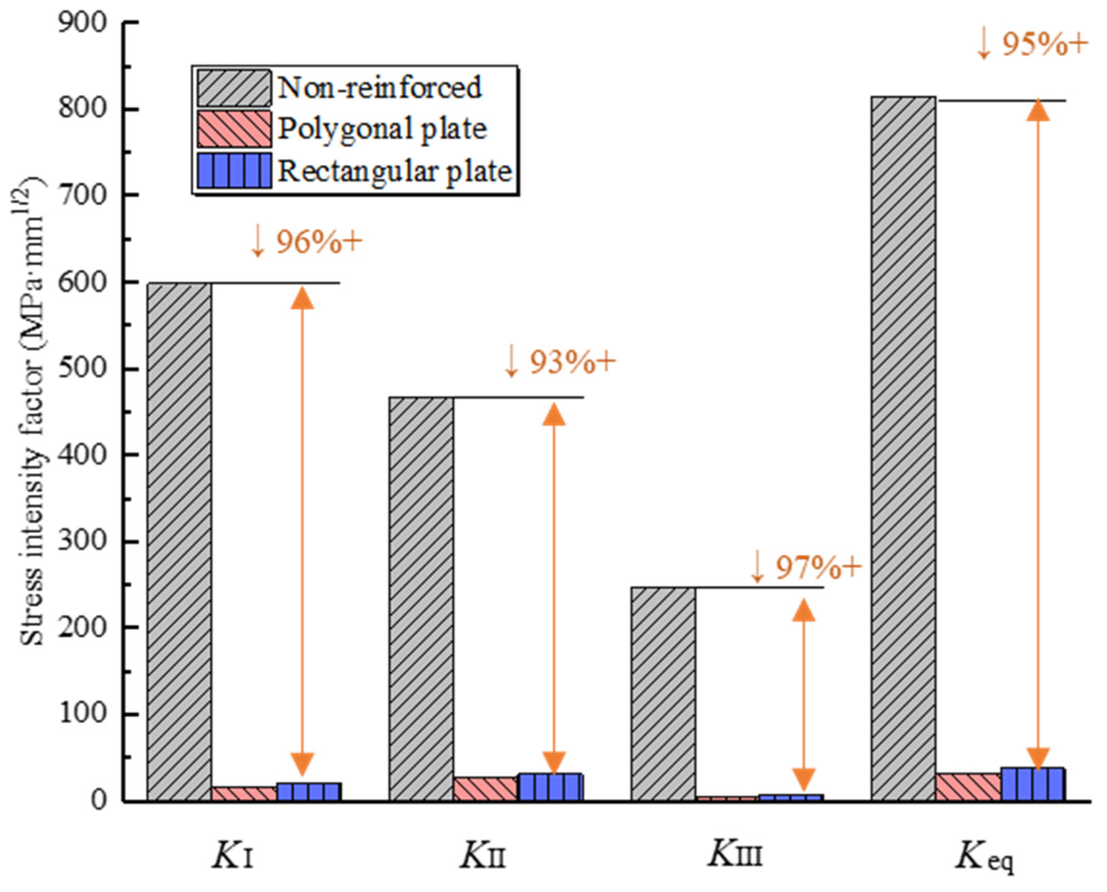
The stress intensity factors obtained via the finite element method are shown in
Figure 4. It was seen that the stress concentration at the crack tip was obvious before reinforcement. After the steel plate reinforcement, the stress concentration was reduced, and the stress intensity factors fell by more than 93%.
Keq before the reinforcement reached 813.68 MPa·mm
1/2, which decreased to 31.75 and 37.70 MPa·mm
1/2 respectively after being reinforced with polygonal plate and rectangular plate. The values of the stress intensity factors after polygonal plate reinforcement were slightly higher than those after rectangular plate reinforcement. The results indicated that, both polygonal plate reinforcement and rectangular plate reinforcement had a significant effect on hindering crack propagation. In addition, before reinforcement, the crack that grew obliquely from the diaphragm-to-rib weld was shown as a mixed mode crack.
3.2. Stress on Reinforced Side
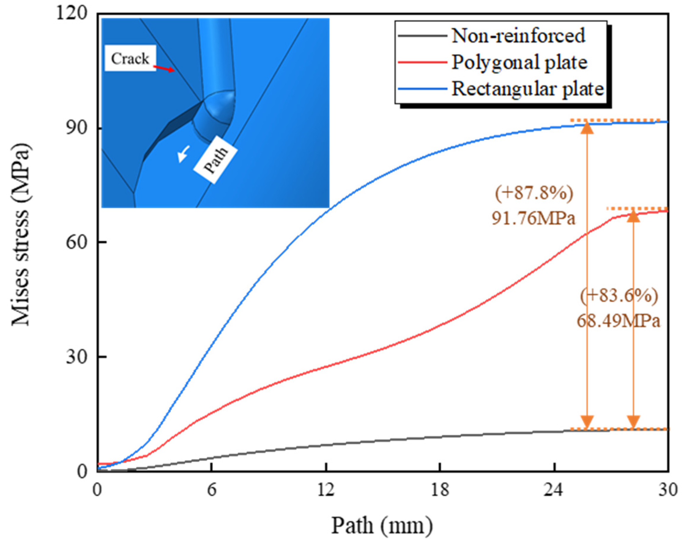
Steel plates took part in bearing loads with the component, while the local stiffness of the structure changed. Stresses at the arc notch on the reinforced side were extracted. The stress path and calculations are shown in
Figure 5.
As depicted, after reinforcement, an obvious increase in stress at the arc notch on the reinforced side occurred. Compared with the non-reinforced model, the maximum stress along the path was 68.49 MPa and 91.76 MPa respectively, for the polygonal steel plate and rectangular steel plate, which are increases of more than six times. The stress at the arc notch increased in a parabolic manner when using the rectangular steel plate. Both the polygonal steel plate and the rectangular steel plate caused an increase in stress at the arc notch on the reinforced side. As the crack top bore the majority of the load before reinforcement, the crack continued to propagate under the external force. After reinforcement, the steel plate bore part of the load and the rest was distributed to the arc notch causing a stress concentration at this location. The arc notch was also a typical fatigue detail in OSDs. Compared to the rectangular plate, the stress increase caused by the polygonal plate was smaller.
3.3. Stress on Non-Reinforced Side
Since the local stiffness of the structure changed after the steel plate reinforcement, the stress distribution on the non-reinforced side also changed; thus, it was crucial to analyze the effect on other locations of the component after the steel plate reinforcement. Therefore, the stresses at the weld toe and the arc notch on the non-reinforced side were extracted and are illustrated in
Figure 6.
As seen in
Figure 6, after steel plate reinforcement, the stresses at the diaphragm-to-rib weld toe and the arc notch on the non-reinforced side increased significantly. The maximum stress at the weld toe increased by more than 99 MPa; the maximum stress at the arc notch increased by more than 87 MPa. The calculations revealed that although the stress concentration at the crack tip improved, the change in local stiffness of the structure led to new high-stress situations at the diaphragm-to-rib weld toe on the non-reinforced side, which can cause fatigue cracking. Moreover, compared with the rectangular plate, the stress increment caused by the polygonal plate reinforcement was smaller, and the degree of stress concentration was lower.
4. Field Maintenance
4.1. Maintenance Schedule
Based on the numerical simulations above, a polygonal steel plate with a thickness of 8 mm was used in the field maintenance and the maintenance was conducted on a real bridge; the plane size is given in
Figure 7a. The material of the polygonal steel plate was Q345qD steel, which is the same as that of the real bridge.
A fatigue crack on the diaphragm-to-rib weld on the real bridge was chosen as the test object for this study. The crack was located on the upstream low lane, and its length was approximately 60 mm, as shown in
Figure 7b. When a vehicle passed, apparent dislocations could be observed on the crack surface.
During field maintenance, the upstream side of the diaphragm was selected as the reinforced surface, and the downstream side was the testing surface. The polygonal steel plate was pasted onto the reinforced surface with a structural adhesive, that would not cause damage to the original structure. Before bonding the steel plate, the surface was polished to remove the coating. The hypotenuse of the chamfer was fitted to the diaphragm-to-rib weld toe, as shown in
Figure 7c.
The stress data at the crack tip were recorded with a pasting strain rosette; its layout is shown in
Figure 8a. As depicted, the rosette contained three gauges named as CD1 (i.e., perpendicular to the crack), CD2 (i.e., 45° direction to the crack), and CD3 (i.e., parallel to the crack). Before pasting the strain rosette onto the base metal, the crack tip on the testing side was polished to remove the anticorrosive coating, as seen in
Figure 8b. The geometric size of the strain rosette was 10 mm × 10 mm. The resistance of the strain rosette was 120 Ω, while the sensitivity ratio was 2.0 ± 1.0%. Strain data before and after the reinforcement were recorded. The monitoring schemes for both tests were carried out from 5 p.m. to 6 p.m. This period was chosen as the traffic flow during this time was relatively large; the measurement time was about one hour.
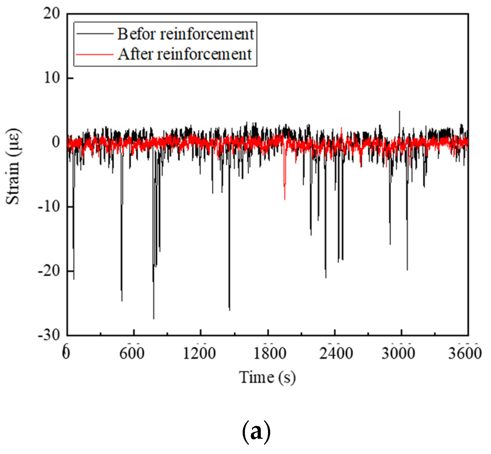
4.2. Strain–Time Curves
Figure 9 plots the strain records. Before reinforcement, the strain values of CD1 mainly ranged from −125 με to 9 με, and the strain values of CD2 mainly ranged from −6 με to 17 με, while the strain values of CD3 ranged from −27 με to 9 με. As shown, the measuring point area was under tension-compression cyclic loading, which was the main reason for fatigue crack growth.
After reinforcement, the strain values recorded in three directions were reduced significantly. The strain values of CD1 ranged from −30 με to 8 με, the strain values of CD2 ranged from −4 με to 2 με, and the strain values of CD3 ranged from −9 με to 3 με. It was observed that the deformation caused by vehicle passing over the crack was suppressed and that the crack propagation was hindered.
Based on the strain data obtained with a strain rosette, the maximum principal stress at the crack tip were calculated using Equation (2).
where
is the maximum principal stress, and
E is the Young’s modulus; here the value was 2.06 × 10
5 MPa,
v is Poisson’s ratio, in this case 0.3.
corresponds to the strain of CD1,
corresponds to the strain of CD2, and
corresponds to the strain of CD3.
Strain data within 30 min were processed and the results are given in
Figure 10. Since negative principal stress indicates compression at the crack tip, the data with negative principal stress were excluded. As shown in
Figure 10, the values of
decreased.
at the crack tip was significantly reduced after maintenance, and the maximum recorded
before reinforcement was 301.12 MPa. This decreased to 32.55 MPa after reinforcement, which was a decline of 89.4%. The stress concentration at the crack tip was improved with the steel plate reinforcement, fatigue performance was enhanced, and the fatigue life was prolonged.
4.3. Stress Range Spectrum
To achieve the stress range spectrum, the rain-flow counting method was adopted to handle the random stress time-history [
23]. The data collected with a strain rosette before and after the reinforcement were processed and the final result is presented in
Figure 11.
It was observed that, after polygonal steel plate reinforcement, the number of cycles at high stress ranges disappeared obviously. Meanwhile, the low stress ranges increased significantly, and the number of cycles within the [0, 5] MPa range increased a lot. This indicated that polygonal plate reinforcement improved the stress distribution at the crack tip, and the high–stress amplitudes were transformed to low stress amplitudes, resulting in the retardation of crack propagation.
4.4. Fatigue Damage Degree
During the process of bridge operation, each passing vehicle can impose different stress amplitudes, and the cumulative contribution to fatigue damage caused by these stress amplitudes can also vary. In general, a high−stress amplitude can cause a major fatigue damage increase, but the number of cycles with high–stress amplitudes is lower. Conversely, a low–stress amplitude makes a very small contribution to fatigue damage. Fatigue damage degree refers to the accumulation of fatigue damage during the cyclic vehicle loads.
Based on the stress range spectrums, Miner’s linear damage accumulating theory was used to calculate the fatigue damage degree using Equation (3) [
24].
where D is the fatigue damage degree; fatigue failure is considered to occur on the component when the value of D reaches to 1.
is the designed value of fatigue strength of the diaphragm-to-rib weld, here the value is 80 MPa, according to the Chinese standard [
25].
is the variable stress amplitude. In this case, the value refers to the median of each interval, for example, if the stress amplitude range is [5, 10] MPa, then the stress amplitude value is 7.5 MPa.
is the corresponding cycle number of stress amplitude.
The fatigue damage degrees before and after reinforcement were obtained and are listed in
Table 1. It appeared that the fatigue damage degree at the crack tip decreased sharply by 84.7% within one hour after reinforcement. Fatigue life before reinforcement was only 0.81 years, which rose to 5.28 years after reinforcement with an increase of more than five times. The result indicated that bonding a polygonal steel plate could significantly improve the stress concentration at the crack tip, hinder crack propagation effectively and prolong the fatigue life. The maintenance effect of polygonal steel plate reinforcement was proven.
5. Conclusions
In this work, numerical methods were used to compare and investigate the maintenance effects of two steel plate shapes. A field maintenance scheme was designed based on the simulated results. Steel plate reinforcement on a real bridge was conducted, and the maintenance effect was evaluated through analyzing stress distribution and fatigue damage degrees. The following conclusions can be drawn:
(1) Both polygonal steel plate and rectangular steel plates can significantly reduce the stress intensity factor and basically eliminate the stress concentration at the crack tip. Steel plate reinforcement causes changes in the stress distribution in other parts of the component, and a certain degree of stress concentration can occur in the diaphragm-to-rib weld on the non-reinforced side. Compared with the rectangular plate, the adverse effect caused by the polygonal plate is less.
(2) After reinforcement on a fatigue crack on a real bridge, the stress concentration at the crack tip was effectively improved. The number of cycles in high–stress ranges decreased significantly, whereas the number of cycles in low–stress ranges increased. Field monitoring demonstrated that the fatigue damage degree at the crack tip was reduced after reinforcement, indicating the effectiveness of polygonal steel plate reinforcement.
(3) The stiffness change caused by the steel plate reinforcement can lead to the risk of new fatigue cracks occurring on other parts of the bridge structure, emphasizing the importance of follow-up monitoring to verify the effect of the reinforcement.
Author Contributions
Conceptualization: X.D., Y.Z. and X.Z.; methodology: X.D., X.Z. and Z.Y.; software: C.M. and Z.Y.; testing: Y.G., C.M. and Y.Z.; validation: Y.G. and C.M.; formal analysis: X.Z. and Y.Z.; investigation: X.D. and Y.G.; resources: X.D. and Y.Z.; data curation: X.D., Y.G. and Y.Z.; writing—original draft: X.D.; writing—review and editing: X.Z. and C.M.; visualization: C.M. and Z.Y.; supervision: X.D.; project administration: X.D.; funding acquisition: X.D, Y.Z. and Z.Y. All authors have read and agreed to the published version of the manuscript.
Funding
The research reported herein was conducted as part of the research projects granted by the Academician Project Foundation of CCCC (grant No. YSZX-03-2020-01-B), the Youth Project Foundation of CCCC (grant No. 2021-ZJKJ-QNCX03), the Academician Project Foundation of CCCC (grant No.YSZX-03-2021-01-B), the National Key Research and Development Project (grant No. 2017YFE0128700) and the Natural Science Foundation of Jiangsu Province (grant No. BK2020042014). The assistances are gratefully acknowledged.
Institutional Review Board Statement
Not applicable.
Informed Consent Statement
Not applicable.
Data Availability Statement
Not applicable.
Conflicts of Interest
The authors declare no conflict of interest.
Nomenclature
| OSD | Orthotropic steel deck |
| FRP | Fiber reinforced polymer |
| CFRP | Carbon fiber reinforced polymer |
| CT | Compact tension |
| XFEM | EXtended finite element method |
References
- Ya, S.; Yamada, K.; Ishikawa, T. Fatigue Evaluation of Rib-to-Deck Welded Joints of Orthotropic Steel Bridge Deck. J. Bridge Eng. 2011, 18, 492–499. [Google Scholar] [CrossRef]
- Fisher, J.; Roy, S. Fatigue of steel bridge infrastructure. Struct. Infrastruct. Eng. 2011, 7, 457–475. [Google Scholar] [CrossRef]
- Guo, T.; Liu, Z.; Correia, J.; Jesus, A.M.P.D. Experimental study on fretting-fatigue of bridge cable wires. Int. J. Fatigue 2020, 131, 105321. [Google Scholar] [CrossRef]
- Meng, C.; Yuanzhou, Z.; Ji, B.; Yang, M. Study on fatigue performance of arc notch of diaphragm in steel box girder. Int. J. Steel Struct. 2022, 22, 1686–1694. [Google Scholar] [CrossRef]
- Yan, F.; Chen, W.; Lin, Z. Prediction of fatigue life of welded details in cable-stayed orthotropic steel deck bridges. Eng. Struct. 2016, 127, 344–358. [Google Scholar] [CrossRef]
- Wang, C.; Zhai, M.; Duan, M.; Wang, Y. Cold reinforcement and evaluation of steel bridges with fatigue cracks. J. Bridge Eng. 2018, 23, 04018014. [Google Scholar] [CrossRef]
- Guo, T.; Liu, J.; Deng, Y.; Zhan, Z. Fatigue Performance of Orthotropic Steel Decks with FRP Angles: Field Measurement and Numerical Analysis. J. Perform. Constr. Facil. 2019, 33, 04019042. [Google Scholar] [CrossRef]
- Fang, L.; Fu, Z.; Ji, B.; Kainuma, S. Research on mixed mode crack drilling under out-of-plane shear in steel bridge deck. Int. J. Fatigue 2022, 156, 106679. [Google Scholar] [CrossRef]
- Makabe, C.; Murdani, A.; Kuniyoshi, K.; Irei, Y.; Saimoto, A. Crack-growth arrest by redirecting crack growth by drilling stop holes and inserting pins into them. Eng. Fail. Anal. 2009, 16, 475–483. [Google Scholar] [CrossRef]
- Fu, Z.; Wang, Q.; Ji, B.; Yuanzhou, Z. Rewelding Repair Effects on Fatigue Cracks in Steel Bridge Deck Welds. J. Perform. Constr. Facil. 2017, 31, 04017094. [Google Scholar] [CrossRef]
- Miki, C.; Anami, K.; Higuchi, Y. Fatigue strength improvement by additional welding with low temperature transformation welding material. Proc. Jpn. Soc. Civ. Eng. 2002, 710, 311–319. [Google Scholar] [CrossRef] [PubMed]
- Yamada, K.; Ishikawa, T.; Kakiichi, T. Rehabilitation and improvement of fatigue life of welded joints by ICR Treatment. Adv. Steel Constr. 2015, 11, 294–304. [Google Scholar] [CrossRef]
- YuanZhou, Z.; Ji, B.; Fu, Z.; Ge, H. Fatigue performance of cracked rib-deck welded joint retrofitted by ICR technique. Int. J. Steel Struct. 2016, 16, 735–742. [Google Scholar] [CrossRef]
- Yuanzhou, Z.; Ji, B.; Fu, Z.; Kainuma, S.; Tsukamoto, S. Fatigue crack retrofitting by closing crack surface. Int. J. Fatigue 2019, 119, 229–237. [Google Scholar] [CrossRef]
- Lin, F.; Sun, J.; Nakamura, H.; Maeda, K. Fatigue crack repair using drilled holes and externally bonded CFRP strips. Rammed Earth Conserv. 2012, 267, 1308–1315. Available online: https://kozo.fpark.tmu.ac.jp/archive/data/Paper_III-3-5-53.pdf (accessed on 4 September 2023).
- Fang, L.; Yuanzhou, Z.; Yao, Y.; Fu, Z. Analysis of Steel Plate Crack Maintenance Effect Based on CT Model. J. Wuhan Univ. Technol. (Transp. Sci. Eng.) 2020, 44, 299–305. (In Chinese) [Google Scholar] [CrossRef]
- Lv, K. Research on Fatigue Cracking and Countermeasures for Orthotropic Deck; Changsha University of Science and Technology: Changsha, China, 2015. (In Chinese) [Google Scholar]
- Fu, Z.; Fang, L.; Wang, Y.; Ji, B. Stress Characteristics of the Weld Crack in Diaphragm-U Rib of Steel Bridge Deck after Repair. J. Henan Univ. (Nat. Sci.) 2019, 49, 340–346. (In Chinese) [Google Scholar] [CrossRef]
- Irwin, G. Analysis of stresses and strain near the end of a crack traversing in plate. J. Appl. Mech. 1957, 24, 361–365. [Google Scholar] [CrossRef]
- Wolf, E. Fatigue crack closure under cyclic tension. Eng. Fract. Mech. 1970, 2, 37–45. [Google Scholar] [CrossRef]
- Wang, L.; Wen, L.; Wang, J.; Tian, R. Implementations of parallel software for crack analyses based on the improved XFEM. Sci. Sin. (Technol.) 2018, 48, 1241–1258. (In Chinese) [Google Scholar] [CrossRef]
- BS 7910-2005; Guide to Methods for Assessing the Acceptability of Flaws in Metallic Structures. BSI Standards Limited: London, UK, 2005.
- Matsuishi, M.; Endo, T. Fatigue of metals subjected to varying stress. Jpn. Soc. Mech. Eng. 1968, 68, 37–40. [Google Scholar]
- Miner, M. Cumulative damage in fatigue. J. Appl. Mech. 1945, 12, A159–A164. [Google Scholar] [CrossRef]
- JTG D64-2015; Specifications for Design of Highway Steel Bridge. China Communications Press: Beijing, China, 2015.
| Disclaimer/Publisher’s Note: The statements, opinions and data contained in all publications are solely those of the individual author(s) and contributor(s) and not of MDPI and/or the editor(s). MDPI and/or the editor(s) disclaim responsibility for any injury to people or property resulting from any ideas, methods, instructions or products referred to in the content. |
© 2023 by the authors. Licensee MDPI, Basel, Switzerland. This article is an open access article distributed under the terms and conditions of the Creative Commons Attribution (CC BY) license (https://creativecommons.org/licenses/by/4.0/).


