
Localised Web Bearing Behaviour of Cold-Formed Austenitic Stainless-Steel Channels: Review of Design Rules and New Insight under Interior Loading
Abstract
:1. Introduction
2. Web Bearing Capacity Design of Cold-Formed Austenitic Stainless-Steel Channels
2.1. ASCE Specification
- IOF is Interior-One-Flange,
- EOF is End-One-Flange,
- ITF is Interior-Two-Flange,
- ETF is End-Two-Flange,
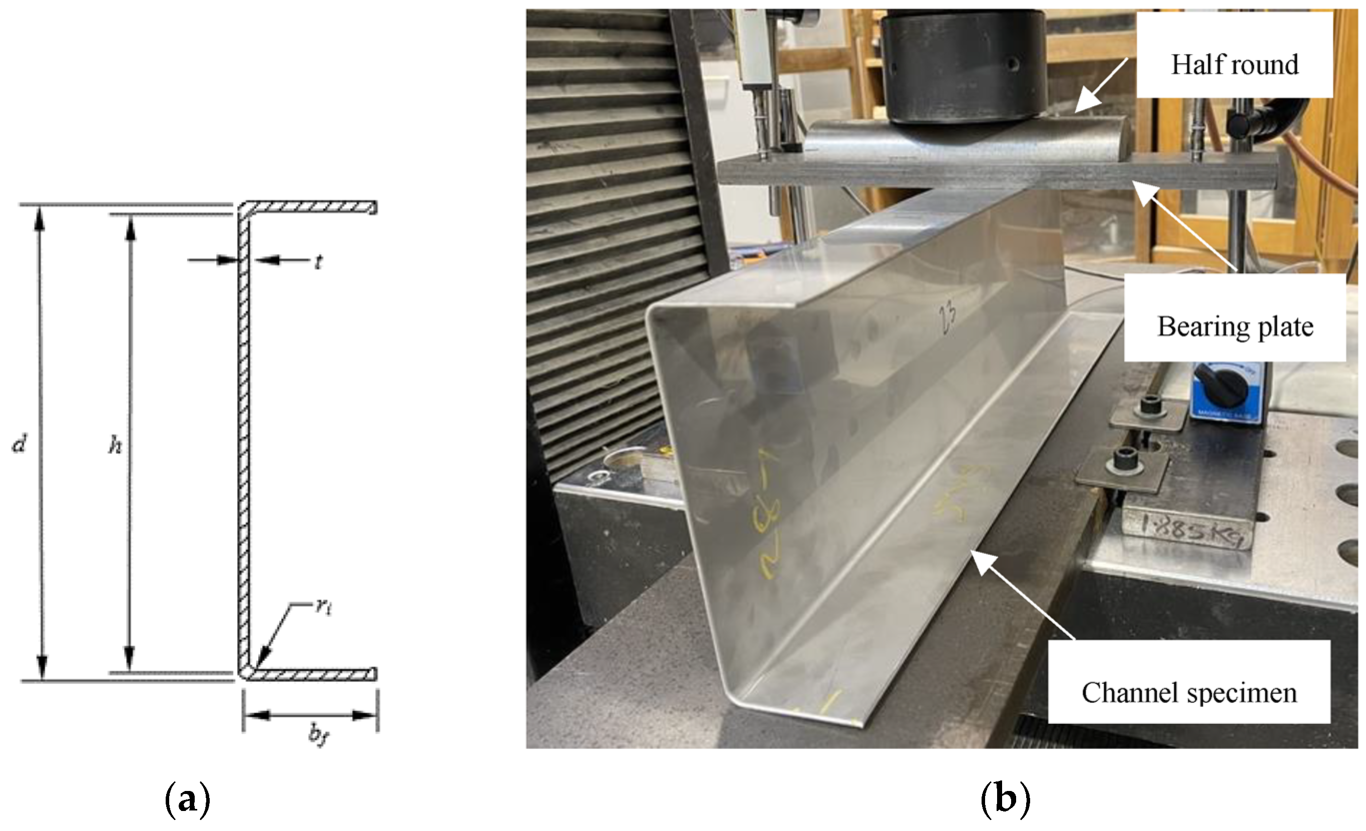
- h is the depth of the flat portion of the web measured along the plane of the web,
- Pn is the nominal localised bearing strength for unlipped channels,
- R is the inside bend radius,
- t is the web thickness,
- N is the actual length of the bearing.
2.2. European Code
- hw is the web height between the midlines of the flanges;
- r is the internal radius of the corners;
- θ is the angle of the web relative to the flanges (degrees).
- is the distance from loading to the closest end of the beam;
- is the nominal length of stiff bearing;
- is the yield strength of steel;
- is the partial safety factor,
- .
2.3. American Iron and Steel Institute Specification
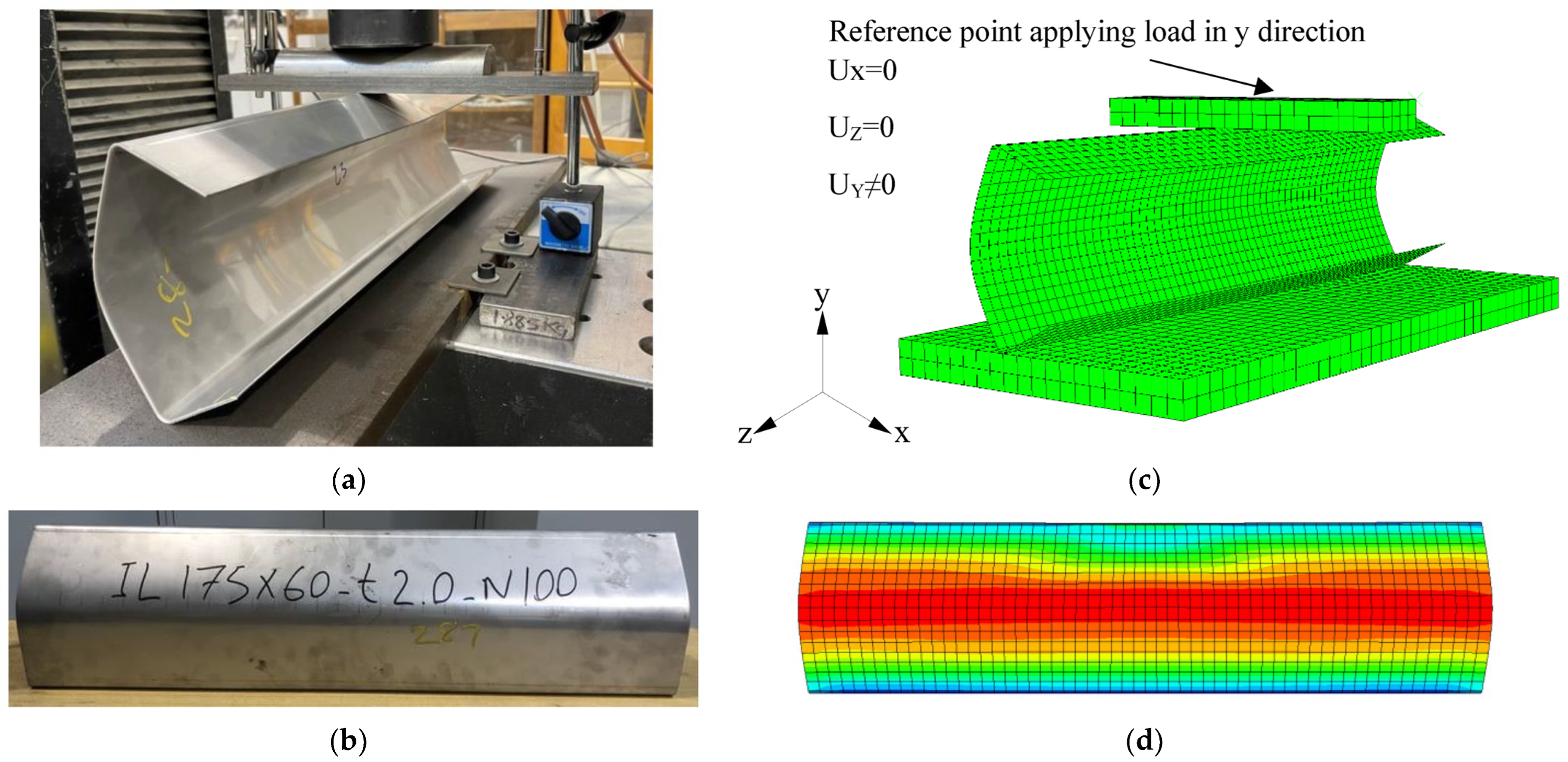
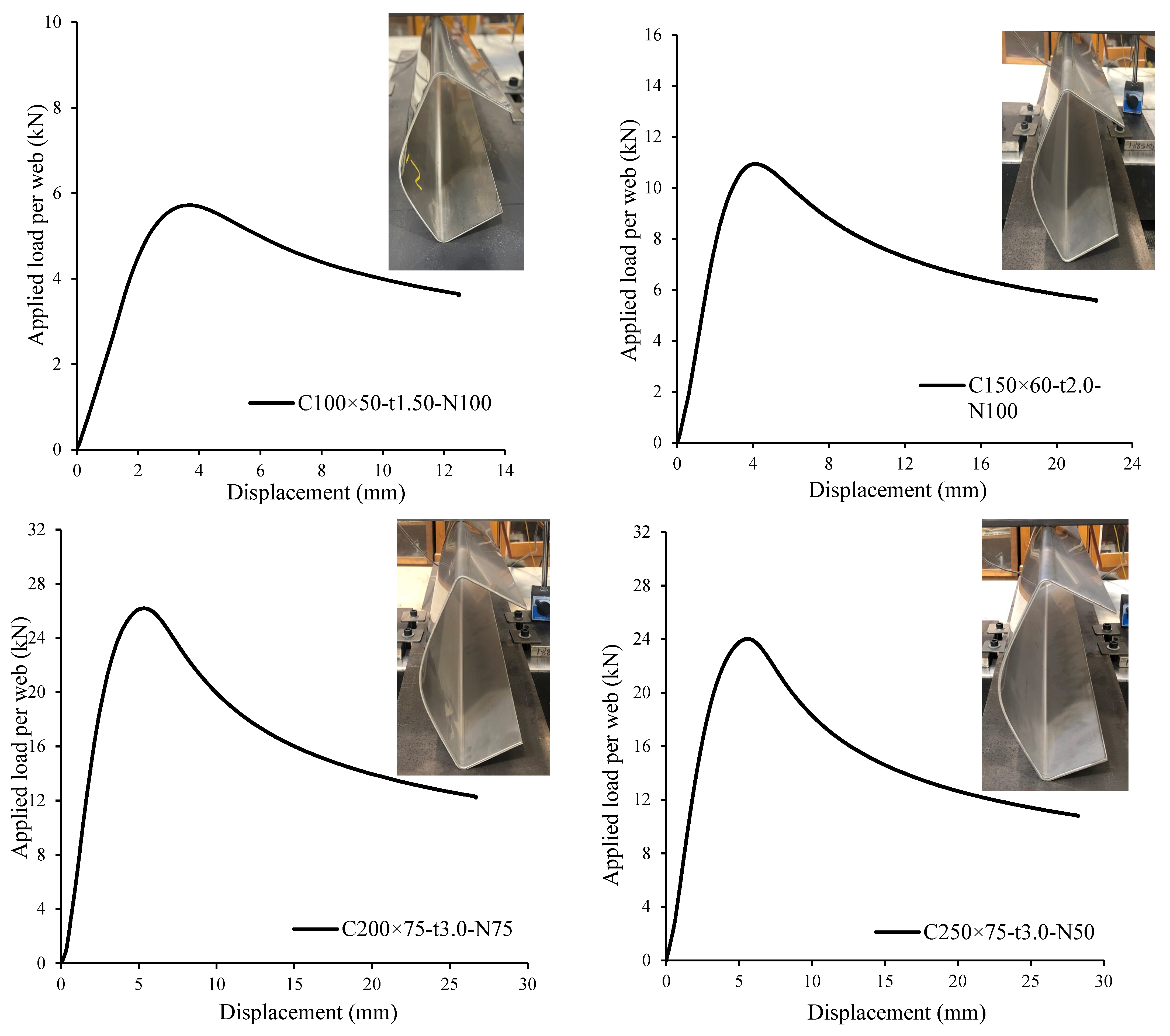
3. Experimental Investigation
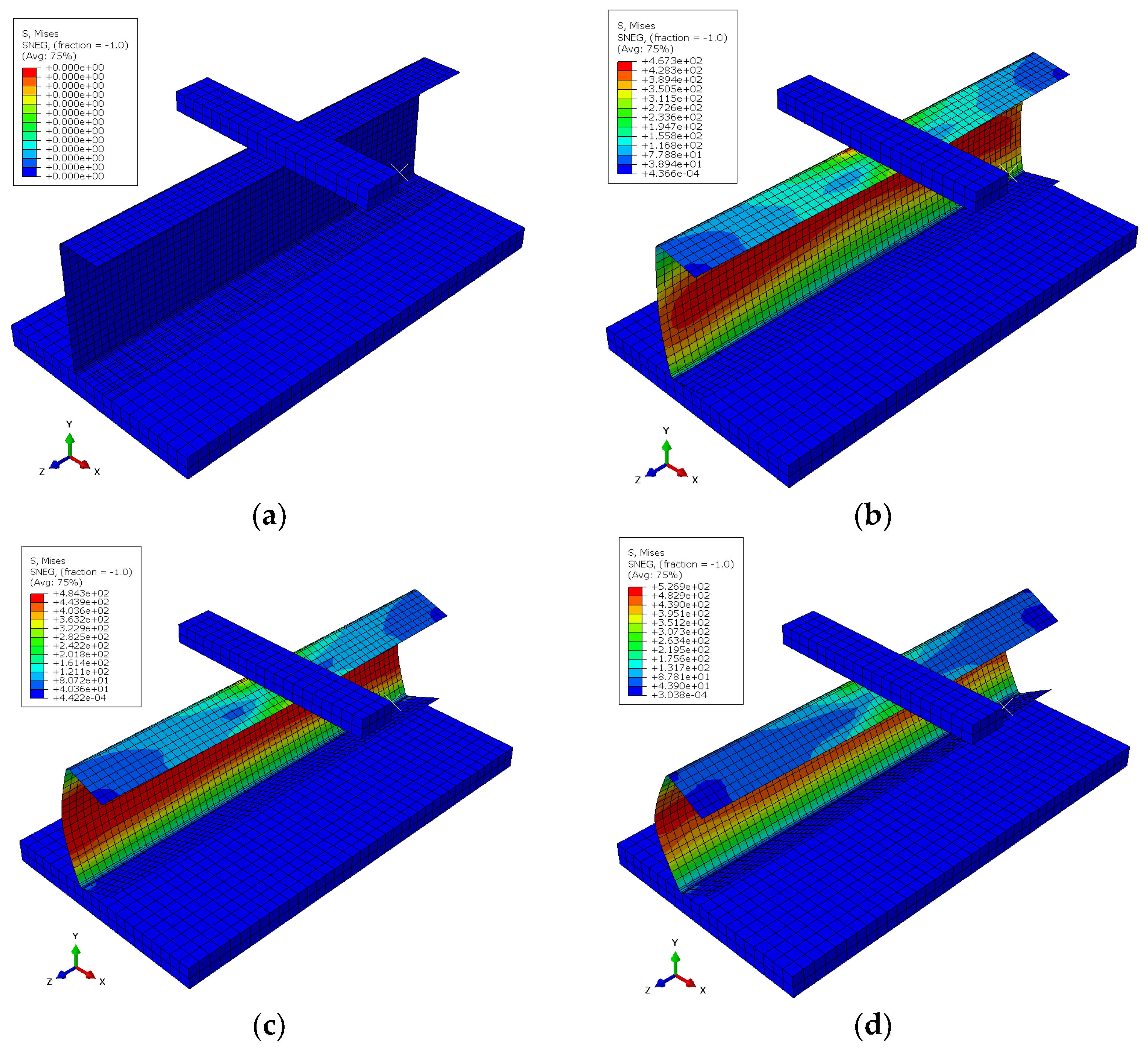
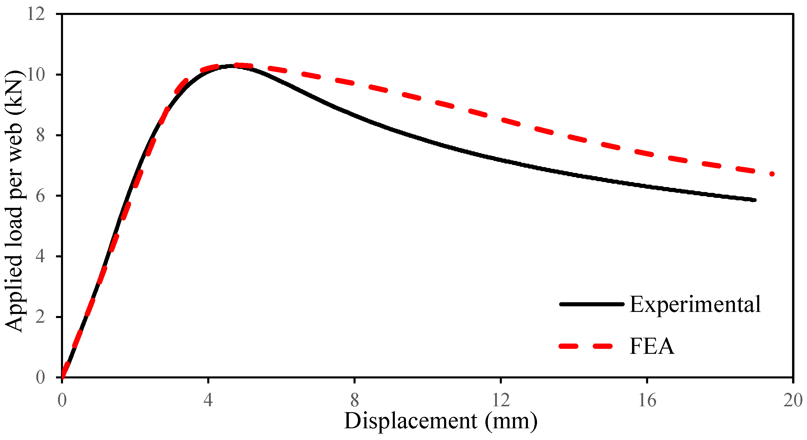
4. Numerical Investigation
5. Design Comparisons of Web Bearing Capacity with Current Design Codes
6. Conclusions
Author Contributions
Funding
Institutional Review Board Statement
Informed Consent Statement
Data Availability Statement
Acknowledgments
Conflicts of Interest
References
- Mohan, D.G.; Tomków, J.; Karganroudi, S.S. Laser Welding of UNS S33207 Hyper-Duplex Stainless Steel to 6061 Aluminum Alloy Using High Entropy Alloy as a Filler Material. Appl. Sci. 2022, 12, 2849. [Google Scholar] [CrossRef]
- Yu, J.; Ho, H. Microstructure and Mechanical Properties of (Ti,Nb)C Ceramic-Reinforced 316L Stainless Steel Coating by Laser Cladding. Appl. Sci. 2022, 12, 6684. [Google Scholar] [CrossRef]
- Gardner, L. Stability and design of stainless steel structures–Review and outlook. Thin-Wall. Struct. 2019, 141, 208–216. [Google Scholar] [CrossRef]
- Baddoo, N.R. Stainless steel in construction: A review of research, applications, challenges and opportunities. J. Constr. Steel Res. 2008, 64, 1199–1206. [Google Scholar] [CrossRef]
- Cashell, K.A.; Baddoo, N.R. Ferritic, Stainless steels in structural applications. Thin-Wall. Struct. 2014, 83, 169–181. [Google Scholar] [CrossRef]
- Korvink, S.A.; van den Berg, G.J. Web crippling of stainless steel cold-formed beams. In Proceedings of the 12th International Specialty Conference on Cold-Formed Steel Structures, St. Louis, MO, USA, 18–19 October 1994; University of Missouri-Rolla: St. Louis, MO, USA, 1994; pp. 551–569. [Google Scholar]
- Korvink, S.A.; van den Berg, G.J.; van der Merwe, P. Web crippling of stainless steel cold-formed beams. J. Constr. Steel Res. 1995, 34, 225–248. [Google Scholar] [CrossRef]
- Li, H.T.; Young, B. Cold-formed ferritic stainless steel tubular structural members subjected to concentrated bearing loads. Eng. Struct. 2017, 145, 392–405. [Google Scholar] [CrossRef]
- Cai, Y.; Young, B. Web crippling of lean duplex stainless steel tubular sections under concentrated end bearing loads. Thin-Wall. Struct. 2019, 134, 29–39. [Google Scholar] [CrossRef]
- Cai, Y.; Young, B. Cold-formed lean duplex stainless steel tubular members under concentrated interior bearing loads. J. Struct. Eng. 2019, 145, 04019056. [Google Scholar] [CrossRef]
- Yousefi, A.M.; Samali, B.; Yu, Y. Web bearing design of cold-formed austenitic stainless steel unlipped channels under localised interior loading. Thin-Wall. Struct. 2023, 191, 110946. [Google Scholar] [CrossRef]
- Yousefi, A.M.; Samali, B.; Hajirasouliha, I. Experimental and numerical investigations of cold-formed austenitic stainless steel unlipped channels under bearing loads. Thin-Wall. Struct. 2020, 152, 106768. [Google Scholar] [CrossRef]
- Yousefi, A.M.; Lim, J.B.P.; Clifton, G.C. Cold-formed ferritic stainless steel unlipped channels with web openings subjected to web crippling under interior-two-flange loading condition—Part I: Tests and finite element model validation. Thin-Wall. Struct. 2017, 116, 333–341. [Google Scholar] [CrossRef]
- Yousefi, A.M.; Lim, J.B.P.; Clifton, G.C. Cold-formed ferritic stainless steel unlipped channels with web openings subjected to web crippling under interior-two-flange loading condition—Part II: Parametric study and design equations. Thin-Wall. Struct. 2017, 116, 342–356. [Google Scholar] [CrossRef]
- Yousefi, A.M.; Lim, J.B.P.; Clifton, G.C. Web bearing capacity of unlipped cold-formed ferritic stainless steel channels with perforated web subject to end-two-flange (ETF) loading. Eng. Struct. 2017, 152, 804–818. [Google Scholar] [CrossRef]
- Yousefi, A.M.; Lim, J.B.P.; Clifton, G.C. Web crippling design of cold-formed ferritic stainless steel unlipped channels with fastened flanges under end-two-flange loading. J. Constr. Steel Res. 2019, 152, 12–28. [Google Scholar] [CrossRef]
- Yousefi, A.M.; Lim, J.B.P.; Uzzaman, A.; Lian, Y.; Clifton, G.C.; Young, B. Web crippling strength of cold-formed stainless steel lipped channel-sections with web openings subjected to Interior-One-Flange loading condition. Steel Compos. Struct. Int. J. 2016, 21, 629–659. [Google Scholar] [CrossRef]
- Yousefi, A.M.; Lim, J.B.P.; Uzzaman, A.; Lian, Y.; Clifton, G.C.; Young, B. Design of cold-formed stainless steel lipped channel-sections with web openings subjected to web crippling under End-One-Flange loading condition. Adv. Struct. Eng. 2017, 20, 1024–1045. [Google Scholar] [CrossRef]
- Yousefi, A.M.; Uzzaman, A.; Lim, J.B.P.; Clifton, G.C.; Young, B. Numerical investigation of web crippling strength in cold-formed stainless steel lipped channels with web openings subjected to interior-two-flange loading condition. Steel Compos. Struct. Int. J. 2017, 23, 363–383. [Google Scholar] [CrossRef]
- Yousefi, A.M.; Uzzaman, A.; Lim, J.B.P.; Clifton, G.C.; Young, B. Web crippling strength of cold-formed stainless steel lipped channels with web perforations under end-two-flange loading. Adv. Struct. Eng. 2017, 20, 1845–1863. [Google Scholar] [CrossRef]
- Yousefi, A.M.; Samali, B. Design of cold-formed ferritic stainless steel unlipped channels with offset web openings and unfastened flanges subject to web bearing failure under one-flange load scenarios. Structures 2020, 27, 194–211. [Google Scholar] [CrossRef]
- Yousefi, A.M.; Lim, J.B.P.; Clifton, G.C. Cold-formed ferritic stainless steel unlipped channels with web perforations subject to web crippling under one-flange loadings. Construct. Build. Mats. 2018, 191, 713–725. [Google Scholar] [CrossRef]
- Yousefi, A.M.; Lim, J.B.P.; Clifton, G.C. Web crippling strength of perforated cold-formed ferritic stainless steel unlipped channels with restrained flanges under one-flange loadings. Thin-Wall. Struct. 2019, 137, 94–105. [Google Scholar] [CrossRef]
- AS/NZS 4673:2001; Cold-Formed Stainless Steel Structures. Australian/New Zealand Standard (AS/NZS): Sydney, Australia, 2001.
- SEI/ASCE 8–02; Specification for the Design of Cold-Formed Stainless Steel Structural Members. American Society of Civil Engineers (ASCE): Reston, VA, USA, 2002.
- European Committee for Standardization (CEN). Eurocode 3: Design of Steel Structures—Part 1.4 (EN 1993-1-4). General Rules—Supplementary Rules for Stainless Steels; European Committee for Standardization (CEN): Brussel, Belgium, 2006. [Google Scholar]
- European Committee for Standardization (CEN). Eurocode 3: Design of Steel Structures—Part 1.3 (EN 1993-1-3). General Rules—Supplementary Rules for Cold-Formed Members and Sheeting; European Committee for Standardization (CEN): Brussel, Belgium, 2006. [Google Scholar]
- ABAQUS Inc. ABAQUS Analysis User’s Manual; Version 6.25; ABAQUS Inc.: Palo Alto, CA, USA, 2018. [Google Scholar]
- SEI/ASCE 8:2002; Specification for the Design of Cold-Formed Stainless Steel Structural Members. ANSI: Washington, DC, USA, 2002.
- EN 1993-1-4:2006; Eurocode 3—Design of Steel Structures—Part 1–4: General Rules—Supplementary Rules for Stainless Steels. iTeh, Inc.: Newark, DE, USA, 2006.
- AISI S100-16; American Iron and Steel Institute Specification (AISI), North American Specification for the Design of Cold-Formed Steel Structural Members. ANSI: Washington, DC, USA, 2016.
- Rezvani, F.H.; Yousefi, A.M.; Ronagh, H.R. Effect of span length on progressive collapse behaviour of steel moment resisting frames. Structures 2015, 3, 81–89. [Google Scholar] [CrossRef]
- Mohammadjani, C.; Yousefi, A.M.; Cai, S.Q.; Clifton, G.C.; Lim, J.B.P. Strength and stiffness of cold-formed steel portal frame joints using quasi-static finite element analysis. Steel Compos. Struct. Int. J. 2017, 25, 727–734. [Google Scholar]
- Natário, P.N.; Silvestre, N.; Camotim, D. Web crippling failure using quasi-static FE models. Thin-Wall. Struct. 2014, 84, 34–49. [Google Scholar] [CrossRef]
- Yousefi, A.M.; Lim, J.B.P.; Clifton, G.C. Web crippling behaviour of unlipped cold-formed ferritic stainless steel channels subject to one-flange loading. J. Struct. Eng. 2018, 144, 04018105. [Google Scholar] [CrossRef]
- Yousefi, A.M.; Samali, B.; Yu, Y. Shear Behaviour and design of cold-formed ferritic stainless steel channels with circular web openings. Structures 2021, 33, 4162–4175. [Google Scholar] [CrossRef]
- Yousefi, A.M.; Samali, B.; Yu, Y. Unified design equations for web crippling failure of cold-formed ferritic stainless steel unlipped channel-sections with web holes. J. Build. Eng. 2022, 45, 103685. [Google Scholar] [CrossRef]
- Zhang, C.; Duan, C.; Sun, L. Experimental investigation of FPS inter-storey isolation control for assembled steel structure with high aspect ratio. Structures 2023, 53, 550–567. [Google Scholar] [CrossRef]
- Yang, Y.; Lin, B.; Zhang, W. Experimental and numerical investigation of an arch–beam joint for an arch bridge. Arch. Civil Mech. Eng. 2023, 23, 101. [Google Scholar] [CrossRef]
- Zhai, S.Y.; Lyu, Y.F.; Cao, K.; Li, G.Q.; Wang, W.Y.; Chen, C. Seismic behavior of an innovative bolted connection with dual-slot hole for modular steel buildings. Eng. Struct. 2023, 279, 115619. [Google Scholar] [CrossRef]
- Walport, F.; Kucukler, M.; Gardner, L. Stability design of stainless steel structures. J. Struct. Eng. 2022, 148, 04021225. [Google Scholar] [CrossRef]
- Xing, Z.; Zhao, O.; Kucukler, M.; Gardner, L. Fire testing of austenitic stainless steel I-section beam–columns. Thin-Walled Struct. 2021, 164, 107916. [Google Scholar] [CrossRef]
- Arrayago, I.; Real, E.; Gardner, L.; Mirambell, E. The Continuous Strength Method for the design of stainless steel hollow section beam-columns. Eng. Struct. 2021, 238, 111981. [Google Scholar] [CrossRef]
- Dos Santos, G.B.; Gardner, L. Design recommendations for stainless steel I-sections under concentrated transverse loading. Eng. Struct. 2020, 204, 109810. [Google Scholar] [CrossRef]
- Wang, F.; Young, B.; Gardner, L. Experimental study of square and rectangular CFDST sections with stainless steel outer tubes under axial compression. J. Struct. Eng. 2019, 145, 04019139. [Google Scholar] [CrossRef]
- Tan, Q.H.; Gardner, L.; Han, L.H.; Song, T.Y. Fire performance of steel reinforced concrete-filled stainless steel tubular (CFSST) columns with square cross-sections. Thin-Walled Struct. 2019, 143, 106197. [Google Scholar] [CrossRef]
- Wang, F.; Young, B.; Gardner, L. Compressive testing and numerical modelling of concrete-filled double skin CHS with austenitic stainless steel outer tubes. Thin-Walled Struct. 2019, 141, 345–359. [Google Scholar] [CrossRef]
- Bu, Y.; Gardner, L. Local stability of laser-welded stainless steel I-sections in bending. J. Constr. Steel Res. 2018, 148, 49–64. [Google Scholar] [CrossRef]
- Dos Santos, G.B.; Gardner, L. Testing and numerical analysis of stainless steel I-sections under concentrated end-one-flange loading. J. Constr. Steel Res. 2019, 157, 271–281. [Google Scholar] [CrossRef]
- Yang, L.; Zhao, M.; Gardner, L.; Ning, K.; Wang, J. Member stability of stainless steel welded I-section beam-columns. J. Constr. Steel Res. 2019, 155, 33–45. [Google Scholar] [CrossRef]
- Bu, Y.; Gardner, L. Laser-welded stainless steel I-section beam-columns: Testing, simulation and design. Eng. Struct. 2019, 179, 23–36. [Google Scholar] [CrossRef]
- Afshan, S.; Zhao, O.; Gardner, L. Standardised material properties for numerical parametric studies of stainless steel structures and buckling curves for tubular columns. J. Constr. Steel Res. 2019, 152, 2–11. [Google Scholar] [CrossRef]
- Cai, Y.; Zhou, F.; Wang, L.; Young, B. Design of lean duplex stainless steel tubular sections subjected to concentrated end bearing loads at elevated temperatures. Thin-Walled Struct. 2021, 160, 107298. [Google Scholar] [CrossRef]
- Cai, Y.; Young, B. Web crippling design of lean duplex stainless steel tubular members under interior loading conditions. Eng. Struct. 2021, 238, 112192. [Google Scholar] [CrossRef]
- Li, H.T.; Young, B. Cold-formed stainless steel RHS members undergoing combined bending and web crippling: Testing, modelling and design. Eng. Struct. 2022, 250, 113466. [Google Scholar] [CrossRef]
- Li, H.T.; Zhan, K.J.; Young, B. Web crippling design of cold-formed high strength steel SHS and RHS at elevated temperatures. Thin-Walled Struct. 2022, 180, 109716. [Google Scholar] [CrossRef]
- Young, B.; Ellobody, E.; He, J. Web crippling tests on cold-formed high strength steel channel sections having different stiffened flanges and stiffened web. Thin-Walled Struct. 2023, 190, 110995. [Google Scholar] [CrossRef]
- Li, H.T.; Li, Q.Y.; Real, E.; Young, B. Web crippling resistances of cold-formed stainless steel sections: A proposal for EN 1993-1-4. J. Constr. Steel Res. 2023, 210, 108082. [Google Scholar] [CrossRef]


| Channel | Plate Length N (mm) | Web Height d (mm) | Flange Width bf (mm) | Web Thickness t (mm) | Fillet Radius r (mm) | Channel Length L (mm) | Experimental Ultimate Force FExp (kN) |
|---|---|---|---|---|---|---|---|
| C100×50-t1.50-N50 | 50 | 100.24 | 50.32 | 1.48 | 5.00 | 350.21 | 5.23 |
| C100×50-t1.50-N75 | 75 | 100.73 | 50.74 | 1.49 | 5.00 | 373.83 | 5.49 |
| C100×50-t1.50-N100 | 100 | 100.63 | 50.95 | 1.48 | 5.00 | 398.67 | 5.72 |
| C125×50-t1.50-N50 | 50 | 123.91 | 49.89 | 1.49 | 5.00 | 424.00 | 5.43 |
| C125×50-t1.50-N75 | 75 | 125.60 | 49.75 | 1.50 | 5.00 | 449.67 | 5.56 |
| C125×50-t1.50-N100 | 100 | 125.44 | 49.90 | 1.50 | 5.00 | 475.67 | 5.81 |
| C150×60-t2.0-N50 | 50 | 150.84 | 59.62 | 2.00 | 5.50 | 501.00 | 10.45 |
| C150×60-t2.0-N75 | 75 | 149.62 | 60.71 | 2.00 | 5.50 | 526.00 | 10.64 |
| C150×60-t2.0-N100 | 100 | 149.17 | 60.52 | 1.98 | 5.50 | 550.33 | 10.94 |
| C175×60-t2.0-N50 | 50 | 175.40 | 60.86 | 1.99 | 5.50 | 576.50 | 10.28 |
| C175×60-t2.0-N75 | 75 | 175.28 | 60.84 | 2.00 | 5.50 | 599.17 | 10.69 |
| C175×60-t2.0-N100 | 100 | 174.15 | 60.27 | 2.00 | 5.50 | 626.17 | 10.97 |
| C200×75-t3.0-N50 | 50 | 201.50 | 74.64 | 3.00 | 6.00 | 650.83 | 26.04 |
| C200×75-t3.0-N75 | 75 | 201.45 | 74.49 | 2.99 | 6.00 | 674.33 | 26.50 |
| C200×75-t3.0-N100 | 100 | 201.58 | 74.17 | 3.00 | 6.00 | 699.00 | 27.10 |
| C225×75-t3.0-N50 | 50 | 225.50 | 74.54 | 3.00 | 6.00 | 725.50 | 26.45 |
| C225×75-t3.0-N75 | 75 | 226.00 | 74.27 | 2.99 | 6.00 | 749.33 | 27.08 |
| C225×75-t3.0-N100 | 100 | 225.50 | 74.73 | 2.98 | 6.00 | 775.33 | 26.09 |
| C250×75-t3.0-N50 | 50 | 249.75 | 74.35 | 2.99 | 6.00 | 726.00 | 24.01 |
| C250×75-t3.0-N75 | 75 | 250.50 | 74.68 | 2.99 | 6.00 | 749.33 | 24.39 |
| C250×75-t3.0-N100 | 100 | 249.75 | 74.46 | 2.99 | 6.00 | 775.50 | 23.05 |
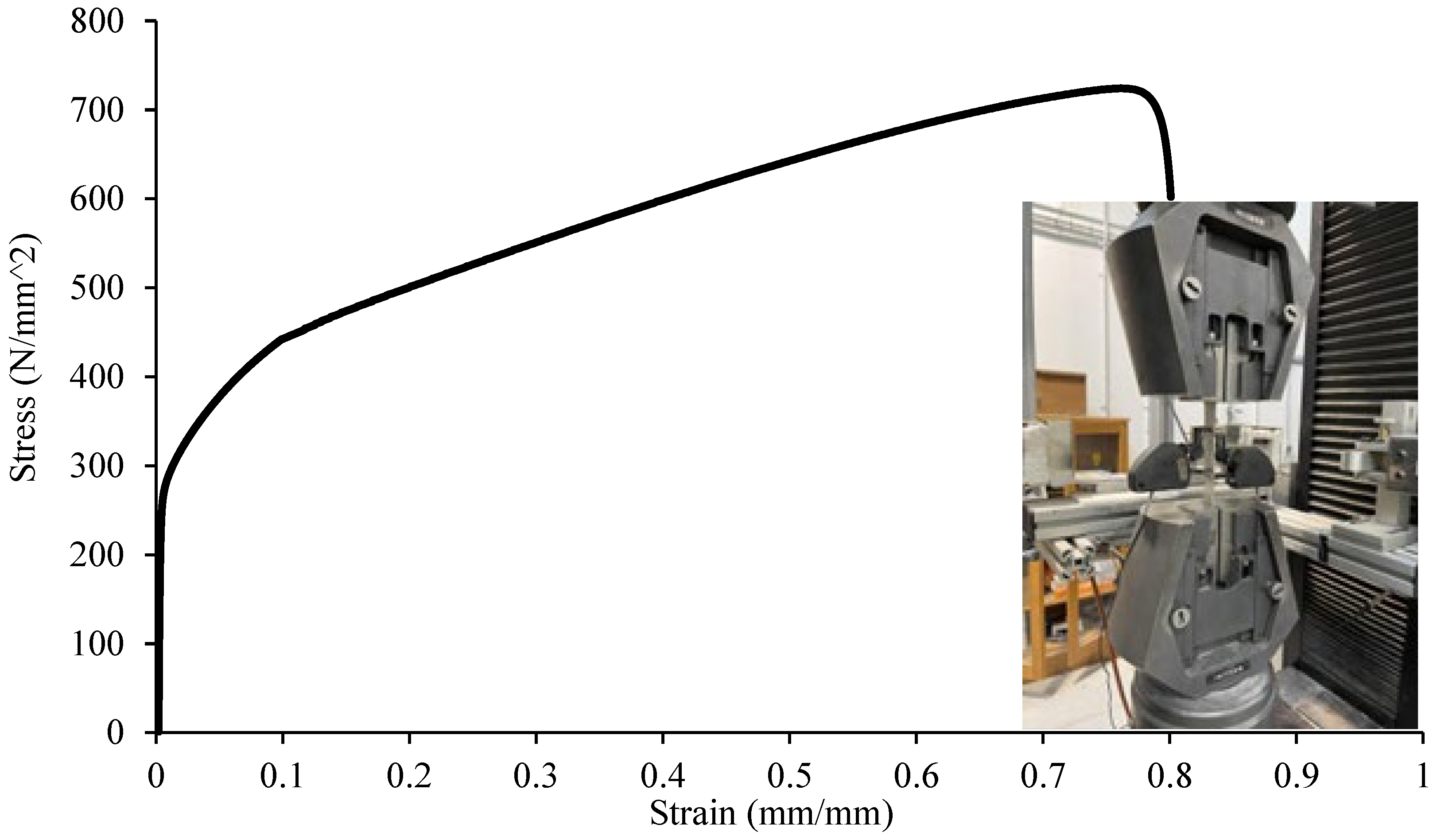
| Tensile Coupon | Base Metal Coupon Thickness (mm) | Gauge Width (mm) | Gauge Length (mm) | Elastic Modulus (MPa) | (MPa | (MPa) |
|---|---|---|---|---|---|---|
| 1.5 mm thickness | 1.48 | 20.0 | 50.0 | 200.0 | 264.0 | 594.0 |
| G316L-EN 1.4404 | 1.47 | 20.0 | 50.0 | 198.0 | 252.0 | 608.0 |
| 1.49 | 20.0 | 50.0 | 197.0 | 261.0 | 595.0 | |
| --- | --- | --- | 259.0 | 599.0 | ||
| 2.0 mm thickness | 1.97 | 20.0 | 50.0 | 198.0 | 280.0 | 695.0 |
| G304L-EN 1.4307 | 1.99 | 20.0 | 50.0 | 200.0 | 293.0 | 709.0 |
| 1.98 | 20.0 | 50.0 | 197.0 | 285.0 | 705.0 | |
| --- | --- | --- | 286.0 | 703.0 | ||
| 3.0 mm thickness | 2.98 | 20.0 | 50.0 | 197.0 | 291.0 | 730.0 |
| G304L-EN 1.4307 | 2.96 | 20.0 | 50.0 | 200.0 | 289.0 | 711.0 |
| 2.97 | 20.0 | 50.0 | 198.0 | 293.0 | 731.0 | |
| --- | --- | --- | 290.0 | 724.0 |
| Channel | Web Height Ratio (h/t) | Plate Length Ratio (N/t) | Fillet Radius Ratio (r/t) | Experimental Ultimate Load FExp (kN) | Finite Element Ultimate Load FFEA (kN) | Comparison FEXP/FFEA |
|---|---|---|---|---|---|---|
| C100×50-t1.50-N50 | 60.97 | 33.78 | 3.38 | 5.23 | 5.31 | 0.98 |
| C100×50-t1.50-N75 | 60.89 | 50.34 | 3.36 | 5.49 | 5.61 | 0.98 |
| C100×50-t1.50-N100 | 61.24 | 67.57 | 3.38 | 5.72 | 5.83 | 0.98 |
| C125×50-t1.50-N50 | 76.45 | 33.56 | 3.36 | 5.43 | 5.56 | 0.98 |
| C125×50-t1.50-N75 | 77.07 | 50.00 | 3.33 | 5.56 | 5.68 | 0.98 |
| C125×50-t1.50-N100 | 76.96 | 66.67 | 3.33 | 5.81 | 5.98 | 0.97 |
| C150×60-t2.0-N50 | 69.92 | 25.00 | 2.75 | 10.45 | 10.58 | 0.99 |
| C150×60-t2.0-N75 | 69.31 | 37.50 | 2.75 | 10.64 | 10.72 | 0.99 |
| C150×60-t2.0-N100 | 69.78 | 50.51 | 2.78 | 10.94 | 10.99 | 1.00 |
| C175×60-t2.0-N50 | 82.61 | 25.13 | 2.76 | 10.28 | 10.36 | 0.99 |
| C175×60-t2.0-N75 | 82.14 | 37.50 | 2.75 | 10.69 | 10.74 | 1.00 |
| C175×60-t2.0-N100 | 81.58 | 50.00 | 2.75 | 10.97 | 11.05 | 0.99 |
| C200×75-t3.0-N50 | 63.17 | 16.67 | 2.00 | 26.04 | 26.12 | 1.00 |
| C200×75-t3.0-N75 | 63.36 | 25.08 | 2.01 | 26.50 | 26.63 | 1.00 |
| C200×75-t3.0-N100 | 63.19 | 33.33 | 2.00 | 27.10 | 27.19 | 1.00 |
| C225×75-t3.0-N50 | 71.17 | 16.67 | 2.00 | 26.45 | 26.31 | 1.01 |
| C225×75-t3.0-N75 | 71.57 | 25.08 | 2.01 | 27.08 | 26.90 | 1.01 |
| C225×75-t3.0-N100 | 71.64 | 33.56 | 2.01 | 26.09 | 25.94 | 1.01 |
| C250×75-t3.0-N50 | 79.52 | 16.72 | 2.01 | 24.01 | 23.61 | 1.02 |
| C250×75-t3.0-N75 | 79.77 | 25.08 | 2.01 | 24.39 | 24.11 | 1.01 |
| C250×75-t3.0-N100 | 79.52 | 33.44 | 2.01 | 23.05 | 22.41 | 1.03 |
| Mean | 0.99 | |||||
| COV | 0.01 | |||||
| Reliability | 2.61 |
| Channel | Failure Load | Single Web Bearing Capacity | Comparison | ||
|---|---|---|---|---|---|
| FF (kN) | FASCE (kN) | FEURO (kN) | FF/FASCE | FF/FEURO | |
| C100×50-t1.50-N50 | 5.23 | 9.29 | 8.32 | 0.56 | 0.63 |
| C100×50-t1.50-N75 | 5.49 | 9.63 | 8.62 | 0.57 | 0.64 |
| C100×50-t1.50-N100 | 5.72 | 9.67 | 8.66 | 0.59 | 0.66 |
| C125×50-t1.50-N50 | 5.43 | 8.90 | 7.97 | 0.61 | 0.68 |
| C125×50-t1.50-N75 | 5.56 | 9.20 | 8.24 | 0.60 | 0.67 |
| C125×50-t1.50-N100 | 5.81 | 9.39 | 8.41 | 0.62 | 0.69 |
| C150×60-t2.0-N50 | 10.45 | 18.29 | 16.39 | 0.57 | 0.64 |
| C150×60-t2.0-N75 | 10.64 | 18.62 | 16.68 | 0.57 | 0.64 |
| C150×60-t2.0-N100 | 10.94 | 18.47 | 16.55 | 0.59 | 0.66 |
| C175×60-t2.0-N50 | 10.28 | 17.24 | 15.44 | 0.60 | 0.67 |
| C175×60-t2.0-N75 | 10.69 | 17.73 | 15.89 | 0.60 | 0.67 |
| C175×60-t2.0-N100 | 10.97 | 18.05 | 16.17 | 0.61 | 0.68 |
| C200×75-t3.0-N50 | 26.04 | 44.52 | 39.89 | 0.58 | 0.65 |
| C200×75-t3.0-N75 | 26.50 | 44.65 | 40.01 | 0.59 | 0.66 |
| C200×75-t3.0-N100 | 27.10 | 45.46 | 40.74 | 0.60 | 0.67 |
| C225×75-t3.0-N50 | 26.45 | 43.23 | 38.74 | 0.61 | 0.68 |
| C225×75-t3.0-N75 | 27.08 | 43.32 | 38.81 | 0.63 | 0.70 |
| C225×75-t3.0-N100 | 26.09 | 43.46 | 38.94 | 0.60 | 0.67 |
| C250×75-t3.0-N50 | 24.01 | 41.59 | 37.26 | 0.58 | 0.64 |
| C250×75-t3.0-N75 | 24.39 | 41.99 | 37.62 | 0.58 | 0.65 |
| C250×75-t3.0-N100 | 23.05 | 42.48 | 38.06 | 0.54 | 0.61 |
| Mean value, (Pm) | 0.59 | 0.66 | |||
| Coefficient of variation, (Vp) | 0.04 | 0.03 | |||
| Reliability | 0.42 | 0.88 | |||
Disclaimer/Publisher’s Note: The statements, opinions and data contained in all publications are solely those of the individual author(s) and contributor(s) and not of MDPI and/or the editor(s). MDPI and/or the editor(s) disclaim responsibility for any injury to people or property resulting from any ideas, methods, instructions or products referred to in the content. |
© 2023 by the authors. Licensee MDPI, Basel, Switzerland. This article is an open access article distributed under the terms and conditions of the Creative Commons Attribution (CC BY) license (https://creativecommons.org/licenses/by/4.0/).
Share and Cite
Yousefi, A.M.; Samali, B.; Yu, Y. Localised Web Bearing Behaviour of Cold-Formed Austenitic Stainless-Steel Channels: Review of Design Rules and New Insight under Interior Loading. Appl. Sci. 2023, 13, 10696. https://doi.org/10.3390/app131910696
Yousefi AM, Samali B, Yu Y. Localised Web Bearing Behaviour of Cold-Formed Austenitic Stainless-Steel Channels: Review of Design Rules and New Insight under Interior Loading. Applied Sciences. 2023; 13(19):10696. https://doi.org/10.3390/app131910696
Chicago/Turabian StyleYousefi, Amir M., Bijan Samali, and Yang Yu. 2023. "Localised Web Bearing Behaviour of Cold-Formed Austenitic Stainless-Steel Channels: Review of Design Rules and New Insight under Interior Loading" Applied Sciences 13, no. 19: 10696. https://doi.org/10.3390/app131910696