Article

Determination of Corrosion Rate in Galvanized Pipes in Centralized Hot Water Supply Systems

by
Nikolay Makisha
1,* and
Valentin Chukhin
2
1
Research and Education Centre “Water Supply and Wastewater Treatment”, Moscow State University of Civil Engineering, 26, Yaroslaskoye Highway, Moscow 129337, Russia
2
Department of Water Supply and Wastewater Treatment, Moscow State University of Civil Engineering, 26, Yaroslaskoye Highway, Moscow 129337, Russia
*
Author to whom correspondence should be addressed.
Appl. Sci. 2023, 13(19), 10564; https://doi.org/10.3390/app131910564
Submission received: 25 August 2023 / Revised: 20 September 2023 / Accepted: 20 September 2023 / Published: 22 September 2023
(This article belongs to the Special Issue Corrosion Inhibitors and Protective Coatings)

Abstract

:
To counteract possible corrosion, steel pipes are coated with a protective layer of zinc with a thickness of 20 to 85 microns, depending on the requirements of regulatory documentation. It is proven that hot-deposited zinc can effectively protect steel surfaces for 20 to 120 years. However, in centralized hot water supply (CHWS) systems, the period of protective action can decrease to two to three years, with further damage to the zinc layer and the appearance of fistulas. In order to counteract adverse factors, it is necessary to take into account the operating mode and design features of the system, the properties of the coating, and the environment in which the pipes operate. In this article, the main attention is paid to the study of the behavior of zinc coating. The protective properties and corrosion rate of zinc coating in tap water were evaluated. It was established that the protective effect of zinc is effectively manifested in the ratio of the protected area to the unprotected, as SZn/SFe ≥ 9:1. The influence of iron-containing sediment, when it accumulates in the pipes of a CHWS system, on the corrosion rate of the zinc coating was studied. It was also noted that the corrosion rates of the new zinc coating and uncoated steel pipe measured in short-term tests differed slightly.

1. Introduction

Galvanized pipes in water supply systems have been used for a long time; however, there is practically no information about the mechanism of the initial destruction of the coating or quantitative indicators on the corrosion rate of zinc in tap water. Before the proposed application, galvanized steel pipes may be stored in contact with air for some time. In relatively dry air, the zinc surface is covered with a zinc oxide film, and corrosion is practically absent.
If the humidity of the air is high enough, the process of electrochemical corrosion begins in the pores of the coating. An oxidizing reaction takes place on zinc (anode); zinc is ionized (dissolved) and turns into hydroxide and then into zinc carbonate. When the zinc coating is damaged, a conjugate reaction of oxygen reduction to the hydroxide ion (OH) occurs on the iron. Zinc, as a more electronegative metal, acts as an anode. At the same time, iron is under cathodic protection and does not corrode as long as the zinc coating is involved in the corrosion process [1]. However, there is almost no information in the literature on how far the protective effect of zinc extends in relation to the unprotected surface of a steel pipe.
In Russia, the production of steel pipes is regulated by the standards relating to water and gas pipelines [2] and electric-welded straight-seam pipes [3], on which a zinc coating is applied. According to [2], the coating of galvanized water pipes should be solid, and the thickness of the zinc layer should be at least 30 microns. In accordance with [4], the minimum thickness of the zinc layer was increased to 45–55 microns, depending on the diameter and thickness of the pipe wall. The standard [4] establishes general requirements for protective coatings applied by hot-dip galvanizing at temperatures of 430–460 °C, as well as requirements for the base metal and coating quality control methods. The calculated values of zinc coating thickness and the rate of its destruction may be helpful in predicting the service life of galvanized pipes.
Hot-deposited zinc effectively protects steel products for 20 to 120 years [1]. However, in some cases, the service life of galvanized steel pipes is two to three years due to pitting corrosion. This is especially true for centralized hot water supply systems. In terms of corrosion resistance, galvanized pipes occupy an intermediate position between uncoated steel and copper pipes.
To assess the kinetics of the destruction of the zinc coating under operating conditions, samples made from sections of galvanized pipes were installed on sections of hot water supply systems in Moscow using Volga water. A year later, the change in thickness of the zinc coating on the samples and galvanized pipes was determined. In addition, the proportion of the surface on which complete destruction of the zinc coating occurred was defined. The tests showed that the zinc coating was destroyed most quickly within the first few months of operation. So, in the first, second, and third months, the thickness of the zinc coating decreased, respectively, by 17, 9, and 6%, whereas in the next nine months, it decreased by 1%. This may be due to the precipitation of an insoluble sediment on the surface of the pipes, which increased the electrical resistance in the circuit comprising the anode, pipe material, cathode, and water containing oxygen.
However, if there are areas with a coating thickness about three times lower than the average, the coating on these areas is completely destroyed within the initial period of operation. Such areas (with a completely destroyed coating) can be found within three months of operation. Ensuring the uniformity of the zinc coating in thickness, with an average thickness of at least 70 microns, would contribute to the greater durability of pipes [5,6].
The results of surveys of centralized hot water supply (CHWS) systems located in residential buildings in which pipes began to fail within 2–3 years have been published in a number of studies [6,7]. Examples of abnormally high corrosion rates in galvanized pipes can be found in various studies. Thus, corrosion defects in hot water installations in Gdansk–Wrzeszcz (Poland) are similar to those described above [8]. The zinc coating was completely destroyed within 3–4 years. The reason was the high level of oxygen and aggressive CO2 in the water, as well as the content of chloride and sulfate ions of a total amount of more than 50 mg/L. The temperature of hot water and especially temperature differences are also of great importance since they are a source of cracks and destruction of the layers of corrosion products with protective properties. Another study showed that maintaining a constant water temperature below 55 °C at a pH of 7.4–7.8 may be one of the most effective ways to reduce the corrosion rate [8]. The maximum corrosion rate of the zinc coating is observed at a temperature of 70 °C [9].
The reasons for the high rate of corrosion of galvanized pipes in hot water systems, in addition to the quality of the source water, include the following:
  • Application of various types of pipe materials, including copper, in the CHWS system [10];
  • Welding of galvanized pipes without complying with the requirements of the standard;
  • Microbiological corrosion [11];
  • Current leakage [12].
The main reason for the accelerated rate of corrosion is the high concentration of dissolved oxygen and carbon dioxide in the water.
According to the literature data, when the water temperature increases from 10 to 60 °C, the oxygen content in the water at atmospheric pressure decreases by about three times. It should be noted that in a closed system, such as a CHWS system, water is oversaturated with oxygen and carbon dioxide, which are actively involved in the corrosion process. However, all of these factors have the same effect on pipes if we are talking about the hot water supply system in the same building where cases of abnormally high corrosion rates of galvanized pipes are observed. Consequently, there are factors that are not taken into account acting locally on limited areas of the inner surface of pipes and leading to a high rate of corrosion.
When studying the protective properties of zinc, it was found that zinc, when destroyed, prevents corrosion of the protected metal. This mechanism, with the direct contact of two metals and the presence of a conductive liquid, can act over long distances and is called sacrificial corrosion. On the other hand, it was also noted that the released zinc can be deposited on the surface of the protected metal in the immediate vicinity. This mechanism is called barrier protection [13,14,15,16].
Research by Saeedikhani et al. revealed the modeling of the mechanism of anticorrosive protection of a steel substrate covered with a zinc primer (96% zinc in mass) that was damaged by scratches [17]. The scratch was a 500-micron line located in the middle and along the entire length of the sample. The results showed that although the middle part of the scratch was protected by sacrificial protection, at the ends of the scratch, local cathodic deposition of zinc led to barrier protection due to changes in the concentration of dissolved oxygen.
In studying the local pH change in the scratch area in the period from 2 h to 96 h, the authors conclude that the mechanisms of sacrificial and barrier protection exist together along the scratch surface. The high alkalinity above the scratch center demonstrates that this area is under active sacrificial protection. Small areas near the corners of the scratches that are quite acidic, i.e., pH 5.5–6.5, are the areas under barrier protection where a layer of corrosion products is densely formed.
Flat samples of electrolytic zinc were used by immersing them for periods of 8, 10, 30, and 90 days in Caribbean Sea water to study the corrosion rate and determine the composition of compounds formed during zinc corrosion [18]. The experiment was carried out under static conditions at a temperature of 21 °C. It was found that Zn2+ ions released from the anode sites interacted with OH ions formed at the cathode sites, which led to the formation of poorly soluble Zn(OH)2. Due to the corrosion reaction, the initial pH of seawater decreased to 4.4 at the anode sites due to the hydrolysis of metal ions. This fact led to the formation of a complex of various zinc corrosion products that consumed at least part of the OH- ions formed at the cathode.
The results presented in the article showed that the rate of removal of zinc ions increased from 3.20 g/m2 after 8 days (which corresponds to a zinc corrosion rate of 0.0167 gm−2h−1) to 4.80 g/m2 (0.0067 gm−2h−1) after 30 days, when the corrosion potential reached the greatest negative value. After 90 days, zinc removal decreased to 4.50 g/m2 (0.0021 gm−2h−1).
The dependence of the corrosion rate of zinc in distilled water on temperature was estimated in [19]. At 60 °C, the corrosion rate was 58 g/m2 per day (or 2.42 gm−2h−1). The beginning of intensive corrosion of the steel base of galvanized pipes is, as a rule, indicated when consumers receive drinking water of a rusty color. The initial accumulation of iron in the hot water system is facilitated by the following:
  • Increased (more than 0.3 mg/L) iron content in the cold water that enters the water heaters;
  • Low water consumption compared to the designed value;
  • Pipe areas that are not protected with zinc, especially the ends with their threaded connections;
  • Steel and cast-iron shut-off valves without coating;
  • A large length of pipelines;
  • An increase in the temperature of the hot water.
If measures are not taken to prevent corrosion, sediment accumulates on horizontal sections of pipes with low water flow velocity as well as in dead ends, for example, in uninhabited apartments or on sections of risers with drain taps. In this case, subsedimentary corrosion may occur. A sharp increase in the water velocity causes sediment churning and the flow of rusty water to consumers through water intake devices.
It is known from the theory of corrosion processes that some ions, such as Fe3+, Cu2+, and Hg+, are depolarizers [7,20], i.e., they are able to accept electrons and recover. In the sediment layer, some of the iron is in ionic form. At the same time, the concentration of trivalent iron, Fe3+, has higher values than the concentration of iron in tap water entering the water supply system of residential buildings from the outdoor city water supply.
Therefore, the purpose of this study was to assess the effect of iron-containing sediment on the corrosion rate of zinc coatings and to study the protective effect of zinc in relation to an unprotected surface.

2. Materials and Methods

To check the corrosion mechanism of galvanized steel pipes in the laboratory of the Moscow State University of Civil Engineering, studies were conducted in conditions as close as possible to operational ones. The experiments were carried out on tap water in Moscow. The water quality during the experiments was as follows:
  • pH = 7.9.
  • The temperature of cold water (tcw) was 14–16 °C.
  • The temperature of hot water (thw) was 45–47 °C.
  • Total alkalinity (AT) was 2.5 meq/L.
  • Total hardness (GH) was 2.7 meq/L.
  • The content of calcium (Ca2+) was 1.84 meq/L.
  • Total salinity was 210 mg/L.
According to the Langelier and Risner indices (LSI and RSI, respectively), water can be classified as weakly corrosive and capable of the deposition of calcium carbonate.
Pipe samples for analysis were made of steel pipe with a diameter of 15 mm and a wall thickness of 2.8 mm [2]. The zinc coating was applied by hot-dip galvanizing. The chemical composition of the sediment on the surface of the samples was studied using a scanning electron microscope (Quanta FEI 250, PHILIPS/FEI, Hillsborough, OR, USA) and energy dispersive spectroscopy (EDAX) at different values of accelerating voltage. The secondary electrons (SE) type of signal was used in the research.
The corrosion rate was calculated based on the mass loss of the samples. Each pipe sample was weighed on a scale (Model AND GR-200, accuracy up to the fourth decimal place) before being inserted under the stream of hot water. After the exposure, the sample was dried at room temperature and reweighed. The difference between the two values of the sample mass (before and after the exposure) was the mass loss, which was related to the time of exposure to obtain values of corrosion rate.
For a possible comparison of the results obtained by different authors, the corrosion rate values had the same dimension.

3. Results and Discussion

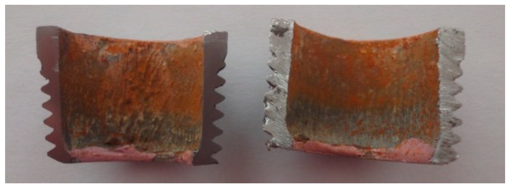
3.1. Determination of the Protective Effect and Corrosion Rate of Zinc

Experiments to determine the barrier role of zinc coating and the corrosion rate of galvanized pipes were carried out in hot water. A sample of a galvanized pipe with a diameter (DN) of 15 mm (Figure 1a) was placed in a container under a hot water jet with a temperature of 50 ± 2 °C for 4 h. The sample was sanded on one end and varnished on the other to prevent corrosion. The areas of surfaces coated and uncoated with zinc in the experiment were treated as SZn/SFe = 9:1. The aim of the experiment was to evaluate the effect of the protective action of zinc in relation to the steel base of the pipe (the so-called sacrificial corrosion). After being taken out of the water, the sample was dried. A matte gray precipitate was visually observed on the surface of the section, evenly covering the entire surface of the section (Figure 1b). No traces of rust were found.
Figure 2 shows a micrograph and the composition of the sediment completely covering the section. The main component of the sediment is calcium carbonate. The high iron content (52.01% by weight) is most likely determined by the small thickness of the sediment layer through which the electron flow freely reaches the surface of the steel during scanning. The relatively low zinc content (0.81% by weight) in the sediment is explained by the higher concentration of calcium in the source water. It is obvious that zinc, having passed into the ionic form, can be sorbed on the cathode surface due to the action of electrostatic forces or carried away by a stream of water. Since the cross section of the pipe was a cathode, there are also aluminum and magnesium cations on the surface, contained both in the source water and in the structure of the new zinc coating. Along the perimeter of the section between the inner and outer surfaces, the precipitate consists of zinc oxide and carbonate. Calcium and zinc compounds, forming a surface layer on a steel substrate, inhibit the oxygen reduction reaction and reduce zinc corrosion.
During the manufacture and storage of new galvanized steel pipes, sections containing various impurities (sulfur, oxygen, manganese, silicon, aluminum, and calcium) are formed on the inner surface, which are intermetallic inclusions. Figure 3 shows a micrograph of the surface of a new galvanized pipe. In the presence of moisture, carbon dioxide, and chemical impurities present in the atmosphere, zinc oxide is converted into hydroxide, basic carbonate, and other basic zinc salts. A hard-to-dissolve basic zinc carbonate with a composition similar to ZnCO3 × 3Zn(OH)2 is formed [1].
Figure 3 shows that the chemical composition of the surface layer is more complex, so it can be assumed that when the pipe is first immersed in water, the corrosion rate will depend on the potential difference determined by the composition of the compounds covering the surface.
According to the diagram of the phase composition of the zinc coating obtained by hot-dip galvanizing, the zinc content in the surface layer should be at least 98% [9]. Therefore, after 24 h, the chemical composition of zinc compounds was redetermined. An overview of the various areas of the pipes and their composition is shown in Figure 4 and Figure 5, respectively, which reveal the surface to be significantly heterogeneous.
To assess the corrosion rate of new galvanized steel pipes in hot water, a sample cut from a 15 mm (DN) pipe was prepared (Figure 6). The sample was placed horizontally in a plastic container into which a flow entered from a height of 0.4 m, ensuring maximum saturation of water with oxygen in the air. In addition to determining the corrosion rate, studies of the protective effect of zinc against the unprotected surface of steel were also continued.
The sample (Figure 6a,b) had a SZn/SFe surface ratio of 6.3, and the exposure time in hot water was 24 h. The sample after the experiment had a gray color without obvious traces of corrosion. However, there was rust on the surface that was not thoroughly sanded. The corrosion rate calculated from the loss of zinc mass and attributed only to the zinc-coated surface was 0.226 gm−2h−1 (Table 1, test #4). The sample area covered with zinc on the inside and outside of the pipe was 20.8 cm2. Since the sample was cut from a pipe, to determine the area protected by zinc, a layer of foil was applied to the inner and outer surfaces, and then the total area was determined from the impression.
Then, on the same sample, a layer of zinc was removed from the base metal in the form of a 5 mm wide groove (Figure 6c), and the precipitate that fell in the previous experiment on the cross section of the sample wall and the ends not covered with zinc was removed. The sample area covered with zinc on the inside and outside of the pipe was 18.8 cm2. The sample was also kept in a stream of hot water for 24 h. The total residence time of the sample in the water was 48 h. The corrosion rate in this case was 0.346 gm−2h−1 (test #5). Figure 6d shows that part of the groove surface was covered with rusty sediment. The unprotected longitudinal walls and transverse sections of the sample, protected by zinc on both sides, had no traces of corrosion. The higher corrosion rate obtained in test #5 can be explained by the fact that the initial concentration of zinc in the surface layer (Figure 6b) was significantly higher than in test #4. The values of the corrosion rates are determined by Equations (1) and (2).
S C R = ( M 1 M 2 ) × 10 4 S × T
  • where SCR is the surface corrosion rate (gm−2h−1);
  • M1 and M2 are the mass of the sample before immersion in water and after immersion (g);
  • S is the surface area of the sample on both sides, excluding the surface not protected by zinc (for tests #4 and 5) (cm2);
  • T is the exposure time of the sample in water (h).
The deep corrosion rate was determined:
D C R = 8.76 × ( M 1 M 2 ) × 10 4 S × T × ρ
where DCR is the corrosion rate (mm/year).
ρ is the density of the material (zinc or iron) (g/cm3).
The DCR values allow the determination of the service life of the zinc coating. If we assume that the average thickness of the zinc layer is 30 microns (0.03 mm), then the amount of time it takes for all of the zinc to dissolve in hot water is
T Z n . d i s s = H Z n D C R = 0.03 0.278 = 0.11   y e a r s = 40   d a y s   ( t e s t   # 4 )
Table 1 also shows the values of the corrosion rate of only zinc coatings in cold water (test #1). The sample area was 12.8 cm2, and all exposed steel surfaces were protected from corrosion by a layer of varnish. Then the same sample was immersed in a container with a falling jet of hot water (test #3). At the same time, the corrosion rate increased by about six times.
Figure 7 shows a micrograph of a fragment of the groove area (see Figure 6d), and Table 2 shows the chemical composition of the elements that make up the sediment in three different zones marked in the figure with numbers 1, 2, and 3. The increase in the corrosion rate in test #5 compared with test #4 indicates that the appearance of additional areas unprotected by zinc on the surface of the sample led to a sharp increase in the density of the corrosive current.
On the scratch surface, the sediment distribution pattern is almost identical to that formed during the corrosion of the unprotected steel pipe (areas #1 and 2). The difference is observed only in area #3, where more zinc is sorbed on the surface, along with almost two orders of magnitude less calcium. Presumably, calcium precipitation is prevented by the sorbed zinc and, accordingly, a change in the sign of the surface charge is observed.
Table 2 shows that when the ratio SZn/SFe = 3.55, the protective ability of zinc (total: sacrificial + barrier) is distributed unevenly, being practically absent in the center of the groove. The entire surface of the groove is divided into an anode area (#2, in the center, with a high iron content and no zinc) and cathode areas (#1 and #3, where the zinc content has a higher value). The presence of zinc in area #2 can be explained by the presence of water containing zinc ions on the surface of the sample when it was extracted at the end of the experiment.
It should be noted that the comparative analysis of the zinc corrosion rate values obtained by us and the authors of [16,17] shows that the numerical values of the corrosion rate have large discrepancies. These discrepancies are related both to different experimental conditions and to the zinc samples under study. These differences relate especially to the work [16], in which studies were carried out under static conditions and in seawater.

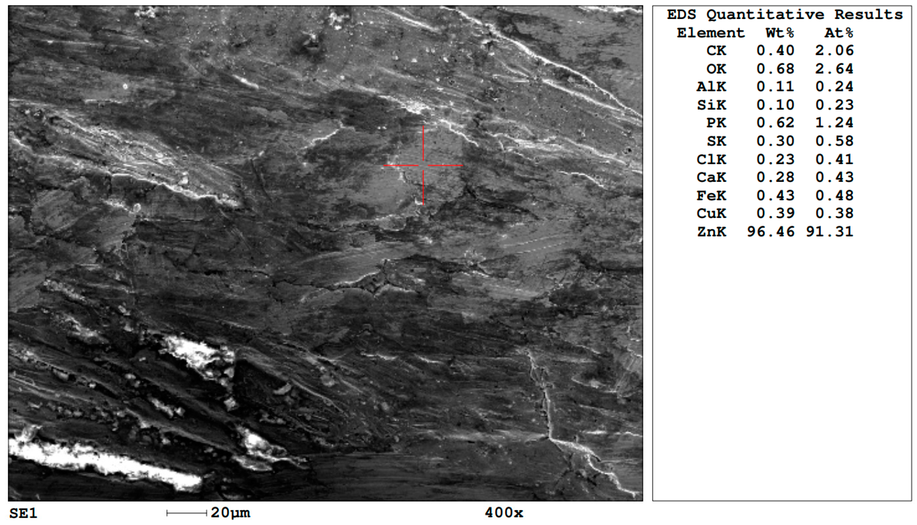
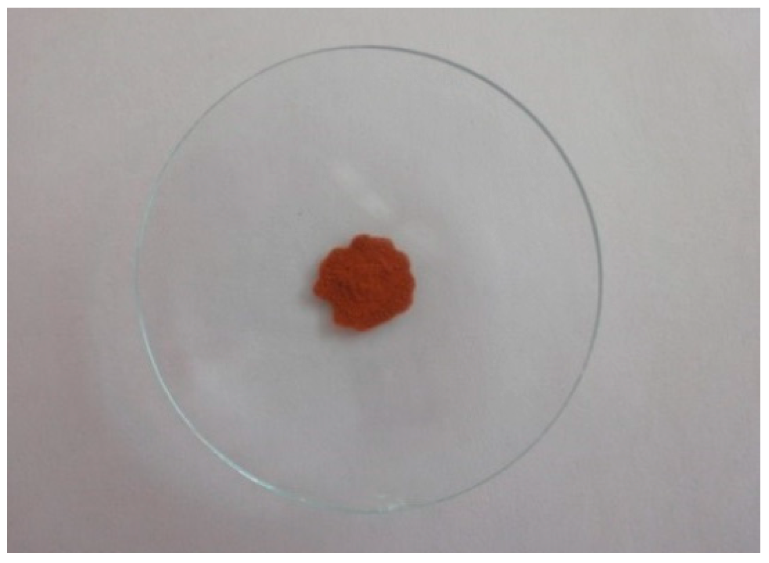
3.2. Assessment of the Impact of Iron-Containing Sediment on Zinc Corrosion

An experiment was carried out to investigate the mechanism of corrosion under the influence of iron sediment. A suspension containing crushed sediment removed from water pipes with traces of corrosion and containing iron oxides and hydroxide (0.45 g of sediment and 2.5 mL of distilled water) was poured into a small sample of galvanized pipe (DN15) that was tightly plugged on one side (Figure 8 and Figure 9). The experiment was held under static conditions at room temperature. The composition of the initial dry iron precipitate, selected during the experiment, was analyzed using a scanning electronic microscope.
During the experiment (within 2 weeks), parts of the sediment were taken from the pipe to determine their composition. Table 3 shows the results of determining the concentration of zinc in the sediment depending on the time of contact with the zinc coating, and Figure 10 reveals the dependence of the zinc content in the sediment on the time of the experiment. The total residence time of the sample with iron-containing sediment was 28 days.
The average zinc content in the sediment increased from 0.81% to 4.07% within two weeks. This confirms the effect of sediment on the rate of zinc corrosion, which is relatively uniform. Meanwhile, in the absence of sediment, the corrosion rate decreased over time (Table 1, tests #3 and #4). Thus, the data obtained indicate a different mechanism of corrosion with oxygen depolarization and contact with iron-containing sediment.
After conducting the experiments, the sample was cut in the longitudinal direction, and an analysis of the condition of the sample surface was made. Figure 11 shows the inner surface of the sample, on which three zones with different colors can be distinguished. The upper zone was the boundary between water and air. The zinc coating above this boundary was not broken. The middle zone had a brown color and was covered with a layer of iron. Since the oxygen concentration in the water was highest in the upper part, it can be concluded that the pipe surface in this zone was a cathode and was also not corroded. The brown color of the surface indicates that an alkaline medium was formed at the cathode, leading to the adsorption of iron hydroxide. The lower zone had a gray color, which is typical for zinc coatings. The acidic environment at the anode contributes to the dissolution of the precipitate and the transition of iron into ionic form.
The transition of zinc into the precipitate occurs according to the reactions presented below. Interacting with Fe3+ iron ions in equilibrium with the precipitate, the zinc coating is destroyed at the anode and passes into water in the form of zinc ions by reaction.
Zn– − Zn2+ + 2e.
Iron (III) ions act as a depolarizer [9], take an electron, and are reduced to Fe (II).
Fe3+ + e = Fe2+
And then iron hydroxide in the form of a precipitate is released at the cathode.
Fe2+ + O2 + H2O = Fe(OH)3.
To determine the thickness of the zinc coating, the longitudinal section of the pipe wall of one part of the cut pipe was subjected to grinding. The measurement was performed using a scanning electron microscope.
The smallest thickness of the zinc layer, equal to 17–19 microns (Figure 12), was found at the boundary where the suspension was divided into water and sediment. This boundary is clearly observed in Figure 11. If the average thickness of the coating is 30 microns, the corrosion rate of the zinc coating can be calculated. Calculations show that the corrosion rate was 0.031 mm/year (or 31 microns/year), which is equal to the coating thickness.
Anions, especially chlorides, play an important role in corrosion reactions. To confirm the mechanism of the effect of chlorides on corrosion, we present the results of a sediment study after three days of contact (Figure 13).
Figure 13 shows a micrograph of the sediment with the results of the determination of the chemical composition. The table in the figure shows that in the sediment (the area highlighted in red), there was a locally increased chloride content of up to 9.72 wt% and zinc of up to 20.11 wt%, while in other randomly selected areas of the same sample, the chloride content did not exceed 1 wt%, and zinc was 2–3 wt%.

4. Conclusions

The presence of zinc-unprotected surfaces on steel pipes, fittings, ball valves, and welded joints, along with a high concentration of oxygen in water, is one of the main reasons for the appearance of intense corrosion of galvanized steel pipes in hot water supply systems. During a short-term experiment, it was found that there is a relationship between the protective ability of the zinc coating and the ratio of the protected and unprotected inner surfaces of the pipe.
The maximum protective effect was obtained at the ratio SZn/SFe = 9:1. If the balance between the protective ability of zinc and the area of the steel base of pipes unprotected by zinc is disturbed, iron accumulates in the circulation circuit. This, in turn, leads to accelerated corrosion of the zinc coating in places of accumulation of iron-containing sediment and the further development of intense corrosion of the base metal of steel pipes.

Author Contributions

Conceptualization, N.M. and V.C.; methodology, N.M. and V.C.; software, N.M. and V.C.; validation, N.M. and V.C.; formal analysis, N.M. and V.C.; investigation, N.M. and V.C.; resources, N.M. and V.C.; data curation, N.M. and V.C.; writing—original draft preparation, V.C.; writing—review and editing, N.M.; visualization, N.M. and V.C.; supervision, N.M. and V.C.; project administration, N.M.; funding acquisition, N.M. All authors have read and agreed to the published version of the manuscript.

Funding

This work was financially supported by the Ministry of Science and Higher Education of Russian Federation (grant # 075-15-2021-686). Tests were carried out using research equipment of the Head Regional Shared Research Facilities of the Moscow State University of Civil Engineering.

Institutional Review Board Statement

Not applicable.

Informed Consent Statement

Not applicable.

Data Availability Statement

Not applicable.

Conflicts of Interest

The authors declare no conflict of interest.

References

  1. Gomatin, N.A. Physical and chemical basis of corrosion of zinc coatings. Int. J. Human. Nat. Sci. 2019, 4, 32–35. [Google Scholar] [CrossRef]
  2. State Standard of Russia Federation. GOST 3262-75; Water-Supply and Gas-Supply Steel Pipes. Spesifications. Available online: https://docs.cntd.ru/document/1200001411 (accessed on 24 August 2023).
  3. State Standard of Russia Federation. GOST 10704-91; Electrically Welded Steel Line-Weld Tubes. Range. Available online: https://docs.cntd.ru/document/1200001409 (accessed on 24 August 2023).
  4. State Standard of Russia Federation. GOST 9.307-2021; Unified System of Corrosion and Ageing Protection. Hot-Dip Zinc Coatings. General Requirements and Methods of Control. Available online: https://docs.cntd.ru/document/1200181658 (accessed on 24 August 2023).
  5. Hilbert, L. Monitoring corrosion rates and localised corrosion in low conductivity water. Corros. Sci. 2006, 48, 3907–3923. [Google Scholar] [CrossRef]
  6. Liu, J.; Shentu, H.; Chen, H.; Ye, P.; Xu, B.; Zhang, Y.; Bastani, H.; Peng, H.; Chen, L.; Zhang, T. Change regularity of water qual-ity parameters in leakage flow conditions and their relationship with iron release. Water Res. 2017, 124, 353–362. [Google Scholar] [CrossRef] [PubMed]
  7. Andrianov, A.P.; Chukhin, V.A. Investigation of the initial stage of pitting corrosion of galvanized pipes in hot water supply systems. Sys. Technol. 2021, 1, 9–14. [Google Scholar]
  8. Chukhin, V.A.; Andrianov, A.P. Analysis of the causes of accelerated corrosion of steel pipelines in hot water supply systems. Sys. Technol. 2021, 1, 66–71. [Google Scholar]
  9. Marjanowski, J.; Ostrowski, J. Electrochemical Protection against Corrosion Processes in Hot Tap Water Installations; C.B.W. Unitex Ltd.: Gdansk, Poland, 2015. [Google Scholar]
  10. Uhlig, H.H.; Revie, R.W. Corrosion and Corrosion Control, 4th ed.; Wiley: Hoboken, NJ, USA, 2008; p. 512. [Google Scholar]
  11. Construction Code of Russian Federation SP 40-108-2004. Design and Installation of Pipelines for Internal Cold, Hot Water Supply and Heating Systems Made of Copper Pipes. Available online: https://docs.cntd.ru/document/1200037605 (accessed on 24 August 2023).
  12. Delaunois, F.; Tosar, F.; Vitry, V. Corrosion behaviour and biocorrosion of galvanized steel water distribution systems. Bioelectrochemistry 2014, 97, 110–119. [Google Scholar] [CrossRef] [PubMed]
  13. Grigoriev, O.; Petukhov, V.; Sokolov, V. Malfunctions of power supply systems of buildings accelerate corrosion of pipelines. News Electrotech. 2003, 2. Available online: http://news.elteh.ru/arh/2003/22/18.php (accessed on 24 August 2023).
  14. Shi, H.; Liu, F.; Han, E.H. The corrosion behavior of zinc-rich paints on steel: Influence of simulated salts deposition in an offshore atmosphere at the steel/paint interface. Surf. Coat. Technol. 2011, 205, 4532–4539. [Google Scholar] [CrossRef]
  15. Shreepathi, S.; Bajaj, P.; Mallik, B.P. Electrochemical impedance spectroscopy investigations of epoxy zinc rich coatings: Role of Zn content on corrosion protection mechanism. Electrochim. Acta 2010, 55, 5129–5134. [Google Scholar] [CrossRef]
  16. Feng, Z.; Frankel, G.S. Galvanic Test Panels for Accelerated Corrosion Testing of Coated Al Alloys: Part 2—Measurement of Galvanic Interaction. Corrosion 2013, 70, 95–106. [Google Scholar] [CrossRef] [PubMed]
  17. Jain, R.; Pitchumani, R. Fabrication and characterization of zinc-based superhydrophobic coatings. Surf. Coat. Technol. 2018, 337, 223–231. [Google Scholar] [CrossRef]
  18. Saeedikhani, M.; Wijesinghe, S.L.; Blackwood, D.J. Moving boundary simulation and mechanistic studies of the electrochemical corrosion protection by a damaged zinc coating. Corros. Sci. 2020, 163, 108296. [Google Scholar] [CrossRef]
  19. Mena, E.; Veleva, L.; Souto, R.M. Early Stages of Zinc Corrosion and Runoff Process Induced by Caribbean Sea Water. Int. J. Electrochem. Sci. 2015, 10, 7596–7605. [Google Scholar] [CrossRef]
  20. Vasyliev, G.S. The influence of flow rate on corrosion of mild steel in hot tap water. Corros. Sci. 2015, 98, 33–39. [Google Scholar] [CrossRef]
Figure 1. Photos of galvanized pipe samples (DN15) before (a) and after (b) exposure to hot water for 4 h.
Applsci 13 10564 g001
Figure 2. Micrograph and chemical composition of sediment on the wall of the pipe not protected by zinc.
Applsci 13 10564 g002
Figure 3. Micrograph and chemical composition of surface layer of the new galvanized pipe DN15.
Applsci 13 10564 g003
Figure 4. Micrographs of the zinc coating throughout various areas (a,b) of the sample after 24 h in hot water.
Applsci 13 10564 g004
Figure 5. Elemental composition of the zinc coating surface layer throughout various areas of the sample after 24 h in hot water (EDS values are shown for area in red square).
Applsci 13 10564 g005aApplsci 13 10564 g005b
Figure 6. Photo of a sample of DN15 galvanized pipe: (a) sample before exposure of hot water; (b) sample after 24 h in hot water; (c) sample (b) with the groove; (d) sample with the groove after 24 h in hot water.
Applsci 13 10564 g006
Figure 7. Micrograph of the chemical composition on the surface of the groove: (1,3) cathode areas of the sample; (2) anode areas of the sample.
Applsci 13 10564 g007
Figure 8. Sample of the galvanized pipe with the iron hydroxide sediment.
Applsci 13 10564 g008
Figure 9. Sample of the sediment.
Applsci 13 10564 g009
Figure 10. Zinc content (obtained values and trend) in the sediment related to the time of exposure.
Applsci 13 10564 g010
Figure 11. Sample surface after exposing to the sediment of Fe(OH)3.
Applsci 13 10564 g011
Figure 12. Thickness of zinc coating after 28 days of contact.
Applsci 13 10564 g012
Figure 13. Chemical composition of the sediment (in the red square area) after 3 days of exposure.
Applsci 13 10564 g013
Table 1. Determination of the corrosion rate of pipe samples in tap water at different temperatures.
Test T (h)M1 (g)M2 (g)ΔM = M1M2 (g)SCR **
(gm−2h−1)
DCR (mm/year)SZn/SFe
tcw = 16 °C
123.713.624813.62240.00240.08270.102-
2 *2454.074054.04900.02500.1740.197-
Thw = 45–47 °C
33.513.621313.61920.00210.4690.576-
42421.929921.91860.01130.2260.2786.30
52421.568821.55320.01560.3460.5223.55
6 *2053.542053.48300.05900.4920.560-
* The values obtained during the corrosion of an uncoated steel pipe sample. The sample area was 60 cm2, the density of iron was 7.874 g/cm3, and the density of zinc was 7.133 g/cm3. ** The values of the corrosion rate given in the table should be taken as indicative of the weight of the sorbed chemical compounds on the cathode areas of the surface of the samples and the amount of iron removed (entered into the tap water) from the anode areas of the disturbed zinc coating.
Table 2. Sediment content.
AreaElement Deposit Content, Wt%/At%
COAlSiPSClCaFeCuZn
19.82/
21.03
25.95/
41.72
0.59/
0.56
0.62/
0.56
0.61/
0.50
0.53/
0.62
0.43/
0.31
37.52/
24.07
20.85/
9.60
0.21/
0.08
2.88/
1.13
24.70/
13.38
17.85/
38.13
0.82/
1.04
0.49/
0.60
0.25/
0.28
0.25/
0.27
0.22/
0.21
0.39/
0.33
73.60/
44.91
0.26/
0.14
1.36/
0.71
33.66/
12.19
9.94/
24.88
0.52/
0.77
0.93/
1.33
0.26/
0.34
0.31/
0.38
0.26/
0.29
0.51/
0.51
77.66/
55.66
0.58/
0.37
5.57/
3.29
Table 3. Zinc content in the sediment depending to time of contact.
Time (d)0 (Initial Sediment)13714
Zinc content, wt%0.811.361.662.024.07
Disclaimer/Publisher’s Note: The statements, opinions and data contained in all publications are solely those of the individual author(s) and contributor(s) and not of MDPI and/or the editor(s). MDPI and/or the editor(s) disclaim responsibility for any injury to people or property resulting from any ideas, methods, instructions or products referred to in the content.

