Article

Evaluating the Time-Dependent Behavior of Deeply Buried Tunnels in Soft Rock Environments and Relevant Measures Guaranteeing Their Long-Term Stability

Department of Hydraulic Engineering, College of Hydraulic and Environmental Engineering, China Three Gorges University, Yichang 443002, China
*
Authors to whom correspondence should be addressed.
Appl. Sci. 2023, 13(18), 10542; https://doi.org/10.3390/app131810542
Submission received: 31 August 2023 / Revised: 17 September 2023 / Accepted: 20 September 2023 / Published: 21 September 2023
(This article belongs to the Special Issue High-Reliability Structures and Materials in Civil Engineering)

Abstract

:
The time-dependent behavior and long-term stability of deep-buried tunnels in soft rocks have received lots of considerations in tunnel engineering and allied sciences. To better explore and deepen the engineering application of rock creep, extensive research studies are still needed, although fruitful outcomes have already been obtained in many related investigations. In this article, the Weilai Tunnel in China’s Guangxi province is studied, taking its host rocks as the main research object. In fact, aiming at forecasting the time-varying deformation of this tunnel, a novel elasto-visco-plastic creep constitutive model with two variants is proposed, by exploiting the typical complex load–unload process of rock excavation. The model is well validated, and good agreements are found with the relevant experimental data. Moreover, the time-dependent deformation rules are properly established for the surrounding rocks, by designing two new closed-form solutions based on the proposed creep model and the Hoek–Brown criterion. To investigate the effects of the major creep parameters and the geological strength index (GSI) of the surrounding rocks on the time-dependent trend of the tunnel, an in-depth parametric study is carried out. It is shown that the convergence deformation of the surrounding rocks is remarkably influenced by the GSI and creep parameters. The convergence deformations calculated from the closed-form solutions conform well to the on-site monitoring data. In only 27 days after excavation, the creep deformation of the Weilai tunnel overtakes 400 mm, which is enormous. To guarantee the long-term stability of this tunnel, a robust support scheme and its long-term monitoring with appropriate remote sensors are strongly suggested.

1. Introduction

Deep-buried tunnels often suffer large deformations that can persist for a long period of time. Indeed, the host rocks of these tunnels usually tend to undergo appreciable time-dependent deformations, and their stability is increasingly affected. The rock mass properties, the rigidity, and the installation time of the support structure are among the major factors governing the displacements in the surrounding rocks of deep tunnels [1,2]. In fact, in deep rocky environments where there are generally durable actions of high stress, abundant groundwater, and fluctuating temperatures, the time-dependent deformation and long-term stability of the host rocks of deep underground tunnels are of increasing concern. This is due to the fact that gradual deformation of the surrounding rocks is inevitable, once deeply buried tunnels are drilled. Owing to the unavoidable creep behavior of loaded rock materials [3,4], the development of microcracks around underground tunnels is imperative [5]. Creep is the time-dependent strength and deformations of rocks [6], and it is linked to the long-term stability of deep rock engineering. The time-dependent behavior of deep soft rock engineering is generally viewed as important, and poses serious stability problems. In the field of tunnel engineering, considerable progress and fruitful results have already been achieved. In spite of that, it is still difficult to guarantee the long-term stability of deep soft rock tunnels, which typically suffer from extreme rheology, and are characterized by significant creep deformations. According to Zhu et al. [7], the consequences of dilatancy-induced high in situ stress and the deformation caused by inadequate support are responsible for the enormous deformation of such tunnels.
The time-dependent behavior and long-term stability of deep rock soft tunnels based on rock creep have been investigated by many scholars and researchers. For example, by studying the key risks related to underground engineering, Yang et al. [8] revealed that inordinate creep is the predominant cause of failure of deep underground storage structures. They explained that a better description and application of creep properties are of utmost importance to avoid failure of the mentioned structures, particularly when they are located in low-strength soft rock environments. On their sides, and by associating volumetric creep and deviatoric behavior, Zeng et al. [9] established a creep constitutive model for porous sandstone. However, their model cannot fully depict the behavior of surrounding rocks of deep tunnels constructed in bedded porous sandstones affected by the presence of water. Based on an improvement of the Burgers model and the empirical-theoretical method, a visco-elastic-plastic creep constitutive model was conceived by Zuo et al. [10] to reflect the time-dependent behavior and stability of deep soft rock tunnels mainly built in soft schist media. Liu et al. [11] studied the creep behavior of deep sandstones, and employed fractional derivatives to design two nonlinear creep models that take into account viscoelasticity and time-dependent damage. However, the engineering applications of these models are not detailed. To combat the large deformation, and ensure the stability of deep tunnels located in broken soft rock layers, Deng et al. [12] designed a creep model by taking the Burger Constitutive Viscoplastic (Burger model jointed to the Mohr–Coulomb body) model as a basis. They then analysed the possibility of optimizing the support scheme for these tunnels. A viscoelastic-plastic creep model was developed by Feng [13] to forecast time-dependent deformations of deep soft rock roadways mainly lodged in mudstone. For their part, Quevedo et al. [14] studied the long-term stability of deep tunnels using both the creep constitutive model of the surrounding rocks and that of the support, and emphasizing the long-lasting impact of creep on the support structure. Lately, by employing fractional differential order, Yang et al. [15] proposed a workable creep constitutive model to predict the time-dependent evolution of deep soft rocks. However, their model is suited to deep hydropower stations located in dry states. Despite many abundant research results, in-depth studies on the long-term stability of deep soft rock tunnels are still needed. It should be highlighted that engineering situations vary from case to case. Ongoing research studies are thus required in order to continually improve and deepen the precise application of rock creep in tunnel engineering.
This paper aims to thoroughly study the time-dependent behavior of deep-buried tunnels located in soft rocky media. Owing to its complex geological and hydrological conditions, the Weilai Tunnel in China’s Guangxi province is taken as the main research background. Such a tunnel can fill the research gaps to a sufficient extent, because not only are its host rocks soft and weakened, groundwater inflows are common there. In this tunnel, the main features of deep rock engineering are represented. Indeed, a novel creep constitutive model with two variants is developed, and its adequate conversion into two new analytical solutions is widely demonstrated. Appropriate parametric investigations are carried out to show the rationality of the closed-form solutions. Then, the tunnel convergence deformations are calculated and verified with on-site monitoring data. The significance of this research study is considerable for an in-depth understanding of rock creep application in tunnel engineering. Accordingly, related research studies may well use this article as a very good reference.

2. Study Area and Engineering Situation

The Weilai Tunnel is located in Weilai Village, Bada Town, Xilin County, in China’s Guangxi Province. It is a component of the Tianxi Expressway project and belongs to the National Highway G357. The projected tunnel is a two-lane separation tunnel. The right line has a length of 662 m, and its starting and ending stakes are marked K114 + 422~K115 + 084. The left line has a length of 686 m, and its starting and ending stakes are denoted Z4K114 + 424~Z4K115 + 110. In conformity with the engineering reports, the maximum burial depth of the tunnel is 105 m. Figure 1 provides a location map of the Weilai Tunnel.

2.1. Geology and Hydrology of the Tunnel Site

The geological environment of the Weilai Tunnel is complex. The tunnel site originates from the structural unit of the Xilin-Baise fault belt in the Youjiang regeneration trough of the Nanhua quasi-platform. Evident structural developments and large-scale sedimentary depressions are encountered in the tunnel site. Huge mountains, intersecting ridges, and valleys surround the tunnel site. Quaternary residual slope accumulation characterizes the site, and is mainly composed of argillaceous sandstone, sandstone, and mudstone. Nevertheless, argillaceous sandstone is the most predominant rock type in the tunnel alignment. The main lithology encountered along the tunnel route is schematized in Figure 2.
Groundwater inflows into the tunnel are mainly facilitated by the unfavorable geological conditions of the surrounding rocks, and the availability of groundwater in the existing aquifers. In fact, it should be noted that karst terrains exist in a relatively large scale in Guangxi province, which is located on the southeastern edge of the Yunnan-Guizhou Plateau. Typically, nearly 50% of groundwater inflows into rock tunnels are facilitated by karst terrains [16,17]. The risk level of tunnel construction in Guangxi is increased by the ingress of groundwater into the host rocks.

2.2. Excavation Method and Characteristics of the Surrounding Rocks

Owing to the complexity of the tunnel site, the drill-and-blast excavation method was utilized. Since the main rock type encountered in the tunnel alignment is broken and weakened, the blasting and the vibration velocity were scrupulously controlled. Throughout the entire line of the tunnel, based on a geological survey, the surroundings rocks are mainly categorized as class IV (soft rocks) and class V (broken soft rocks). Figure 3 illustrates the excavated tunnel subjected to a virgin in situ stress P 0 , and a view of the tunnel portal.
Any excavation method provokes increased damage to the surrounding rocks of deep-buried tunnels. Nevertheless, drill-and-blast excavation has the reputation for causing significant damage to the rocks hosting the tunnels [18]. In fact, such an excavation method is typically characterized by a large unloading rate and short unloading time [19,20,21], and therefore considerably affects the relevant properties of the host rocks. Based on relevant research outcomes [13,22,23,24], the average basic values of the physical-mechanical parameters of the host rocks are presented in Table 1 in dry states.
It is important to relate that the rock parameters are affected by the presence of groundwater in the regional environment of the tunnel. As already explained, due to the hydrological conditions of the tunnel site, groundwater effects cannot be neglected. Indeed, most rock parameters are diminished due to the effects of water [25]. Under wet conditions, uniaxial compressive strength, elastic modulus, internal friction, and cohesion are generally reduced, while density and Poisson’s ratio can be enhanced [26]. For wet conditions, the average values adopted for the physical-mechanical parameters of the host rocks are presented in Table 2.

3. Novel Creep Constitutive Model for the Host Rocks of the Weilai Tunnel

Conceiving the most appropriate constitutive relationship, and being able to correctly reflect the comportment of the host rocks, is a major task for addressing the long-term stability of deeply buried tunnels. To this end, mechanical models which are based on a rheological approach are largely utilized. Basically, springs, dashpots, and frictional-cohesive elements are constituents of a given mechanical model [4,27,28]. A novel visco-elastic-plastic creep model that can be well exploited to study the long-term stability of the Weilai Tunnel is of primary consideration. In fact, elasticity, plasticity, viscoelasticity, and viscoplasticity coexist around the rheological deformation of rocks [29]. It is of tremendous importance to take into consideration such rock features in the design of a novel creep constitutive.

3.1. Adopted Creep Tests Data of Sandstone

Adequate typical experimental data from triaxial creep tests under loading–unloading cycles for standard sandstone samples are selected. The selection was mainly based on the following criteria: similar soft rock type, similar soft rock quality, and similar soft rock conditions at great depth, and creep tests on deep sandstone under cyclic load–unload. After carefully identifying and analysing data from several creep tests of the represented rock types of the Weilai Tunnel, the creep test data of Yang et al. [30] were finally selected for their suitability to the initial criteria. It is worth mentioning that other creep test data could also be selected. However, the analysis was rigorously carried out, and the adopted creep test data fully met the criteria. A typical servo-controlled mechanical triaxial test system (RLW-2000) was used in these creep tests. Performed by Yang et al. [30], the mentioned creep tests on deep sandstones reflect the conditions of the environment of the studied tunnel. Confining pressures (4 MPa, 8 MPa, and 12 MPa) were applied on the specimens, which are subjected to load–unload cycles. Table 3 displays the different stress levels adopted for the deviatoric stress during the aforesaid tests.
Note that four traditional creep stages are generally manifested in soft rocks: instant elastic creep, primary creep, steady creep, and tertiary creep phases [28]. Figure 4 illustrates the staged load–unload of sandstone samples under a confining pressure of 4 MPa. Room temperature (25 °C) was considered during the experiments.

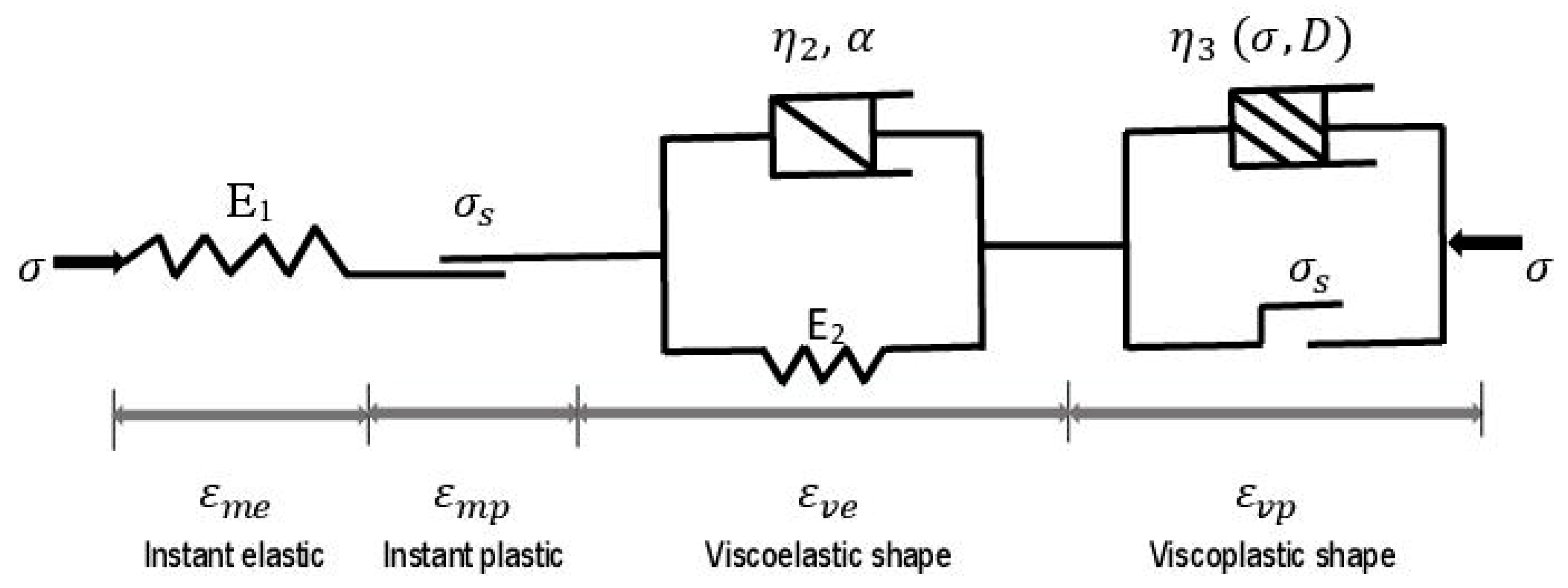
3.2. Governing Equations and Proposed Mechanical Model

It is widely recognized that tunnelling can be characterized by a complex cyclic load–unload [31,32,33]. Rock creep is therefore manifested in both loading and unloading stages, as illustrated in Figure 5. In such situation, the total creep strain can be written as below:
ε = ε m + ε v = ε m e + ε m p + ε v e + ε v p
Here ε stands for the total creep strain; ε m denotes the instant strain; ε v represents the creep strain; ε m e is the instantaneous elastic strain; ε m p denotes the instant plastic strain; ε v e is the visco-elastic strain; and ε v p represents the visco-plastic strain.
As previously mentioned, the complex load–unload process during tunnelling, and the coexistence of elasticity, plasticity, viscoelasticity, and viscoplasticity in rock rheological deformation can be exploited, as the mechanical diagram of the proposed model shows in Figure 6.
As shown in Figure 6, Hooke element, St. Venant, nonlinear Kelvin, and visco-plastic element are the four components of the proposed creep model. This novel model has a great capacity for capturing the creep behavior of the surrounding rocks of the Weilai Tunnel. It constitutes the first variant of the model where dry states are considered. In fact, the instant elastic stage occurs immediately due to the rock excavation effects. The instant plastic stage also occurs at certain stress levels. It traduces the transition between the instant elastic stage and the viscoelastic stage. The viscoelastic stage represents the viscous behavior of the elastic stage under continued constant load, which is inevitable after rock excavation. The viscoplastic stage, which is inevitable under sustained stresses, reflects the unstable creep that occurs after that the rock long-term strength is exceeded by the applied stress. Hence, the model can well represent the cyclic load–unload process of rock excavation.

3.3. Development of the Proposed Creep Constitutive Model

To simulate the instant elastic strain, the Hooke element is taken into account. Thereby, the axial instantaneous elastic strain can be read as follows [32,34]:
ε m e = σ E 1
Here the applied stress is represented by σ , and the elastic modulus by E 1 .
Regarding the axial instant plastic strain, referring to Sterpi and Gioda [35], it can be formulated by considering the modulus of the plastic deformation of the St. Venant element, E p , and the scalar function, I ( σ 1 σ 3 σ s ) , as follows:
ε m p = σ σ s E p   I ( σ σ s )
The scalar function is defined as below:
I σ σ s =   0 ,   σ < σ s   1 ,   σ σ s
Here σ s represents the long-term strength of rocks. Note that the long-term strength of rocks is of particular importance. In fact, due to aging and fatigue, rock strength diminishes with the passage of time [36]. In general, the instant rock strength is typically greater than the long-term strength. For soft rocks, the long-term strength ranges from 70 to 80% of the instant value [36,37].
Concerning the visco-elastic element, it can be simulated by the nonlinear Kelvin shape [38]. Assuming a constant α (material constant) can well reflect the inevitable influence of the stress level on rock creep, and the nonlinear variant of the Kelvin model can be written in its differential constitutive equations as follows:
σ = E 2 ε v e + η 2 t ( 1 α ) ε ˙ v e
Here σ is the applied stress, E 2 stands for the elastic modulus of the Kelvin shape, η 2 represents viscous coefficient of the Kelvin shape, and t is the creep time. The integration of the previous equation can lead to the following:
ε v e = σ E 2 1 e x p E 2 η 2 α t α
For the viscoplastic body, it can be described by improving the Ramberg–Osgood equation. Indeed, to improve the Ramberg–Osgood equation [39], in particular its plastic component, one considers the basic definition of rock creep where strain evolves with time, and under constant stress. Thereby, the visco-plastic creep strain model of soft rock can be written as follows:
ε v p = k σ t η 3 ( t ) n
where k and n represent constants related to rock materials; σ denotes the applied stress; t is creep time; and η 3 stands for coefficient of the initial viscosity of the viscoplastic body.
The variable damage ( D ) is introduced, since it is of primary consideration at this stage. It should be noted that, under sustained effects of deviatoric stress, the evolution of damage in rock materials is unavoidable, and one of the parameters which is affected by damage is the viscosity coefficient. Hence, the damaged viscosity coefficient can be expressed as below:
η 3 ( t ) = η 3 ( 1 D )
Combining Equations (7) and (8), the visco-plastic creep strain can be expressed as follows:
ε v p = k σ t η 3 n 1 D ( 1 n )
At the tertiary creep stage, as related by [40,41], the evolution of damage in rock materials can be widely expressed as follows:
D d t = A   σ 1 D n
Here A and n are constants related to the materials. Under the evolution of time, critical or full-scope damage generally cause rock failure. Therefore, it is important to take into account the time-to-failure.
By solving Equation (10), and by considering that t = t f , where t f represents the rock time-to-failure, we can obtain the following:
( 1 D ) n + 1 = 1 A σ n 1 + n t t f = 1 A ( 1 + n ) σ n
Afterwards, the combination of Equations (10) and (11) leads to the expression of the damage variable as below:
D = 1 1 t t f 1 1 n
Combining Equations (9) and (12), the visco-plastic creep strain can be expressed as follows:
ε v p = k σ t η 3 n 1 1 1 t t f 1 1 n ( 1 n )
In its one-dimension form, the novel creep model can be written as:
ε   t = σ E 1 + σ E 2 1 e x p E 2 η 2 α t α σ < σ s
ε   t = σ E 1 + σ σ s E p + σ E 2 1 e x p E 2 η 2 α t α + k σ t η 3 n 1 1 1 t t f 1 1 n ( 1 n ) σ σ s
The three-dimensional form of the proposed creep model can be built by considering that rocks are typically in three-dimensional stress states. One assumes that creep is mainly provoked by the deviatoric stress tensor ( S i j ), damage is accounted at the tertiary creep phase, and the Poisson’s ratio of the rocks is not affected by time. The stress tensor ( σ i j ) is mainly composed of the deviatoric stress tensor ( S i j ) and the spherical tensor ( σ m ).
On the basis of Hooke’s law, the deviatoric stress tensor ( S i j ) and the spherical stress tensor ( σ m ) can be expressed as follows:
S i j = σ i j ε m δ i j σ m = 1 3 ( σ 1 + σ 2 + σ 3 )
The shear or deviatoric strain tensor ( e i j ), and the volumetric or spherical strain invariant ( ε m ) are expressed as follows, where δ i j stands for the Kronecker function:
e i j = ε i j ε m δ i j ε m = 1 3 ( ε 1 + ε 2 + ε 3 )
The total strain ( ε i j ) in three-dimensional form can be given by superimposing its components, by assuming that rocks are continuous media, as follows:
ε i j = ε i j m e + ε i j m p + ε i j v e + ε i j v p
where ε i j m e and ε i j v e represent, respectively, the three-dimensional form of the instant elastic strain and the visco-elastic strain; and ε i j m p and ε i j v p are, respectively, the three-dimensional form of the instant plastic strain and visco-plastic strain.
The instant elastic strain ( ε i j m e ) and the visco-elastic strain ( ε i j v e ) can be three-dimensionally expressed as follows:
ε i j m e = 1 2 G 1 S i j ε i j v e = 1 2 G 2 1 e x p G 2 η 2 α t α S i j
Here G 1 is the shear modulus of the elastic element; S i j represents the tensor of stress; G p is the instant shear modulus; and   S s is the long-term strength of rock in three-dimensional form.
Likewise, the instant plastic strain ( ε i j m p ) and visco-plastic strain ( ε i j v p ) can be three-dimensionally written as follows:
ε i j m p = S i j     S s G p ε i j v p = ε i j v p = k S i j t η 3 n 1 1 1 t t f 1 1 n ( 1 n )
The three-dimensional form of the proposed model can thus be read as below:
ε i j = 1 2 G 1 S i j + 1 2 G 2 1 e x p G 2 η 2 α t α S i j   ( S i j < S s ) 1 2 G 1 S i j + S i j     S s G p + 1 2 G 2 1 e x p G 2 η 2 α t α S i j + k S i j t η 3 n 1 1 1 t t f 1 1 n ( 1 n )   ( S i j S s )
with the variable damage D, the three-dimensional form of the proposed model can also be written as follows:
ε i j = 1 2 G 1 S i j + 1 2 G 2 1 e x p G 2 η 2 α t α S i j   ( S i j < S s ) 1 2 G 1 S i j + S i j     S s G p + 1 2 G 2 1 e x p G 2 η 2 α t α S i j + k S i j t η 3 n 1 D ( 1 n )   ( S i j S s )
The axial stress deviator ( S 11 ), for the maximum stress direction, is given by:
S 11 = σ 1 σ m = 2 3 ( σ 1 σ 3 )
Thereby, in the maximum stress direction, the creep model can be computed as:
ε 11 ( t ) = σ 1 σ 3 3 G 1 + σ 1 σ 3 3 G 2 1 e x p G 2 η 2 α t α   ( S i j < S s ) σ 1 σ 3 3 G 1 + 2 ( σ 1 σ 3 )   3 σ s 3 G p + σ 1 σ 3 3 G 2 1 e x p G 2 η 2 α t α + 2 k 3 ( σ 1 σ 3 ) t η 3 n 1 1 1 t t f 1 1 n ( 1 n )   ( S i j S s )  
The unloading of the applied stress is assumed to happen at time t 0 . As such, the three-dimensional form of the proposed creep model can be converted into the following unloading equations:
ε 11 t = σ 1 σ 3 3 G 2 1 e x p G 2 η 2 α t 0 α e x p G 2 η 2 t 0 1 α t 0 t

3.3.1. Identification of Model Parameters

Designed to depict the creep behavior of soft rocks, the novel creep model takes into account several parameters such as elastic, plastic, and viscous. The shear modulus G 1 can be assessed as below:
G 1 = E 2 ( 1 + ν )
where ν denotes poisson’s ratio; and E elastic modulus.
To evaluate G p , the experimental data related to instant plastic creep strains are employed. Concerning the determination of G 2 and α , Equation (32) is used. Note that, under the conditions where time t is infinitely large, and σ < σ s , the aforesaid equations can be modified as follows:
ε = σ 1 σ 3 3 G 1 + σ 1 σ 3 3 G 2
Under the aforementioned conditions, adequate operations are utilized. By denoting by “h”, the subtraction of Equation (24) into Equation (27), we can have the following:
h = E q u a t i o n   ( 24 )     E q u a t i o n   ( 27 ) h = σ 1 σ 3 3 G 2   e x p G 2 η 2 α t α
Additionally, when σ < σ s and t , noting by “J” the natural logarithm of “h” in Equation (28), we can write:
J = l n   ( E q u a t i o n   ( 24 )     E q u a t i o n ( 27 ) J = ln σ 1 σ 3 3 G 2 e x p G 2 η 2 α t α
Equation (29) is a function in which t is the variable. It can be formulated as below:
f t = l n σ 1 σ 3 3 G 2 G 2 η 2 α t α
A nonlinear function can describe the previous function. The general form is as follows:
f t = q + m t k
Here m , k , and q are fitting parameters.
By identifying common terms in Equations (30) and (31), we can obtain:
m = G 2 η 2 α α = k q = l n σ 1 σ 3 3 G 2
The fitting parameters can be used to evaluate G 2 , η 2 , and α . As such, G 2 , η 2 , and α can be found to be:
G 2 = σ 1 σ 3 3 e q α = k η 2 = σ 1 σ 3 3 m k e q
The nonlinear least square method of Levenberg–Marquardt [42] is utilized to determine the viscosity coefficients η 2 and η 3   , and the constant of rock materials n ,. For the fitting of creep test data, a typical parametric equation can be employed as below:
ε = A + B + C 1 e D t + E 1 1 t t f F G
Here ε stands for the total creep strain of the designed model; the fitting parameters are A , B ,   C ,   D ,   E , and F , which are written as follows:
A = σ 1 σ 3 3 G 1 B = 2 ( σ 1 σ 3 )   3 σ s 3 G p C = σ 1 σ 3 3 G 2 D = G 2 η 2 α E = 2 k 3 ( σ 1 σ 3 ) t η 3 n F = 1 1 n G = 1 n
Equations (34) and (35) can be combined as follows:
ε 11 ( t ) = A + C 1 e x p D t α   ( σ < σ s ) A + B + C 1 e x p D t α + E 1 1 t t f F G   ( σ σ s )

3.3.2. Validation of the Proposed Model

The model is verified in good agreement with the results of creep tests under triaxial cyclic load–unload cycles. The coefficient of determination ( R 2 ) is employed to check the model accuracy. Broadly speaking, the peak value of R 2 is 1. Higher values of R 2 correspond to higher accuracies. The coefficient of determination ( R 2 ) is expressed as:
R 2 = 1 i = 1 n y c y i 2 i = 1 n y c y i ¯ 2
Here n represents the amount of test data points; y c stands for calculated values; and y i , and y i ¯ denote, respectively, the test value and its average.
In Table 4 and Table 5, for loading and unloading conditions, the calculated parameters of the model are presented, respectively.
In order to ensure proper validation, comparisons are made between creep strains calculated from the model and the pertinent experimental data. The results under different levels of the deviatoric stress are displayed in Figure 7, Figure 8, Figure 9, Figure 10 and Figure 11.
As displayed in Figure 7, Figure 8, Figure 9, Figure 10 and Figure 11, both in the loading stage and in the unloading stage, the model is in good agreement with the experimental data. The proposed model can thus well simulate the creep behavior of the studied tunnel. It can be remarked that there is a huge difference between the values obtained from the loading stage and those obtained from the unloading stage. In fact, the unloading process has considerable effects on the mechanical properties of soft rocks. Since cracks generally tend to evolve rapidly in unloaded rocks, the relevant rock mechanical properties are affected by the unloading phase, and then altered to some extent. It should be noted that, generally, soft rocks have lesser abilities to withstand deformations generated by the unloading stage than those caused by the loading stage. This is why rock rupture can be faster during the unloading process than during the loading process. Thereby, when studying the long-term safety and stability of deeply buried tunnels, the cyclic loading–unloading process of the host rocks plays a key role.
There is a rapid evolution of the creep process of sandstone under the deviatoric stress of 23.98 MPa, as revealed in Figure 11. As the stress level is high, there is a rapid appearance of tertiary creep. In fact, high deviatoric stress is capable of shortening the duration of steady creep, and hastening the triggering of tertiary creep. At a high stress level, the rapid onset of tertiary creep will seriously jeopardize the long-term stability of the tunnel. Appropriate measures are quickly needed to ensure the longest duration of steady creep in deep rock tunnels subject to high geostresses.
Aiming at expanding the validation of the proposed model, one analyses the effects of rock damage on viscoplastic strain. The variation of rock damage is also investigated. Here, the viscoplastic stage which represents the tertiary creep stage, is selected for that, as it is new with respect to the more familiar models (nonlinear Kelvin, St. Venant, and Hooke). It is well known that the damage variable in rock varies from 0 to 1. The nondamaged or intact rocks have a damage index of 0, while the damage index of the extremely damaged rocks is 1. To better perform our analysis and facilitate understanding, the variable damage (D) of Equation (22) can be represented by a damage index δ . At the viscoplastic or tertiary creep stage, the rock is indisputably damaged. Four values (0.2; 0.4; 0.6; 0.8) of the damage index are taken into account in the analysis. The variation of model viscoplastic strain considering different damage index values is shown in Figure 12. The rock damage law is also presented in Figure 13. Succinctly, Figure 12 and Figure 13 reveal the significance of rock damage effects in the proposed creep constitutive model (first variant). They clearly illustrate the effects of damage in the evolution of rock creep, and therefore expand the understanding of the proposed model.

3.3.3. Effect of Pore Water Pressure: Second Variant of the Proposed Model

The influence of pore water pressure cannot be overlooked, since the predominant rock type of the studied tunnel is broken, and groundwater is abundant in the concerned media. Seepage actions can be severe in this rocky environment. They can generally reduce the bearing capacity of the support structure by modifying the stress allotments around the overall tunnel components [43]. Thereby, it is of tremendous importance to take into account the influence of pore water pressure on the creep process. To this end, damage is particularly accounted for in tertiary creep. It is well known that damage augments as the tertiary creep stage evolves. Therefore, in order to account for the effects of pore water pressure on rock creep, the damage variable is employed. In this situation, the damage variable can be read as below, where β   ( σ ,   p ) is a material constant which is affected by pore water pressure ( p ) and stress ( σ ):
D = 1 e β   ( σ ,   p ) t
A variant of the mechanical model which is affected by pore water pressure is presented in Figure 14.
The jointed influence of pore water pressure and confining pressure is taken into account. This influence can be written, for the visco-plastic element, as follows:
η 3   σ   ,   p ,   D = η 3   σ   ,   p ( 1 D )
Equations (22), (38) and (39) are adequately combined. The three-dimensional form of the novel creep model with effects of pore water pressure can be written as:
ε i j   ( t ,   σ ,   p ) = 1 2 G 1   ( σ ,   p ) S i j + 1 2 G 2   ( σ ,   p ) 1 e x p G 2   ( σ ,   p ) η 2   σ ,   p α t α S i j   ( S i j < S s ) 1 2 G 1   ( σ ,   p ) S i j + S i j     S s G p   ( σ ,   p ) + 1 2 G 2   ( σ ,   p ) 1 e x p G 2   ( σ ,   p ) η 2   ( σ ,   p ) α t α S i j + k S i j t η 3   ( σ ,   p ) n e β   ( σ ,   p ) t ( 1 n )   ( S i j S s )
For the maximum stress direction, the model affected by pore pressure can be read as follows:
ε 11 ( t ,   σ ,   p ) = σ 1 σ 3 3 G 1   ( σ ,   p ) + σ 1 σ 3 3 G 2 ( σ ,   p ) 1 e x p G 2   ( σ ,   p ) η 2   ( σ ,   p ) α t α   ( σ < σ s ) σ 1 σ 3 3 G 1 ( σ ,   p ) + 2 ( σ 1 σ 3 )   3 σ s 3 G p   ( σ ,   p ) + σ 1 σ 3 3 G 2   ( σ ,   p ) 1 e x p G 2   ( σ ,   p ) η 2   σ ,   p α t α + 2 k 3 ( σ 1 σ 3 ) t η 3   ( σ ,   p ) n e β   ( σ ,   p ) t ( 1 n )   ( σ σ s )
Taking into consideration the variation trend in the mechanical properties of the soft rocks subjected to pore water pressure change [44], the parameters of the model are scrupulously evaluated for three levels (0.05 MPa, 0.10 MPa, 0.15 MPa) of pore water pressure. Table 6 and Table 7 show the parameters.
Under loading and unloading conditions, Figure 15, Figure 16 and Figure 17 present the effects of pore water pressure on the evolution of rock creep.
Figure 15, Figure 16 and Figure 17 clearly reveal that pore water pressure seriously affects the creep process of the rocks surrounding the studied tunnel. The creep strain increases, and the creep life of the rock decreases when pore water pressure increases. In fact, the higher the pore pressure, the faster the creep process evolves. Pore water pressure shortens the duration of both loading and unloading processes. It is one of the major factors causing considerable instability in deep rock engineering. It can even provoke unexpected failure of deep soft rocks subjected to elevated stress, as can be interpreted in Figure 17.
Figure 17 shows that, even under low pore water pressure, with the effects of pore water pressure, the creep of sandstone develops more rapidly than in dry conditions. Indeed, with the influence of pore water pressure, the tertiary creep triggers earlier, after only 40 h. However, in dry conditions, tertiary creep happens after nearly 60 h. In the context of long-term stability of the deep soft rock tunnel, the effects of the pore water pressure must be strongly addressed.
Similar to the dry states, considering different damage index values, the evolution of the viscoplastic strain of the host rocks in wet conditions ( p = 0.10   M P a ) and the damage variable are examined, and the results are displayed in Figure 18 and Figure 19. This also gives an expansion on the understanding of the model (second variant). Figure 18 and Figure 19 reveal the significance of rock damage effects in the proposed creep constitutive model.

4. Closed-Form Solutions and Convergence Deformation of the Weilai Tunnel

Reliable closed-form solutions are necessary to assess the time-dependent deformation of deep-buried tunnels, particularly those built in complex rocky media. The proposed creep constitutive with its two variants has to be converted into two closed-form solutions. To do this, a suitable tunnel mechanical model is adopted. As shown in Figure 20, the tunnel is subjected to a virgin in situ stress field ( P 0 ). It is assimilated to a circular tunnel where the radius is R 0 . The rocks surrounding the tunnel deform elastically, viscoelastically, plastically, and viscoplastically. The distance between the center of the tunnel and the limit of the viscoplastic zone is denoted by R P . The actual cross section geometry has two parts, which comprise a semi-circular part (the upper part) and a rectangular part (the lower part). For calculation and analysis convenience, and referring to Peng et al. [45], it is assumed that a circular section can represent the two sections.
In the postexcavation phase, the actual state of the tunnel can be described by two main zones, namely, the internal and the external zones. The visco-plastic conditions are depicted by the internal zones, and the visco-elastic states by the external zones. Typically, the nonlinear failure characteristics of rocks can be described by the Hoek–Brown criterion, where the concerned elastic and plastic parameters can be defined. Thereby, parameters in the elastic and plastic zones can be, respectively, given as follows [46,47,48]:
σ r e = P 0 R 0 2 r 2 N 1 e 2 M σ θ e = P 0 + R 0 2 r 2 N 1 e 2 M σ z e = P 0 M = m 2 + 16 m P 0 σ c + 16 s 4 s m 2 m N 1 = P 0 M σ c s M 2 m σ c 4
σ r p = m σ c 4 l n r R 0 2 + σ c s l n r R 0 σ θ p = m σ c 4 l n r R 0 2 + ( m σ c 2 + σ c s ) l n r R 0 + σ c s σ z p = 1 + sin θ σ θ p + ( 1 s i n θ ) σ r p 2 R P = R 0 e M
Here the radial elastic stress, axial elastic stress, and hoop elastic stress are, respectively, noted by σ r e , σ z e , and σ θ e . For intact rocks, the unconfined compressive strength is represented by σ c . Likewise, the radial plastic stress, axial plastic stress, and hoop plastic stress are, respectively, noted by σ r p , σ z p , and σ θ p . The distance related to the central point of the section of the tunnel is noted by r . The dilation angle is indicated by ϕ , and is given by:
ϕ = 5 G S I 125 1000 φ
Here G S I is geological strength index, and φ denotes internal friction angle of the rock. The material parameters are m b and s , and can be determined as follows:
m b = m i exp G S I 100 28 14 D s = exp G S I 100 9 3 D
where m i stands for strength constant for geomaterials, and D represents a parameter related to the degree of rock mass perturbation. As already mentioned, D [ 0 ,   1 ] where 0 traduces undisturbed rock mass, and 1 is wholly disturbed rock mass.
The strain and displacement are correlated. In the visco-elastic zone, this correlation can be given as below:
ε θ = u r ε r = d u d r
Additionally, we can write:
σ 1 = σ θ σ 3 = σ r
By replacing Equation (42) into Equation (22), and by overlooking the viscoplastic part, and by taking into consideration Equations (46) and (47), the viscoelastic deformation of the host rocks can written as:
u r v e = 2 R 0 2 N 1 e 2 M 3 G 1 r + 2 R 0 2 N 1 e 2 M 3 G 2 r 1 e x p G 2 η 2 α t α
Here u r v e represents the creep deformation of the viscoelastic zone.
Concerning the visco-plastic zones of the tunnel, a nonassociated plastic flow law is considered, since the dilation undoubtedly occurs in the plastic zone. As stated by Manh et al. [49], viscoplastic strains and displacements can be therefore linked as below:
d u r v p d r + k ϕ u r v p r = ε r + k ϕ ε θ
Here the visco-plastic deformation of the surrounding rocks of a tunnel is noted by u r v p ; ε r is radial strain; ε θ is hoop strain; the coefficient of dilation is indicated by k ϕ , and can be given as follows:
k ϕ = 1 + s i n ϕ 1 s i n ϕ
A combination of Equations (22), (43), (47) and (49) leads to the following:
d u r v p d r + k ϕ u r v p r = 1 3 G 1 + 1 G p + 1 3 G 2 1 e x p G 2 η 2 α t α + k t η 3 n 1 D ( 1 n ) S r p + k ϕ S θ p 1 + k ϕ S s G p
The three-dimensional forms of σ r p and σ θ p , which are, respectively, S r p and S θ p , can be written as follows:
S r p = ( 3 + s i n φ ) 12 m σ c l n r R 0 ( 3 + s i n φ ) 6 σ c s S θ p = ( 3 s i n φ ) 12 m σ c l n r R 0 + ( 3 s i n φ ) 6 σ c s
From Equation (51), a function g t can be defined as below:
g t = 1 3 G 1 + 1 G p + 1 3 G 2 1 e x p G 2 η 2 α t α + k t η 3 n 1 D ( 1 n )
There is compatibility of deformations at the existing interface between the visco-plastic and visco-elastic zones. This condition is taken into account to evaluate the global visco-plastic deformation of the host rocks. At the aforesaid interface, this condition can be written as follows:
r = R P u r v p R P ,   t = u r v e ( R P ,   t )
Subsequently, we can have the following:
u r v p R P ,   t = u r v e R P ,   t = 2 R 0 2 N 1 e 2 M 3 G 1 R P + 2 R 0 2 N 1 e 2 M 3 G 2 R P 1 e x p G 2 η 2 α t α
The global visco-plastic deformation of the surrounding rocks (dry states) of the tunnel is assessed by combining Equations (51) and (55). Its expression is given by:
u r v p ( t ) = m σ c 12 g t k ϕ 3 s i n ϕ ( 3 + s i n ϕ ) g 1 r + σ c s 6 g t k ϕ 3 s i n ϕ ( 3 + s i n ϕ ) g 2 r + 1 + k ϕ S s G p g 2 r + 2 R 0 2 N 1 e 2 M 3 G 1 R P + 2 R 0 2 N 1 e 2 M 3 G 2 R P 1 e x p G 2 η 2 α t α g 3 r
The subfunctions g 1 r , g 2 r , and g 3 r are defined as follows:
g 1 r = r k ϕ + 1 l n r R 0 R P k ϕ + 1 R P r k ϕ l n R P R 0 r R P R P r k ϕ 1 + k ϕ 2 g 2 r = r R P R P r k ϕ 1 + k ϕ g 3 r = R P r k ϕ
For the second variant, which takes into account the effects of the pore water pressure, closed-form solutions are also conceived. Following the same steps as above, the global viscoplastic deformation of the tunnel, under the influence of pore water pressure, can be computed as:
u r v p ( t ,   σ ,   p ) = m σ c 12 h t k ϕ 3 s i n ϕ ( 3 + s i n ϕ ) g 1 r + σ c s 6 g t k ϕ 3 s i n ϕ ( 3 + s i n ϕ ) g 2 r + 1 + k ϕ S s G p g 2 r + 2 R 0 2 N 1 e 2 M 3 G 1 R P + 2 R 0 2 N 1 e 2 M 3 G 2 R P 1 e x p G 2 η 2 α t α g 3 r
The influence of pore water pressure is taken into consideration by the function h t , which is defined as follows:
h t = 1 2 G 1   ( σ ,   p ) + 1 G p   ( σ ,   p ) + 1 2 G 2   ( σ ,   p ) 1 e x p G 2   ( σ ,   p ) η 2   ( σ ,   p ) α t α + k t η 3   ( σ ,   p ) n e β   ( σ ,   p ) t ( 1 n )
The subfunctions g 1 r , g 2 r , and g 3 r are previously defined in Equation (57).

4.1. Sensibility Analysis

The relevant parameters are examined in order to validate the proposed closed-form solutions. Parameters such as m b ,   s , and k ϕ are calculated using Equations (44) and (45). Other parameters characterizing the surrounding rocks of the tunnel are shown in Table 8.
On the basis of the GSI basic chart [50,51,52], the GSI values for argillaceous sandstone and sandstone are estimated. The GSI values of sandstone vary from 30 to 60, and those of argillaceous sandstone from 20 to 40. Note that the existing reality is put forward in order to evaluate the rock parameters [53,54,55]. In fact, GSI values are low for argillaceous sandstone, while those of pure sandstone are somewhat appreciable. Thereby, different values of GSI are employed for thorough sensibility analysis. Note that the sensibility analysis is carried out mainly considering the creep parameters of the surrounding rocks.
The results are presented in Figure 21, Figure 22, Figure 23 and Figure 24. They mainly describe the time-dependent deformation of the tunnel. Specifically, instant elastic creep deformation, primary creep deformation, and steady creep deformation are displayed in these figures. Initially, owing to the quick effects of rock excavation, the tunnel deformation increases quickly, and this corresponds to the instant elastic deformation. The latter is followed by the primary creep deformation, where there is a decreasing rate in the deformation evolution. Subsequently, the secondary creep deformation happens at a constant rate.
Creep parameters have significant influence on the evolution of creep deformation. When these parameters (for instance G 1 ,   G 2 ,   G p ,   η 3 ) decrease, there is increased time-dependent deformation of the tunnel. This conforms well to the real situation. Thereby, Figure 21, Figure 22, Figure 23 and Figure 24 give the long-term trend in the creep deformation of the host rocks.
The relation between the tunnel wall deformation and the depth of the plastic zones is also studied. Figure 25, Figure 26, Figure 27 and Figure 28 illustrate this relation. They reveal that the deformation of the surrounding rock diminishes as the distance from the tunnel wall augments. Initially, the decrease in the deformation of the host rocks is rapid. Afterwards, the deformation keeps decreasing at a constant rate. Consequently, no matter the GSI values, the maximum creep deformation can be found at the tunnel wall, in accordance with the actual situation. It should be noted that the tunnel deformation increases according to the tendencies of the plastic radius. More specifically, the increase of tunnel wall deformation is mainly caused by the increase in the depth of the plastic zone. It can be easily observed that the magnitudes of the plastic radii correspond to the extent of GSI values. Based on Figure 25, Figure 26, Figure 27 and Figure 28, the radii of the tunnel’s plastic zone for different creep parameters at three GSI values are shown in Table 9.
The strongest tunnel deformations are associated with the greatest plastic radii, which are mainly generated by the lowest GSI values. Thereby, the large deformations of deep-buried tunnels are inevitable when soft rocks are initially weakened with poor mechanical properties. Mitigating tunnel wall deformations is of primary importance to limit the development of rock creep, and guarantee long-term safety and stability. Accurately forecasting the radius of the aforesaid zones should be counted as a mandatory task to adopt appropriate measures aiming at effectively limiting the deformation of deep soft rock tunnels.
The two closed-form solutions are established as time-dependent deformation rules of the Weilai Tunnel. They can well describe the time-varying deformation of the tunnel. This is clearly demonstrated by the performed parametric study. In fact, Figure 21, Figure 22, Figure 23 and Figure 24 unanimously show the time-varying deformation of the tunnel considering four creep parameters. The first closed-form solution and the second one are, respectively, related to the first and second variant of the proposed creep constitutive model, as developed above. As shown in Figure 20 when the tunnel is in its postexcavation, the surrounding rocks mainly behave viscoelastically and viscoplastically. At this stage, it should be noted that, at a certain extent, the viscoelastic zone comprises the instant elastic and the viscoelastic stages. Likewise, the viscoplastic zone includes the instant plastic and viscoplastic zones. Nonetheless, it should be recognized that the instant elastic stage and the instant plastic stage are the short-term stages of the stressed host rocks. Thereby, after rock excavation, the viscoelastic and viscoplastic stages are predominant. Hence, the designed closed-form solutions correspond well to the proposed creep constitutive model. Moreover, the typical rock creep curve is nonlinear. Evident nonlinear characteristics can be seen in the transient creep curve and the unloading creep curve (example in Figure 5). The viscoelastic and viscoplastic creep curves are also nonlinear. To represent the nonlinear rock features, the Hoek–Brown criterion is very appropriate, as recognized in many previous studies (for example, [47,48]). This criterion is therefore adopted in this article in order to adequately describe the nonlinear behavior of the tunnel surrounding rocks in their postexcavation stage. Consequently, the initial stress field around the tunnel has been derived by employing the Hoek–Brown criterion, and the closed-form solutions were designed. It should be noted that such derivation takes into account only the unsupported conditions of rocks surrounding the tunnel, that is, the two closed-form solutions are limited to the complex soft rock tunnels when they are unsupported. Hence, the actual time-dependent behavior of the host rocks can be determined.

4.2. Assessment of Convergence Deformation in the Weilai Tunnel

Forecasting the convergence deformation of any deep-buried tunnel is of particular importance in ensuring its long-term stability. It is even more indispensable when the geological and hydrological conditions of the surrounding rocks are unfavorable. In fact, the convergence deformation is a key factor related to the safety and stability of deep tunnels. To evaluate the convergence deformation of the Weilai Tunnel, the proposed closed-form solutions are utilized, and the results are compared with the on-site monitoring data. Total station and convergence gauges are conventionally used in the monitoring of critical points (roof and sidewalls) in the tunnel. One considers 27 days of monitoring data. The size of the tunnel cross-section and the monitoring points are illustrated in Figure 29.
From the cross-sectional area (S) of the tunnel, the equivalent radius ( R e ) of the tunnel is calculated as below [47]:
R e = S π
Using the two variants of the closed-form solutions, the convergence deformations of the tunnel are evaluated, and are compared to the on-site monitoring data. In Figure 30, the results are presented.
Figure 30 clearly shows that good agreements are found between the calculated convergence deformation and the on-site monitoring data. It can be observed that the convergence deformation in the tunnel roof is very close to the new model. Although they have lower numerical values, the sidewall convergences (A–E) and (B–D), in terms of behavior, are also close to the new model. The proposed closed-form solutions can therefore well forecast the time-dependent deformation of the Weilai Tunnel.
The Weilai Tunnel exhibits large creep deformation, which surpassed 400 mm only 27 days after excavation. Such a rapid large deformation poses a severe instability risk of the Weilai Tunnel, and can cause several types of damage including human and economic losses. In general, large deformations represent a serious issue in deep-buried tunnels [56]. Markedly, as related by Hou et al. [57], the long-term stability of these tunnels is exceedingly endangered by such deformations. Indeed, such deformations can persist for a long time. Accordingly, they must be addressed adequately and rapidly in order to avoid unforeseen failure. Suitable and strong engineering techniques are therefore involved to effectively solve the problem of large deformation in such tunnels. However, how to continually guarantee the long-term stability of deep tunnels built in complex soft rocky media requires special consideration.

5. Relevant Measures Guaranteeing Tunnel Long-Term Stability

Since the convergence deformation is large, and the rocky environment of the tunnel is complex, the requirements for the supporting structure are considerable. In such conditions, stresses in the supporting structure will be very strong [58]. An adequate and robust support scheme is required to properly ensure the long-term stability of the tunnel. In spite of that, it should be recognized that the long-lasting performance of the support structure will be incontestably attacked by fatigue and ageing. This relates to all components of any given deep rock tunnel support system. For instance, the durability of typical primary support (rock bolts, cable bolts) can be diminished under the actions of major factors, including rock creep [59]. In addition, excessive deformation of soft rock tunnels can even seriously jeopardize the secondary support [60]. As pointed out by Galler and Lorenz [61], the widely employed materials for the tunnel secondary support are mostly reinforced concrete and steel plate. However, the long-term performance of these materials is affected by corrosion, which is almost inevitable in deep underground structures. In fact, as a result of groundwater leaks, deterioration and deformations in concrete structures can be increasingly severe over time [62,63]. The deformation of the Weilai Tunnel has considerably exceeded the established limit, as shown in Table 10, where H is the height of the tunnel, which is 1000 mm.
It should be noted that over the whole length of the Weilai Tunnel, the surrounding rock grades IV and V represent, respectively, 48.18% and 53.62% (right line), and 43% and 56.12% (left line). Specific values of the convergence deformation can be read in Figure 29. The extent of exceeded displacements is presented in Table 11.
Based on the major factors affecting the performance and durability of the typical primary support [59], and related engineering practices, to ensure tunnel stability, a robust support system was offered. Concretely, the proposed scheme of the support structure is as follows: pressure aid + deep grouting + rock bolts + cable bolts + steel arch + secondary lining. Indeed, by this robust support scheme, the observed deformation in the Weilai Tunnel is properly addressed. Each component of the proposed support scheme plays a key role. For instance, note that the risk of floor heave is significant in deep soft rock tunnels, and cannot be ignored. In fact, as relayed by Ma et al. [64] and Zhu et al. [65], the presence of groundwater and poor rock quality are among the major factors driving floor heaving in such tunnels. Pressure aid can thus address the problem of floor heave in the Weilai Tunnel. By coupling their actions, the floor pressure aid and the arch support can control enormous localized deformations in the tunnel. Additionally, referring to Chen [66], in incompetent rocks, grouting holes can be made up to 6 to 10 m deep into tunnel surrounding rocks. At least, the host rocks of the Weilai Tunnel must be boosted with a 10 m deep penetration of grouting. Relevant details regarding all components of the support scheme are provided in Table 12 and Table 13.
Although the proposed support scheme is robust, as explained above, it is necessary to adequately and durably monitor the structural components of the tunnel. To this end, appropriate remote sensors are strongly suggested to ensure acceptable structural integrity and safety at all times [67]. In harsh rock environments, traditional monitoring techniques cannot provide real-time alerts on the health status of deep soft rock tunnels. In this sense, it is of great significance to opt for reliable monitoring methods, as relayed by Farahani et al. [68] and Nsubuga et al. [69]. Indeed, the primary support and the secondary support must be properly monitored thanks to high-performance monitoring systems capable of providing effective information in real time on the state of health of the tunnel.
Long-term monitoring using appropriate remote sensors is of utmost consideration to prevent any unexpected or unwanted event in the tunnel. For instance, the stability limit can be overtaken unexpectedly at any time when the supports are heavily stressed and the convergence deformation becomes very strong [60], and this can happen during the sudden triggering of dynamic situations. Additionally, over time, structural deficiencies can seriously disrupt the overall health and functionality of the tunnel. It is indeed worth remembering, as pointed out by Wu et al. [70], the deterioration of tunnel surrounding rocks by creep is considered to be a continuous process. Appropriate remote sensors can provide suitable real-time alerts at any time regarding the overall structural health conditions of the tunnel. The proposed long-term monitoring is comprehensive. The excavation damaged zone, which is assimilated as the plastic zone, should be monitored with bolts equipped with fiber Bragg grating (FBG) sensors [71]. Likewise, in reference to Wei et al. [72], the primary support such as the rock bolts and cable bolts can also monitored with bolt-based FBG sensors. The steel arch can be also monitored by FBG sensors. Regarding the secondary lining, its long-term monitoring can be effectuated by a vehicle-mounted ground penetrating radar (VMGPR) [73], and pressure sensors [74]. Table 14 provides relevant descriptions of the proposed sensors.
Thus, the long-term safety and stability can be effectively ensured by making reliable decisions within a reasonable period of time regarding the current situation of the Weilai Tunnel.

6. Discussions

The long-term stability of deep-buried tunnels in soft rock stratum is comprehensively studied in this article. It is shown that large deformations are particularly inevitable in such tunnels, and are affected by major factors such as high stress and pore water pressure. In this situation, the host rock mechanical properties are degenerated, and considerable instability and failure in these underground structures are common [75,76,77]. On top of that, although the drill-and-blast excavation method causes extra damage to the host rocks [18,78], it is imposed under complex geological and hydrological conditions of rocky media. Accordingly, to effectively guarantee the long-term stability of deeply buried tunnels in complex soft rocks, highly reliable measures must be adopted to prevent the triggering of tertiary creep. In fact, the latter is associated with huge deformations of deep-buried tunnels in soft rocks [79]. In this sense, the two variants of the novel creep constitutive model are designed in order to address, as accurately as possible, the time-varying deformations of the rocks surrounding the Weilai Tunnel. It is in the same order of ideas that the two closed-form solutions are proposed. Other variants could also be designed. For instance, as temperature variation also affects rock creep, a related variant could be conceived. However, it is very difficult to cover everything in this paper.
It should be highlighted that, although the proposed creep constitutive model has the advantages of accurately capturing the comportment of deep soft rocks, it has two main drawbacks. On the one hand, it contains at least nine parameters whose evaluation for loading and unloading processes takes considerable time. On the other hand, triaxial creep tests performed under load–unload cycles are necessary for precise model applications. It should be noted that the second variant of the creep model and that of the closed-form solution better describe the conditions of the studied deep soft rock tunnel. The designed closed-form solutions are utilized to evaluate the convergence deformation in terms of creep deformations of the deep soft rock tunnel. It is shown that the tunnel exhibits large creep deformation, which surpasses 400 mm after only 27 days of excavation. This shows that, after excavation, the tunnel deformation increases quickly, owing to the complexity related to the regional environment (poor rock mass quality, high stress, presence of groundwater). To limit the creep deformation in this tunnel, quick installation of a suitable and robust support is strongly imposed. Despite that, to effectively ensure the long-term safety and stability of the deep-buried tunnel in soft rocks, long-term monitoring of its structure is required. In fact, not only tunnels can be considered as risky structures [80], and some uncertainties during their design and construction should be recognized [81]. Thereby, continuous monitoring of the tunnel structural health is promising. Since traditional monitoring techniques cannot regularly provide the actual tunnel health conditions [82], appropriate remote sensors are necessary to ensure the reliable operation of the tunnel at all times. Normally, each structural component of the tunnel should be adequately monitored. This should be considered a primary task to effectively ensure the safety and stability of deep soft rock tunnels at all times of their operation. For example, the primary and secondary supports of the Huangjiazhai Tunnel in China’s Hubei province are often seriously damaged by significant deformation of the surrounding soft rocks [83], and therefore require colossal and costly repair work. Similar situations are observed in many deep soft rock tunnels. Comprehensive long-term monitoring of the structural health of these tunnels is truly necessary, and suitable remote sensors show promise for this purpose.

7. Conclusions

To study the time-dependent deformation of deep-buried tunnels in soft rocks, the host rocks of the Weilai Tunnel in China’s Guangxi province have been taken as the main research substance. A novel visco-elasto-plastic creep constitutive model with two variants are designed. Moreover, two closed-form solutions are proposed to properly forecast the convergence deformation of the tunnel. To effectively guarantee the long-term safety and stability of the tunnel, a robust support structure is proposed, and long-term monitoring with appropriate remote sensors is offered. The main conclusions drawn from this article are as follows:
  • Typical load–unload cycles of rock excavation are employed to design the novel creep constitutive model. Major factors such as damage and the time-to-failure are accounted in the first variant of the proposed creep model, and additionally to these, pore water pressure is considered in the second variant of the model. Suitable experimental data are employed to validate the creep constitutive model, and good agreements are found.
  • The second variant of the proposed creep constitutive model shows that pore water pressure has an enormous influence on the development of creep in soft rocks. It better captures the actual relevant conditions of the deep-buried tunnels located in complex soft rock environments.
  • The conversion of the novel creep constitutive model into the two closed-form solutions is mainly based on the Hoek–Brown criterion. Comprehensive parametric investigations show that the geological strength index of the rocky media and creep parameters deeply influence the deformation comportment of deep-buried tunnels.
  • Comparisons between the calculated convergence deformations and the on-site monitoring data are adequately made, and good conformity is found. It is revealed that in only 27 days, the Weilai Tunnel suffered large convergence deformation which was greater than 400 mm. This deformation greatly exceeds the established deformation limit in the entire alignment of the tunnel. As suitable measures, a robust support scheme and adequate long-term monitoring with appropriate remote sensors are strongly suggested to effectively ensure the long-term safety and stability of the studied tunnel.
  • To better describe the time-dependent behavior of deep soft rock tunnels, it is suggested to design creep constitutive models with variants. Comparisons between the behavior of the variants and the experimental or field data can provide clear indications on the analytical solutions, which can really represent the time-varying deformations of deep soft rock tunnels.
  • The convergence deformation of deep soft rock tunnels is remarkably influenced by the creep parameters and the geological strength index (GSI) of the medium. The lower the creep parameters and the GSI values, the greater the convergence deformation. Accordingly, the requirements for support structures of deep-buried tunnels in complex soft rocks are very significant, and the difficulty in ensuring their long-term safety and stability is considerable.
  • It can be concluded that effectively guaranteeing the long-term stability of deep-buried tunnels in complex soft rock environments is a very major task, which implies integrated research studies. Firstly, it requires the design and establishment of an accurate creep constitutive model to capture the time-dependent behavior of the host rocks, which is not sufficient. Secondly, to properly calculate the convergence deformation of the tunnel, closed-form solutions must be appropriately conceived. Even though the support scheme can withstand the tunnel deformation, long-term monitoring with suitable remote sensors is needed to effectively guarantee the safety and stability of the tunnel at all times.

Author Contributions

Conceptualization, W.F.; methodology, W.F.; software, W.F.; validation, H.P.; formal analysis, H.P.; investigation, W.F.; resources, W.F.; data curation, W.F.; writing—original draft preparation, W.F.; writing—review and editing, W.F.; visualization, H.P.; supervision, H.P.; project administration, H.P.; funding acquisition, H.P. All authors have read and agreed to the published version of the manuscript.

Funding

This research was funded by the Special Topics of National Key Research and Development Program of China, grant number 2022YFC3005603-01.

Institutional Review Board Statement

Not applicable.

Informed Consent Statement

Not applicable.

Data Availability Statement

Not applicable.

Conflicts of Interest

The authors declare no conflict of interest.

References

  1. Brown, E.T.; Bray, J.W.; Ladanyi, B.; Hoek, E. Ground Response Curves for Rock Tunnels. J. Geotech. Eng. 1983, 109, 15–39. [Google Scholar] [CrossRef]
  2. Egger, P. Design and construction aspects of deep tunnels (with particular emphasis on strain softening rocks). Tunn. Undergr. Space Technol. 2000, 15, 403–408. [Google Scholar] [CrossRef]
  3. Chin, P.H.; Rogers, J.D. Creep Parameters of Rocks on an Engineering Scale. Rock Mech. Rock Eng. 1987, 20, 137–146. [Google Scholar] [CrossRef]
  4. Tomanovic, Z. Rheological model of soft rock creep based on the tests on marl. Mech. Time-Depend. Mater. 2006, 10, 135–154. [Google Scholar] [CrossRef]
  5. Pietruszczak, S.; Lydzba, D.; Shao, J.F. Description of Creep in Inherently Anisotropic Frictional Materials. J. Eng. Mech. 2004, 130, 681–690. [Google Scholar] [CrossRef]
  6. Chen, W.; Konietzky, H. Simulation of heterogeneity, creep, damage and lifetime for loaded brittle rocks. Tectonophysics 2014, 633, 164–175. [Google Scholar] [CrossRef]
  7. Zhu, Y.; Chen, L.; Zhang, H.; Zhou, Z.; Chen, S. Physical and Mechanical Characteristics of Soft Rock Tunnel and the Effect of Excavation on Supporting Structure. Appl. Sci. 2019, 9, 1517. [Google Scholar] [CrossRef]
  8. Yang, C.; Jing, W.; Daemen, J.J.K.; Zhang, G.; Du, C. Analysis of major risks associated with hydrocarbon storage caverns in bedded salt rock. Reliab. Eng. Syst. Saf. 2013, 113, 94–111. [Google Scholar] [CrossRef]
  9. Zheng, H.; Feng, X.T.; Hao, X.J. A creep model for weakly consolidated porous sandstone including volumetric creep. Int. J. Rock Mech. Min. Sci. 2015, 78, 99–107. [Google Scholar] [CrossRef]
  10. Zuo, Y.Y.; Han, L.; Hu, H.; Luo, S.Y.; Zhang, Y.; Chen, X.M. Visco-elastic–Plastic Creep Constitutive Relation of Tunnels in Soft Schist. Geotech. Geol. Eng. 2018, 36, 389–400. [Google Scholar] [CrossRef]
  11. Liu, X.; Li, D.; Han, C. Nonlinear damage creep model based on fractional theory for rock materials. Mech. Time-Depend. Mater. 2021, 25, 341–352. [Google Scholar] [CrossRef]
  12. Deng, H.S.; Fu, H.L.; Shi, Y.; Zhao, Y.Y.; Hou, W.Z. Countermeasures against large deformation of deep-buried soft rock tunnels in areas with high geostress: A case study. Tunn. Undergr. Space Technol. 2022, 119, 104238. [Google Scholar] [CrossRef]
  13. Feng, X. Experiment and Numerical Simulation on Creep Mechanical Behaviors of Mudstone under Unloading Condition. Geofluids 2022, 2022, 7175774. [Google Scholar] [CrossRef]
  14. Quevedo, F.P.M.; Bernaud, D.; Filho, A.C. Numerical Analysis of Deep Tunnels in Viscoplastic Rock Mass Considering the Creep and Shrinkage of the Concrete Lining. Int. J. Geomech. 2022, 22, 04022005. [Google Scholar] [CrossRef]
  15. Yang, L.; Zhou, H.; Liu, R.; Yang, F.; Zhang, C.; Liu, W.; Iqbal, S.M. Full-stage creep model for deeply buried soft rock based on fractional order differential and Perzyna overstress function. Mech. Time-Depend. Mater. 2023, 27, 321–349. [Google Scholar] [CrossRef]
  16. Xue, Y.; Kong, F.; Li, S.; Qiu, D.; Su, M.; Li, Z.; Zhou, B. Water and mud inrush hazard in underground engineering: Genesis, evolution and prevention. Tunn. Undergr. Space Technol. 2021, 114, 103987. [Google Scholar] [CrossRef]
  17. Peng, H.; Frenelus, W.; Zhang, J. Key factors influencing analytical solutions for predicting groundwater inflows in rock tunnels. Water Supply 2022, 22, 7982–8013. [Google Scholar] [CrossRef]
  18. Frenelus, W.; Peng, H.; Zhang, J. Long-term degradation, damage and fracture in deep rock tunnels: A review on the effect of excavation methods. Fratt. Integrità Strutt. 2021, 15, 128–150. [Google Scholar] [CrossRef]
  19. Torbica, S.; Lapčević, V. Rock fracturing mechanisms by blasting. Undergr Min. Eng. 2018, 32, 15–31. [Google Scholar] [CrossRef]
  20. Li, X.B.; Chen, Z.H.; Weng, L.; Li, C.J. Unloading responses of pre-flawed rock specimens under different unloading rates. Transat. Nonferrous Met. Soc. China 2019, 29, 1516–1526. [Google Scholar] [CrossRef]
  21. Fan, Y.; Zheng, J.W.; Cui, X.Z.; Leng, Z.D.; Wang, F.; Lv, C.C. Damage zones induced by in situ stress unloading during excavation of diversion tunnels for the Jinping II hydropower project. Bull. Eng. Geol. Environ. 2021, 80, 4689–4715. [Google Scholar] [CrossRef]
  22. Zheng, H.; Cai, Q.; Zhou, W.; Lu, X.; Li, M.; Qi, C.; Jiskani, I.M.; Zhang, Y. Creep Behaviours of Argillaceous Sandstone: An Experimental and Modelling Study. Appl. Sci. 2020, 10, 7602. [Google Scholar] [CrossRef]
  23. Shahbazi, A.; Saeidi, A.; Chesnaux, R. A review of existing methods used to evaluate the hydraulic conductivity of a fractured rock mass. Eng. Geol. 2020, 265, 105438. [Google Scholar] [CrossRef]
  24. Shu, S.; Yao, Z.; Xu, Y.; Wang, C.; Hu, K. Mechanical Properties and Constitutive Relationship of Cretaceous Frozen Sandstone under Low Temperature. Appl. Sci. 2023, 13, 4504. [Google Scholar] [CrossRef]
  25. Stille, H.; Palmström, A. Ground behaviour and rock mass composition in underground excavations. Tunn. Undergr. Space Technol. 2008, 23, 46–64. [Google Scholar] [CrossRef]
  26. Zhao, B.; Li, Y.; Huang, W.; Yang, J.; Sun, J.; Li, W.; Zhang, L.; Zhang, L. Mechanical characteristics of red sandstone under cyclic wetting and drying. Environ. Earth Sci. 2021, 80, 738. [Google Scholar] [CrossRef]
  27. Birchall, T.J.; Osman, A.S. Response of a tunnel deeply embedded in a viscoelastic medium. Int. J. Numer. Anal. Meth. Geomech. 2012, 36, 1717–1740. [Google Scholar] [CrossRef]
  28. Frenelus, W.; Peng, H.; Zhang, J. Creep Behavior of Rocks and Its Application to the Long-Term Stability of Deep Rock Tunnels. Appl. Sci. 2022, 12, 8451. [Google Scholar] [CrossRef]
  29. Ma, C.; Zhan, H.B.; Yao, W.M.; Li, H.Z. A new shear rheological model for a soft interlayer with varying water content. Water Sci. Eng. 2018, 11, 131–138. [Google Scholar] [CrossRef]
  30. Yang, S.D.; Tan, W.J.; Fang, Y.X. Study on creep mechanical properties and long-term strength of quartz sandstone. Water Power 2021, 47, 43–50. [Google Scholar]
  31. Liu, E.L.; He, S.M. Effects of cyclic dynamic loading on the mechanical properties of intact rock samples under confining pressure conditions. Eng. Geol. 2012, 125, 81–91. [Google Scholar] [CrossRef]
  32. Yang, S.Q.; Hu, B. Creep and long-term permeability of a red sandstone subjected to cyclic loading after thermal treatments. Rock Mech. Rock Eng. 2018, 51, 2981–3004. [Google Scholar] [CrossRef]
  33. Liu, C.; Yu, B.; Zhang, D.; Zhao, H. Experimental study on strain behavior and permeability evolution of sandstone under constant amplitude cyclic loading-unloading. Energy Sci. Eng. 2020, 8, 452–465. [Google Scholar] [CrossRef]
  34. Zhao, Y.; Zhang, L.; Wang, W.; Wan, W.; Li, S.; Ma, W.; Wang, Y. Creep Behavior of Intact and Cracked Limestone Under Multi-Level Loading and Unloading Cycles. Rock Mech. Rock Eng. 2017, 50, 1409–1424. [Google Scholar] [CrossRef]
  35. Sterpi, D.; Gioda, G. Visco-plastic behaviour around advancing tunnels in squeezing rock. Rock Mech. Rock Eng. 2009, 42, 319–339. [Google Scholar] [CrossRef]
  36. Deng, P.; Liu, Q.; Ma, H.; He, F.; Liu, Q. Time-dependent crack development processes around underground excavations. Tunn. Undergr. Space Technol. 2020, 103, 103518. [Google Scholar] [CrossRef]
  37. Deng, H.F.; Zhou, M.L.; Li, J.L.; Sun, X.S.; Huang, Y.L. Creep degradation mechanism by water-rock interaction in the red-layer soft rock. Arab. J. Geosci. 2016, 9, 601. [Google Scholar] [CrossRef]
  38. Jaeger, J.C.; Cook, N.G.; Zimmerman, R. Fundamentals of Rock Mechanics; John Wiley & Sons: Hoboken, NJ, USA, 2009. [Google Scholar]
  39. Ramberg, W.; Osgood, W.R. Description of stress–strain curves by three parameters. In Technical Note (902); National Advisory Committee for Aeronautics: Washington, DC, USA, 1943. [Google Scholar]
  40. Kachanov, L.M. Rupture time under creep conditions. Int. J. Fract. 1999, 97, 11–18. [Google Scholar] [CrossRef]
  41. Kachanov, L.M. Effective elastic properties of cracked solids: Critical review of some basic concepts. Appl. Mech. Rev. 1992, 45, 304–335. [Google Scholar] [CrossRef]
  42. Marquardt, D.W. An algorithm for least-squares estimation of non-linear parameters. J. Soc. Industr. Appl. Math. 1963, 11, 431–441. [Google Scholar] [CrossRef]
  43. Jiang, H.; Sun, H.; Shi, K.; Xu, J. Stability Analysis of the Surrounding Rock-Lining Structure in Deep-Buried Hydraulic Tunnels Having Seepage Effect. Sustainability 2022, 14, 16586. [Google Scholar] [CrossRef]
  44. Li, G.; Liang, B. Experimental research on the effect of pore water pressure on the creep laws of soft rock. J. China Coal Soc. 2009, 34, 1067–1070. [Google Scholar]
  45. Peng, K.; Yi, G.; Luo, S.; Si, X. Stress Analysis and Spalling Failure Simulation on Surrounding Rock of Deep Arch Tunnel. Appl. Sci. 2023, 13, 6474. [Google Scholar] [CrossRef]
  46. Hoek, E.; Brown, E.T. The Hoek—Brown failure criterion and GSI—2018 edition. J. Rock Mech. Geotech. Eng. 2019, 11, 445–463. [Google Scholar] [CrossRef]
  47. Zhang, J.Z.; Zhou, X.P.; Yin, P. Visco-plastic deformation analysis of rock tunnels based on fractional derivatives. Tunn. Undergr. Space Technol. 2019, 85, 209–219. [Google Scholar] [CrossRef]
  48. Li, S.; Ling, T.; Liu, D.; Liang, S.; Zhang, R.; Huang, B.; Liu, K. Determination of Rock Mass Parameters for the RHT Model Based on the Hoek–Brown Criterion. Rock Mech. Rock Eng. 2023, 56, 2861–2877. [Google Scholar] [CrossRef]
  49. Manh, H.T.; Sulem, J.; Subrin, D.; Billaux, D. Anisotropic time-dependent modelling of tunnel excavation in squeezing ground. Rock Mech. Rock Eng. 2015, 48, 2301–2317. [Google Scholar] [CrossRef]
  50. Tsiambaos, G.; Saroglou, H. Excavatability assessment of rock masses using the Geological Strength Index (GSI). Bull. Eng. Geol. Environ. 2010, 69, 13–27. [Google Scholar] [CrossRef]
  51. Marinos, V.; Carter, T.G. Maintaining geological reality in application of GSI for design of engineering structures in rock. Eng. Geol. 2018, 239, 282–297. [Google Scholar] [CrossRef]
  52. Song, Y.; Xue, H.; Ju, G. Comparison of different approaches and development of improved formulas for estimating GSI. Bull. Eng. Geol. Environ. 2020, 79, 3105–3119. [Google Scholar] [CrossRef]
  53. Cai, M.; Kaiser, P.K.; Tasaka, Y.; Minami, M. Determination of residual strength parameters of jointed rock masses using the GSI system. Int. J. Rock Mech. Min. Sci. 2007, 44, 247–265. [Google Scholar] [CrossRef]
  54. Senent, S.; Mollon, G.; Jimenez, R. Tunnel face stability in heavily fractured rockmasses that follow the Hoek–Brown failure criterion. Int. J. Rock Mech. Min. Sci. 2013, 60, 440–451. [Google Scholar] [CrossRef]
  55. Alejano, L.R.; Alonso, E. Considerations of the dilatancy angle in rocks and rock masses. Int. J. Rock Mech. Min. Sci. 2005, 42, 481–507. [Google Scholar] [CrossRef]
  56. Zhang, G.H.; Jiao, Y.Y.; Wang, H. Outstanding issues in excavation of deep and long rock tunnels: A case study. Can. Geotech. J. 2014, 51, 984–994. [Google Scholar] [CrossRef]
  57. Hou, R.; Zhang, K.; Tao, J.; Xue, X.; Chen, Y. A Nonlinear Creep Damage Coupled Model for Rock Considering the Effect of Initial Damage. Rock Mech. Rock Eng. 2019, 52, 1275–1285. [Google Scholar] [CrossRef]
  58. Barla, G. Contributions to the understanding of time dependent behaviour in deep tunnels. Geomech. Tunn. 2011, 4, 255–264. [Google Scholar] [CrossRef]
  59. Frenelus, W.; Peng, H.; Zhang, J. An Insight from Rock Bolts and Potential Factors Influencing Their Durability and the Long-Term Stability of Deep Rock Tunnels. Sustainability 2022, 14, 10943. [Google Scholar] [CrossRef]
  60. Chen, D.; Wang, L.; Versaillot, P.D.; Sun, C. Triaxial creep damage characteristics of sandstone under high crustal stress and its constitutive model for engineering application. Deep Undergr. Sci. Eng. 2023, 1–12. [Google Scholar] [CrossRef]
  61. Galler, R.; Lorenz, S. Support elements in conventional tunneling—Focus on long-term behavior. Undergr. Space 2018, 3, 277–287. [Google Scholar] [CrossRef]
  62. Gong, J.; Lambert, M.F.; Simpson, A.R.; Zecchin, A.C. Detection of Localized Deterioration Distributed along Single Pipelines by Reconstructive MOC Analysis. J. Hydraul. Eng. 2014, 140, 190–198. [Google Scholar] [CrossRef]
  63. Zeng, W.; Gong, J.; Cook, P.R.; Arkwright, J.W.; Simpson, A.R.; Cazzolato, B.S.; Aaron, C.; Zecchin, A.C.; Lambert, M.F. Leak Detection for Pipelines Using In-Pipe Optical Fiber Pressure Sensors and a Paired-IRF Technique. J. Hydraul. Eng. 2020, 146, 06020013. [Google Scholar] [CrossRef]
  64. Ma, K.; Zhang, J.; Zhang, J.; Dai, Y.; Zhou, P. Floor heave failure mechanism of large-section tunnels in sandstone with shale stratum after construction: A case study. Eng. Fail. Anal. 2022, 140, 106497. [Google Scholar] [CrossRef]
  65. Zhu, Q.; Li, T.; Ran, J.; Du, Y.; Zhang, H.; Jiang, H. Model test on creep deformation and failure characteristics of soft rock roadways. Eng. Fail. Anal. 2022, 141, 106670. [Google Scholar] [CrossRef]
  66. Chen, S.H. Hydraulic Structures; Springer: Berlin/Heidelberg, Germany, 2015; pp. 755–812. [Google Scholar] [CrossRef]
  67. Frenelus, W.; Peng, H. Towards Long-Term Monitoring of the Structural Health of Deep Rock Tunnels with Remote Sensing Techniques. Frat. Integrità Strutt. 2023, 17, 56–87. [Google Scholar]
  68. Farahani, B.V.; Barros, F.; Sousa, P.J.; Cacciari, P.P.; Tavares, P.J.; Futaic, M.M.; Moreira, P. A coupled 3D laser scanning and digital image correlation system for geometry acquisition and deformation monitoring of a railway tunnel. Tunn. Undergr. Space Technol. 2019, 91, 102995. [Google Scholar] [CrossRef]
  69. Nsubuga, S.; Tsakiri, M.; Georgiannou, V. A smart decision tool for the prediction of tunnel crown displacements. Appl. Geomat. 2021, 13, S77–S91. [Google Scholar] [CrossRef]
  70. Wu, K.; Shao, Z.; Qin, S.; Zhao, N.; Chu, Z. An Improved Nonlinear Creep Model for Rock Applied to Tunnel Displacement Prediction. Int. J. Appl. Mech. 2021, 13, 2150094. [Google Scholar] [CrossRef]
  71. Wan, X.; Li, C.; Zhao, Z.; Zhang, D.; Li, Y.; Zhang, J. Measurements of Excavation Damaged Zone by Using Fiber Bragg Grating Stress Sensors. Sensors 2021, 21, 5008. [Google Scholar] [CrossRef]
  72. Wei, H.; Zhao, X.; Li, D.; Zhang, P.; Sun, C. Corrosion monitoring of rock bolt by using a low coherent fiber-optic interferometry. Opt. Laser Technol. 2015, 67, 137–142. [Google Scholar] [CrossRef]
  73. Puntu, J.M.; Chang, P.Y.; Lin, D.J.; Amania, H.H.; Doyoro, Y.G. A Comprehensive Evaluation for the Tunnel Conditions with Ground Penetrating Radar Measurements. Remote Sens. 2021, 13, 4250. [Google Scholar] [CrossRef]
  74. Liu, W.; Chen, J.; Luo, Y.; Chen, L.; Zhang, L.; He, C.; Shi, Z.; Xu, Z.; Zhu, H.; Hu, T.; et al. Long-term stress monitoring and in-service durability evaluation of a large-span tunnel in squeezing rock. Tunn. Undergr. Space Technol. 2022, 127, 104611. [Google Scholar] [CrossRef]
  75. Huang, X.; Liu, Q.; Liu, B.; Liu, X.; Pan, Y.; Liu, J. Experimental Study on the Dilatancy and Fracturing Behavior of Soft Rock Under Unloading Conditions. Int. J. Civ. Eng. 2017, 15, 921–948. [Google Scholar] [CrossRef]
  76. Zeng, C.; Zhou, Y.; Xiao, Y.; Zhou, X.; Zhu, C.; Xu, Y. Research on Soft Rock Damage Softening Model and Roadway Deformation and Failure Characteristics. Materials 2022, 15, 5886. [Google Scholar] [CrossRef] [PubMed]
  77. Chen, L.; Wang, Z.; Wang, W.; Zhang, J. Study on the Deformation Mechanisms of the Surrounding Rock and Its Supporting Technology for Large Section Whole Coal Cavern Groups. Processes 2023, 11, 891. [Google Scholar] [CrossRef]
  78. Hedayat, A.; Oreste, P.; Spagnoli, G. Analysis of the effects of blast-induced damage zone with attenuating disturbance factor on the ground support interaction. Geomech. Geoeng. 2021, 16, 277–287. [Google Scholar] [CrossRef]
  79. Xu, J.; Wen, H.; Sun, C.; Yang, C.; Rui, G. Numerical Simulation of Non-Stationary Parameter Creep Large Deformation Mechanism of Deep Soft Rock Tunnel. Appl. Sci. 2022, 12, 5311. [Google Scholar] [CrossRef]
  80. Zaid, M.; Sadique, M.R. The response of rock tunnel when subjected to blast loading: Finite element analysis. Eng. Rep. 2021, 3, e12293. [Google Scholar] [CrossRef]
  81. Ma, J.; Pei, H.; Zhu, H.; Shi, B.; Yin, J. A review of previous studies on the applications of fiber optic sensing technologies in geotechnical monitoring. Rock Mech. Bull. 2023, 2, 100021. [Google Scholar] [CrossRef]
  82. Yang, H.; Xu, X. Structure monitoring and deformation analysis of tunnel structure. Compos. Struct. 2021, 276, 114565. [Google Scholar] [CrossRef]
  83. Bian, K.; Liu, J.; Liu, Z.; Liu, S.; Ai, F.; Zheng, X.; Ni, S.; Zhang, W. Mechanisms of large deformation in soft rock tunnels: A case study of Huangjiazhai Tunnel. Bull. Eng. Geol. Environ. 2019, 78, 431–444. [Google Scholar] [CrossRef]
Figure 1. Location map of the Weilai Tunnel.
Applsci 13 10542 g001
Figure 2. The main lithology along the tunnel route.
Applsci 13 10542 g002
Figure 3. Details of excavation: (a) excavated section; (b) a view of the tunnel portal.
Applsci 13 10542 g003
Figure 4. Staged load–unload of sandstone samples under a confining pressure of 4 MPa.
Applsci 13 10542 g004
Figure 5. Creep curve of rocks subjected to cyclic load–unload.
Applsci 13 10542 g005
Figure 6. Mechanical diagram of the proposed visco-elasto-plastic creep model.
Applsci 13 10542 g006
Figure 7. Model curve compared to experimental data for sandstone under a deviatoric stress of 11.99 MPa.
Applsci 13 10542 g007
Figure 8. Model curve compared to experimental data for sandstone under a deviatoric stress of 14.99 MPa.
Applsci 13 10542 g008
Figure 9. Model curve compared to experimental data for sandstone under a deviatoric stress of 17.99 MPa.
Applsci 13 10542 g009
Figure 10. Model curve compared to experimental data for sandstone under a deviatoric stress of 20.97 MPa.
Applsci 13 10542 g010
Figure 11. Model curve compared to experimental data for sandstone under a deviatoric stress of 23.98 MPa.
Applsci 13 10542 g011
Figure 12. Viscoplastic strain of the model considering different damage index values in dry states.
Applsci 13 10542 g012
Figure 13. Influence of damage index on the surrounding rocks in dry states.
Applsci 13 10542 g013
Figure 14. Mechanical model influenced by pore water pressure.
Applsci 13 10542 g014
Figure 15. Creep strain of sandstone affected by pore water pressure (the deviatoric stress is 11.99 MPa).
Applsci 13 10542 g015
Figure 16. Creep strain of sandstone affected by pore water pressure (the deviatoric stress is 17.99 MPa).
Applsci 13 10542 g016
Figure 17. Creep strain of sandstone affected by pore water pressure (the deviatoric stress is 23.98 MPa).
Applsci 13 10542 g017
Figure 18. Viscoplastic strain of the model considering different damage index values in wet states.
Applsci 13 10542 g018
Figure 19. Influence of damage index on the surrounding rocks in wet states.
Applsci 13 10542 g019
Figure 20. Adopted mechanical model of the studied tunnel.
Applsci 13 10542 g020
Figure 21. Time-dependent deformation of the tunnel considering different values of G1 and GSI.
Applsci 13 10542 g021
Figure 22. Time-dependent deformation of the tunnel considering different values of G2 and GSI.
Applsci 13 10542 g022
Figure 23. Time-dependent deformation of the tunnel considering different values of G p and GSI.
Applsci 13 10542 g023
Figure 24. Time-dependent deformation of the tunnel considering different values of η 3 and GSI.
Applsci 13 10542 g024
Figure 25. Visco-deformation of the tunnel host rocks with depth, considering G 1 .
Applsci 13 10542 g025
Figure 26. Visco-deformation of the tunnel host rocks with depth, considering G 2 .
Applsci 13 10542 g026
Figure 27. Visco-deformation of the tunnel host rocks with depth, considering G p .
Applsci 13 10542 g027
Figure 28. Visco-deformation of the tunnel host rocks with depth, considering η 3 .
Applsci 13 10542 g028
Figure 29. Illustration of tunnel cross-sectional size and arrangement of monitoring points.
Applsci 13 10542 g029
Figure 30. Calculated convergence deformation compared with on-site monitoring data.
Applsci 13 10542 g030
Table 1. Adopted average basic values for some rock parameters in dry states.
Rock TypeUniaxial Compressive Strength (MPa)Hydraulic Conductivity (m/s)Elastic Modulus (GPa)Poisson’s RatioCohesion (MPa)Internal Friction Angle (°) Density   ( g / c m 3 )
Argillaceous sandstone10 2.20.235.06300.24
Sandstone>30 10 7.5 6.150.3812.7252.47
Table 2. Adopted average values for some rock parameters in wet states.
Rock TypeUniaxial Compressive Strength (MPa)Hydraulic Conductivity (m/s)Elastic Modulus (GPa)Poisson’s RatioCohesion (MPa) Internal   Friction   Angle   ( ° ) Density   ( g / c m 3 )
Argillaceous sandstone6.6 0.620.390.937.50.38
Sandstone>20 2 × 10 7.5 1.740.602.316.253.95
Table 3. Load–unload schemes adopted for sandstone samples.
Rock TypeDeviatoric Stress Levels (MPa)
Confining Pressure
(MPa)
Level 1Level 2Level 3Level 4Level 5
Sandstone411.9914.9917.9920.9723.98
Table 4. Parameters of the model at diverse stress levels in loading states.
σ 1 σ 3
(MPa)
G 1 (GPa) G p (GPa) G 2 (GPa) η 2 ( GPa . h ) η 3 (GPa.h) α n k t f (h) R 2
11.992.233.144.3919.25 1.152 0.9835
14.991.928.735.5938.97 0.091 0.9914
17.991.618.989.16509.88 0.023 0.9921
20.971.6921.1413.25104.77 0.762 0.9875
23.981.720.686.11558.230.8970.81112.010.025850.9946
Table 5. Parameters of the model at diverse stress levels in unloading states.
σ 1 σ 3
(MPa)
G p (GPa) G 2 (GPa) η 2 ( GPa . h ) α R 2
11.992.720.0230.03641.510.9835
14.994.940.120.008526.020.9932
17.9910.110.490.021325.070.9854
20.973.450.250.015811.730.9897
Table 6. Model parameters affected by pore water pressure ( p ) in the loading states.
p
(MPa)
σ 1 σ 3
(MPa)
G 1 (GPa) G p (GPa) G 2 (GPa) η 2 ( GPa . h ) η 3 (GPa.h) α n k t f (h) R 2
0.0511.992.673.765.2615.41 1.021 0.9917
14.992.3010.476.7031.17 0.082 0.9877
17.991.9310.7710.99407.90 0.020 0.9873
20.972.0225.3615.9083.81 0.687 0.9889
23.985.160.817.33446.580.690.78211.640.0245520.9914
0.1011.992.603.655.1136.57 0.975 0.9921
14.992.2310.176.5174.00 0.077 0.9981
17.991.8710.4710.68968.77 0.018 0.9823
20.971.9724.6415.44198.06 0.754 0.9789
23.982.000.797.121060.631.650.7839.720.0354890.9911
0.1511.992.703.525.0413.59 0.942 0.9918
14.992.339.796.4227.51 0.075 0.9845
17.991.9510.0610.53358.01 0.018 0.9872
20.972.0523.7215.6373.96 0.741 0.9886
23.982.080.767.20394.110.630.77110.850.0414470.9929
Table 7. Model parameters affected by pore water pressure in the unloading states.
p
(MPa)
σ 1 σ 3
(MPa)
G p  (GPa) G 2  (GPa) η 2   ( GPa . h ) α R 2
0.0511.992.010.0140.03121.620.9911
14.994.230.080.007127.870.9869
17.999.340.280.020228.150.9881
20.973.020.190.011212.630.9874
0.1011.992.330.0180.06051.730.9928
14.994.230.1050.013727.980.9891
17.994.930.370.039228.430.9799
20.973.500.250.021713.020.9898
0.1511.992.760.0200.04271.770.9976
14.994.350.1190.011228.640.9854
17.995.110.410.026429.580.9887
20.973.670.280.019714.010.9985
Table 8. Parameter characteristics of the surrounding rocks.
GSI Values P 0 (MPa) σ c (MPa) σ s (MPa) ϕ ( ° ) S m b
201030124700.06
401035121.20.000350.804
601035122.80.00482.084
Table 9. Approximated values of the plastic zone radius for three GSI values.
GSI Values204060
Radius of the plastic zone (m)18129
Table 10. Allowable relative displacement around the tunnel.
Surrounding Rock GradeAdopted Relation of the Limit Relative DisplacementLimit Relative Displacement (mm)
Class IV0.05H50
Class V0.08H80
Table 11. Extent of exceeded displacements with regard to the allowable limitation.
Surrounding Rock GradeScope of Exceeded Displacements with Regard to the Limitation (mm)
RoofSidewall A–BSidewall D–E
Class IV8.5 times6 times4.5 times
Class V5.3 times3.7 times2.8 times
Table 12. Components of the proposed robust support scheme.
Support Scheme ComponentTypeMain FunctionsMain Characteristics
Pressure aidGrooveCombat stress concentration at the corners of the surrounding rocks, mainly applied in the tunnel roof to decrease the floor heave risk.Sufficient wide with adequate equipment.
Deep groutingHigh performanceReinforce the mechanical properties of the surrounding rocks, act as anti-leakage.High pressure and high flow, penetrate until 10 m deep into the surrounding rocks.
Rock boltsFully groutedConsolidate and help the surrounding rocks to maintain their stability.Ribbed steel shank, optimal diameter, sufficient length exceeding the host rock plastic zones, strong elongation, able to bear strong static and dynamic loads.
Cable boltsFully groutedStrengthen the functions of rock bolts, and also control local deformations.Strong flexibility, extreme length, able to bear strong static and dynamic loads.
Steel archU-shapedControl local deformations.High performance.
Secondary liningReinforced concreteReinforce the primary support, act as waterproof structure, and act as structural corrector.High performance reinforced concrete, sufficient depth.
Table 13. Details related to the proposed robust support scheme.
Support Scheme ComponentCharacteristicsRemarks
Pressure aid 300   m m × 300   m m grooveDiminish any extent of floor heave.
Deep groutingPressure 0.5~3.0 MPa; flow rate 50 L/minPenetrate sufficiently at 10 m into the surrounding rocks.
Rock bolts Φ 42 × 7000   m m ; spacing: 200 mm (roof)
Φ 42 × 6000   m m ; spacing: 200 mm (sidewalls)
They are longer in the floor than in the sidewalls.
Cable bolts Φ 35 × 10 , 000   m m ; spacing: 300 mm (roof)
Φ 35 × 9000   m m ; spacing: 300 mm (sidewalls)
They are longer in the floor than in the sidewalls.
Steel arch36 U-shaped steel arches; row spacing: 250 mmThey are the same anywhere in the tunnel alignment.
Secondary liningReinforced concrete with minimum compressive strength of 50 MPa, tensile strength of 8 MPa, thickness 400 mmCorrect the final structure of the tunnel.
Table 14. Sensors to monitor the structural health of the Weilai Tunnel.
Host rocks and Structural Component to be MonitoredType of SensorsSensor Capability
Excavation damaged zone (EDZ)Bolt-based FBGMonitor any stress change and evolution in the EDZ.
Rock bolts and cable boltsBolt-based FBGDetect the early deficiency of rock bolts and cable bolts.
Steel archFBGMonitor corrosion attack at the earliest stage.
Secondary liningVMGPR and pressure sensorsAssess the whole condition of the secondary lining.
Disclaimer/Publisher’s Note: The statements, opinions and data contained in all publications are solely those of the individual author(s) and contributor(s) and not of MDPI and/or the editor(s). MDPI and/or the editor(s) disclaim responsibility for any injury to people or property resulting from any ideas, methods, instructions or products referred to in the content.

