

RoboTwin Metaverse Platform for Robotic Random Bin Picking

_Chang.jpg)

Abstract
:1. Introduction
2. Background
- The level of realism in the virtual scene plays a crucial role in its corresponding generated value. If the simulated virtual scene is not realistic enough, the performance gap can be significant. In contrast, achieving a higher level of realism is more important than designing the platform itself, as the latter is readily available in the market.
- The movement of equipment is also an important factor to consider. Identifying and resolving issues in the virtual simulated scene before deployment in the real environment can greatly reduce deployment, tuning, and debugging time, as well as protect the equipment.
- The generation of images without annotations is insufficient for training the AI model, as manual annotations are still required;
- Manual annotation introduces instability, which directly affects the repeatability and reproducibility of the results obtained from the trained AI model;
- The image generation process only considers the object’s posture, lighting intensity, and light colors. It does not consider factors such as lighting position, camera shooting posture, and realistic textures, all of which are crucial in providing diverse and realistic image datasets for training the AI model.
3. The RoboTwin System and FOVision
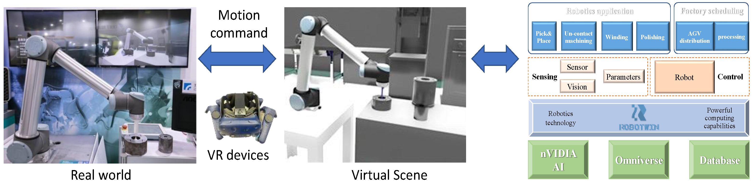
3.1. RoboTwin System
- Physics engines—These engines encompass physics models that are utilized to calculate the real-world reaction of the workpiece when it is physically picked or interacts with other objects.
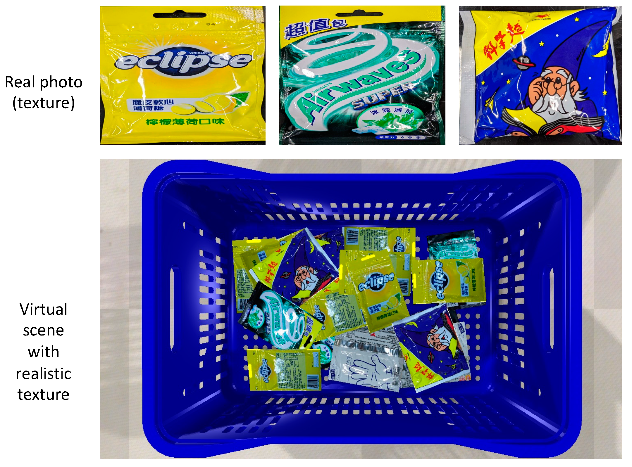
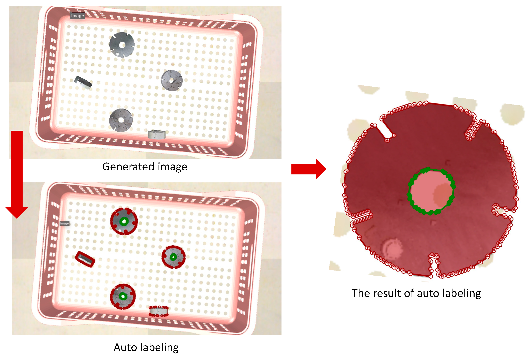
- Modeling and auto AI annotation tool—This tool facilitates the mapping of real-world textures onto the 3D CAD model of the workpiece and automates the generation of datasets with annotations indicating the pickable and unpickable points of each workpiece.
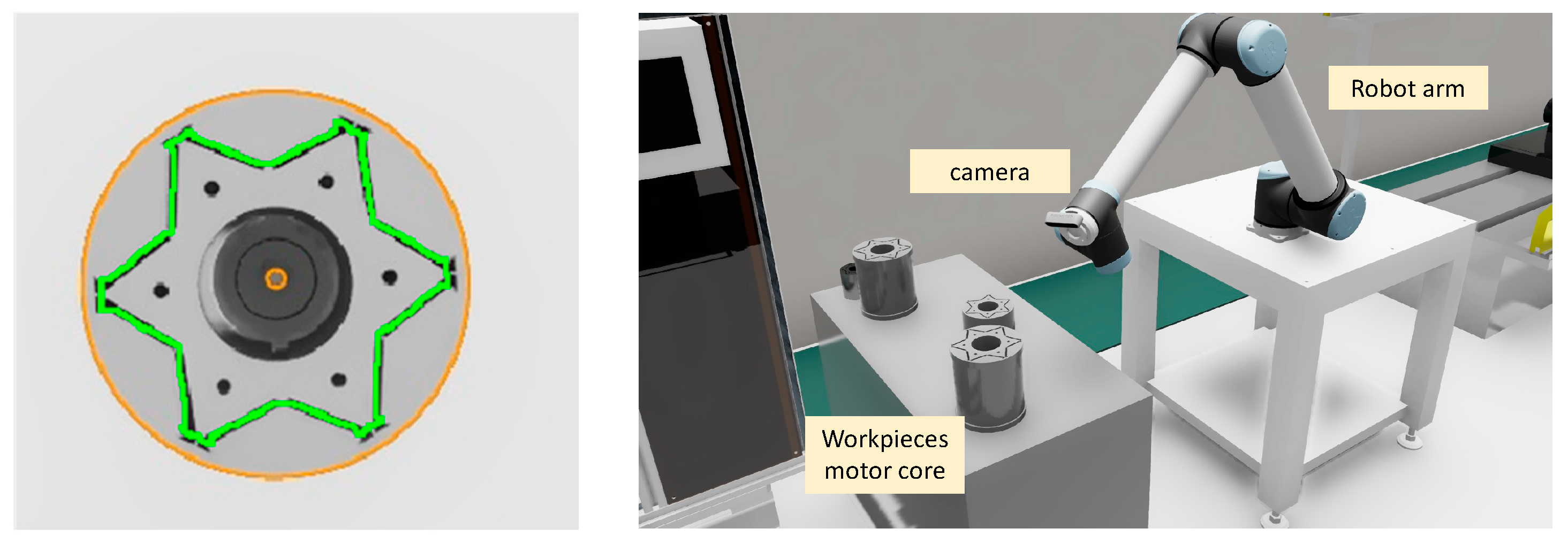
- Motion control—The motion control aspect encompasses robotic models equipped with motion control algorithms for the robotic arms and gripper reactions.
- VR modules—These modules provide an immersive experience for operators, allowing them to immerse themselves in a realistic virtual factory environment. This enables testing and fine-tuning of the robotic picking system.
- (1)
- Physics engines:
- (2)
- Modeling and Auto AI Annotation Tool:
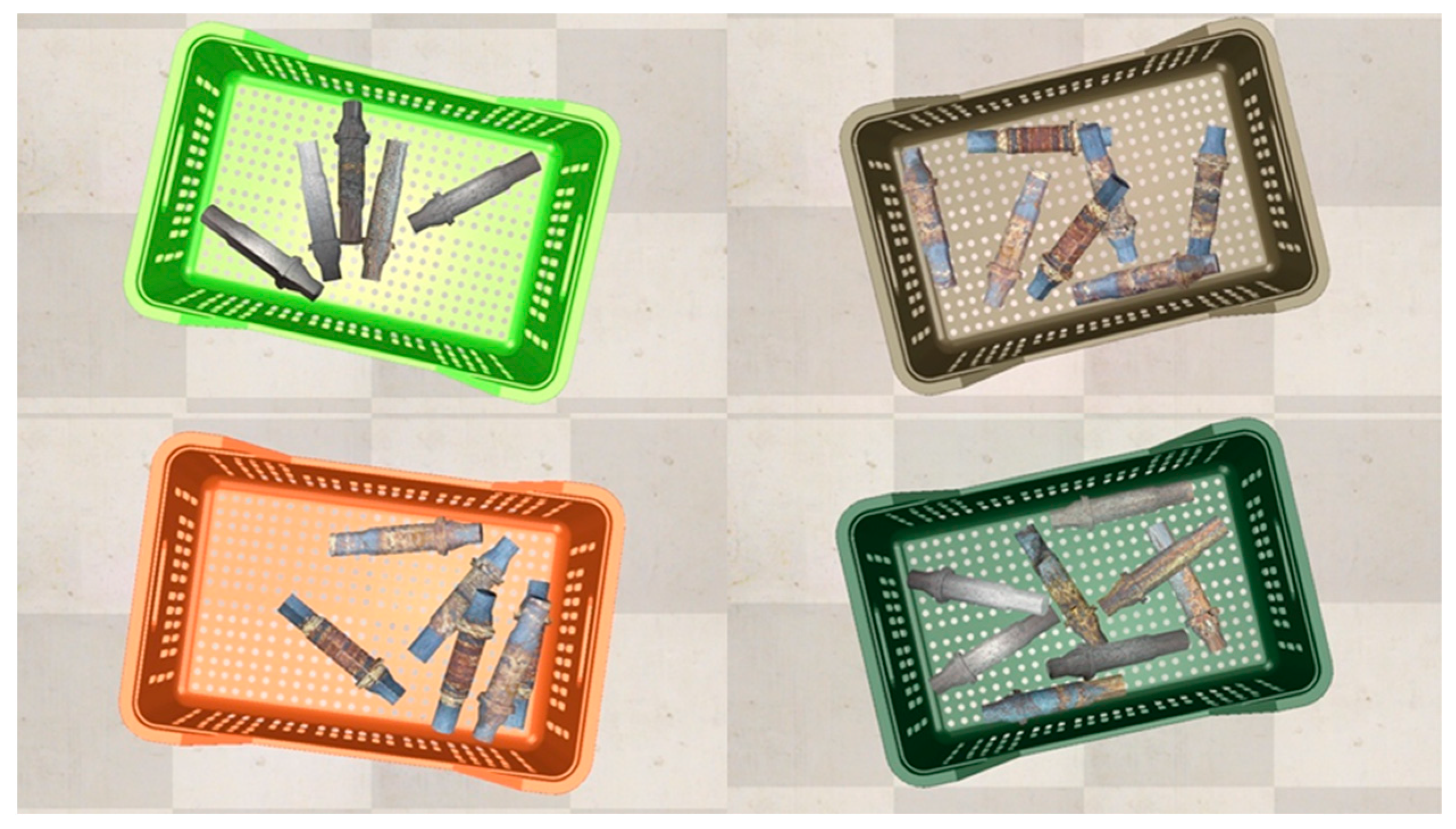
- Domain randomization (D): A function that takes multiple randomization parameters and initiates the scene randomly based on these values.
- Object posture (P): Random postures (x, y, z, rx, ry, rz) for the workpieces so each of them has a distinct posture and surface facing the camera while being randomly stacked inside a crate. Here, rx, ry, and rz represent the orientation or rotation angles with respect to the x-, y-, and z-axis, respectively.
- Quantity (Q): Random quantities of workpieces for each simulation scene. Depending on the quantities of workpieces, scenarios such as stacking and occlusion can have a higher probability of occurrence.
- Camera posture (CP): Random position for the camera to enhance or reduce workpieces in the image.
- Lighting posture (LP): Random posture for the lighting for each simulation scene so the light reflections are different.
- Light intensity (LI): Random light intensities are employed to simulate the light decay intensity.
- Light color (LC): Random light red, green, and blue colors (R, G, and B) influence the lighting in the scene.
- Color rendering (CR): Different color renderings of the objects are generated from the changes in the light sources. Only the high general color rendering index (Ra) allows the objects to show their natural color.
- (3)
- Motion control:
- (4)
- VR modules:
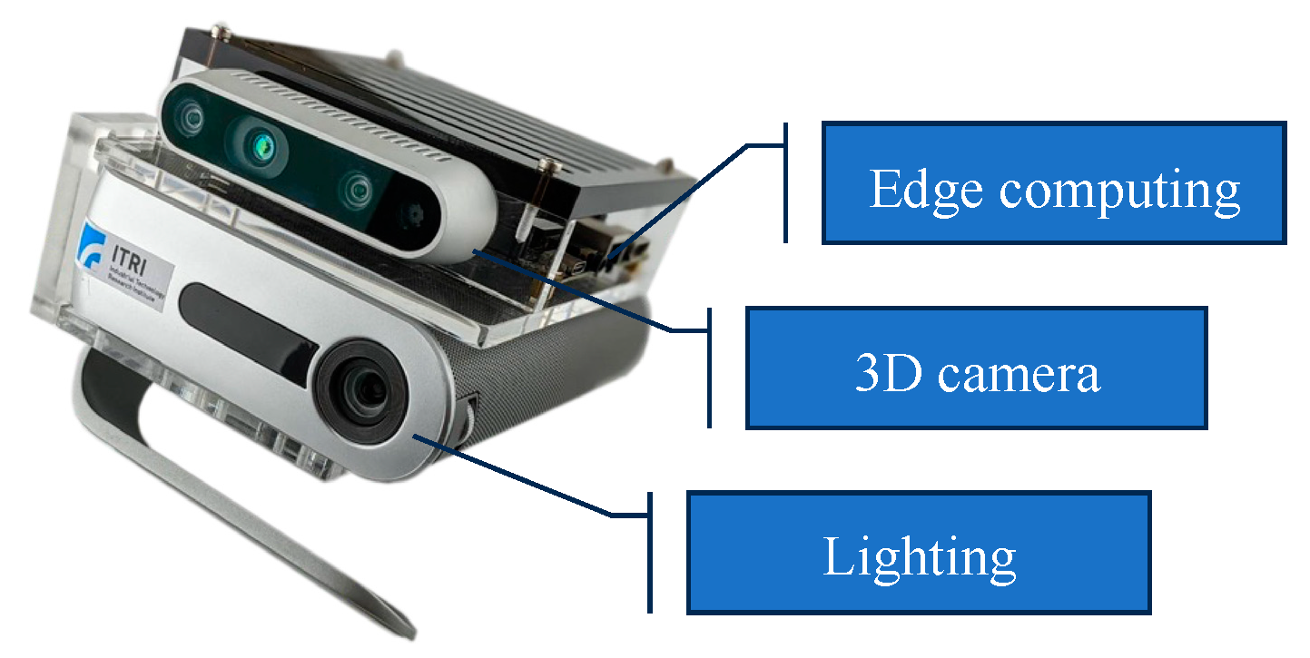
3.2. FOVision
4. Results
4.1. RoboTwin System
4.1.1. Physics Engines
4.1.2. Modeling and Auto AI Annotation Tool
4.1.3. Motion Control and VR Modules
4.2. FOVision System
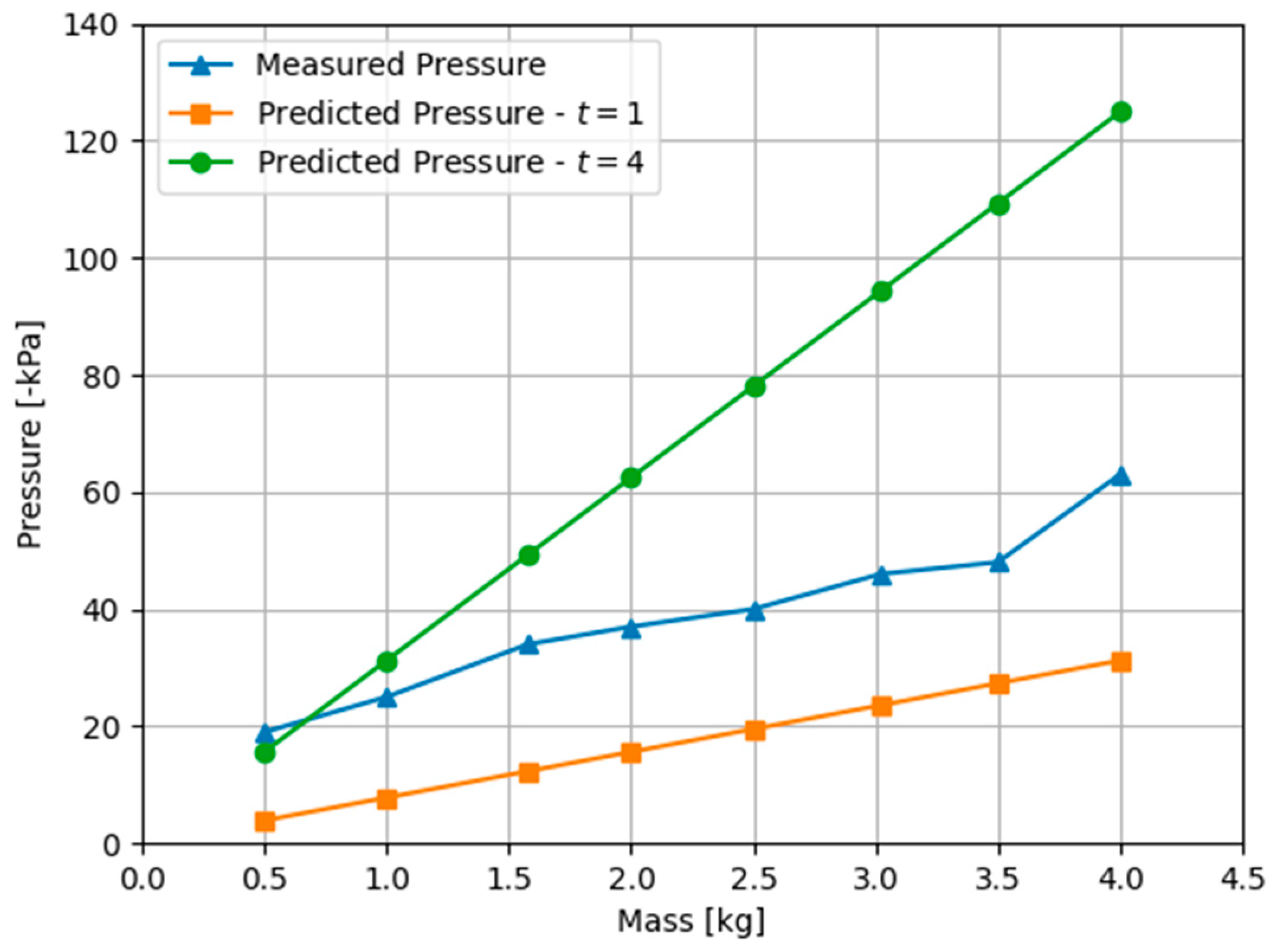
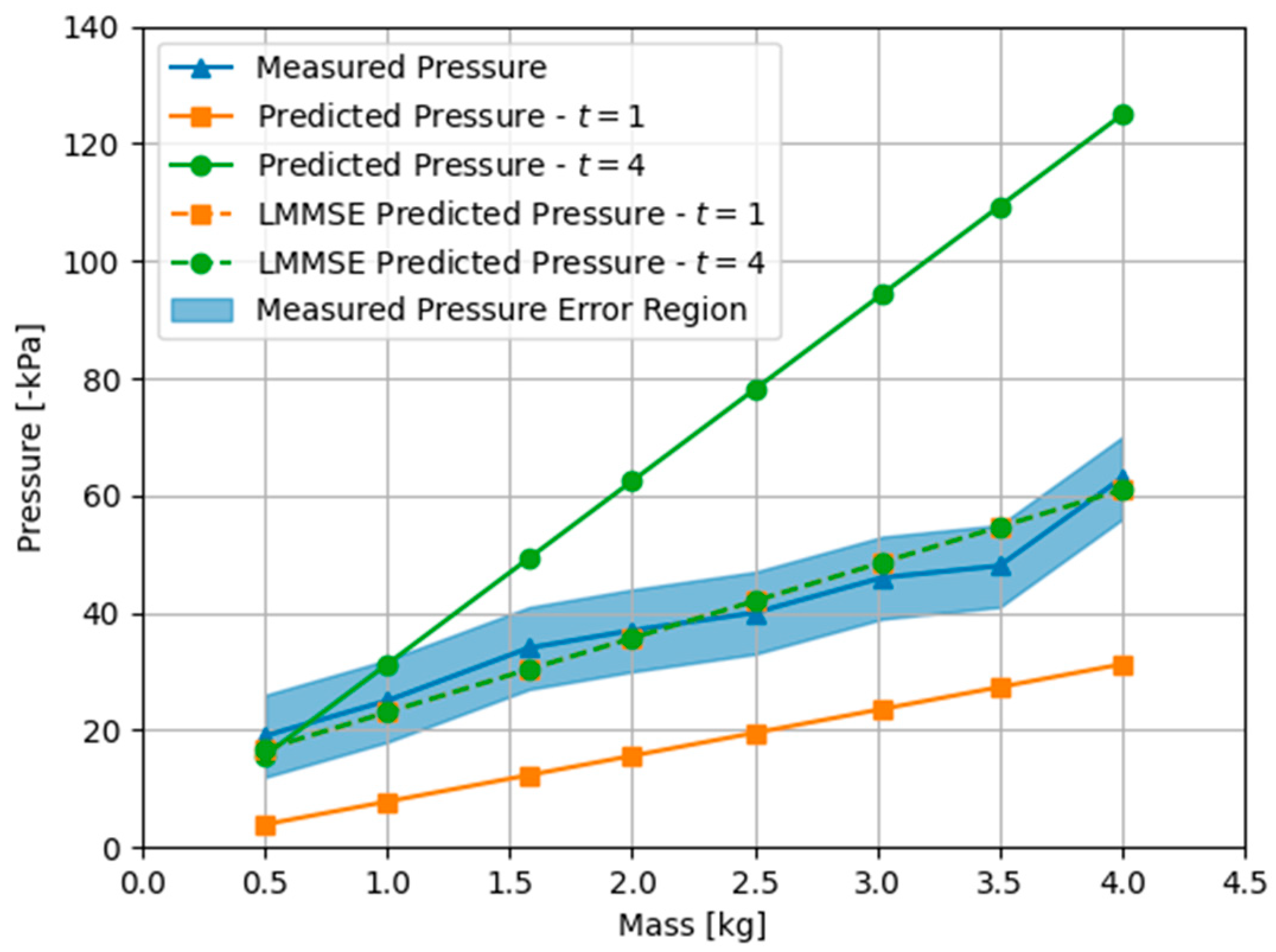
5. Discussion
6. Conclusions
Author Contributions
Funding
Institutional Review Board Statement
Informed Consent Statement
Data Availability Statement
Conflicts of Interest
References
- Rivera-Calderón, S.; Lázaro, R.P.-S.; Vazquez-Hurtado, C. Online assessment of computer vision and robotics skills based on a digital twin. In Proceedings of the 2022 IEEE Global Engineering Education Conference (EDUCON), Tunis, Tunisia, 28–31 March 2022; pp. 1994–2001. [Google Scholar] [CrossRef]
- Bansal, R.; Khanesar, M.A.; Branson, D. Ant Colony Optimization Algorithm for Industrial Robot Programming in a Digital Twin. In Proceedings of the 2019 25th International Conference on Automation and Computing (ICAC), Lancaster, UK, 5–7 September 2019; pp. 1–5. [Google Scholar] [CrossRef]
- Borangiu, T.; Răileanu, S.; Silişteanu, A.; Anton, S.; Anton, F. Smart Manufacturing Control with Cloud-embedded Digital Twins. In Proceedings of the 2020 24th International Conference on System Theory, Control and Computing (ICSTCC), Sinaia, Romania, 8–10 October 2020; pp. 915–920. [Google Scholar] [CrossRef]
- Paradis, S.; Hwang, M.; Thananjeyan, B.; Ichnowski, J.; Seita, D.; Fer, D.; Low, T.; Gonzalez, J.E.; Goldberg, K. Intermittent Visual Servoing: Efficiently Learning Policies Robust to Instrument Changes for High-precision Surgical Manipulation. In Proceedings of the 2021 IEEE International Conference on Robotics and Automation (ICRA), Xi’an, China, 30 May–5 June 2021; pp. 7166–7173. [Google Scholar] [CrossRef]
- Lee, C.-T.; Tsai, C.-H.; Chang, J.-Y. A CAD-Free Random Bin Picking System for Fast Changeover on Multiple Objects. In Proceedings of the ASME 2020 29th Conference on Information Storage and Processing Systems, Virtual, Online, 24–25 June 2020. [Google Scholar]
- Qiao, S.; Zhu, Y.; Adam, H.; Yuille, A.; Chen, L.-C. ViP-DeepLab: Learning Visual Perception with Depth-Aware Video Panoptic Segmentation. In Proceedings of the 2021 IEEE/CVF Conference on Computer Vision and Pattern Recognition (CVPR), Nashville, TN, USA, 20–25 June 2021; pp. 3996–4007. [Google Scholar] [CrossRef]
- Shen, X.; Yang, J.; Wei, C.; Deng, B.; Huang, J.; Hua, X.; Cheng, X.; Liang, K. DCT-Mask: Discrete Cosine Transform Mask Representation for Instance Segmentation. In Proceedings of the 2021 IEEE/CVF Conference on Computer Vision and Pattern Recognition (CVPR), Nashville, TN, USA, 20–25 June 2021; pp. 8716–8725. [Google Scholar] [CrossRef]
- Ganea, D.A.; Boom, B.; Poppe, R. Incremental Few-Shot Instance Segmentation. In Proceedings of the 2021 IEEE/CVF Conference on Computer Vision and Pattern Recognition (CVPR), Nashville, TN, USA, 20–25 June 2021; pp. 1185–1194. [Google Scholar] [CrossRef]
- Chen, Y.; Li, Y.; Kong, T.; Qi, L.; Chu, R.; Li, L.; Jia, J. Scale-aware Automatic Augmentation for Object Detection. In Proceedings of the 2021 IEEE/CVF Conference on Computer Vision and Pattern Recognition (CVPR), Nashville, TN, USA, 20–25 June 2021; pp. 9558–9567. [Google Scholar] [CrossRef]
- Geus, D.D.; Meletis, P.; Lu, C.; Wen, X.; Dubbelman, G. Part-aware Panoptic Segmentation. In Proceedings of the 2021 IEEE/CVF Conference on Computer Vision and Pattern Recognition (CVPR), Nashville, TN, USA, 20–25 June 2021; pp. 5481–5490. [Google Scholar] [CrossRef]
- Yuan, H.; Veltkamp, R.C. PreSim: A 3D Photo-Realistic Environment Simulator for Visual AI. IEEE Robot. Autom. Lett. 2021, 6, 2501–2508. [Google Scholar] [CrossRef]
- Simon, D.; Farber, M.; Goldenberg, R. Auto-Annotation Quality Prediction for Semi-Supervised Learning with Ensembles. In Proceedings of the 2020 IEEE/CVF Conference on Computer Vision and Pattern Recognition Workshops (CVPRW), Seattle, WA, USA, 14–19 June 2020; pp. 3984–3988. [Google Scholar] [CrossRef]
- Asadi, A.R. Cognitive Ledger Project: Towards Building Personal Digital Twins Through Cognitive Blockchain. In Proceedings of the 2021 2nd International Informatics and Software Engineering Conference (IISEC), Ankara, Turkey, 16–17 December 2021; pp. 1–5. [Google Scholar] [CrossRef]
- Tuleja, P.; Šidlovská, L. Unilateral gripping with active vacuum suction cup Calculation of gripping force and number of suction cups. Transf. Inovacii 2014, 29, 232–235. [Google Scholar]
- Liu, T.; Xu, H.; Zhang, X. 3D Clothing Transfer in Virtual Fitting Based on UV Mapping. In Proceedings of the 2018 11th International Congress on Image and Signal Processing, BioMedical Engineering and Informatics (CISP-BMEI), Beijing, China, 13–15 October 2018; pp. 1–6. [Google Scholar] [CrossRef]
- Miyazawa, K.; Maeda, Y.; Arai, T. Planning of graspless manipulation based on rapidly-exploring random trees. In Proceedings of the (ISATP 2005). The 6th IEEE International Symposium on Assembly and Task Planning: From Nano to Macro Assembly and Manufacturing, Montreal, QC, Canada, 19–21 July 2005; pp. 7–12. [Google Scholar] [CrossRef]
- Tsai, C.-H.; Chang, J.-Y. A New approach to enhance artificial intelligence for robot picking system using auto picking point annotation. In Proceedings of the ASME 30th Conference on Information Storage and Processing Systems, Virtual, 2–3 June 2021. [Google Scholar] [CrossRef]


| Parameters | Value |
|---|---|
| 0 (Push the object toward the Suction Pad) | |
| 0.5–4 kg | |
| 10–160 kpa | |
| 0.04 m | |
| 1 (Suction pad must be parallel to the ground) | |
| {1, 4} (Safety factor introduced by authors in [14] to account for the orientation of gripper) |
| Model | Train Size | Validation Size | Using Auto Tool | mAP70 |
|---|---|---|---|---|
| YOLO3 | 2700 | 300 | YES | 0.713 |
| YOLO3 | 2700 | 300 | NO | 0.423 |
| Item | Annotation Type | Annotation Speed |
|---|---|---|
| Manpower | Bounding box | 60 img/hr |
| Instance segmentation | 12 img/hr | |
| RoboTwin System | Bounding box | 2000 img/hr |
| Instance segmentation | 1000 img/hr |
| Workpiece | Cycle | Success | Success Rate |
|---|---|---|---|
| Wrench | 500 | 400 | 80% |
| Drive shaft | 120 | 100 | 83% |
Disclaimer/Publisher’s Note: The statements, opinions and data contained in all publications are solely those of the individual author(s) and contributor(s) and not of MDPI and/or the editor(s). MDPI and/or the editor(s) disclaim responsibility for any injury to people or property resulting from any ideas, methods, instructions or products referred to in the content. |
© 2023 by the authors. Licensee MDPI, Basel, Switzerland. This article is an open access article distributed under the terms and conditions of the Creative Commons Attribution (CC BY) license (https://creativecommons.org/licenses/by/4.0/).
Share and Cite
Tsai, C.-H.; Hernandez, E.E.; You, X.-W.; Lin, H.-Y.; Chang, J.-Y. RoboTwin Metaverse Platform for Robotic Random Bin Picking. Appl. Sci. 2023, 13, 8779. https://doi.org/10.3390/app13158779
Tsai C-H, Hernandez EE, You X-W, Lin H-Y, Chang J-Y. RoboTwin Metaverse Platform for Robotic Random Bin Picking. Applied Sciences. 2023; 13(15):8779. https://doi.org/10.3390/app13158779
Chicago/Turabian StyleTsai, Cheng-Han, Eduin E. Hernandez, Xiu-Wen You, Hsin-Yi Lin, and Jen-Yuan Chang. 2023. "RoboTwin Metaverse Platform for Robotic Random Bin Picking" Applied Sciences 13, no. 15: 8779. https://doi.org/10.3390/app13158779