Article

Power-Split Hybrid Train Configuration Design Based on a Single-Row Star Row

1
China National Railway Locomotive & Rolling Stock Industry Corporation (CRRC) Dalian Institute Co., Ltd., Dalian 116085, China
2
State Key Laboratory of Mechanical Transmission, Chongqing University, Chongqing 400044, China
*
Author to whom correspondence should be addressed.
Appl. Sci. 2023, 13(12), 7279; https://doi.org/10.3390/app13127279
Submission received: 24 April 2023 / Revised: 16 June 2023 / Accepted: 17 June 2023 / Published: 19 June 2023
(This article belongs to the Special Issue Transmission Mechanics: From Theory to Application)

Abstract

:

Featured Application

Rail transportation is still quite competitive according to studies on hybrid diesel engines used for rail freight propulsion. Increase the economy and the dynamics.

Abstract

The fundamental component of a hybrid train system is the hybrid power-coupling mechanism. This paper proposes a single-row star-row power-split arrangement for the power-coupling method in a hybrid train. In order to create input and output power-split configuration schemes for a hybrid train power mechanism, a graphical–theoretical model and a relationship matrix were first established. An electromechanical path power proportion equation was then established to filter out two input power-split configurations. The working states of three developed hybrid power-coupling mechanism schemes were studied to find the scheme that fulfills hybrid train design criteria to meet the power, operating mode, and spatial structural arrangement requirements. Finally, by creating a simulation model for the entire vehicle, the dynamics, battery state of charge (SOC) value, and overall vehicle efficiency for the configuration were simulated and examined. The findings demonstrate that the single-row star-row power-split design technique presented here significantly enhances the train performance.

1. Introduction

In 2017, in Europe, the transportation sector contributed 27.9% of greenhouse gas (GHG) emissions and 30.8% of ultimate energy consumption [1]. Rail freight is more energy-efficient and emits 3.5 times fewer greenhouse gases than automobile freight [2]. Rail transportation is still quite competitive according to studies on hybrid diesel engines used for rail freight propulsion [3]. Many nations have suggested supporting the creation of cutting-edge rail transportation technologies. Hybrid trains were developed to satisfy transportation needs while considering fuel consumption and emissions, which served as a response to the government’s push for innovation-driven, green developments and the rising awareness of environmental concerns. However, little has been carried out to evaluate the operational performance of replacing diesel trains with hybrid trains on the same track. Fuel usage and power output are significantly impacted by the train design. The hybrid train power system configuration was thus improved to further enhance the economy and dynamics of hybrid trains. The mechanical construction of the hybrid system connects the engine to the motor, and a power-coupling device can be employed to boost the overall vehicle power output. The split hybrid power system can continuously optimize the engine speed and torque over a wide range of vehicle speeds because it uses a planetary gear arrangement to decouple the engine from the wheels.
The public praised the Prius for its exceptional fuel-saving capabilities when it was introduced for mass production in Japan in 1997 [4,5]. Donateo [6] proposed the design of a series/parallel hybrid electric power system to increase safety and optimize the fuel economy by controlling the engine working points. Li [7] presented a novel composite power-split hybrid system based on two planetary gear sets for commercial vehicles. Six operating modes were analyzed by means of a simplified combined lever diagram and power performance and economic performance simulations were carried out, and the results show that the proposed configuration has a significant fuel-saving performance. Yang [8] proposed a powertrain configuration scheme design method based on hierarchical topological graph theory. The kinematic and dynamical modeling of the powertrain, classification of configuration modes, and synthesis of scenarios for power-split hybrid electric vehicles (PS-HEVs) were carried out. The powertrain configuration of PSHEVs is the basis of energy management, which determines the operating mode, control algorithm selection, and optimization potential, and directly affects the vehicle’s comprehensive performance [9]. Thirty-two novel hybrid transmissions consisting of a Ravigneaux gear train and a single planetary gear train were synthesized using a creative design methodology based on graph theory and the lever analogy method. The design process commences by identifying an existing transmission configuration that meets all of the design requirements [10]. In order to raise the transmission ratio of the train, Li [11] proposed an innovative design of a half-toroidal planetary traction train (half-toroidal PT) with a continuously variable planetary ratio. Cammalleri [12] proposed a new matrix approach for identifying the basic functional parameters underlying the model from the constructive layout of the transmission. Using a globally optimal control method based on the dynamic programming (DP) technique, Hu [13] simulated the best economic scenario and the best power performance of the configuration scheme generated for their proposed single-row star-row split hybrid powertrain configuration design scheme. Wang [14] established a transient optimal control to regulate the power flow of a power-split hybrid vehicle with a dual planetary gear set as the focus. Lin [15] proposed a mechatronic model for an HEV powertrain and investigated the control of electric motors in the powertrain, and the results show that electric motors are not only meaningful for improving the comfort of the vehicle but also for reducing the fatigue life loss of planetary gear sets both in pure electric vehicle mode and in hybrid vehicle mode. To analyze the kinematics and dynamics of single- and double-row planetary coupling mechanism transmission systems, Yang et al. [16] created a graphical model for the planetary coupling transmission system in hybrid vehicles. Zhang [17] searched a vast topological space for various powertrain configurations that could match or exceed the acceleration and fuel efficiency of the Volt Gen 2. Under derived design limitations, Ngo and Yan [18] methodically synthesized practicable series–parallel hybrid transmission topologies for automotive systems that are utilized in passenger cars. Alparslan Emrah Bayrak [19] suggested design approaches that consider single- and multi-mode topologies, various numbers of planetary gears, and various powertrain parts. Pei [20] suggested a hierarchical topology map technique and used a dynamic planning algorithm to analyze the fuel efficiency and acceleration performance (0–100 km/h) of the configuration for various driving cycles. T. CIOBOTARU [21] suggested a method for analyzing epicyclic gearboxes by evaluating the speeds, torques, and power of the external elements in epicyclic gear mechanisms, as well as the total ratios of the gear box. A better dynamic and economic performance of vehicles can be produced by increasing the number of gears of planetary gear trains (PGTs), but a more complex structure would be required [22]. In order to increase the competitiveness of railroad transportation and decrease environmental pollution, a more popular design is the single-row star-row split power-coupling mechanism. Currently, hybrid train designs hardly ever consider the actual transmission ratio and layout space requirements of the power-coupling mechanism. Mechanical transmissions for rail vehicles based on planetary gear sets can transmit up to approximately 600 kW per propulsion unit due to weight and burden considerations. The hybrid energy group used in this paper has an output of 500 kW and the power battery has a rated power of 150 kW and a capacity of 152 kWh, so the subject of this paper is a hybrid small locomotive based on diesel engine.
This paper is therefore aimed at filling the existing gap in the state of the art. In order to meet the practical power and economy needs of train operation and long-distance travel, a graphical–theoretical model and a relationship matrix were established during this study, and a single-row star-row hybrid coupling mechanism was selected as the power-split element by a dynamic planning algorithm and the ratio of electric power to engine power. Simulations then verified that the design configuration could successfully improve the power and fuel economy of a train.

2. Configuration Choice

2.1. Method of Selecting the Configuration

As illustrated in Figure 1 and Table 1, a graphical–theoretical model was employed during this study to visualize the connection links between the power elements, the power-switching elements, and the planetary row components through various point–line connections. Following the description of the connection relationship by the dynamics matrix, the generation of the connection matrix by the traversal method, and the establishment of the electromechanical path power proportion equation, an appropriate configuration scheme was solved by inversion.
The graphical–theoretical model shown in Figure 1 can be described using Equation (1).
[ T 0 ] = [ B 0 ] [ ω ˙ 0 ] [ T O T E T M 1 T M 2 0 0 0 0 ] = [ J O 0 0 0 0 0 0 0 0 J E 0 0 0 0 0 0 0 0 J M 1 0 0 0 0 0 0 0 0 J M 2 0 0 0 0 0 0 0 0 J R 0 0 K 0 0 0 0 0 J C 0 1 + K 0 0 0 0 0 0 J S 1 0 0 0 0 K 1 + K 1 0 ] [ ω ˙ O ω ˙ E ω ˙ M 1 ω ˙ M 2 ω ˙ R ω ˙ C ω ˙ S F ]
In Equation (1), T0 is the torque matrix, B0 is the characteristic relationship matrix, ω0 is the angular acceleration matrix, JO, JE, JG, and JM are the rotational inertias of the power elements, JR, JC, and JS are the rotational inertias of the planetary row members, F is the internal force between the gears, and K is the characteristic parameter of the planetary row gears, which is equal to the ratio of the number of teeth in the ring and sun gears.
The matrix in Equation (1) must be transformed according to the connection relationship between the power elements and the planetary row components when using the graphical–theoretical method to select the configuration. The established relationship matrix can then be used to create the fundamental conditions for the configuration search. Equation (2) displays the connection matrix that was built.
[ T 0 ] = [ J D D T 0 ] [ ω ˙ F ]
In Equation (2), T 11 = T O , T 21 = T E , T 31 = T M 2 , J 11 = J O + J M 1 + J R , J 22 = J E + J C , J 33 = J M 2 + J S , D 11 = K , D 12 = 1 + K , D 13 = 1 , ω ˙ 11 = ω ˙ O , ω ˙ 21 = ω ˙ E , ω ˙ 31 = ω ˙ M 2 .
The remaining elements are equal to zero, J denotes the rotational inertia of the power element and the planetary row members, and D and DT denote the connection relationship between the power element and the planetary row members.

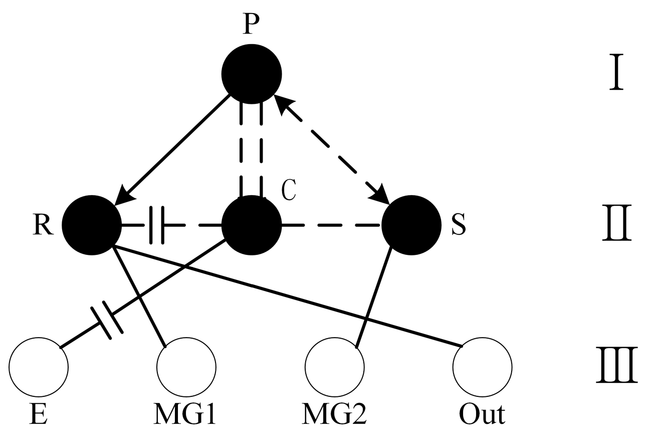
2.2. Single-Row Star-Row Power-Split Configuration

The planetary row gear set ratio and the placement of the motor both impact the power-split characteristics. Depending on the different motor locations, the single-row star-row power-split mechanism can be classified as an input power-split mechanism or an output power-split mechanism. Power splitting causes a unique power cycling phenomenon between power components. As a result, the proportion of power in the electromechanical path increases and the system efficiency decreases. The transmission ratio of the transmission system is defined as i = ωE/ωOut and the mechanical point of the working state of the transmission ratio is referred to as iMP. The magnitude of the relationship between the two impacts the production of the power cycle phenomena.
A single row of a star row in one of the nodes in this study can only be connected to two power components simultaneously, and the power components include the motor, the engine, and the output shaft, when designing the configuration scheme. The selection process begins from the perspective of the connecting nodes and considers that the design configuration must achieve variable speed adjustment. Figure 2 illustrates an input split arrangement with six connection options when the motor and output are linked at the same node.
An MG2 motor is connected to the output in the configuration indicated in Figure 2, and the speed–torque coupling equation for the planetary row is presented in Equation (3), which determines the torque–speed relationship between the input power element and the output element.
{ T M 2 = 1 α T E T M 1 = T Out α 1 α T E ω M 2 = ω Out ω M 1 + ( α 1 ) ω O u t α ω E = 0
The ratio of the electromechanical path power to the engine output power for the input distributed configuration is shown in Equation (4).
{ η M 1 = T M 1 ω M 1 T E ω E = 1 i 1 1 α i = i MP i 1 η M 2 = T M 2 ω M 2 T E ω E = 1 1 i + 1 α i = 1 i MP i
α in Equation (4) is related to the characteristic parameter K of the planetary row. The corresponding α values for the six input distributive configurations are α1 = K/(1 + K), α2 = −K, α3 = 1/(1 + K), α4 = (1 + K)/K, α5 = −1/K, and α6 = 1 + K.
Option (f) was chosen for analysis. Equation (4) indicates that the power-split phenomenon happens when i > iMP, ηM1 < 0, and ηM2 > 0. At this time, MG1 is the generator, MG2 is the motor, electrical power flows from MG1 to MG2, and the output mechanical power of MG2 converges to that of the output shaft. The power circulation phenomenon happens when i < iMP, ηM1 > 0, and ηM2 < 0; then, MG2 is the generator, MG1 is the motor, electrical power flows from MG2 to MG1, and the direction of power flow is opposite that of the mechanical power flow.
Figure 3 illustrates an output distribution configuration with six possible connections for the engine and the motor at the same node.
Equation (5) describes the torque–speed relationship between the power input element and the output element of the output split configuration according to the analysis of the input split configuration.
{ T M 1 = 1 β 1 T Out T E T M 2 = 1 β 1 T Out ω M 1 = ω E ω M 2 + ( β 1 ) ω Out β ω E = 0
Equation (6) displays the ratio of the electromechanical path power to the engine output power for the input distribution design.
{ η M 1 = T M 1 ω M 1 T E ω E = β i β 1 + 1 = i i MP 1 η M 2 = T M 2 ω M 2 T E ω E = β i β 1 + 1 = 1 i i MP
β in Equation (6) is related to the characteristic parameter K of the planetary row, and the corresponding β values for the six input distributive configurations are β1 = K/(1 + K), β2 = −K, β3 = 1/(1 + K), β4 = (1 + K)/K, β5 = −1/K, and β6 = 1 + K.
Option (b) was chosen for this analysis. According to Equation (6), the power cycle phenomenon occurs when i > iMP, ηM1 > 0, and ηM2 < 0. At this moment, MG2 is the generator, MG1 is the motor, and electrical power flows from MG2 to MG1 in the direction opposite to that of the mechanical power flow. When i < iMP, ηM1 < 0, and ηM2 > 0, MG1 is the generator, MG2 is the motor, electrical power flows from MG1 to MG2 in the same direction as that of the mechanical power flow, the mechanical power produced by MG1 eventually converges to the output shaft power, and the power-split phenomenon occurs.

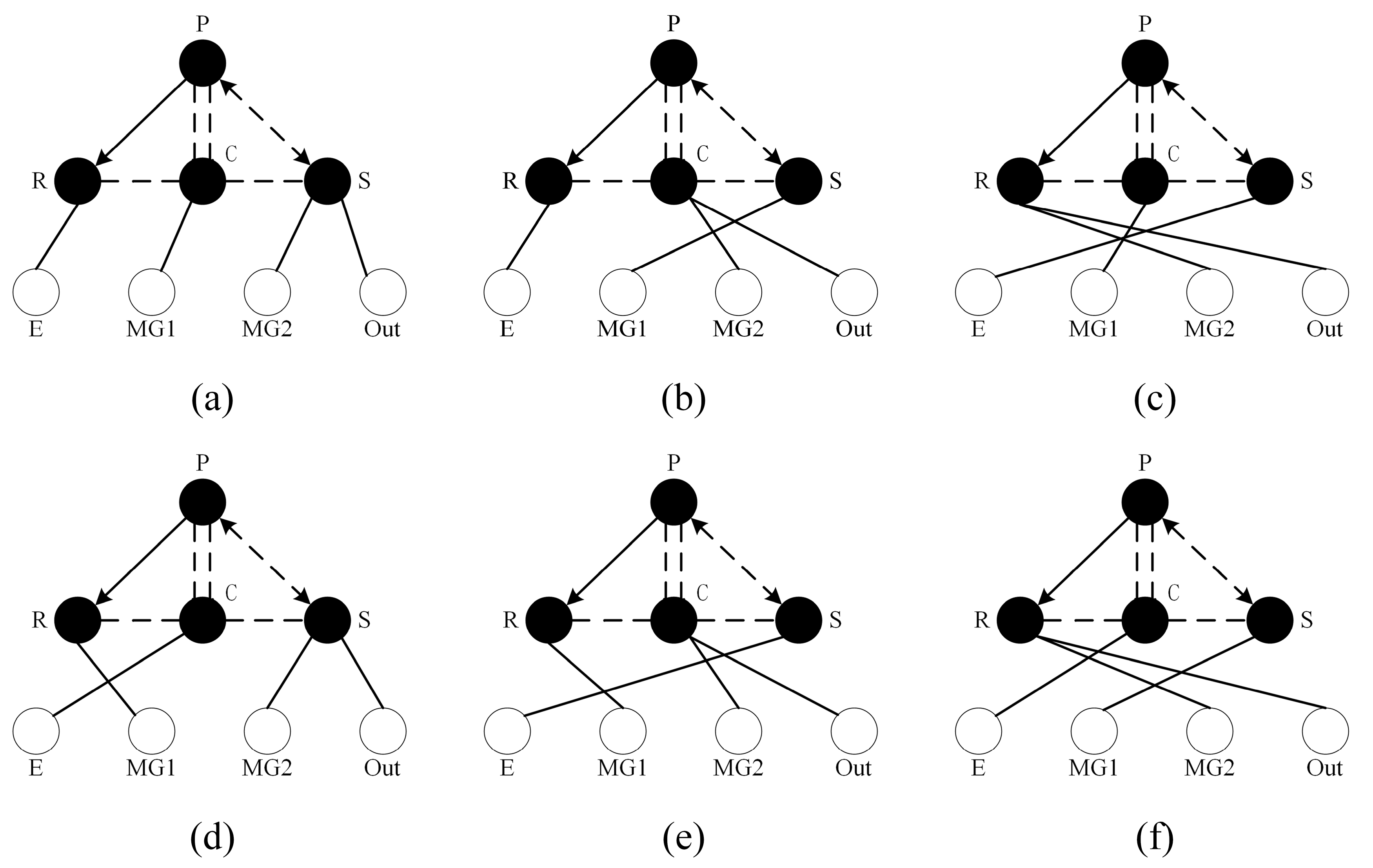
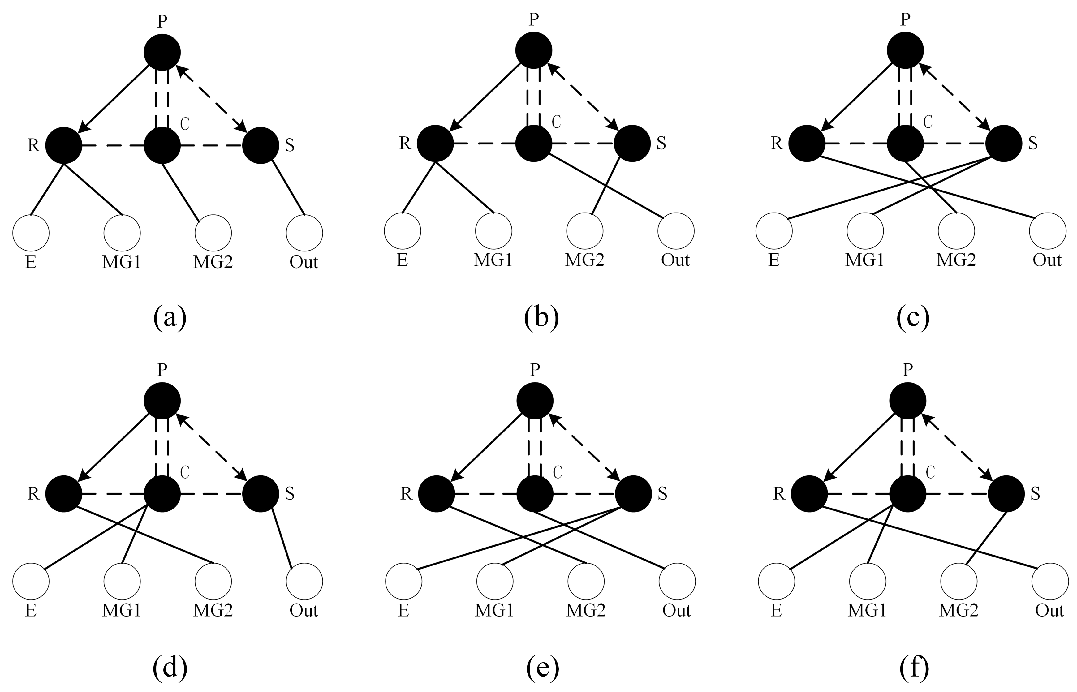
3. Preliminary Configuration Scheme Selection

The ratio of the electromechanical path power to the engine output for the power-splitting structure should be lowered; a numerical analysis was performed to decide between the configurations that were previously proposed. The range of the planetary row member characteristic parameters was [1.5, 3], whereas the drive system transmission ratio range was [0, 5]. Equations (4) and (6) show that the ratios of the electrical power to the engine power for the two motors in the input and output distribution configurations were opposite each other. The numerical simulation results obtained by taking the absolute value of the ratio from the numerical analyses are shown in Figure 4.
The ratio of the electrical power of the electromechanical path to the mechanical power output of the engine for the power-split configuration should satisfy η ≤ 1 and be as small as possible. The acceleration time for a train (0–100 km/h) was used as the assessment index for evaluating the power performance of each scheme. Schemes (a) and (c) in Figure 4a have η > 1 when the transmission ratio range is [0, 5], so neither of them satisfies the requirements. When the transmission ratio is in the [0, 5] range, schemes (a) and (c) in Figure 4b have η > 1. The growth rate for scheme (d) is excessive, so it restricts the transmission ratio options and the scheme falls short of the criteria. In the search for solutions with better dynamics, the schemes with acceleration times longer than 90 s (schemes (d) and (e) in Figure 4) were eliminated after the performance was assessed for the remaining configurations.
The calculation procedure begins with dividing the speed into N equal parts; next, Equations (3) and (5) determine the speed–torque relationship for the corresponding configuration, in addition to establishing the maximum acceleration as the objective function, designing the control variables, and calculating the acceleration time. Finally, all the calculated hybrid train configurations and their acceleration times are shown in Figure 5.
Figure 5 shows that the large acceleration times of the input and output split schemes (e) and (f) force their elimination. The gap between the power performance values for output split scheme (b) and input split scheme (f) is the smallest, but because the transmission ratio of scheme (b) is > 3, there are more restrictions on the subsequent design of the planetary row gear set. Therefore, schemes (b) and (f) in the input split configuration were chosen for the structural design in this study.

4. Analysis and Design of the Configuration Scheme

4.1. Design Analysis When Using Scheme (b)

A hybrid box must use power-switching components to provide seamless switching between operating modes and to guarantee an acceptable spatial structural layout, in addition to meeting the dynamics requirements for train operation. In this study, two input power-split configurations were used to build three hybrid box structures. Figure 6a depicts the hybrid power-coupling mechanism scheme created in accordance with plan (b).
The power of the MG1 motor is transferred to the sun gear by one gearing stage, the output shaft of the MG2 motor is connected to the planetary carrier, and the engine power in this scheme must be transferred to the gear ring through two parallel stage gears.
This scheme has a greater variety of operating mode types and stricter criteria for mode-switching control that make implementation more challenging. The number of parallel-stage gears is relatively large, which results in a low system efficiency, while the structure is complex and does not meet the spatial arrangement requirements; thus, this structure was excluded.

4.2. Design Analysis When Using Scheme (f)

During this study, two structural organization techniques for the (f) scheme configuration were proposed. The first was a system with a brake and a clutch, as shown in Figure 6b.
The planetary frame is connected to the engine through a clutch, the power from motors MG1 and MG2 is passed to the gear ring and sun gear, respectively, through a pair of parallel-stage gears, and brakes are used to stop the sun gear shaft and the planetary frame shaft. The hybrid box can be made to run in various operating modes by changing the operating states of the clutch and the brake.
This scheme can accommodate the power needs of the hybrid train, and switching between the operational modes is simple to implement. The installation position of the power-switching element must be modified to minimize its number since the axial length of the design exceeds the size requirement of its reserved space in the hybrid box. The structural scheme that results from this redesign is depicted in Figure 6c.
This solution has two clutches arranged at the input and output as power-switching elements, and the axial dimensions are significantly reduced compared to the (b) solution. The engine and MG1 are connected to the planetary carrier and the gear ring, respectively, and MG2 uses a series of helical gears to deliver power to the sun gear. In this scheme, the hybrid mode can be separated into four sub-modes since it can be used to drive or charge both MG1 and MG2.
There are several sub-modes for each operating mode, and the operating states of the power-switching elements are the same for each sub-mode, making the solution very flexible. An appropriate sub-mode can be chosen according to the current needs without changing the operating state of the clutch.

5. Simulation Analysis

Based on details regarding the track conditions and the speed requirements for the train, a simulation analysis was conducted using a known railroad operating route as the input.
Figure 7 shows the effective fuel consumption rate of the engine obtained from the engine bench test. According to the operating point distribution of the engine in Figure 8a,b, it can be determined that the effective fuel consumption rates of an internal combustion engine train and the hybrid train are concentrated in the 200–250 g/kWh and 0–200 g/kWh ranges, respectively. This result shows that the hybrid train has a better fuel economy than the internal combustion engine train. Figure 8b,c show that the primary functions of MG1 and MG2 are driving and charging, respectively. When the train is moving quickly, MG1 can supply additional power to decrease the engine load rate and return the engine operating point to the economic zone. In order to keep the engine operating in the economic zone when the train is moving slowly, MG2 functions as a “load” by producing electricity to increase the engine load rate and decrease the backup power.
Figure 9 shows that the effective fuel consumption rate of the designed hybrid train is less than 200 g/kWh during operation, which is consistent with the engine operating point distribution in Figure 8b.
The battery operating parameters obtained from the simulation are shown in Figure 10.
The battery input and output power results were divided into 11 intervals according to the train operating stations as shown in Figure 10a, and each interval was divided into three states: acceleration, high-speed driving, and deceleration. The red dashed line serves as the dividing line between acceleration and high-speed driving, whereas the green dashed line serves as the deceleration line. The operating voltage and current of the battery are shown in Figure 10b,c, respectively.
Several inferences can be drawn from Figure 10. Both the input and output power of the battery fall between −300 and 300 kW, the working voltage is in the 592–680 V range, and the operating current is in the −441–507 A range. When the battery operates at high power, the train is either in the acceleration or the deceleration state. As the train accelerates, the high-power drive motor from the battery must supply additional energy to maintain the power performance of the train. In addition, the acceleration process of the train includes a low-speed, high-load phase. During this phase, the battery output of the high-power drive motor can simply adjust the operating point of the engine to maximize the fuel efficiency; during deceleration, the high-power motor can charge the battery and increase the energy efficiency.
According to Figure 10d, during hybrid train operation, the SOC decreases from 100% to 65.7%. Additionally, the train has more stations and we expect a pure electric drive mode at startup, which requires more power from the battery; thus, we set the SOC balance point to 60% in the controller, and it fluctuates by ±6%.

6. Conclusions

In this study, the following conclusions were drawn.
  • The small locomotive is clearly identified as the research object of this paper, and the total power output is 540 kW. Input and output power-split configurations were analyzed according to the connection characteristics of the single-row star row, and a graphical–theoretical model and a relationship matrix for the configuration design were established.
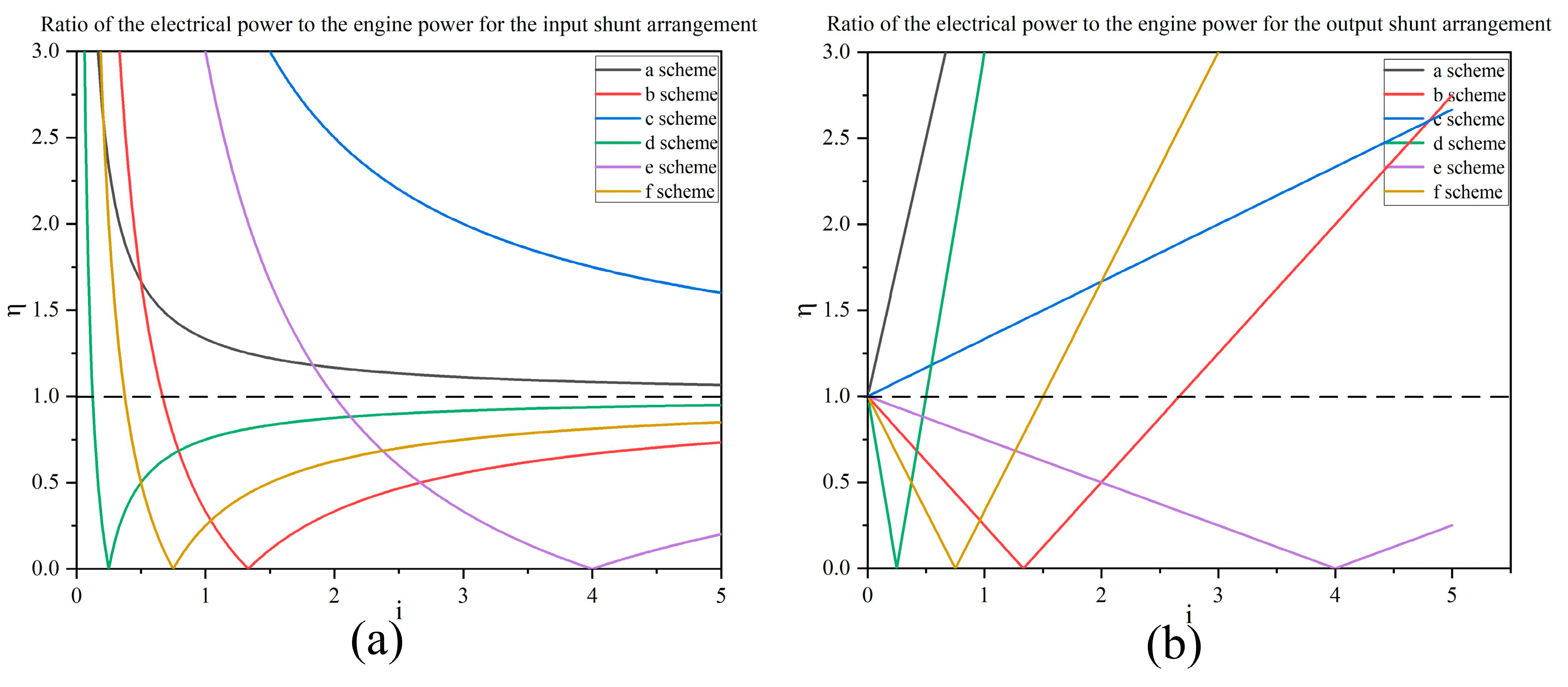
  • Firstly, two input distributed power-splitting schemes that meet the conditions were determined based on the ratio of electric power to engine power and dynamic planning algorithm. Three hybrid coupling mechanism schemes were constructed for the above two configuration schemes with consideration of the working mode and space structure layout requirements. The scheme that meets the design requirements of the hybrid train was finally selected.
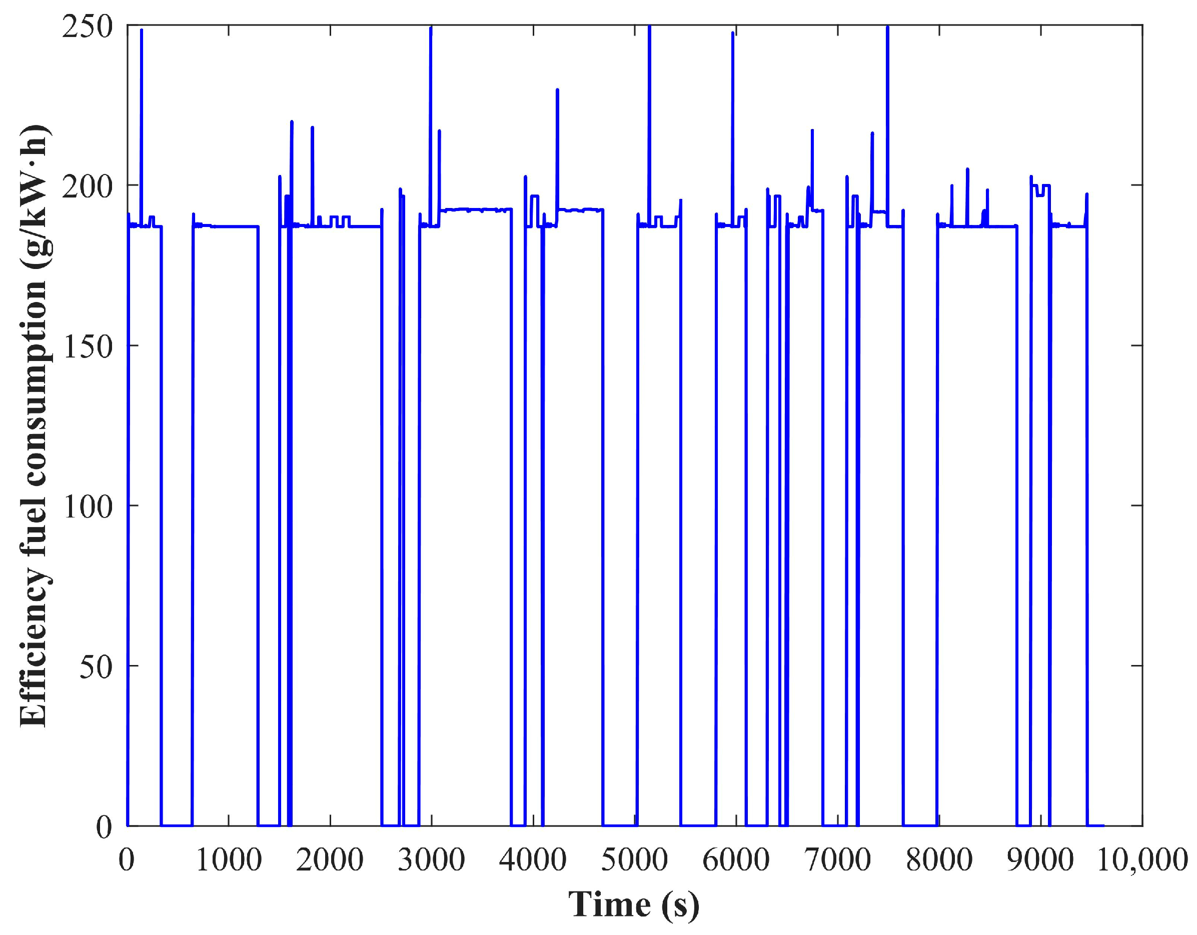
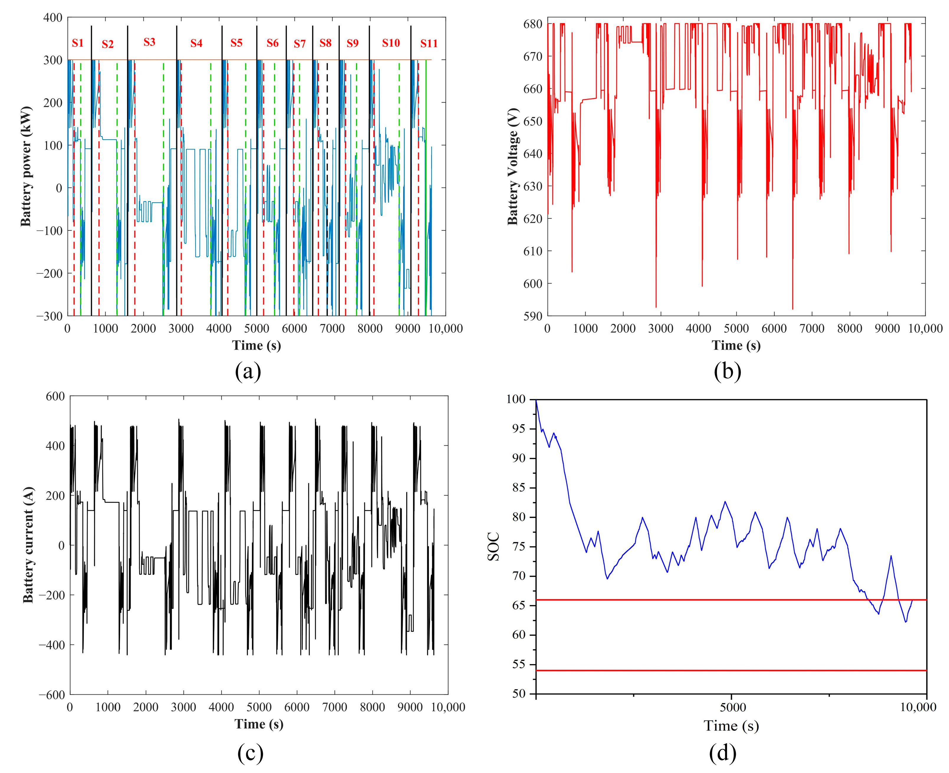
  • By creating a simulation model for the entire vehicle, it was possible to determine the battery operating state and engine fuel consumption rate of the train in each hybrid mode as well as the operating points of the engine during vehicle operation. At the end of the train operation, the battery SOC was in the balance range. The simulation verified the effectiveness of the chosen configuration.
  • Future research will examine in further detail the impact of the efficiency of power-switching elements on the various operating modes of the hybrid box, as well as the coordinated matching control between the engine and the dual motors.

Author Contributions

Conceptualization, W.L. and G.Q.; methodology, W.L. and Z.Z.; software, W.L.; validation, W.L., W.S. and G.L.; writing—original draft preparation, X.C.; writing—review and editing, W.L.; supervision, W.S.; funding acquisition, W.L. All authors have read and agreed to the published version of the manuscript.

Funding

This research was funded by the Liaoning Province to open bidding for selecting the best candidates and science and technology development special project: rail transportation equipment with hybrid power package system development and application demonstration: Grant number 2021JH1/10400073.

Institutional Review Board Statement

Not applicable.

Informed Consent Statement

Not applicable.

Data Availability Statement

The data presented in this study are available on request from the corresponding author. The industrial partner’s policy prevents public access to the data.

Acknowledgments

We would like to acknowledge all of the authors and peer reviewers for their contributions to this Special Issue. We would also like to thank the editorial board of Applied Sciences for trusting our proposal of the Special Issue and the editorial team at MDPI for the help in handling the editorial process.

Conflicts of Interest

The authors declared no potential conflicts of interest with respect to the research, authorship, and/or publication of this article.

References

  1. Boehm, M.; Arnz, M.; Winter, J. The potential of high-speed rail freight in Europe: How is a modal shift from road to rail possible for low-density high value cargo? Eur. Transp. Res. Rev. 2021, 13, 4. [Google Scholar] [CrossRef]
  2. Hanssen, T.-E.S.; Mathisen, T.A.; Jørgensen, F. Generalized Transport Costs in Intermodal Freight Transport. Procedia Soc. Behav. Sci. 2012, 54, 189–200. [Google Scholar] [CrossRef] [Green Version]
  3. Meinert, M.; Melzer, M.; Kamburow, C.; Palacin, R.; Leska, M.; Aschemann, H. Benefits of hybridisation of diesel driven rail vehicles: Energy management strategies and life-cycle costs appraisal. Appl. Energy 2015, 157, 897–904. [Google Scholar] [CrossRef]
  4. Wishart, J.; Zhou, Y.L.; Dong, Z. Review of multi-regime hybrid vehicle powertrain architecture. Int. J. Electr. Hybrid Veh. 2008, 1, 248. [Google Scholar] [CrossRef] [Green Version]
  5. Frieske, B.; Kloetzke, M.; Mauser, F. Trends in Vehicle Concept and Key Technology Development for Hybrid and Battery Electric Vehicles. World Electr. Veh. J. 2014, 6, 9–20. [Google Scholar] [CrossRef] [Green Version]
  6. Donateo, T.; Chiodo, L.S. Design and Reliability Analysis of a Series/Parallel Hybrid System with a Rotary Engine for Safer Ultralight Aviation. Appl. Sci. 2023, 13, 4155. [Google Scholar] [CrossRef]
  7. Li, Q.; Zhang, Z.; Bai, J.; Zhang, T.; Gai, F. Development of a Compound Power-split Hybrid Power System for Commercial Vehicles. Int. J. Automot. Technol. 2022, 23, 135–147. [Google Scholar] [CrossRef]
  8. Yang, Y.; Li, P.; Pei, H.; Zou, Y. Design of all-wheel-drive power-split hybrid configuration schemes based on hierarchical topology graph theory. Energy 2022, 242, 122944. [Google Scholar] [CrossRef]
  9. Zhao, Z.; Tang, P.; Li, H. Generation, Screening, and Optimization of Powertrain Configurations for Power-Split Hybrid Electric Vehicle: A Comprehensive Overview. IEEE Trans. Transp. Electrif. 2022, 8, 325–344. [Google Scholar] [CrossRef]
  10. Ho, T.-T.; Hwang, S.-J. Configuration Synthesis of Novel Hybrid Transmission Systems Using a Combination of a Ravigneaux Gear Train and a Simple Planetary Gear Train. Energies 2020, 13, 2333. [Google Scholar] [CrossRef]
  11. Li, Q.; Zhou, X.; Wang, S.; Liang, J. Power split transmission with continuously variable planetary ratio. Mech. Mach. Theory 2019, 140, 765–780. [Google Scholar] [CrossRef]
  12. Cammalleri, M.; Castellano, A. Analysis of hybrid vehicle transmissions with any number of modes and planetary gearing: Kinematics, power flows, mechanical power losses. Mech. Mach. Theory 2021, 162, 104350. [Google Scholar] [CrossRef]
  13. Hu, J.; Liu, Z.; Mei, B.; Peng, H. Optimization Design Scheme of Power-split Hybrid Electric Powertrain Configuration with Single Planetary Gear. JMechE 2021, 57, 264–276. [Google Scholar] [CrossRef]
  14. Wang, S.; Zhang, S.; Shi, D.; Sun, X.; He, J. Research on instantaneous optimal control of the hybrid electric vehicle with planetary gear sets. J. Braz. Soc. Mech. Sci. Eng. 2019, 41, 51. [Google Scholar] [CrossRef]
  15. Lin, C.H. Modeling and analysis of power trains for hybrid electric vehicles. Int. Trans. Electr. Energy Syst. 2018, 28, e2541. [Google Scholar] [CrossRef]
  16. Yang, Y.; Mi, J.; Hu, X.; Qin, D. Graph Theory Modeling and Dynamics Analysis on the Coupled Planetary Transmission System of HEV. Automot. Eng. 2015, 37, 9–15+54. [Google Scholar]
  17. Zhang, X.; Li, S.E.; Peng, H.; Sun, J. Design of Multimode Power-Split Hybrid Vehicles—A Case Study on the Voltec Powertrain System. IEEE Trans. Veh. Technol. 2016, 65, 4790–4801. [Google Scholar] [CrossRef]
  18. Ngo, H.; Yan, H. Configuration synthesis of series–parallel hybrid transmissions. Proc. Inst. Mech. Eng. Part D J. Automob. Eng. 2015, 230, 664–678. [Google Scholar] [CrossRef]
  19. Bayrak, A.E.; Ren, Y.; Papalambros, P.Y. Topology Generation for Hybrid Electric Vehicle Architecture Design. J. Mech. Des. 2016, 138, 081401. [Google Scholar] [CrossRef]
  20. Pei, H.; Hu, X.; Yang, Y.; Tang, X.; Hou, C.; Cao, D. Configuration optimization for improving fuel efficiency of power split hybrid powertrains with a single planetary gear. Appl. Energy 2018, 214, 103–116. [Google Scholar] [CrossRef]
  21. Wang, C.-L.; Yin, C.-L.; Zhang, T.; Zhu, L. Powertrain design and experiment research of a parallel hybrid electric vehicle. Int. J. Automot. Technol. 2009, 10, 589–596. [Google Scholar] [CrossRef]
  22. Dong, P.; Zuo, S.; Liu, T.; Xu, X.; Guo, W.; Liu, Y.; Wu, H.; Wang, S. A matrix-based method for searching configurations of planetary gear trains. Mech. Mach. Theory 2023, 180, 105161. [Google Scholar] [CrossRef]
Figure 1. Graphical–theoretical model.
Applsci 13 07279 g001
Figure 2. Configurations for the input split arrangement. (a,d) Motor MG2 and output shaft are connected to the sun gear; (b,e) Motor MG2 and output shaft are connected to the planetary carrier; (c,f) Motor MG2 and output shaft are connected to the gear ring.
Applsci 13 07279 g002
Figure 3. Configuration for the output split arrangement. (a,b) The engine and motor MG1 are connected to the gear ring; (c,e) The engine and motor MG1 are connected to the sun gear; (d,f) The engine and motor MG1 are connected to the planetary carrier.
Applsci 13 07279 g003
Figure 4. (a) Ratio of the electrical power to the engine power for the input; (b) ratio of the electrical power to the engine power for the output split arrangement.
Applsci 13 07279 g004
Figure 5. Acceleration time (0–100 km/h) for the feasible power-split configurations.
Applsci 13 07279 g005
Figure 6. Structure of the hybrid box corresponding to scheme b and f. (a) The structural arrangement of scheme b; (b) The structural arrangement of scheme f using clutches and brakes; (c) Scheme f with a reduced axial dimension structural arrangement using clutches.
Applsci 13 07279 g006
Figure 7. Effective engine fuel consumption rate.
Applsci 13 07279 g007
Figure 8. (a) Distribution of engine operating points of internal combustion engine trains. (b) Distribution of engine operating points of the hybrid train. (c) Distribution of the MG1 working points of the hybrid train. (d) Distribution of the MG2 working points of the hybrid train.
Applsci 13 07279 g008
Figure 9. Fuel consumption results for hybrid railways.
Applsci 13 07279 g009
Figure 10. (a) Battery power during the simulation; (b) battery voltage during the simulation; (c) battery power during the simulation; (d) battery SOC value during the simulation.
Applsci 13 07279 g010
Table 1. Physical meaning of the graphical–theoretical model.
Expression InformationExpression SymbolExpression Meaning
Planetary row partsSolid circleApplsci 13 07279 i001Planetary row elements
Hollow circleApplsci 13 07279 i002Power components and power-switching elements
ConnectionsSingle solid lineApplsci 13 07279 i003Planetary row components connected to power elements
Two-way dashed lineApplsci 13 07279 i004External planetary row gear
Single arrow solid lineApplsci 13 07279 i005Internal planetary row gear
Dotted lineApplsci 13 07279 i006Multi-connector connection (C, S, and R coaxial rotation)
Double dashed lineApplsci 13 07279 i007Single-connector connection (C and P coaxial rotation)
Two-way solid lineApplsci 13 07279 i008Connection via a power-switching element
Component levelsPlanetary wheel layerI
Solar plexus layerII
Power component layerIII
Power-switching elementsClutchApplsci 13 07279 i009
BrakeApplsci 13 07279 i010
Disclaimer/Publisher’s Note: The statements, opinions and data contained in all publications are solely those of the individual author(s) and contributor(s) and not of MDPI and/or the editor(s). MDPI and/or the editor(s) disclaim responsibility for any injury to people or property resulting from any ideas, methods, instructions or products referred to in the content.

