Article

Modification and Optimization of Cycloidal Gear Tooth Profile Based on Machining Error Compensation

College of Mechanical Engineering, Donghua University, Shanghai 201620, China
*
Author to whom correspondence should be addressed.
Appl. Sci. 2023, 13(4), 2581; https://doi.org/10.3390/app13042581
Submission received: 12 January 2023 / Revised: 14 February 2023 / Accepted: 15 February 2023 / Published: 16 February 2023
(This article belongs to the Special Issue Transmission Mechanics: From Theory to Application)

Abstract

:
The rotary vector reducer presents high precision and load capacity characteristics. The shape of the cycloidal gear tooth profile in the rotary vector reducer significantly affects its performance. Meanwhile, the effect of the machining error on the error between the designed and theoretical tooth profiles cannot be ignored. Thus, this paper analyzes the machining error items that affect the shape of the cycloidal gear profile from the machining process perspective. Due to the random characteristics and different distribution rules inherent in various machining errors, this paper proposes a cycloidal gear machining error compensation and modification model based on the Monte Carlo simulation method, providing a new theoretical method for compensating cycloidal gear machining errors. While compensating for machining errors, considering the impact of cycloidal gear modification on the carrying capacity, the NSGA-Ⅱoptimization algorithm is utilized to optimize the cycloidal gear modification parameter and finally, to solve the modification parameters with a more comprehensive performance.

1. Introduction

The rotary vector reducer (the RV reducer) is based on a precision reduction mechanism using the cycloid pinwheel planetary transmission, as shown in Figure 1. It possesses excellent characteristics, such as high transmission accuracy, extensive transmission ratio range, strong bearing capacity, and compact structure [1], and it is widely utilized for motion and torque transmission in industrial robots [2], medical equipment, aerospace applications, precision machine tools, and other fields. Ideally, although the standard cycloid pinwheel transmission is a backlash-free meshing transmission, it cannot compensate for errors caused by manufacturing, installation, and bearing deformation, which will lead to problems such as assembly difficulties, interference jamming, and extremely poor lubrication effects during actual use. Therefore, the cycloid pinwheel must be modified to improve meshing transmission. Since the pin teeth in the cycloid pinwheel transmission are cylindrical, the cycloidal gear segment is usually modified.
The tooth profile shape of the cycloidal gear significantly influences the cycloid pinwheel transmission [3,4] and also presents a technical difficulty in designing and producing RV reducers. It is of great significance to study the modification of the cycloidal gear to improve the transmission performance of the RV reducer. Malhotra et al. [5] proposed a procedure to calculate the forces on various elements of the speed reducer and their theoretical efficiency. They also studied the effects of design parameters on forces and contact stresses. Litvin et al. [6] considered the application of the cycloidal gear in some actual products and performed in-depth research on the generation and geometry of the cycloidal gear. Blanche et al. [7] modeled the machining tolerances of the cycloid drive and studied the influence of machining tolerances on backlash and torque ripple. Carlo Gorla et al. [8] verified the effect of design parameters on the force of the cycloidal gear. Sensinger et al. [9] described the sources of tolerances and their effects on backlash and torque ripple, without compensating for these effects. Thube et al. [10] used the finite element method to study the stress distribution of the rotating parts of the cycloidal reducer simulated in a dynamic environment, analyzing the stress and deformation changes with time in one cycle. Lin et al. [11] studied the kinematic error and tolerance design of cycloidal gear reducers, using the Monte Carlo method to analyze the distribution of kinematic errors and optimize the tolerance. Li et al. [12] proposed an improved load distribution model of the mismatched cycloid-pin gear pair with ring pin position deviations and demonstrated the influences of ring pin position deviations on the distributed load, contact stress, loaded transmission error, and instantaneous gear ratio of the mismatched cycloid-pin gear pair. Komorska and Grosso studied the diagnosis of problems in the cycloidal gears and cycloidal gearboxes, respectively [13,14]. Additionally, many scholars have also conducted research on cycloidal gearboxes [15,16,17,18,19]. However, the technology related to cycloidal gear modification is kept strictly confidential and blocked, and there are few published reports. The RV reducer research started late in China, and since then, many scholars have performed various studies on cycloidal gear tooth profile modification. Several modification methods have been presented in the literature, such as equidistant modification, radial movement modification, angle modification, and their combined modification [20]. Accordingly, many scholars have developed additional modification methods [21,22]. Although machining error is a critical factor affecting the actual cycloidal gear profile and theoretical profile, few related studies considered the machining error compensation. Ayadi et al. [23] divided the synthesis of machining tolerances into three steps, finally obtaining the best machining process diagram. Guo Jingbin et al. [24] measured the full tooth profile error of the cycloidal gear and converted it into the change in the modification amount through Fourier transformation, while not analyzing it from the perspective of the machining error principle. Zhang et al. [25] utilized a coordinate measuring machine to measure the tooth profile of the cycloidal gear and analyzed the machining error. However, the error analysis was not in-depth, and they did not compensate for the error. Nie Shaowen et al. [26] considered the machining error of the cycloidal tooth profile to convert the tooth profile shape change caused by the machining error into the amount of angle modification for compensation. However, the processing error value is selected based on experience, which has high technical requirements and requires many production practices to obtain more accurate parameter values, thus exhibiting a long cycle and poor adaptability. Wang Ruoyu et al. [27] established a new modification model for machining error compensation, which obtains the corresponding machining error from the actual measurement results using the regression algorithm, and then compensates for it. Compared with the empirical modification method, this modification method significantly reduces the error between the actual and ideal tooth profiles. However, this method requires an accurate measurement of the actual tooth profile, which is a complicated process. Many sampling measurements are inappropriate for this method, and the measurements must be repeated after replacing the processing equipment, which is a complicated operation.
Considering the high requirements for selecting empirical parameters and the complicated operation, this paper establishes a cycloidal tooth profile modification model using Monte Carlo simulation analysis, based on the work in previous studies. By analyzing the machining errors and verifying their item characteristics, the model employs a computer to simulate many processing errors based on the Monte Carlo simulation analysis method. Moreover, the mathematical statistics for the sampling results determine the tooth profile variation within a specific confidence range, providing a particular theory and method for analyzing the cycloidal gear machining error. Furthermore, to improve the comprehensive performance, the influence of cycloidal gear tooth profile change on the bearing capacity is comprehensively considered. However, the optimal modification parameters obtained by error compensation and the optimal modification parameters obtained by the maximum carrying capacity show a contradictory relationship. Therefore, the optimization algorithm of NSGA-II is utilized to optimize these parameters, and the modified parameters with better comprehensive performance are obtained.
Figure 2 shows the structure of the paper. Section 2 theoretically analyzes the machining error of the cycloidal gear, including machining error analysis (Section 2.1), machining error compensation (Section 2.2), and sensitivity analysis of the machining error (Section 2.3). Section 3 mainly introduces the Monte Carlo simulation method, specifically including the Monte Carlo simulation steps (Section 3.1), the acquisition of the sampling formula for each machining error item (Section 3.2), and the case analysis (Section 3.3). Section 4 mainly introduces the optimization of the cycloidal gear modification parameters, mainly including the establishment of optimization models (Section 4.1), the establishment of objective function (Section 4.2), the selection of design variables (Section 4.3), constraints (Section 4.4), and final optimization results (Section 4.5).

2. Theoretical Analysis of Machining Error

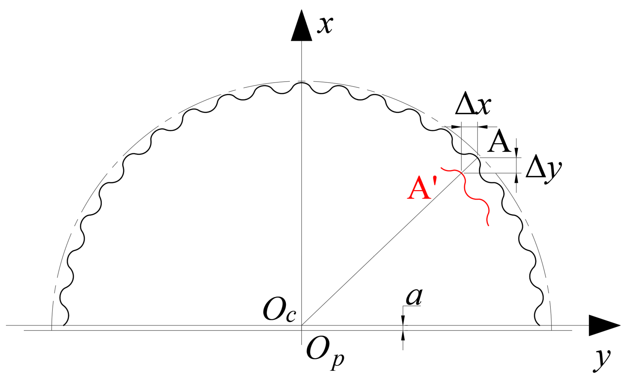
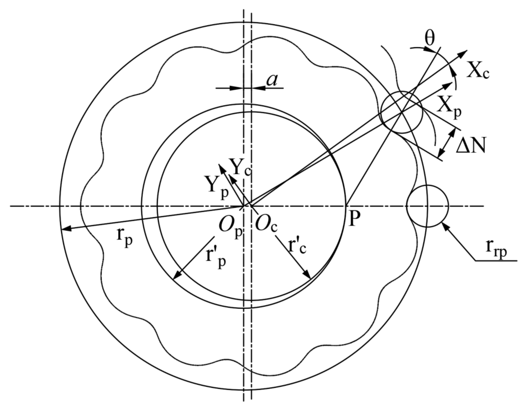
2.1. Machining Error Analysis

Equipment errors cause machining errors during processing. The cycloidal gear is processed by the generation method, as shown in Figure 3. During processing, the grinding wheel only performs the high-speed rotary cutting motion, and the crankshaft drives the workpiece to perform revolutions around the crankshaft. Additionally, it is driven by the machine tool’s transmission system in the spindle box to perform reverse rotation around the workpiece axis. The primary sources of machining errors in this process are the grinding wheel radius error, the distance error from the grinding wheel center to the spindle center, the eccentricity error of the machine tool spindle, the transmission ratio error of the machine tool, and the eccentricity error of the installation of the cycloidal gear blank [28].

2.2. Machining Error Compensation

The cycloidal gear mathematical model can facilitate the quantitative analysis of the cycloidal gear. The standard cycloidal gear profile equation is given as follows [13]:
x = ( r p r r p S 0.5 ) cos ( 1 i H ) φ ( a K 1 r r p S 0.5 ) cos i H φ y = ( r p r r p S 0.5 ) sin ( 1 i H ) φ + ( a K 1 r r p S 0.5 ) sin i H φ
where r p is the radius of the center circle of the pin tooth (mm), r r p is the radius of the pin tooth (mm), i H is the relative transmission ratio of the cycloidal gear and the pin wheel, φ is the rotation angle of the rotating arm O p O c ¯ relative to the center of a specific pin tooth (rad) (as shown in Figure 4), a is the eccentric distance of the center of the cycloidal gear relative to the center of the pin tooth center circle (mm), K 1 is the curtate ratio (the ratio of short epicycloid amplitude to epicycloid amplitude and K 1 = r p / r p = a z p / r p ), and S = 1 + K 1 2 2 K 1   c o s φ .
Figure 5 shows the tooth profile variation caused by the grinding wheel radius error during the cycloidal gear machining process. Since, in principle, the change of the grinding wheel grinding radius error is similar to the change of the pin tooth radius, the pin tooth radius in the x and y directions is differentiated to obtain the coefficients k 1 x and k 1 y of the variation of the cycloidal gear profile in the x and y directions caused by the grinding wheel grinding radius error, as shown in Formula (2). Similarly, the error items, such as the distance error from the center of the grinding wheel to the center of the spindle center, the eccentricity error of the machine tool spindle, the transmission ratio error of the machine tool, and the eccentricity error of the installation of the cycloidal gear blank, are differentiated to obtain the variation coefficients of each error item on the x and y axes, as shown in Table 1.
k 1 x = x r r p = { K 1 cos ( i H φ ) cos [ ( 1 i H ) φ ] } S 0.5 k 1 y = y r r p = { K 1 sin ( i H φ ) sin [ ( 1 i H ) φ ] } S 0.5
where α = ( 1 i H ) φ , β = i H φ , T i = K i cos φ , and λ = r r p / r p .
Since these errors are small, their superposition can be linearly approximated. The comprehensive variation of the cycloidal tooth profile is equal to the sum of each variation as shown in Figure 6; that is:
g x ( φ , ξ ) = Δ x = k 1 x ξ 1 + k 2 x ξ 2 + k 3 x ξ 3 + k 4 x ξ 4 + k 5 x ξ 5 g y ( φ , ξ ) = Δ y = k 1 y ξ 1 + k 2 y ξ 2 + k 3 y ξ 3 + k 4 y ξ 4 + k 5 y ξ 5
The coordinate equation of the cycloidal gear profile after compensation is obtained by combining Formulas (1)~(3) and related formulas in Table 1.
x 2 = ( r p r r p S 0.5 ) cos ( 1 i H ) φ ( a K 1 r r p S 0.5 ) cos i H φ g x ( φ , ξ ) y 2 = ( r p r r p S 0.5 ) sin ( 1 i H ) φ + ( a K 1 r r p S 0.5 ) sin i H φ g y ( φ , ξ )

2.3. Sensitivity Analysis

The sensitivity analysis aims to analyze the influence of the change rate of various machining errors on the variation of the cycloidal gear profile. It expresses the different degrees of influence and the changing rules of each machining error on the variation of the cycloidal gear profile. Accordingly, the most sensitive error item can be obtained, and the numerical method can perform a sensitivity analysis on each error term. Assuming the machining errors e = [ e 1 , e 2 , e 3 , e 4 , e 5 ] that affect the cycloidal gear profile as the design variables, the function f ( e ) = f ( e 1 , e 2 , e 3 , e 4 , e 5 ) is the normal variation of the cycloidal gear profile, and the sensitivity of the design variables corresponding to this function is:
f = [ f e 1 , f e 2 , f e 3 , f e 4 , f e 5 ]
As shown in Figure 7, the variation of the cycloidal tooth profile caused by the machining error in the x and y directions is converted into the variation in the normal direction of the cycloid through the geometric relationship [29], which can facilitate the comparison of sensitivities, namely:
Δ N = Δ X cos θ + Δ Y sin θ
where cos θ = [ K 1 cos i H φ cos ( 1 i H ) φ ] S 1 / 2 , sin θ = [ K 1 cos i H φ + cos ( 1 i H ) φ ] S 1 / 2 .
Similarly, the variation coefficients in the x and y directions are converted into those in the normal direction; that is, the sensitivity coefficients of each processing error item, as shown in the following formula:
k N = k x cos θ + k y sin θ
The design parameters of the RV reducer cycloidal gear used in this paper are shown in Table 2. These parameters are the parameters of the Nabtesco model RV-40E reducer.
Table 3 shows the variation range of each machining error item. The data in Table 3 comes from the work of references [27,30], and fine-tuning is carried out on this basis; the information is not from the experimental data.
In summary, the sensitivity of the cycloidal gear profile to each machining error item can be obtained, as shown in Figure 8. Figure 8 shows that the transmission ratio error of the machine tool has the maximum influence on the variation in the cycloidal gear profile.

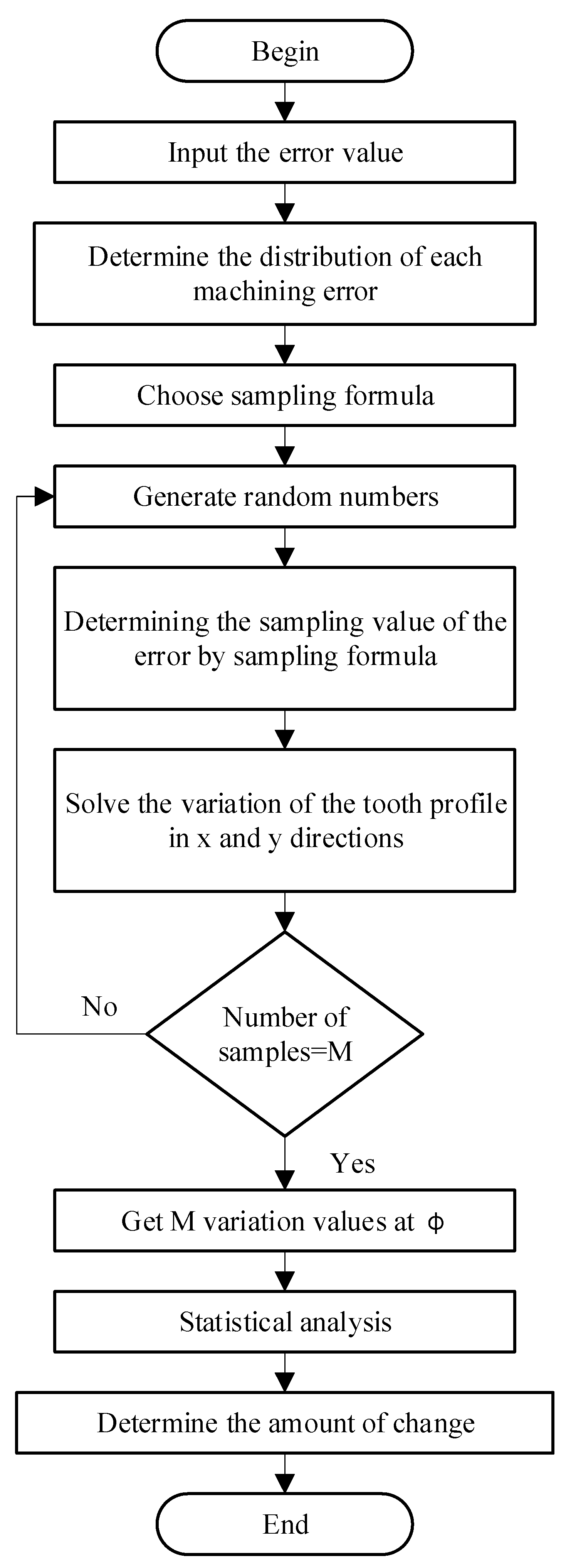
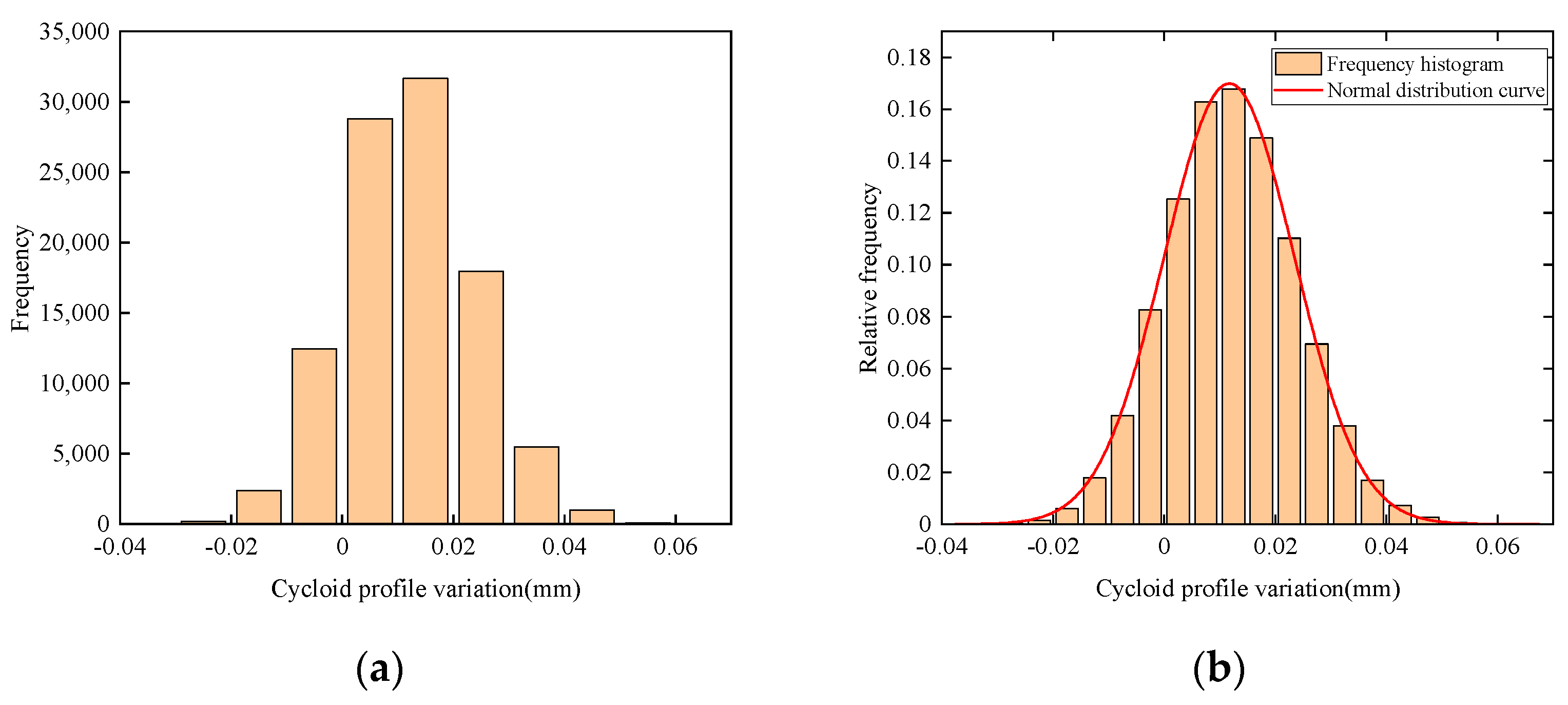
3. Monte Carlo Simulation

The Monte Carlo method [31] is also called the random simulation method, or the random sampling technique. This method establishes a probability model, or a random process whose parameters equal the problem solution. Then, the statistical characteristics of the parameters are calculated through the sampling test of the model. Finally, the approximate value of the solution is given.

3.1. Simulation Steps

The simulation steps of the cycloidal gear machining error analysis using the Monte Carlo method are shown in Figure 9. First, it is necessary to determine each machining error item, its probability distribution, and the distribution parameters, establishing the sampling formula according to different probability distributions. The MATLAB software is then utilized to generate a random number and obtain the sampling value for each machining error item through the sampling formula. Finally, according to the calculation method of the previously mentioned tooth profile variation, the tooth profile variation in the x and y directions of each sample is obtained. The simulation process is repeated. The more the simulation process is repeated, the higher the reliability of the simulation results.

3.2. The Sampling Formula of Each Machining Error Item
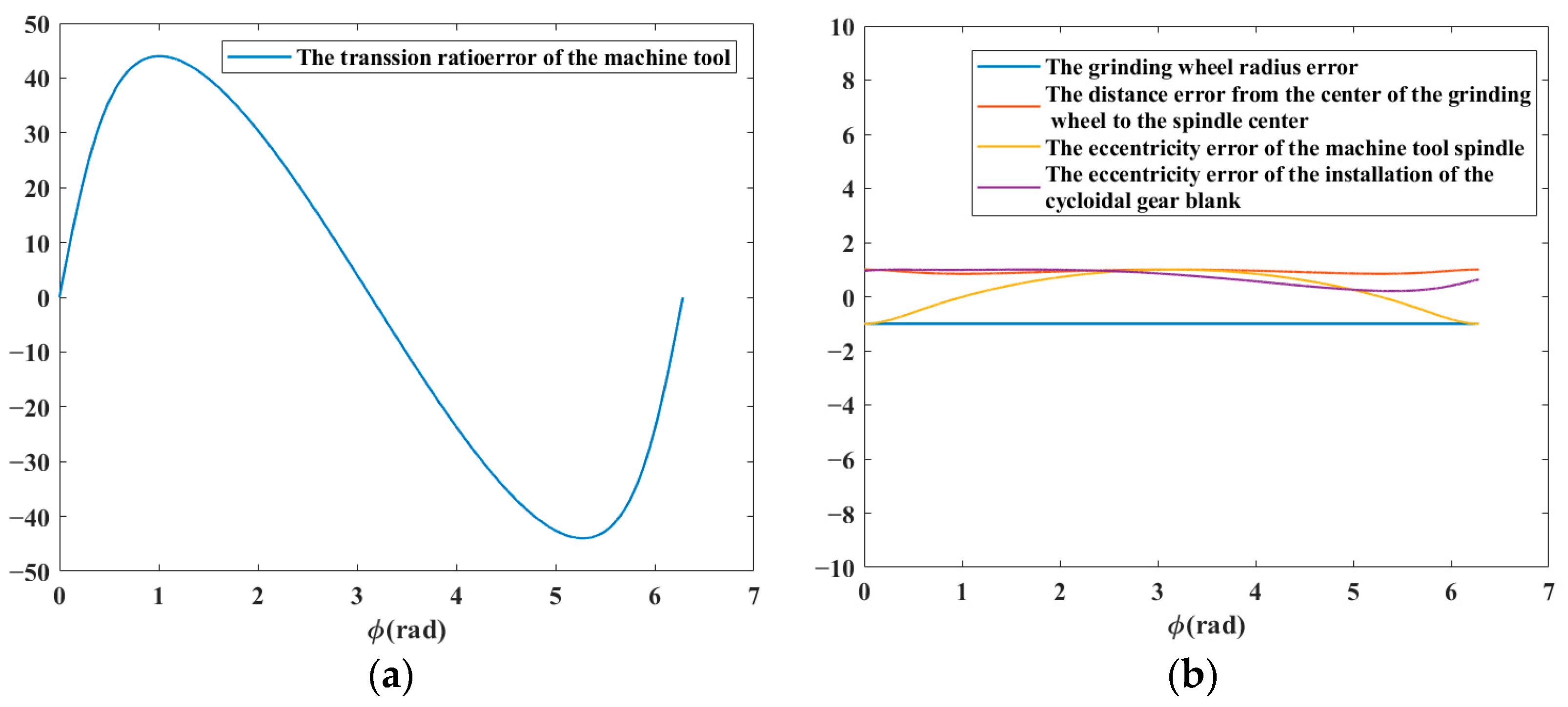
(1) The grinding wheel radius error, the distance error from the grinding wheel center to the spindle center, the eccentricity error of the machine tool spindle, the transmission ratio error of the machine tool, and other errors obey the normal distribution, and its probability density function [32] is shown in Formula (8). Even if the variance σ in Formula (8) is small, large negative values for the error are still possible (albeit with low probability), thus, assuming a Gaussian distribution, is at best, a convenient approximation.
f ( x ) = 1 2 π σ e 1 2 ( x μ σ ) 2 , ( < x < + )
where µ and σ are the mean and standard deviation in a normal distribution (mm), respectively.
The sampling of normal distribution X, obtained by transformed sampling [33], is shown in Formula (9), where R 1 , R 2 are uniform distributions ranging from 0 to 1. The 3 σ principle is suitable for the data processing of samples with a sufficiently large number of normal or approximately normal distributions. An interval is determined according to a certain probability, and it is considered that any error exceeding this interval is not a random error, but a gross error, and the data containing this error should be eliminated. When the confidence level is 99.7%, according to the 3 σ principle, the value of the distribution parameter is shown in Formula (10), where T = T 1 T 2 , T = T 1 + T 2 , where T 1 and T 2 are the values within the error range, respectively.
X = μ + σ ( 2 ln R 1 ) 1 / 2 sin ( 2 π R 2 )
μ = 1 2 T , σ = 1 6 T
(2) Since the eccentric error is composed of two independent random variables of magnitude and direction [34], the eccentricity error of the installation of the cycloidal gear blank obeys the Rayleigh distribution, and its distribution and probability density functions are shown in Formulas (11) and (12), respectively:
F ( X ) = 1 e 1 2 ( X η ) 2 , ( X > 0 )
f ( X ) = X η 2 e X 2 2 η 2 , ( X > 0 )
The sampling formula obtained by the direct sampling method is:
R = 1 e 1 2 ( X η ) 2
where R represents a uniform distribution ranging from 0 to 1. According to the probability distribution relationship, since R and 1 − R have the same probability distribution, the sampling formula of X, which obeys the Rayleigh distribution, can be obtained from Formula (14). When the confidence level is 99.7%, the distribution parameter values can be obtained from (15).
X = η ( 2 ln R ) 1 / 2
η = T 2 2 ln ( 1 0.997 ) = T 6.8
(3) Due to the rotary motion, the phase angles of the cycloidal gear and each runout amount obey the uniform distribution within 0 to 2 π , with the following probability density formula:
f ( θ ) = 1 2 π , ( 0 θ 2 π )
The sampling formula of the uniform distribution θ obtained by the direct sampling method is shown in Formula (17), where R is a uniform distribution from 0 to 1,
θ = 2 π R

3.3. Case Analysis

In the Monte Carlo method, specific differences can be observed in the results of each simulation sampling, indicating the random characteristics of actual machining errors. In order to ensure the accuracy of the Monte Carlo simulation of tooth profile variation caused by machining errors, it is necessary to perform multiple simulations and statistical analyses on the obtained data. A total of 100,000 cycloidal gears were simulated and processed in MATLAB using the Monte Carlo simulation method, and the distribution of tooth profile variation caused by machining errors was obtained, as shown in Figure 10. The average tooth profile variation of 100,000 randomly-produced cycloidal gears is 0.012067 mm, and the variance is 0.000145 mm, which shows that the variation distribution is relatively concentrated, and the model is reasonable. The confidence interval of the tooth profile variation simulation is [ 0.011953 , 0.012103 ] , which shows that 99.7% of the tooth profile variation caused by machining errors is distributed within the confidence interval in the 100,000 simulation statistics, demonstrating the accuracy of the statistical results.
The Kolmogorov–Smirnov method is utilized for normality testing, and the results of H = 0, p-value = 0.7383 > 0.05 are obtained, showing that the distribution in Figure 10b follows a normal distribution.

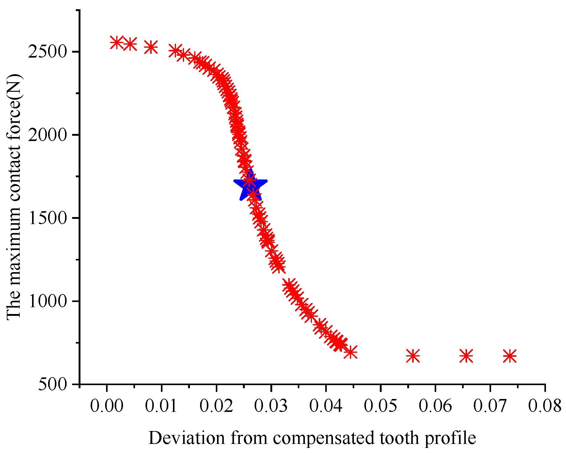
4. Modifying the Parameter Optimization

4.1. Optimization Model

(1) Machining error compensation model
The machining error is analyzed to obtain the coordinate equation for the tooth profile of the cycloidal gear after compensating for the machining error, as shown in Formula (4). The coordinate equation of the tooth profile of the cycloidal gear after the combined modification of equidistant and radial movement modification can be obtained as follows [35]:
x 3 = [ r p r r p S 0.5 ] cos ( 1 i H ) φ a r p [ r p z p r r p S 0.5 ] cos i H φ y 3 = [ r p r r p S 0.5 ] sin ( 1 i H ) φ + a r p [ r p z p r r p S 0.5 ] sin i H φ
where r p = r p + Δ r p ,   r r p = r r p + Δ r r p .
The curve modified by equidistant and radial movement modification cannot completely coincide with the compensated tooth profile, and there is a specific deviation. When φ turns 2 π , a complete cycloidal gear tooth can be formed. For example, the interval [ 0 , 2 π ] is divided into m 1 equal parts. After error compensation, the tooth profile coordinates ( x 2 i , y 2 i ) ( i = 1 , 2 , m ) of the cycloidal gear can be obtained according to Formula (4). At the same time, the tooth profile coordinates ( x 3 i , y 3 i ) ( i = 1 , 2 , m ) of the cycloidal gear after the combined modification of equidistant and radial movement can be obtained from (18). There is a specific deviation between the coordinates of the two tooth profiles, in which its degree can be measured by the average value of the deviation of m points, as shown in Formula (19). The smaller the deviation degree, the higher the fitting degree.
D ( Δ r p , Δ r r p ) = 1 m i = 1 m ( x 3 i x 2 i ) 2 ( y 3 i y 2 i ) 2
(2) Carrying model
After modifying the cycloidal gear by the combined modification of equidistant and radial movement, the multi-teeth meshing condition no longer exists without considering the elastic deformation of the cycloidal pin wheel. However, when a certain pair of cycloidal gear teeth come into contact, there are different degrees of initial normal backlash between other cycloidal gear teeth. As shown in Formula (20) [36], the initial normal backlash in the normal direction of the i-th pair of cycloidal gears and the pin teeth caused by equidistant modification and radial movement modification is:
Δ ( φ ) i = Δ r r p ( 1 sin φ i S 1 / 2 ) Δ r p ( 1 K 1 cos φ i ( 1 K 1 2 ) 1 / 2 sin φ i ) S 1 / 2
The loaded tooth surface will undergo different degrees of elastic deformation during transmission. In the RV transmission, since the pin teeth are half buried in the pin holes of the pin gear housing, there is no bending deformation, and elastic deformation mainly considers contact deformation. Therefore, the total deformation comprises the contact deformation between the cycloidal gear teeth and the pin teeth, and between the pin teeth and the pin gear housing. According to the RV transmission characteristics, the deformation of the two parts is produced simultaneously under the same meshing force, the contact between the cycloidal gear and the pin wheel satisfies the Hertzian contact, and the maximum deformation δ max can be obtained from the Hertzian contact formula [37] as:
δ max = 2 F max π b [ 1 μ 1 2 E 1 ( 1 3 + ln 4 ρ c ) + 1 μ 2 2 E 2 ( 1 3 + ln 4 r r p c ) ]
where E is the modulus of elasticity, μ is Poisson’s ratio, and ρ is the radius of curvature.
In the loaded state, the cycloidal gear and the pin teeth produce multi-teeth meshing due to elastic deformation. In this state, there will be multiple meshing points. The deformation amount is different for pin teeth at different positions of the meshing point, and the deformation amount of the meshing point can be obtained according to Formula (22). When the load deformation between the cycloidal gear and the pin teeth is greater than their initial meshing clearance, the pairing of the cycloidal gear and the pin teeth will enter meshing; otherwise, they will not participate in meshing. According to this principle, the evaluation of the number of meshing teeth of the cycloidal gear and the pin teeth can be performed simultaneously.
δ i = l i β = l i δ max l max ( i = 1 , 2 , , z p / 2 )
where l is the distance from the common normal of the meshing point to the center of the cycloidal gear; under the action of load, the cycloidal gear and the pin wheel will produce contact deformation, and the cycloidal gear will turn through the β angle; assuming that the maximum deformation of the pair of cycloidal gears and the pin teeth under the largest load is δ max , the distance between the common normal of the meshing point and the center of the cycloidal gear is l max , and obviously, β = δ max / l max .
For the cycloidal gears and pin teeth, (m~n) refers to all the teeth between the m-th tooth and the n-th tooth that are in a simultaneous meshing state; because the number of meshing teeth of the modified cycloidal gear cannot reach half the number of teeth at the same time, and a certain initial gap between the modified cycloidal gear and the pin teeth in the normal direction of the meshing point Δ ( φ ) i exists, the force F i of the i-th tooth is proportional to the difference between the deformation and the initial gap [38]; that is:
F i = δ i Δ ( φ ) i δ max F max
The torque T c on the cycloidal gear is transmitted by all the cycloidal gear teeth simultaneously participating in the meshing. According to the torque balance condition, we have:
T c = i = m i = n F i l i F max = T c i = m i = n ( l i r c Δ ( φ ) i δ max ) l i
The above solution process shows that δ max is required to solve F max , and F max should be determined to solve δ max . Thus, the iterative calculation method is utilized to solve the problem. An initial value F max 0 of F max is given, and the initial value δ max 0 of δ max can be solved. Finally, the exact value of F max can be solved by Formula F max = ( F max k + F max ( k 1 ) ) / 2 . In the RV transmission, the smaller the maximum normal contact force F max , the greater the carrying capacity of the RV reducer, while considering the other parameters unchanged.

4.2. Objective Function

After error compensation, the cycloidal tooth profile is approximated by the combined modification method of equidistant and radial movement, and the influence of modification of the carrying capacity is considered simultaneously. Thus, the minimum deviation degree D ( Δ r p , Δ r r p ) and the minimum value of the maximum contact force F max of the cycloidal gear are selected as the objective function, namely:
G = [ min [ D ( Δ r p , Δ r r p ) ] , min ( F max ) ]

4.3. Design Variable

Since D ( Δ r p , Δ r r p ) and F max are functions related to Δ r r p and Δ r p , the equidistant modification amount Δ r r p and the radial movement modification amount Δ r p are selected as design variables, namely:
V = [ V 1 V 2 ] = [ Δ r r p Δ r p ]

4.4. Restrictions

(1) Curtate ratio
The curtate ratio is crucial in cycloidal pinwheel transmission. Under the constant values of the pin wheel radius and the number of teeth, the curtate ratio will affect the carrying capacity of the cycloidal gear. According to the recommended value of the curtate ratio [39], when the number of cycloidal teeth z c is 25 ~ 59 , the curtate ratio should be 0.65 ~ 0.9 .
(2) Backlash
As the input shaft rotates in the opposite direction, the output shaft lags behind the input shaft in transmission, generating backlash. The backlash is an essential indicator affecting the accuracy of RV transmission, so it should be constrained. The backlash caused by equidistant and radial movement modification can be calculated according to Formula (28) [40]. In this paper, the designed backlash value Δ φ is less than 0.2.
Δ φ = 2 Δ r r p a z c 2 Δ r p a z c 1 K 1 2
(3) Radial clearance
In order to compensate for errors and facilitate assembly and lubrication, a specific radial clearance must be retained. A radial clearance that is too large will reduce the transmission accuracy of the reducer. In contrast, a small radial clearance cannot compensate for the error and meet the lubrication requirements, so the radial clearance Δ r must be constrained. For the combined modification of equidistant and radial movement, the radial clearance can be numerically calculated as Δ r = Δ r r p Δ r p [41]. This paper takes the radial clearance as 0.02 mm.

4.5. The Optimization Algorithm and Results

Traditional multi-objective optimization mainly converts the weighted sum of each objective into a single-objective problem. This method has the disadvantages of high subjectivity, the inconsistency of units among objects of different properties, and the difficulty in comparison [42]. This paper utilizes the NSGA-II optimization algorithm to solve the multi-objective optimization. NSGA-II is a multi-objective optimization algorithm improved based on the NSGA algorithm, possessing the advantages of low computational complexity and highly precise optimization results. Unlike a single-objective problem, the results of multi-objective optimization are multiple sets of solutions, also known as Pareto optimal solutions. An optimization algorithm program is written in MATLAB to solve this, and the optimized Pareto front is shown in Figure 11. As revealed in Figure 11, the solution distribution is relatively uniform, while there is a conflict between the two optimization objectives designed in this paper. Moreover, there is a restrictive relationship between the fitting degree and the carrying capacity, and it is challenging to simultaneously determine the optimal solution of the two. In order to improve the comprehensive performance, the equidistant modification amount of Δ r r p = 0.1311 mm and the radial movement modification amount of Δ r p = 0.1111 mm are selected as the final optimization results, as shown in the five-pointed star in Figure 11.
The existence conditions of the anti-bow tooth profile are: (1) modified by the combined modification method of positive equidistant and positive radial movement; (2) the parameter relationship Δ r r p > Δ r r p = ( Δ r r p Δ r p ) / [ 1 ( 1 K 1 2 ) 1 / 2 ] is satisfied. The anti-bow tooth profile can effectively reduce the maximum contact force and contact stress, thereby improving the carrying capacity of the tooth surface [20]. It can be seen that the modification amount meets the existence conditions of the anti-bow tooth profile, with good carrying performance.

5. Conclusions

Machining error is an inevitable but non-negligible aspect in the design process of an RV reducer cycloidal gear. This paper quantitatively analyzes the influence of the machining error on the tooth profile of the cycloidal gear. Considering the randomness of machining errors, several computer simulations of machining errors are performed based on the Monte Carlo method. After simulation, mathematical statistics are derived based on the simulated sampling data. The variation in the cycloidal gear profile caused by the machining error is obtained. The variance of the statistical result is obtained from the statistics as 0.000145 mm2, demonstrating the particular feasibility of the model. The tooth profile after machining error compensation is fitted by the combined modification method of equidistant and radial movement, and an optimization model of error compensation is established. At the same time, the carrying capacity optimization model is established, considering the carrying capacity of the RV reducer. The multi-objective optimization algorithm of NSGA-II is utilized to optimize the models, and the equidistant modification amount of Δ r r p = 0.1311 mm and the radial movement modification amount of Δ r p = 0.1111 mm can be obtained. These optimizations meet the existence conditions of the anti-bow tooth profile, and show good carrying capacity and error compensation effects.
There are still some deficiencies in this paper, which will serve as the direction for future work: (1) The machining errors in this paper do not come from actual machine tools. Thus, the machining errors of the actual machine tools will be adopted in the future; (2) The modification parameters obtained by the proposed method have not been verified by experiments. The proposed method will be employed to process cycloidal gears and conduct experiments with RV reducers to evaluate the modification effect; (3) Errors caused by part fixture and part defects and the influence of dispersion will be considered in the future.

Author Contributions

Conceptualization, H.L.; methodology, H.L. and J.W.; theoretical analysis, H.L. and J.W.; validation, H.L. and J.W.; writing—original draft preparation, J.W.; writing—review and editing, H.L.; funding acquisition, H.L. All authors have read and agreed to the published version of the manuscript.

Funding

This research was funded by the Natural Science Foundation of Shanghai, grant number 20ZR1401300, and the Interdisciplinary Program Project of Donghua University (202212).

Institutional Review Board Statement

Not applicable.

Informed Consent Statement

Not applicable.

Data Availability Statement

Not applicable.

Conflicts of Interest

The authors declare no conflict of interest.

References

  1. Shin, J.-H.; Kwon, S.-M. On the lobe profile design in a cycloid reducer using instant velocity center. Mech. Mach. Theory 2005, 41, 596–616. [Google Scholar] [CrossRef]
  2. Erdős, G.; Kovács, A.; Váncza, J. Optimized joint motion planning for redundant industrial robots. CIRP Ann. 2016, 65, 451–454. [Google Scholar] [CrossRef] [Green Version]
  3. He, W.; Shan, L. Research and Analysis on Transmission Error of RV Reducer Used in Robot; Bai, S., Ceccarelli, M., Eds.; Springer International Publishing: Cham, Switzerland, 2015; pp. 231–238. [Google Scholar]
  4. Neagoe, M.; Diaconescu, D.; Pascale, L.; Săulescu, R. On the efficiency of a cycloidal planetary reducer with a modified structure. In Proceedings of the International Conference on Economic Engineering and Manufacturing Systems ICEEMS, Braşov, Romania, 25–26 October 2007; pp. 544–549. [Google Scholar]
  5. Malhotra, S.K.; Parameswaran, M.A. Analysis of a cycloid speed reducer. Mech. Mach. Theory 1983, 18, 491–499. [Google Scholar] [CrossRef]
  6. Litvin, F.L.; Feng, P.-H. Computerized design and generation of cycloidal gearings. Mech. Mach. Theory 1996, 31, 891–911. [Google Scholar] [CrossRef]
  7. Blanche, J.G.; Yang, D.C.H. Cycloid Drives with Machining Tolerances. J. Mech. Trans. Autom. 1989, 111, 337–344. [Google Scholar] [CrossRef]
  8. Gorla, C.; Davoli, P.; Rosa, F.; Longoni, C.; Chiozzi, F.; Samarani, A. Theoretical and Experimental Analysis of a Cycloidal Speed Reducer. J. Mech. Des. 2008, 130, 112604. [Google Scholar] [CrossRef]
  9. Sensinger, J.W. Unified Approach to Cycloid Drive Profile, Stress, and Efficiency Optimization. J. Mech. Des. 2010, 132, 024503. [Google Scholar] [CrossRef]
  10. Thube, S.V.; Bobak, T.R. Dynamic analysis of a cycloidal gearbox using finite element method. AGMA Tech. Pap. 2012, 1–13. [Google Scholar]
  11. Lin, K.-S.; Chan, K.-Y.; Lee, J.-J. Kinematic error analysis and tolerance allocation of cycloidal gear reducers. Mech. Mach. Theory 2018, 124, 73–91. [Google Scholar] [CrossRef]
  12. Li, X.; Tang, L.; He, H.; Sun, L. Design and Load Distribution Analysis of the Mismatched Cycloid-Pin Gear Pair in RV Speed Reducers. Machines 2022, 10, 672. [Google Scholar] [CrossRef]
  13. Komorska, I.; Olejarczyk, K.; Puchalski, A.; Wikło, M.; Wołczyński, Z. Fault Diagnosing of Cycloidal Gear Reducer Using Statistical Features of Vibration Signal and Multifractal Spectra. Sensors 2023, 23, 1645. [Google Scholar] [CrossRef]
  14. Grosso, P.; Massaccesi, G.; Cavalaglio Camargo Molano, J.; Mottola, G.; Borghi, D. Signal model of a cycloidal drive for diagnostic purposes. In Proceedings of the ISMA2022—USD2022, Leuven, Belgium, 12–14 September 2022. [Google Scholar]
  15. Bechhoefer, E. Condition monitoring of a cycloid gearbox. In Proceedings of the MFPT, Where Theory Meets Practice, Philadelphia, PA, USA, 17 May 2019. [Google Scholar]
  16. Bechhoefer, E. Automated Condition Monitoring of a Cycloid Gearbox. In Maintenance Management—Current Challenges, New Developments, and Future Directions; Germano, L.-T., Erik Leandro, B., Levy Ely, O., Eds.; IntechOpen: Rijeka, Croatia, 2022; p. 14. [Google Scholar]
  17. Król, R. Analysis of the backlash in the single stage cycloidal gearbox. Arch. Civ. Mech. Eng. 2022, 69, 1–19. [Google Scholar]
  18. Šlapák, V.; Ivan, J.; Kyslan, K.; Hric, M.; Ďurovský, F.; Paulišin, D.; Kočiško, M. Measurement and Modelling of a Cycloidal Gearbox in Actuator with Permanent Magnet Synchronous Machine. Machines 2022, 10, 344. [Google Scholar] [CrossRef]
  19. Amin Al Hajj, M.; Quaglia, G.; Schulz, I. Condition-Based Monitoring on High-Precision Gearbox for Robotic Applications. Shock Vib. 2022, 2022, 6653723. [Google Scholar] [CrossRef]
  20. Guan, T.; Zhang, D. Inverse Arch-shaped Teeth Profile and Its Optimization in A Cycloid Drive. J. Mech. Eng. 2005, 41, 151–156. [Google Scholar] [CrossRef]
  21. Li, T.; An, X.; Deng, X.; Li, J.; Li, Y. A New Tooth Profile Modification Method of Cycloidal Gears in Precision Reducers for Robots. Appl. Sci. 2020, 10, 1266. [Google Scholar] [CrossRef] [Green Version]
  22. Ren, Z.; Mao, S.; Guo, W.; Guo, Z. Tooth modification and dynamic performance of the cycloidal drive. Mech. Syst. Signal Process. 2017, 85, 857–866. [Google Scholar] [CrossRef]
  23. Ayadi, B.; Ben Said, L.; Boujelbene, M.; Betrouni, S.A. Three-Dimensional Synthesis of Manufacturing Tolerances Based on Analysis Using the Ascending Approach. Mathematics 2022, 10, 203. [Google Scholar] [CrossRef]
  24. Guo, J.; Wang, X.; Liu, H.; Li, Z. Measurement of Cycloidal Gear Error and Calculation of Modification. J. Tianjin Univ. 2011, 44, 85–89. [Google Scholar]
  25. Zhang, Y.; Zhu, G. Accuracy measuring for the RV reducer cycloid gear and manufacturing error analysis. In Proceedings of the International Conference on Advances in Mechanical Engineering and Industrial Informatics, Hangzhou, China, 9–10 April 2016. [Google Scholar]
  26. Shaowen, N.; Jiquan, H.; Bo, L.; Dingfang, C.; Jie, M.; Junfeng, W. The Modification Optimization Analysis of Cycloid Pin Gear Tooth Profile of RV Reducer. Mach. Des. Res. 2016, 32, 49–52. [Google Scholar]
  27. Wang, R.; Gao, F.; Liu, T. Study on Modification and Compensation of Tooth Profile of RV Reducer Cycloidal Gear. Chin. J. Sci. Instrum. 2018, 39, 81–88. [Google Scholar]
  28. Li, Z. Research on Cycloidal Gear Error. J. Mech. Transm. 1992, 24–28. [Google Scholar] [CrossRef]
  29. Zhai, H.; Bi, F.; Chen, L.; Li, Z. Study on Machining Error of Cycloidal Grinding Gear. J. Mech. Transm. 1998, 21–23. [Google Scholar]
  30. Fang, S.; Liu, Y.; Wang, H.; Taguchi, T.; Takeda, R. Research on the compensation method for the measurement error of cycloidal gear tooth flank. Int. J. Precis. Eng. Manuf. 2014, 15, 2065–2069. [Google Scholar] [CrossRef]
  31. Dubi, A. Monte Carlo Applications in Systems Engineering; Wiley: Hoboken, NJ, USA, 2000. [Google Scholar]
  32. Ross, S. A First Course in Probability; Pearson: London, UK, 2010. [Google Scholar]
  33. Yuan, G.; Wang, P. Monte Carlo Simulation and Its Application in Tolerance Design. J. Tianjin Univ. Sci. Technol. 2008, 23, 60–64. [Google Scholar]
  34. Wu, S. Research on Optimization and Experimental Validation of the Transmission of Precision Cycloidal Reduction. Doctoral Dissertation, Dalian Jiaotong University, Dalian, China, 2019. [Google Scholar]
  35. Jiao, W.; Kong, Q.; Song, D.; Liu, J.; Shen, Q. Establishment and Simulation on Mathematical Model for Modifying the Tooth Profile of Cycloid Pin-wheel. J. Mach. Des. 2008, 25, 12–14. [Google Scholar]
  36. Bangchun, W. Mechanical Design Handbook, 5th ed.; China Machine Press: Beijing, China, 2010; Volume 2. [Google Scholar]
  37. Kim, K.-H.; Lee, C.-S.; Ahn, H.-J. Torsional Rigidity of a Cycloid Drive Considering Finite Bearing and Hertz Contact Stiffness. In Proceedings of the ASME 2009 International Design Engineering Technical Conferences and Computers and Information in Engineering Conference, San Diego, CA, USA, 30 August–2 September 2009; pp. 125–130. [Google Scholar]
  38. Wei, B.; Wang, J.; Zhou, G.; Yang, R.; Zhou, H.; He, T. Mixed lubrication analysis of modified cycloidal gear used in the RV reducer. Proc. Inst. Mech. Eng. Part J J. Eng. Tribol. 2016, 230, 121–134. [Google Scholar]
  39. Wang, J.; Luo, S.; Su, D. Multi-objective optimal design of cycloid speed reducer based on genetic algorithm. Mech. Mach. Theory 2016, 102, 135–148. [Google Scholar] [CrossRef]
  40. Lu, L.; Zhang, F.; Wan, Z.; Tang, Y. Cycloidal Gear Tooth Profile Modification of RV Reducer Based on Backlash Optimization. J. S. China Univ. Technol. Nat. Sci. 2018, 46, 1–8. [Google Scholar]
  41. Wang, Q.; Qin, Z.; Zhao, D.; Wang, J.; Chen, Z.; Yan, Z. Multi-objective Optimal Design of RV-550E Reducer Cycloid Gear Profile Modification. J. Mech. Transm. 2018, 42, 64–69. [Google Scholar]
  42. Xie, T.; Chen, H. Evolutionary Algorithms for Mult-i objective Optimization and Decision-Making Problems. Eng. Sci. 2002, 4, 59–68. [Google Scholar]
Figure 1. The RV transmission diagram.
Applsci 13 02581 g001
Figure 2. The outline of the structure of the paper.
Applsci 13 02581 g002
Figure 3. Schematic diagram of the generation method.
Applsci 13 02581 g003
Figure 4. Schematic diagram of a standard cycloidal tooth profile.
Applsci 13 02581 g004
Figure 5. Schematic diagram of the grinding radius error of the grinding wheel.
Applsci 13 02581 g005
Figure 6. Schematic diagram of the tooth profile variation.
Applsci 13 02581 g006
Figure 7. Schematic diagram of the conversion of the normal variation of the cycloidal gear profile.
Applsci 13 02581 g007
Figure 8. Sensitivity of cycloidal gear profile to various machining error items: (a) the transmission ratio error of the machine tool; (b) other error sources.
Applsci 13 02581 g008
Figure 9. Monte Carlo Simulation Flowchart.
Applsci 13 02581 g009
Figure 10. Simulation results of tooth profile variation: (a) statistics of tooth profile variation; (b) normal fitting of tooth profile variation.
Applsci 13 02581 g010
Figure 11. Optimized Pareto front.
Applsci 13 02581 g011
Table 1. Variation coefficient of the machining error on the tooth profile.
ErrorCoefficient of Variation
The grinding wheel radius error ξ 1 k 1 x = ( K 1 cos β cos α ) S 0.5 k 1 y = ( K 1 sin β sin α ) S 0.5
The distance error from the grinding wheel center to the spindle center ξ 2 k 2 x = cos α K 2 λ S 0.5 cos β K 2 λ T 2 S 1.5 ( cos α K 2 cos β ) k 2 y = sin α + K 2 λ S 0.5 sin β K 2 λ T 2 S 1.5 ( sin α + K 2 sin β )
The eccentricity error of the machine tool spindle ξ 3 k 3 x = z p λ S 1.5 T 3 cos α 1 + z p λ S 0.5 ( 1 K 3 S 1 T 3 cos β ) k 3 y = z p λ S 1.5 T 3 sin α + 1 z p λ S 0.5 ( 1 K 3 S 1 T 3 sin β )
The transmission ratio error of the machine tool ξ 4 k 4 x = ( r p r r p S 0.5 ) φ sin α + ( a K 4 r r p S 0.5 ) φ sin β k 4 y = ( r p r r p S 0.5 ) φ cos α + ( a K 4 r r p S 0.5 ) φ cos β
The eccentricity error of the installation of the cycloidal gear blank ξ 5 k 5 x = cos ( α θ ) / K 5 cos β ( cos α K 5 cos β ) k 5 y = cos ( α θ ) / K 5 cos β ( sin α + K 5 cos β )
Table 2. Cycloidal gear design parameters.
ParameterValue
Pin tooth center circle radius r p   ( m m ) 64
Pin tooth radius r r p   ( m m ) 3
Number of pin teeth z p 40
Eccentricity a   ( m m ) 1.3
Cycloidal gear width b   ( m m ) 8.9
Table 3. Cycloidal gear machining error.
ErrorError Range (mm)
The grinding wheel radius error ξ 1 ± 0.002
The distance error from the grinding wheel center to the spindle center ξ 2 ± 0.008
The eccentricity error of the machine tool spindle ξ 3 ± 0.005
The transmission ratio error of the machine tool ξ 4 ± 0.002
The eccentricity error of the installation of the cycloidal gear blank ξ 5 ± 0.005
Disclaimer/Publisher’s Note: The statements, opinions and data contained in all publications are solely those of the individual author(s) and contributor(s) and not of MDPI and/or the editor(s). MDPI and/or the editor(s) disclaim responsibility for any injury to people or property resulting from any ideas, methods, instructions or products referred to in the content.

