Article

Computerized Generation and Surface Deviation Correction of Ruled Surface for Face Gear Drives

College of Mechanical Engineering, Xi’an University of Science and Technology, Yanta Road, Xi’an 710054, China
*
Author to whom correspondence should be addressed.
Appl. Sci. 2024, 14(2), 931; https://doi.org/10.3390/app14020931
Submission received: 18 December 2023 / Revised: 16 January 2024 / Accepted: 19 January 2024 / Published: 22 January 2024
(This article belongs to the Special Issue Transmission Mechanics: From Theory to Application)

Abstract

:
In order to solve the problems of low efficiency and complex cutting tools in conventional face gear machining, this paper presents a machining method of ruled surface face gears with conical cutters and proposes a new pinion to correct deviation and its machining method. Firstly, the mathematical models of ruled surface face gears and conical cutters are established, the motion rules of the conical cutter are derived, and the influence of basic parameters on the tooth surface deviation between ruled surface and conventional surface is analyzed. Secondly, for the sake of correction of tooth surface deviation, reverse conjugation is applied to the ruled surface to obtain a corrected pinion. On the basis of hobbing cylindrical gears, the purpose of machining corrected pinions is achieved by increasing CNC motions. Finally, the manufacturing process is simulated by VERICUT software, the results demonstrate that the machining error of ruled surface and pinion do not exceed 10 μm, and through LTCA, the meshing performance of the ruled surface face gear pair is basically the same as that of conventional face gear pair, proving the feasibility of replacing the latter with the former. This study provides a new manufacturing method for face gears.

1. Introduction

The face gear transmission is a gear mechanism that relies on the meshing of cylindrical gears and face gears to transmit motion and power between two intersecting or crossed shafts. Due to its simple support system, high contact ratio and the structure of a split-torque transmission which can reduce the weight of the gearbox and improve bearing performance, it is successfully applied in helicopter main reducers [1,2] and in some low-speed and light load situations [3], and has broad application prospects in the future.
At present, the manufacturing methods of face gears include common gear shaping, hobbing, and recently emerged power skiving [4,5]. Fellows Company [6] was the first to propose a manufacturing method of face gears in which the gear shaping cutter is identical to the pinion, without considering the sensitivity of installation errors to the tooth surface. Litvin [7,8] proposed the gear shaper cutter with tooth number difference to process face gears, limiting the contact area of the tooth surface to local areas, causing the contact method to be changed from line to point, effectively avoiding edge contact. However, this method has obvious idle stroke and discontinuous cutting process, resulting in low efficiency. Miller [9] and the Crowngear corporation [10] proposed a gear hobbing method to manufacture face gears, which can improve machining efficiency through continuous indexing. However, this method has a large machining error and cannot meet the accuracy requirements. So as to improve machining accuracy and production efficiency, Wang [11] put forward a method for machining face gears with worm hobs and demonstrated its effectiveness through experiments, but a new machine tool is needed. Han [12] presented a method for machining orthogonal spur gears with power skiving, and the tooth surface deviation between skiving and shaping was compared. The feasibility of this method was verified through experiments, and the influence of the parameters of the skiving cutter on meshing performance was analyzed. Guo [13] analyzed the influence of parameters of skiving cutter on tooth surface deviation and proposed a deviation correction method for skiving face gears. Tsai [14,15] presented a design method of skiving tool to avoid negative working clearance angles for internal gears and realized the technology on the six-axis CNC skiving and milling center. The research on the soft tooth surface of the rough machined gear mentioned above is based on the principle of gear shaping machining, which requires the cutters to imitate the theoretical tooth profile of the gear shaping cutter and make point contact with the workpiece, which limits the machining efficiency in terms of contact mode.
When the hard tooth surface is high-precision machined, the gear grinding method is usually used. Litvin [16] proposed the method of grinding surface gears with worm grinding wheels, which improves machining efficiency and tooth surface accuracy. However, due to the fact that the worm tooth surface is an elliptical involute worm, the tooth shape is complex and difficult to the machine and dressing. Peng [17] studied the method of generating machining face gears with the grinding disk and its tooth surface modification method. This method is easier to achieve than worm wheel, but the machining efficiency is lower. Zhou [18] presented a grinding method of face gear mating with a conical spur involute pinion. In the above research on gear grinding, the former has a higher machining efficiency than the latter. However, the disadvantage of the former is that the tool is complex and difficult to manufacture and in dressing.
To simplify cutting tools and achieve low-cost machining, Tang [19] proposed a new type of plunge milling cutter for machining face gears. Although it has certain universality, this tool also imitates the profile of the gear shaping cutter and performs point contact machining, resulting in low efficiency. Wang [20] presented a method for machining face gears with spherical hobs and verified its feasibility through experiments, but its machining efficiency is relatively low. Buckingham [21] proposed that the tooth surface of the face gear is a modified and variable tooth thickness rack, but no in-depth research was conducted. Stadtfeld [22] proposed a Coniflex tool for line contact machining of bevel gears, but the machined tooth surface deviates significantly from the theoretical tooth surface. A. Kubo and A. Ueda [23] proposed a new bevel gear tooth surface, which reduces the processing time by 10 times compared to traditional bevel gear tooth surfaces, and its matching pinions can also be easily processed on a five-axis machining center. According to the above research, it was found that due to the complex spatial surface of the face gear, it is necessary to limit the tool-to-point contact with the workpiece during generative machining. However, this idea can lead to high cost or low efficiency in face gear machining. Peng [24] proposed that if the tooth surface of a face gear is directly regarded as a ruled surface, that is, a regular surface formed by a cluster of straight lines, its machining efficiency will be improved, and the machining cost will be reduced, which is conducive to the promotion and application of face gears. Hu [25] studied a simplified mathematical model of a new developed curve-face gear, and analyzed the compound transmission characteristics. Ivana [26] studied two ruled surfaces—the surface of a hyperbolic paraboloid and the tangent surface of a cylindrical helix, and summarized geometrical mathematical properties of both surface and their application. Tan [27] proposed a unique gear set including a conical involute pinion and a mating face gear, which can transmit high torque at high speeds through an angle as required in a helicopter. Hsu [28] presented a new shaving method for double crowning, which used a variable pressure angle shaving cutter in a parallel gear shaving process. Zhou [29] studied the developed ruled surface of the face gear and provided an implicit equation, and the corresponding milling method was proposed based on the characteristics of the ruled surface. Chu [30] put forward a method of tooth surface design and side milling of ruled line face gears.
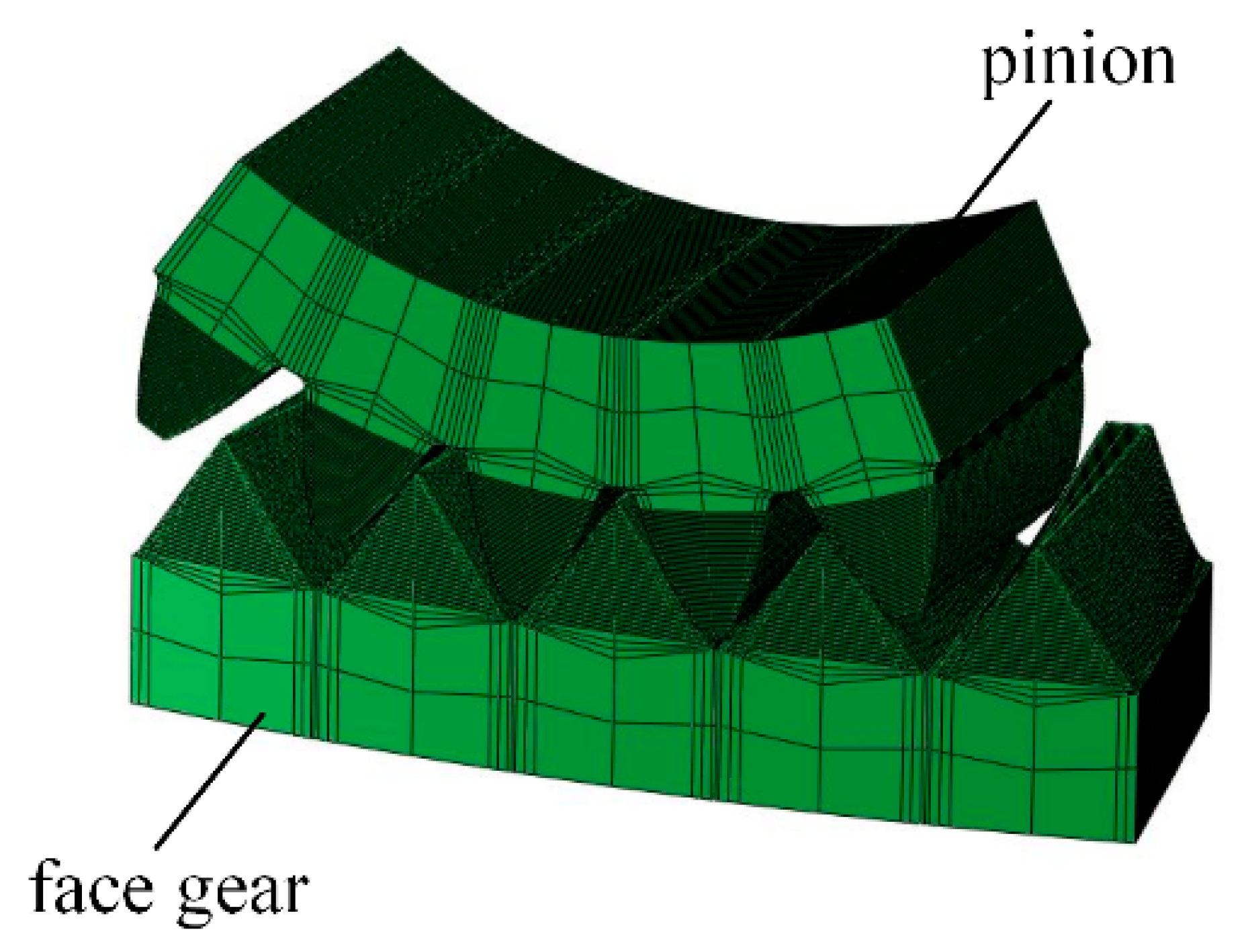
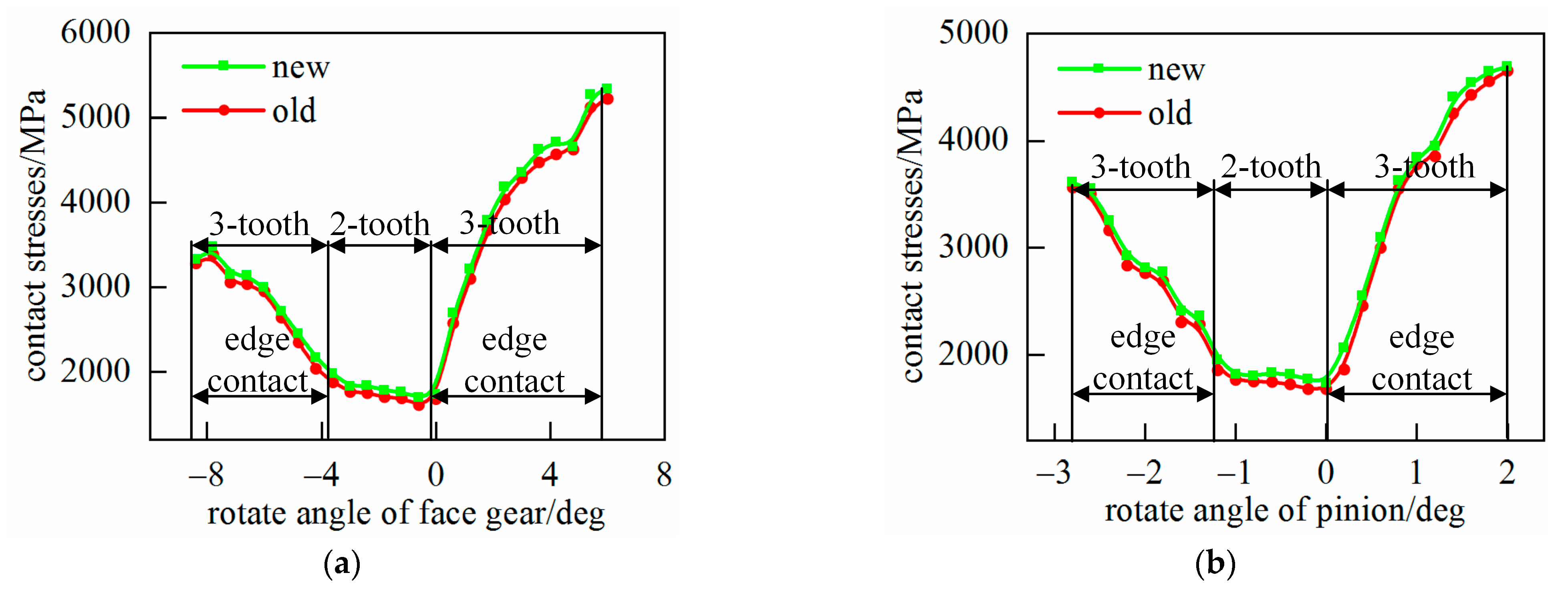
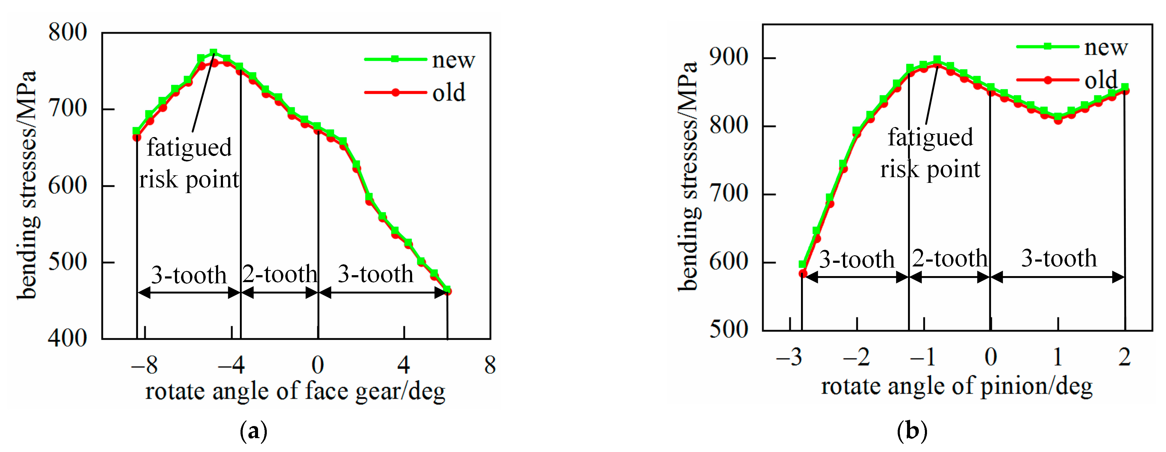
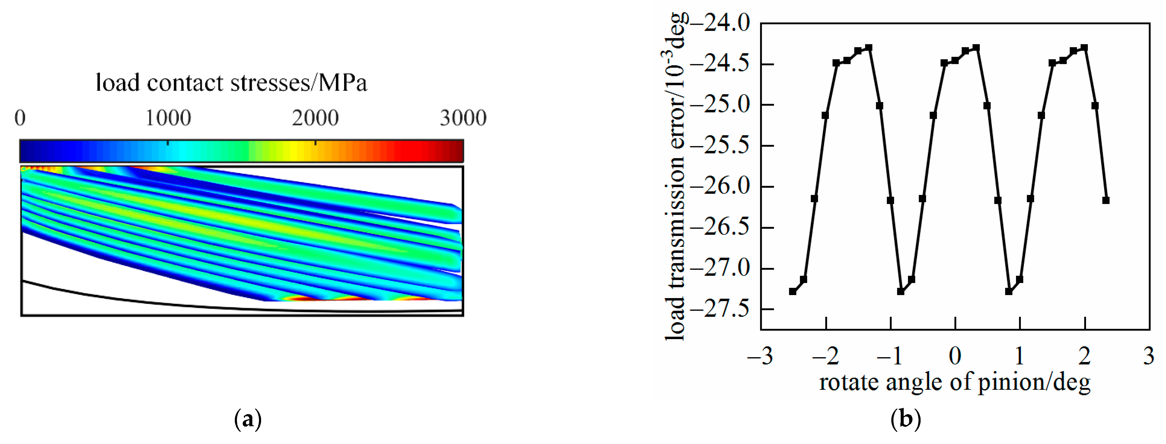
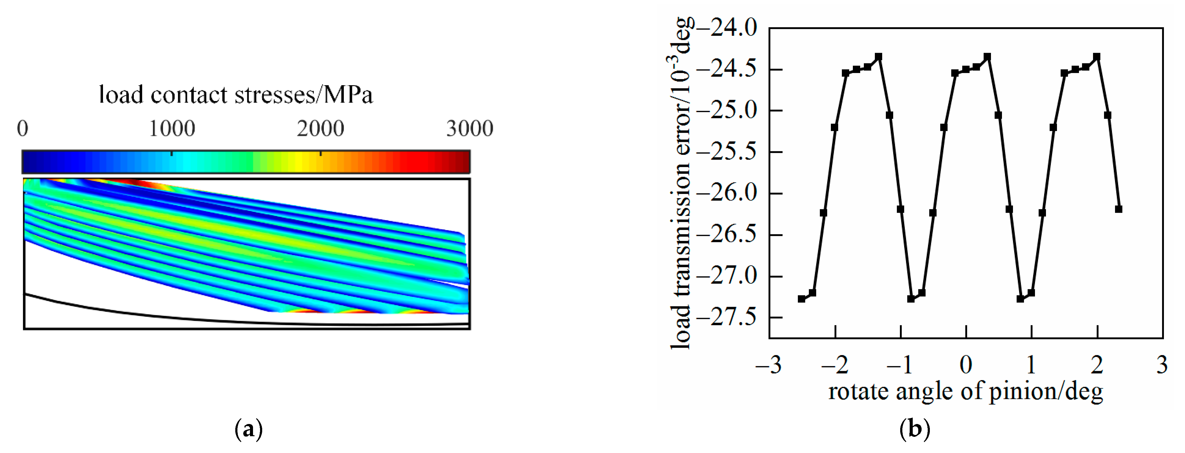
In general, in order to design high-performance gear transmissions or evaluate the meshing performance of gear pairs, tooth contact analysis (TCA) is required, which is a method of determining the tooth contact position, tooth contact area, and geometric transmission error through numerical simulation. However, in practical applications, gear pairs need to withstand a certain load, and the load tooth contact analysis (LTCA) technology can better simulate the working performance under real working conditions. Through LTCA, the bearing contact imprint, tooth surface contact stress, tooth root bending stress, bearing transmission error, etc., of gears can be obtained, which is of great significance for shortening the cycle, reducing costs, and designing high-quality gears. Lu [31] presented a new process of the TCA algorithm, which can reduce the calculation amount and speed up the calculation. Wu [32] studied a new integration method for the generative design of face gears, which can improve the speed of CAD modeling and CAE finite element analysis.
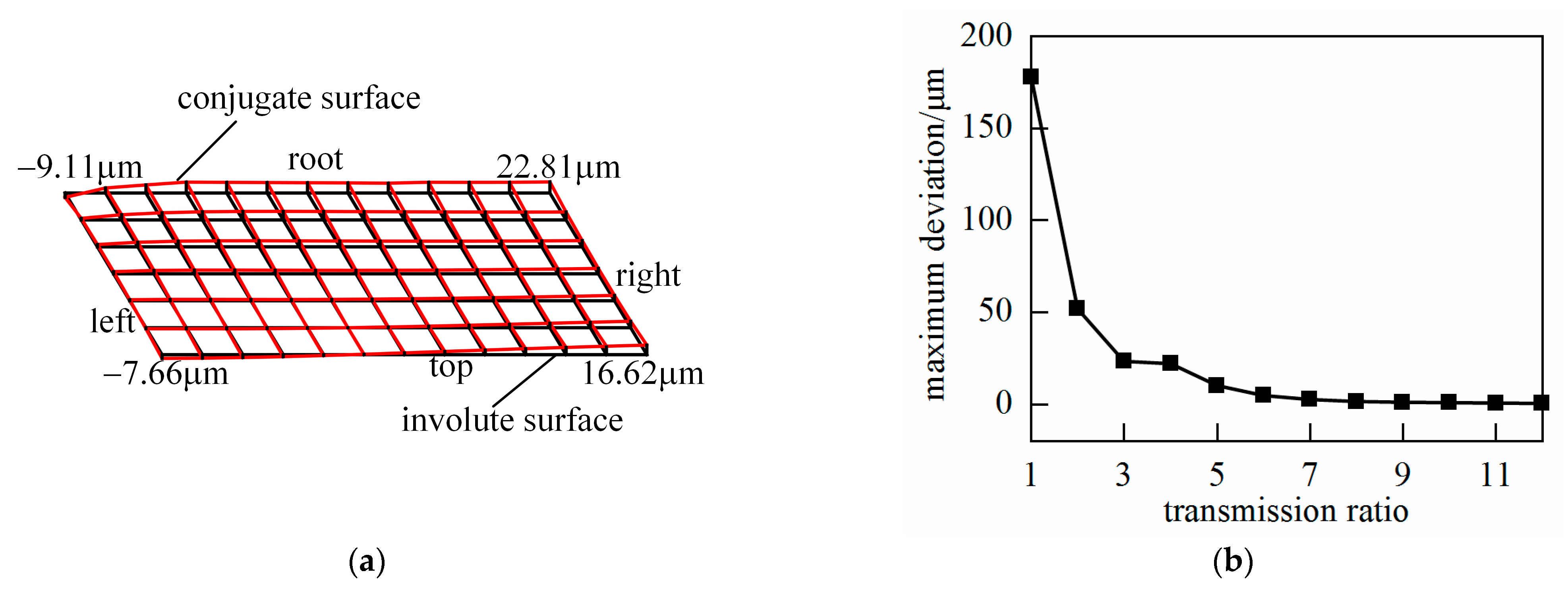
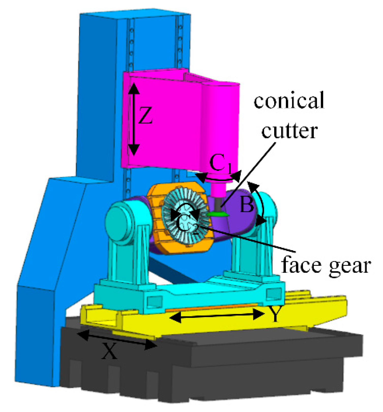
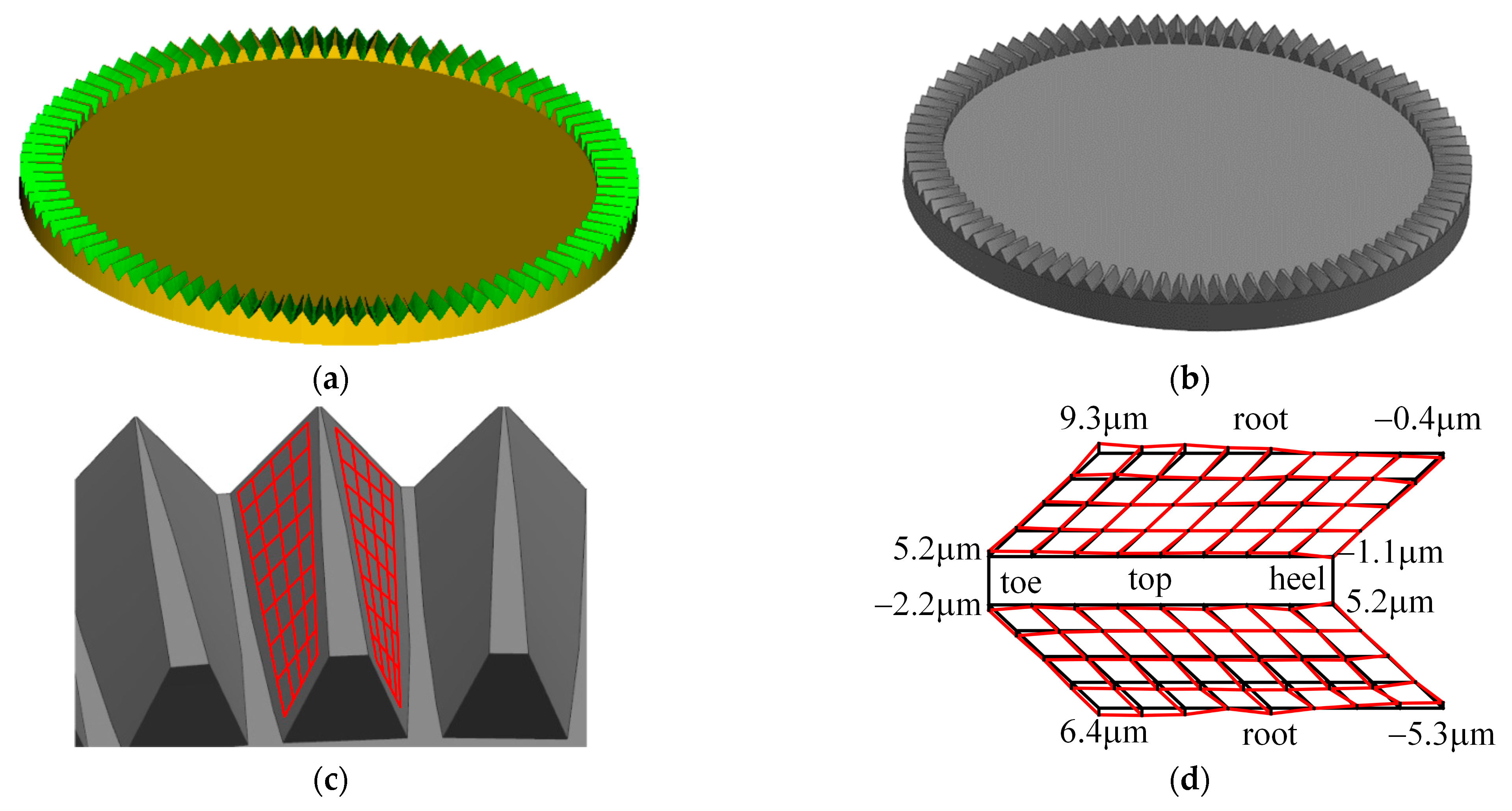
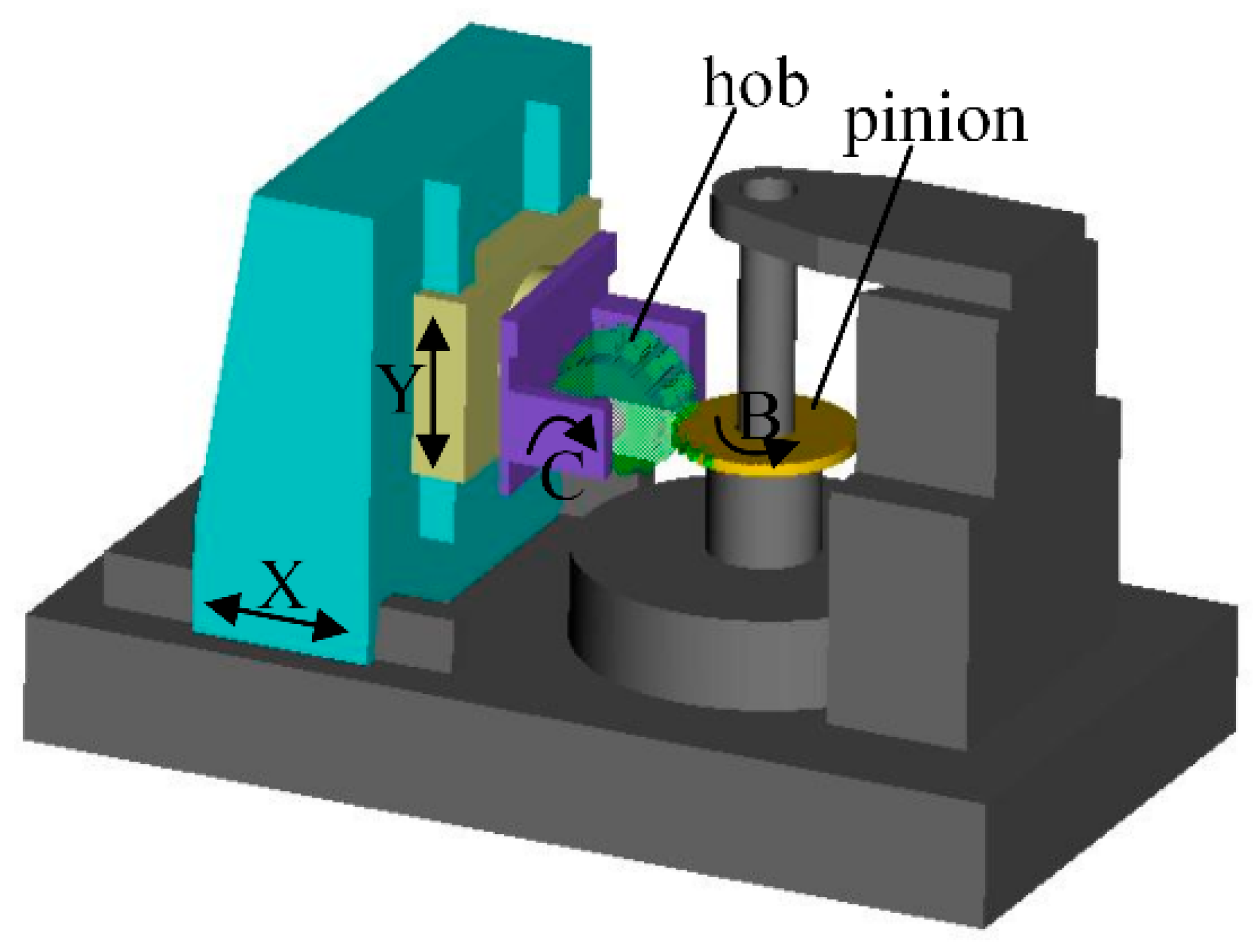
Based on the concept of the ruled surface of face gears, this paper proposes a method for machining ruled surfaces with conical cutters. So as to obtain the theoretical model of ruled surfaces, the mathematical model of the conical cutter will be defined, and the motion rules of the cutter will be derived according to the process of generating the ruled surface. Then, the influence of the basic parameters of face gears on the surface deviation between ruled surfaces and surfaces generated by a gear shaper (conventional face gears) will be studied and a new pinion to correct the significant deviations proposed when the transmission ratio is less than or equal to 4. The equations of the new pinion will be derived, and the machining method presented. Finally, the load tooth contact analysis (LTCA) will be performed to verify the feasibility of replacing conventional face gears with ruled surface face gears, and the machining simulations of the ruled surface and the new pinion will be performed with the VERICUT8.0 software to verify the correctness of machining methods.

2. Conventional Face Gear Pair

2.1. Tooth Surface of Involute Gears

Involute gears not only serve as gear cutters during the gear shaping process of face gears, but participate in meshing as pinions during the gear transmission process of face gears. Considering the impact of installation errors, the number of teeth of the gear shaping cutter will be 1 to 3 more than that of the pinion. The general involute tooth surface Σc can be expressed by the following equation:
R c = r c [ sin ( θ 0 + θ s ) θ s cos ( θ 0 + θ s ) ] r c [ cos ( θ 0 + θ s ) + θ s sin ( θ 0 + θ s ) ] u s 1
where
θ 0 = π 2 N c tan α + α
where rc is the radius of the base circle of the gear cutter, Nc is the number of teeth of an involute gear, α is the pressure angle, us is the tooth width, and θs is the spread angle of the involute gear, the unit normal vector is as follows:
n c = R c u s × R c θ s R c u s × R c θ s = cos ( θ 0 + θ s ) sin ( θ 0 + θ s ) 0 .

2.2. Tooth Surface of Face Gears

The tooth surface of a face gear is defined based on the gear shaping process of a involute gear, as shown in Figure 1. In this case, the angle between the shaft of the face gear and the involute gear is 90°, and the angle of the involute gear φc and the angle of the face gear φf satisfy the relationship shown in Equation (6), where Nf is the number of teeth of the face gear.
φ c φ f = N f N c
Hence, the position vector Rf and the normal vector nf of the face gear surface Σf are obtained through the coordinate transformation of the following equation. The coordinate systems Sc and Sd are established on the gear cutter, where Sc is fixed in space and Sd rotates with the cutter; Se and Sf are on the face gear coordinate systems, where Se is fixed and Sf rotates with the face gear; and rf and rp are the pitch radius of the face gear and the cylindrical gear.
R f ( u s , θ s , φ f ) = M f d ( φ f ) R c ( u s , θ s )
n f ( u s , θ s , φ f ) = M f d ( φ f ) n c ( u s , θ s )
M fd = M f e M e d M c d
M c d = cos φ c sin φ c 0 0 sin φ c cos φ c 0 0 0 0 1 0 0 0 0 1   M e c = 1 0 0 0 0 cos γ sin γ r f 0 sin γ cos γ r p 0 0 0 1   M f e = cos φ f sin φ f 0 0 sin φ f cos φ f 0 0 0 0 1 0 0 0 0 1
The cutter and face gear satisfy the following meshing equation, the theoretical face gear tooth surface can be successfully obtained.
f 2 u s , θ s , φ f = n c R f u s , θ s , φ f φ f = 0

3. Ruled Surface for Face Gears

3.1. Tooth Surface Equation of Ruled Surfaces

A ruled surface is a special surface composed of a family of straight lines, that is, a line passing through each point on the curve falls on that surface, as shown in Figure 2a, and the general expression can be represented by the following equation:
g ( u , v ) = a ( u ) + v b ( u )
where a(u) represents the leading line, b(u) is the unit vector on the straight line passing through a point a(u) on the leading line, and the distance from a point on the ruled surface to a point a(u) on the leading line is v.
In the meshing process of conventional face gear pairs, a special contact line Lr is shown in Figure 2b, in which Lr extends from the top of the toe to the root of the heel, and the line Lr is an involute extending in the longitudinal direction of the face gear tooth that is tangent to the surface Σc and Σf. If this special line Lr is considered as a leading line, a family of lines that are tangent to Lr at different cross sections or to the end face involute at different points that are arranged in the longitudinal direction of the face gear tooth and change with respect to the pressure angle are generatrices, so the tooth surface of the face gear can be seen as a ruled surface, as shown in Figure 3b, which greatly facilitates its manufacturing process. Compared with the implicit equation given in the reference [29,30], the explicit expression of the ruled surface is derived in this paper. The ruled surface of a orthogonal-straight tooth face gear can be obtained by the following process.
At any point on this line Lr, the linear velocities of the pinion and face gear are equal, which are represented as follows:
r q w c = L q w f sin γ = L q w f N f sin γ N c
where rq and Lq are the distance from point q on the line to axes zc and zf, respectively, and wc and wf are the angular velocities of the pinion and face gear, respectively. As shown in Figure 3a, any point on the involute, rq can be expressed as follows:
r q = r c cos ( θ s + θ 0 )
Hence, Lq can be expressed as shown in Equation (12).
L q = r c N f N c cos ( θ s + θ 0 ) s i n γ
By taking Equation (12) into consideration, the position vector R2 of the ruled surface can be represented by the following formulas:
A = O a O b = r c tan ( θ 0 + θ s ) r c θ s
L 0 = O 2 O c = r q tan γ + L q
R 2 = M 2 c M cb M ba R a = M 2 a R a
M 2 s = 1 0 0 0 0 cos γ sin γ L 0 sin γ 0 sin γ cos γ L 0 cos γ 0 0 0 1     M c b = 1 0 0 0 0 1 0 r q 0 0 1 0 0 0 0 1
M b a = cos ( θ 0 + θ s ) sin ( θ 0 + θ s ) 0 A cos ( θ 0 + θ s ) sin ( θ 0 + θ s ) cos ( θ 0 + θ s ) 0 A sin ( θ 0 + θ s ) 0 0 1 0 0 0 0 1     R a = 0 u a 0 1
where Ra represents the generatrix of the ruled surface, ua is the distance from any point on the generatrix to the contact line Lr, and Mij is a matrix of coordinate transformations from system Sj to Si. The normal vector n2 can be expressed as:
n 2 = R 2 u a × R 2 θ s R 2 u a × R 2 θ s .

3.2. Machining Method for Ruled Surfaces

The conventional cutting tools for machining face gears are based on the principle of gear shaping, which requires cutting tools to profile the theoretical tooth profile of the normal section of the gear shaping, resulting in low machining efficiency; although the ruled surface was proposed in the literature [29,30], it used the tooth milling machining method, which could not significantly reflect the machining advantages of the ruled surface. However, the ruled surface is defined by the linear family, and the use of cylindrical milling cutters, planar cutters, and cone disk milling cutters for line contact machining can greatly improve machining efficiency, and these cutting tools own simple structures and facilitate convenient manufacturing progress with extremely low manufacturing costs. This section deduces the equation of the conical cutter and derives the motion rules of the tool based on the principle of motion equivalence, ultimately obtaining the ruled surface.

3.2.1. The Conical Cutter

The geometric structure of the conical cutter is shown in Figure 4, and the occurrence line lt on its axial section is the cutting edge of the tool. Its length needs to meet the tooth height of the face gear and should not be less than 2.25 m, and considering the service life of the cutter, large diameter cutters are used to reduce their wear rate; wt = ltsinβt determines the thickness of the conical tool, which should not be greater than the tooth gap width of the outer root and inner top of the face gear, so the rang of the tool inclination angle value βt can be determined; the distance from the moving point on the cutting edge to the bottom of the tool is ut; therefore, the position vector ra of the cutting edge on the cross section of the tool shaft can be obtained:
r a = ( l t u t ) s i n β t h t ( l t u t ) cos β t 0 1
where ht is the upper radius of the conical cutter, after the axis cross section vector ra is transformed through rotational coordinates, the position vector Rt and normal vector nt of the cutter are obtained:
R t ( φ t , u t ) = M ta ( φ t ) r a ( u t )
M ta = 1 0 0 0 0 cos φ t sin φ t 0 0 sin φ t cos φ t 0 0 0 0 1
n t ( φ t , u t ) = R t φ t × R t u t R t φ t × R t u t .

3.2.2. The Motion Rules of the Cutter

Due to the fact that the ruled surface is a family of modified straight lines with a variable pressure angle, the cutting edge of a conical cutter can meet the variation of the pressure angle as long as it rotates around the z-axis, and the modified requirements can be met through the movement of the x, y, and z-axes, and the coordinate systems of ruled surface generation is shown in Figure 5. Therefore, in the process of machining ruled surfaces with the conical cutter, only four movements of the tool are required, and the tooth blank remains stationary. The position vector equation for machining ruled surfaces with the conical cutter can be expressed by the following equation, where X, Y, and Z are the movements along their axis of motion, C is the rotation of the cutter around the z-axis, and γ2 is the angle of intersection of the axes.
R 2 c ( u t , φ t , X , Y , Z , C ) = M 2 t c ( X , Y , Z , C ) R t ( u t , φ t )
M 2 t c ( X , Y , Z , C ) = M 2 u ( X , Y , Z ) M u t ( C )
M u t = cos C sin C 0 0 sin C cos C 0 0 0 0 1 0 0 0 0 1     M 2 u = 1 0 0 X 0 cos γ 2 sin γ 2 Z 0 sin γ 2 cos γ 2 Y 0 0 0 1
For the ruled surface, whether the forming process is theoretical generation or CNC machining, the spatial position and direction of the two methods are the same for the cutter. The transformation matrix M 2 t c of CNC machining is shown in Equation (20), and according to the previous section, the transformation matrix M2p of the theoretical ruled surface is shown in Equation (22).
M 2 p = M 2 c M cb M ba M at R t
M t a = cos β t sin β t 0 h t sin β t sin β t cos β t 0 h t cos β t + l t l a 0 0 1 0 0 0 0 1
where
l a = r c cos α + 1.25 m + A sin ( θ 0 + θ s ) r q cos ( θ 0 + θ s )
where m is the gear module. According to the principle of motion equivalence, the CNC motion rules of the cutter are derived in Equations (24) and (25).
M 2 p ( u t , θ s ) = M 2 t c ( X , Y , Z , C )
X = h t sin ( θ 0 + θ s β t ) + ( l t l a ) s i n ( θ 0 + θ s β t ) A cos ( θ 0 + θ s β t ) Y = h t c o s ( θ 0 + θ s β t ) + ( l t l a ) cos ( θ 0 + θ s β t ) + A sin ( θ 0 + θ s β t ) r q Z = r c N f N c cos ( θ 0 + θ s ) C = θ 0 + θ s β t
From the above equations, it can be seen that the motion rules of the cutting tools are functions of θs, in order to obtain the CNC machining tooth surface, the tooth height and width should be limited, and it is necessary to combine the meshing equation of the following equation:
h l R 2 c ( 3 ) = 0 w l R 2 c ( 1 ) ^ 2 + R 2 c ( 2 ) ^ 2 = 0 f 3 u t , φ t , θ s = n t u t , φ t v t 2 ( θ s ) = 0
where hl and wl are the tooth height and width of face gear, respectively, vt2 is the speed of the cutter relative to the tooth blank, the motion tracks of the tool are calculated, and this coordinate system is used to write CNC programs in VERICUT8.0.

3.2.3. Numerical Examples of Machining Method

In order to verify the feasibility of machining ruled surface gears with conical cutter, two sets of ruled surface gears with different parameters were set up for verification, as shown in Table 1. The deviation between the tooth surface machined by the conical cutter and the theoretical developed tooth surface can be represented by the ease-off topology, which is a tooth surface deviation topology constructed by all grid node deviations, as shown in Figure 6.
From the graph, it can be seen that the maximum deviation is 0.07 μm, with a transmission ratio of 3, and the maximum deviation is −0.09 μm when the transmission ratio is 6. Therefore, conical cutters can be used to machine the ruled surface with no deviation, theoretically. Not only does it simplify the cutting tool without a new machine tool structure, but its line contact machining method also improves the machining efficiency of the face gear, which is of great significance for the rough machining of the face gear.

3.3. Analysis of Tooth Surface Deviations

The conventional tooth surface is regarded as a theoretical reference for comparison and analysis with the ruled surface processed by a conical cutter. The definition for the deviation is shown in Figure 7a. Any point Rf on the conventional tooth surface intersects with the ruled surface along its normal vector direction nf at a point R2, and the distance between the two points can be expressed as follows:
Δ = ( R 2 - R f ) n f .
Figure 7b shows the morphology of the tooth surface deviation, and the parameters are displayed in case 1 of Table 1. In the figure, the black mesh represents the standard surface and the red mesh represents the ruled surface. It can be seen that the deviation of the tooth surface at the contact line position is almost zero, the deviation increases as the tooth surface expands from the contact line to two sides, the maximum deviation δ1 is mainly at the root of the inner diameter tooth, followed deviation δ2 by the top of the outer diameter tooth, and the other two parts are almost zero.
In order to study the influence of transmission ratio on tooth surface deviation, the number of teeth of cylindrical gears is a constant value, and the number of teeth of face gears varies with the transmission ratio from 1 to 12. Deviation calculations are conducted on 12 sets of calculation examples. The variation of deviation between the inner and outer diameters of the tooth surface at the top and root of the tooth is shown in Figure 8a, when the transmission ratio is small, the inner diameter tooth root and outer diameter tooth top are still the main deviation positions. However, as the transmission ratio increases, their deviation gradually tends to zero. While the deviation at the inner diameter tooth top and outer diameter tooth root is almost always zero, independent of the transmission ratio. In order to study the influence of modules on tooth surface deviation, the number of teeth of the pinion and the face gear remains unchanged, and the tooth surface deviation is calculated with the module from 1 to 12, the results are shown in the Figure 8b, the ratio of tooth surface deviation to modules is a certain value, that is, under fixed transmission ratio conditions, and the tooth surface deviation is independent of modules.
This section presents the equations of ruled surfaces and conical cutters, and proposes a machining method of ruled surfaces with conical cutters, and the tooth surface deviation between ruled surfaces and conventional surfaces is analyzed. From the results, it can be seen that when the transmission ratio is greater than or equal to 5, the tooth surface deviation is almost 0, and the ruled surface can directly replace the conventional face gear without the tooth surface correction; however, when the transmission ratio is less than 5, the deviation is too large, which is not conducive to meshing with cylindrical gears, and at this point, surface deviation correction needs to be considered. If the tooth surface of face gears is modified, its modification is time-consuming, which can lead the cutter to wear easily and increase the cost of tool repair due to its high number of teeth. Simultaneously, in order to achieve modification motion, it is generally necessary to add new degrees of freedom and may also require the design of new machine tool structures, which increases manufacturing costs. In order to solve the above problems, the pinion is usually chosen to modify, and the next section proposes the conjugate pinion of the ruled surface and its machining method.

4. Conjugate Pinion with Ruled Surface Face Gear

4.1. Generation of Conjugate Pinions

From the definition of the ruled surface, it can be seen that the tooth surface of the ruled surface is no longer tangent to the tooth surface of the cylindrical gear, except for the contact line, especially at the root and top of the tooth, as shown in Figure 3. If the ruled surface is directly meshed with the cylindrical gear, it will inevitably generate a strong vibration and impact due to not meeting the conjugate relationship, accelerating the wear of the gear. Therefore, in order to avoid the occurrence of the above situations, the ruled surface is regarded as a tool for generating pinions, and is developed into a completely conjugate pinion tooth surface, which can be considered as a modified involute pinion. The coordinate systems of generation for pinions are shown in Figure 9.
The coordinate systems Sg and S2 in Figure 9 are the motion coordinate systems and fixed coordinate systems of the ruled surface gear, respectively; the coordinate systems Sn and Sj are the motion coordinate system and fixed coordinate system of the pinion, respectively; γj is the angle between the shaft of the ruled surface gear and the pinion; r2 and rj is the pitch diameter of the ruled surface and the pinion; and φ2 and φj is the angle of the ruled surface and the pinion, meeting the gear ratio.
By combining the coordinate transformation equation from S2 to Sj and the meshing equation between the two gears, the position vector Rj and normal vector nj of the conjugate tooth surface of the pinion can be determined:
R j ( φ r , θ , u ) = M jr ( φ r ) R 2 ( θ , u ) n j ( φ r , θ , u ) = M jr ( φ r ) n 2 ( θ , u ) f 3 ( φ r , θ , u ) = n j ( φ r , θ , u ) R j ( φ r , θ , u ) φ r
where Mjr is the coordinate transformation matrix from the ruled surface to the conjugate pinion, and its specific expression is similar to Mfd and will not be repeated.

4.2. Difference in Tooth Surface between Conjugate Pinions and Cylindrical Gears

Due to the fact that the conjugate tooth surface is no longer a simple regular surface, but a complex surface that constantly changes with tooth width, there are differences between the conjugate tooth surface and the tooth surface of cylindrical gears, as shown in Figure 10a, the parameters are shown in case 1 of Table 1, and the maximum deviation is at the root of left side of the tooth surface. According to the previous section, it is known that the transmission ratio is the largest factor to influence the deviation; therefore, the maximum deviation is calculated when the transmission ratio i = 1–12, as shown in Figure 10b.

4.3. The proposal of Machining METHOD for Conjugate Pinions

According to the difference between conjugate pinions and cylindrical gears under small transmission ratio conditions, the conjugate tooth surface can be regarded as a modified tooth surface based on the tooth surface of cylindrical (involute) gears. In order to produce a conjugate pinion, a correction motion can be added to the basic motion of the cylindrical gear. Without designing new cutters and machine tools to save economic costs, if the forming method is used to process the conjugate tooth surface, the irregular surface cannot be corrected due to the linear contact between the cutter and the tooth surface; the generative method is used for point contact machining of conjugate tooth surfaces. Compared to gear shaping machining, a hobbing method can achieve continuous cutting, higher cutting speed, and better machining efficiency. Therefore, gear hobbing can be used for machining of conjugate tooth surfaces.

5. The Processing Method of Conjugate Pinions

5.1. Mathematical Model of Hob

In the hobbing method, Archimedes worm hobs are the most widely used due to their relatively simple manufacturing and measurement, which can be seen as infinitely long racks meshing with gears, and the machining principle is shown in Figure 11a. The axial section of the worm is shown in Figure 11b, and the production lines I and II spiral around the worm axis, forming the helical surfaces on both sides of the worm, respectively. Due to the symmetry of the production line about the x-axis, the expressions for the spiral surfaces of the two are similar, only the equation expression for the right spiral surface is given:
R h = u h cos α h cos θ h u h cos α h sin θ h u h sin α h ( r tan α h + s 2 ) + p h θ h 0
where
p h = m 2 s = m π 2 2 x h m
where xh is the tangential displacement coefficient, uh is the position of any point on the production line, θh is the rotation angle of the spiral motion, αh is the tooth shape angle, r is the indexing circle radius of the worm, and its normal vector nh can be expressed as:
n h = cos α h ( p h sin θ h u h cos α h sin θ h ) cos α h ( p h cos θ h + u h sin α h sin θ h ) u h cos 2 α h 0 .

5.2. Coordinate Systems Used for Involute Gear Generation by Hobbing

The generation from Archimedes worm hobs into involute gears is a dual parameter process. In addition to the cutting motion of the hob and the meshing motion of the workpiece, there is also the feed motion of the hob in the transverse direction. The coordinate system for hobbing machining motion is shown in Figure 12.
The coordinate systems Sh and Sc in Figure 11 are fixedly connected to the hob and workpiece, respectively; Sp and Sq are the motion coordinate systems of the hob and the workpiece; Ss is the coordinate system after the hob is tilted during actual installation; Sk is an auxiliary coordinate system; Ls is the axial feed distance of the hob, φc and φh are the rotation angle of the workpiece and the hob, β is the installation angle of the hob holder; and L is the sum of the pitch radius of the hob and the workpiece. According to Figure 11, the coordinate transformation matrix Mch from Sh to Sc can be established, and the position vector Rc and normal vector nc of the cylindrical gear are as follows:
R c ( φ h , L s , θ h , u h ) = M ch ( φ h , L s ) R h ( θ h , u h )
n c ( φ h , L s , θ h , u h ) = M ch ( φ h , L s ) n h ( θ h , u h )
M c h = M c q M q s M s p M p h
M p h = cos φ h sin φ h 0 0 sin φ h cos φ h 0 0 0 0 1 0 0 0 0 1     M s p = 1 0 0 0 0 cos β sin β 0 0 sin β cos β 0 0 0 0 1
M q s = 1 0 0 L 0 cos γ h sin γ h 0 0 sin γ h cos γ h L s 0 0 0 1     M c q = cos φ c sin φ c 0 0 sin φ c cos φ c 0 0 0 0 1 0 0 0 0 1
and combined with the meshing equation, the theoretical model of cylindrical gears is obtained.
f 4 ( φ h , L s , θ h , u h ) = n c R c φ h
f 5 ( φ h , L s , θ h , u h ) = n c R c L s

5.3. Machining Method for Conjugate Tooth Surface

In order to machine the ideal conjugate tooth surface, in addition to the basic movements mentioned above, the radial movement ΔL of the hob and the additional rotation Δφ of the workpiece should be considered simultaneously, as shown in Figure 13. So as to obtain additional motion laws, Δφ and ΔL are represented by a Taylor polynomial at φh = 0, and the equations are as follows:
Δ φ = a 0 φ h 0 + a 1 φ h 1 + a 2 φ h 2 + a 3 φ h 3 + a 4 φ h 4 + a 5 φ h 5 + a 6 φ h 6 Δ L = b 0 φ h 0 + b 1 φ h 1 + b 2 φ h 2 + b 3 φ h 3 + b 4 φ h 4 + b 5 φ h 5 + b 6 φ h 6
where an and bn are the nth (n = 0, 1, 2,…, and 6) order coefficients for the additional rotation angle Δφ and the additional movement ΔL, respectively. Therefore, the position vector and normal vector of the conjugate pinion are represented by the following equation:
R 1 c ( φ h , L s , θ h , u h ) = M 1 h ( a n , b n , φ h , L s ) R h ( θ h , u h ) n 1 c ( φ h , L s , θ h , u h ) = M 1 h ( a n , b n , φ h , L s ) n h ( θ h , u h )
where M1h is the coordinate transformation matrix after additional motions.
In order to solve the additional motion coefficients, a sensitivity matrix can be listed. The theoretical conjugate tooth surface is dispersed into a grid, and its value for each point is calculated, which can be written as a column vector δ 1 c = δi (i = 1, 2,…, q); the coefficients an and bn are merged into a column vector c = cj (j = 0, 1, 2,…, p, p = 7 × 2 = 14), and Δc is set as an increment that causes the change in the tooth surface position vector. Therefore, the sensitivity matrix equation can be expressed as:
δ 1 c ( q × 1 ) = J ( q × p ) Δ c ( p × 1 )
where J is the sensitivity matrix, which is composed by partial derivatives, and it represents the degree of response of the target modification value when the increment changes, which can be expressed as follows:
J = n c [ R 1 c ( c j + Δ c j ) R c ] Δ c j
where Δcj is the unit increment of coefficient cj. Due to the deviation values being too small, Equation (39) is usually ill conditioned, and the singular value decomposition method is used to iteratively solve the equation, where the singular value decomposition formula of the sensitivity matrix is:
Γ Ω Λ = s v d ( J )
when the following conditions are met, the iteration stops and the parameters are obtained.
H = δ 1 c n c [ R 1 c ( c j + Δ c j ) R c ] H T H 10 3
Considering that during the actual machining process, due to the additional rotation Δφ of the workpiece, the rotation between the hob and the workpiece no longer meets the transmission ratio, resulting in over cutting during the processing of standard worm hobs, as shown in Figure 13. Therefore, the hob should be tangentially modified, as shown in Figure 11b; during the machining process, the cutting edge on one side is used for cutting, and after machining the single tooth surface, the cutting edge on the other side is located at the position before tangential modification, and the directions of the hob and the workpiece are changed simultaneously to produce a symmetrical tooth surface.

5.4. Numerical Examples of Machining Method

In order to ensure that the hob does not produce over cutting under the influence of additional motion during the machining process, the positional relationship between the cutting edge of the hob and the tooth profile is given, and the parameters of two sets of examples are shown in Table 2.
Figure 14 is a diagram showing the positions of the cutting edge of a hob relative to the conjugate tooth profile and the positions of the conjugate tooth profile relative to the involute tooth profile when the tooth profile with the largest deviation is processed, respectively, at a transmission ratio of 1 and 3. From the figures, it can be seen that the cutting edge of the hob is close to tangent at every point of the tooth profile, without any over cutting phenomenon, indicating the feasibility of machining motion.
Figure 15 shows the deviation between the tooth surface of cylindrical gears and the conjugate tooth surface when the transmission ratio i is 1, as well as the machining effect of the CNC machining of the conjugate tooth surface. Figure 15a shows the tooth surface deviation, with a maximum deviation of 158.51 μm. By iterating multiple times to solve the coefficient of additional motion in gear hobbing, the final polynomial coefficient results are shown in Table 3. The maximum error between the CNC machining tooth surface and conjugate surface is only 7.25 μm, which is shown in Figure 15b.
Figure 16 shows the deviation between the tooth surface of cylindrical gears and the conjugate tooth surface when the transmission ratio i is 3, as well as the machining effect of CNC machining of the conjugate tooth surface. The polynomial coefficients of the motion axis obtained through multiple iterations of the singular value decomposition method are shown in Table 4, and the maximum value of surface deviation is 14.02 μm. The maximum machining surface compared to conjugate tooth surface is only 0.65 μm.
From two sets of examples, it can be seen that even if the deviation value of the conjugate tooth surface changes within a wide range, the CNC machining tooth surface can approach the conjugate tooth surface well, and the theoretical error can be controlled within 8 μm, it indicates the correctness of the method for hobbing conjugate tooth surfaces, and the use of singular value decomposition to solve the sensitivity matrix equation to obtain the increment of polynomial coefficients is stable.

6. The Load Performance of Ruled Surface Face Gear Pair

By using the above method, a pair of ruled surface face gear pairs with high machining efficiency can be obtained. In order to explore whether they can replace traditional face gear pairs, it is necessary to study their load contact characteristics [33]. A set of conventional face gear pairs is designed to compare with ruled surface face gear pairs, and the differences between the two can be received. The basic parameters of the two sets of gear pairs are the same, as shown in case 2 of Table 2.

6.1. Establishment of Finite Element Model

Due to the large computational scale, low efficiency, and difficulty in convergence of the overall finite element model of the face gear pair, a local five-tooth meshing finite element model was established to facilitate obtaining the meshing characteristics of the ruled surface face gear pair, as shown in Figure 17. The gear components of this model are all based on tooth surface equations, and are assembled after meshing. The parameter settings for the finite element model are as follows.
(1)
The material properties used are: density 7800 kg/m3, elastic modulus 206.8GPa, and Poisson’s ratio 0.29.
(2)
The model uses hexahedral elements and the mesh density is 81 × 51 (tooth width × tooth height).
(3)
The tooth contact is defined as face-to-face frictionless contact, with the right tooth surface of the face gear as the main surface and the corresponding tooth surface of the pinion as the secondary surface.
(4)
This model adopts static analysis method to limit all degrees of freedom except for the rotation of the pinion around the shaft, and applies a torque of 1600 N·m.
The above operations are parameterized through programs developed in MATLAB2014b. After generating the corresponding INP files, they are imported into the finite element software ABAQUS6.14 for calculation. The calculation results (odb files) are imported into the finite element software for post-processing to extract the relevant characteristic parameters of gear tooth bearing.

6.2. Finite Element Analysis of Result

At present, the edge contact caused by the line contact of two completely conjugate gear pairs will not be considered temporarily. Only the difference in load performance between the new face gear pair and the old face gear pair will be compared.
Figure 18 shows the almost identical tooth contact stress of two sets of gear pairs under the same load; the maximum difference between the new and old face gear is 0.67% of the old, and the maximum difference of two kinds of pinions is 1.47% of the old. Figure 19 shows the same tooth surface bending stress of two gear pairs; the maximum difference of two face gears is 1.29% of the old, and the maximum difference of two pinions is 1.06% of the old. Figure 20 and Figure 21, respectively, show the load imprints and load transmission errors of old face gear pairs and new face gear pairs, and it is found that the two are almost identical, the maximum difference of load transmission error being less than 0.0003 deg.
Therefore, in situations where the transmission ratio is less than 5, the application of traditional face gear pairs can be replaced by ruled surface face gear pairs, leveraging the machining advantages of ruled surface face gears. As for the issue of edge contact, literature [6] restricts the contact imprint to a local area through the difference in the number of teeth between the pinion and the gear shaper, which can solve the problem of edge contact; Reference [34] improves the meshing characteristics of gears by actively modifying method. Thus, by actively designing the tooth surface of the pinion, it can obtain tooth surfaces with better meshing performance while maintaining the superiority of machining method of ruled surface. The above methods can be used for the tooth surface design of ruled surface gear pairs, but this research is not the focus of this paper, so it will not be further discussed.

7. Machining Simulation Verification Based on VERICUT

7.1. Machining Simulation of Ruled Surface Face Gears

In order to verify the correctness of machining ruled surface face gears with conical cutter, a five-axis machining center was established in VERICUT [35], as shown in Figure 22. The design parameters of the conical cutter are shown in Table 5, and that of face gear are shown in case 1 of Table 1. A code file was developed according to the generation principle, and the machining simulation was performed.
The machining center model consists of three axes with linear motion and three axes with rotational motion (the rotation of the conical cutter, the rotations of face gear blank in the z-axis and y-axis directions). The machined ruled surface is shown in Figure 23a, the theoretical model is shown in Figure 23b. The single tooth machining result is imported into MATLAB in STL format, the tooth surface is discretized into a 5 × 9 grid to compare with the theoretical surface in Figure 23c. The error of simulation is obtained as shown in Figure 23d, it is observed that the maximum residual error is 9.3 μm and the maximum over cutting error is 5.3 μm, confirming the correctness of machining ruled surfaces with conical cutters.

7.2. Machining Simulation of Conjugate Pinions

In order to verify the correctness of the machining method of conjugate pinions proposed in Section 4, a machine tool model was established in VERICUT as shown in Figure 24. The design parameters of the hob are shown in the Table 6, and the design parameters of the pinion are shown in case 2 of Table 2. According to the machining method of conjugate pinions, a CNC program was developed, and the machining simulation was performed.
In this model of the machine tool, the moving axis X is responsible for the radial motion of the hob; the moving axis Y is responsible for the feed motion of the hob; the rotating axis B is responsible for the comprehensive rotation of the pinion (the sum of general separation motion and additional rotation); and the rotation axis C is responsible for the rotation of the hob.
The machined pinion is shown in Figure 25a. Using the same data extraction method as the face gear in Section 6.1, the simulation error is shown in Figure 25b. By comparing the error, it can be seen that the maximum error is less than 6 μm, confirming the feasibility of machining conjugate pinions with hobs.

8. Conclusions

Based on the performed research work, the following conclusions can be drawn:
(1)
The computerized generation of ruled surface face gears generated by conical cutter was presented.
(2)
The transmission ratio is the main factor affecting the deviation between ruled surface face gear and traditional face gears. When the transmission ratio is less than or equal to 4, due to the large deviation of the tooth surface, it is proposed to correct the cylindrical gear.
(3)
By adjusting the radial motion of the hob and the rotation of the pinion, the conjugate pinion can be machined through gear hobbing.
(4)
By load tooth contact analysis and machining simulation, the feasibility of replacing traditional face gear pairs with ruled surface face gears was verified, demonstrating the superiority of ruled surface machining.

Author Contributions

Conceptualization, X.P.; methodology, X.P. and Y.W.; theoretical analysis, X.P. and Y.W.; validation, X.P. and Y.W.; writing-original draft preparation, Y.W.; writing-review and editing, X.P.; funding acquisition, X.P.; All authors have read and agreed to the published version of the manuscript.

Funding

The research was funded by the Shaanxi Provincial Natural Science Foundation of China (2020JM-521) and Special Research Project on Spent Fuel Reprocessing (KY22002).

Institutional Review Board Statement

Not applicable.

Informed Consent Statement

Not applicable.

Data Availability Statement

The datasets presented in this article are not readily available because the data are part of an ongoing study.

Conflicts of Interest

Author Xianlong Peng was employed by the company China Nuclear Power Engineering Co., Ltd. The remaining authors declare that the research was conducted in the absence of any commercial or financial relationships that could be construed as a potential conflict of interest.

Nomenclature

anPolynomial coefficient of additional roatation
bnPolynomial coefficient of radial movement
a,bUnit vectors in different directions of ruled surface
cColumn vector merged with polynomial coefficients
δ 1 c Column vector composed of target values
JSensitivity matrix
rcRadius of the base circle of the gear cutter
L1, L2Inner radius and outer radius of the face gear
SiCoordinate system
MijTransformation matrix from coordinate system Sj to coordinate system Si
RiPosition vector of the surface of gear i
niUnit normal vector of the surface of gear i
mModule
gRuled surface
riPitch radius of gear i
NiNumber of teeth of gear i
α, αhPressure angle of gear and hob
γCrossed-axis angle between the face gear and the pinion
γ2Crossed-axis angle between the ruled surface face gear and the conical cutter
γjCrossed-axis angle between the ruled surface face gear and the conjugate pinion
φiRotational angle of gear i
rqDistance from point q to axes zc
LqDistance from point q to axes zf
utDistance from the moving point on the cutting edge to the bottom of the tool
ltCutting edge of conical cutter
htUpper radius of conical cutter
βtInclination angle of conical cutter
βInstallation angle of the hob holder
CRotational angle of conical cutter
X,Y,ZCoordinates of translational axes x,y,z
xhModification coefficient of hob
phSpiral parameters of hob
sTooth thickness of hob
θhRotational angle of spiral motion
I, IIRight and left production line of hob
LSum of radius of hob and workpiece
LsFeed distance of hob
ΔφAdditional rotation angle of workpiece
ΔLRadial movement of hob
ΣiTooth surface of gear i
θsSpread angle of the involute gear
usTooth width of the involute gear
uaDistance from any point on the generatrix to the contact line Lr
u,vParameters of ruled surface
LrLeading line of ruled surface
hlTooth height of face gear
wlTooth width of face gear

References

  1. Litivin, F.L.; Wang, J.C.; Bossler, R.B.; Chen, Y.J.; Heath, G. Application of face-gear drives in helicopter transmissions. J. Mech. Des. 1994, 116, 672–676. [Google Scholar] [CrossRef]
  2. Heath, G.F.; Filler, R.R.; Tan, J. Development of Face Gear Technology for Industrial and Aerospace Power Transmission; NASA/CR-2002-211320; ARL-CR-0485; Army Research Laboratory: Adelphi, MD, USA, 2002. [Google Scholar]
  3. Wang, Z.; Shi, Z.Y. Characteristics of face gear drive and its research developments. Tool Eng. 2009, 43, 10–14. [Google Scholar]
  4. Stadtfeld, H.J. Power skiving of cylindrical gears on different machine platforms. Gear Technol. 2014, 1, 52–62. [Google Scholar]
  5. Erkuo, G.; Rongjing, H.; Xiaodiao, H. Research on the cutting mechanism of cylindrical gear power skiving. Int. J. Adv. Manuf. Technol. 2015, 79, 541–550. [Google Scholar]
  6. Litivin, F.L.; Fuentes, A. Gear Geometry and Applied Theory, 2nd ed.; Cambridge University Press: New York, NY, USA, 2004. [Google Scholar]
  7. Litivin, F.L.; Fuentes, A.; Zanzi, C. Design, generation, and stress analysis of two versions of geometry of the face gear drives. Comput. Methods Appl. Mech. Eng. 2002, 37, 1179–1211. [Google Scholar]
  8. Litivin, F.L.; Egelia, A.; Tan, J. Handbook on Face Gear Drives with a Spur Involute Pinion; Technical Report No. ARL-CR-447; University of Illinois: Chicago, IL, USA, 2000. [Google Scholar]
  9. Miller, E.W. Hob for Generating Crown Gears. U.S. Patent 2,304,586, 8 December 1942. [Google Scholar]
  10. Basstein, G.; Sijtstra, A. New Developments in Design, Manufacturing and Applications of Cylkro (Face) Gears; AGMA Fall Technical Paper 93FTM7; AGMA: New York, NY, USA, 1993. [Google Scholar]
  11. Wang, Y.Z.; Hou, L.W.; Lan, Z. A precision generating hobbing method for face-gear based on worm hob. J. Mech. Eng. Sci. 2019, 231, 1057–1071. [Google Scholar] [CrossRef]
  12. Han, Z.Y.; Jiang, C.; Deng, X.Z. Machining and meshing analysis of face gears by power skiving. J. Adv. Mech. Des. Syst. 2022, 16, 21–00245. [Google Scholar] [CrossRef]
  13. Guo, H.; Ma, T.; Zhang, S.Y. Computerized generation and surface deviation correction of face gear drives generated by skiving. Mech. Mach. Theory 2022, 173, 104839. [Google Scholar] [CrossRef]
  14. Tsai, C.Y. Mathematical model for design and analysis of power skiving tool for involute gear cutting. Mech. Mach. Theory 2016, 101, 195–208. [Google Scholar] [CrossRef]
  15. Tsai, C.Y.; Lin, P.D. Gear Manufacturing Using Power-Skiving Method on Six-Axis CNC Turn-Mill Machining Center; Springer: London, UK, 2018; Volume 95, pp. 609–623. [Google Scholar]
  16. Litivin, F.L.; Fuentes, A.; Zanzi, C. Face-gear drive with spur involute pinion: Geometry, generation by a worm, stress analysis. Comput. Methods Appl. Mech. Eng. 2002, 191, 2783–2813. [Google Scholar] [CrossRef]
  17. Peng, X.L.; Fang, Z.D.; Sun, J.Z. Theory analysis for application grinding disk in face gear grinding. J. Aerosp. Power 2012, 27, 1159–1165. [Google Scholar]
  18. Zhou, R.C.; Zhao, N.; Li, W.; Li, R.; Guo, G.D.; Guo, H. A grinding method of face gear mating with a conical spur involute pinion. Mech. Mach. Theory 2019, 141, 226–244. [Google Scholar] [CrossRef]
  19. Tang, J.Y.; Yang, X.Y. Research of the plunge milling for face gear. J. Mech. Trans. 2015, 39, 5–8. [Google Scholar]
  20. Wang, Y.Z.; Tang, W.; Yin, Y.Y. Hobbing method of face gear based on spherical hob. J. Beijing Univ. Aeron. Astron. 2017, 43, 441–448. [Google Scholar]
  21. Buckingham, E. Analytical Mechanics of Gears; Dover Publications: New York, NY, USA, 1949. [Google Scholar]
  22. Stadtfeld, H.J. Coniface face gear cutting and grinding. Gear Solut. 2010, 10, 38–47. [Google Scholar]
  23. Kubo, A.; Ueda, A. Gear geometry as a function of the production method. Mech. Mach. Sci. 2018, 51, 27–44. [Google Scholar]
  24. Peng, X.L. A new geometry definition and generation method for a face gear meshed with a spur Pinion. J. Eng. Manuf. 2021, 236, 1037–1051. [Google Scholar] [CrossRef]
  25. Hu, Y.N.; Lin, C.; Li, S.; Yu, Y.Q.; He, C.J.; Cai, Z.Q. The Mathematical model of curve-face gear and time-varying meshing characteristics of compound transmission. Appl. Sci. 2021, 11, 8706. [Google Scholar] [CrossRef]
  26. Ivana, L.; Vít, Z. Application of ruled surfaces in freeform and gear metrology. Acta Polytech. 2021, 61, 99–109. [Google Scholar]
  27. Tan, J.; Mesa, A. Face gearing with conical involute pinion. U.S. Patent 5,941,124, 24 August 1999. [Google Scholar]
  28. Hsu, R.H.; Wu, Y.R.; Tran, V.T. Manufacturing helical gears with double-crowning and twist-free tooth flanks using a variable pressure angle shaving cutter. J. Eng. Manuf. 2019, 233, 77–86. [Google Scholar] [CrossRef]
  29. Zhou, Y.S.; Wang, S.H.; Wang, L.M.; Tang, J.Y.; Chen, Z.Z. CNC milling of face gears with a novel geometric analysis. Mech. Mach. Theory 2019, 139, 46–68. [Google Scholar] [CrossRef]
  30. Chu, X.M.; Zeng, H.; Wang, Y.Z.; Huang, Y.Z. Research on tooth surface design and side milling machining method of ruled line face gear. Int. J. Adv. Manuf. Technol. 2023, 124, 511–526. [Google Scholar] [CrossRef]
  31. Lu, X.X.; Zhou, Y.S.; He, D.; Zheng, F.Y.; Tang, K.; Tang, J.Y. A novel two-variable optimization algorithm of TCA for the design of face gear drives. Mech. Mach. Theory 2022, 175, 104960. [Google Scholar] [CrossRef]
  32. Wu, Y.H.; Zhou, Y.S.; Zhou, Z.Y.; Tang, J.Y.; Ouyang, H.W. An advanced CAD/CAE integration method for the generative design of face gears. Adv. Eng. Softw. 2018, 126, 90–99. [Google Scholar] [CrossRef]
  33. Yuan, B.; Liu, G.; Yue, Y.J. A novel tooth surface modification methodology for wide-faced double-helical gear pairs. Mech. Mach. Theory 2021, 160, 104299. [Google Scholar] [CrossRef]
  34. Chang, S.; Chung, T.; Lu, S. Tooth contact analysis of face-gear drives. Int. J. Mech. Sci. 2000, 42, 487–502. [Google Scholar] [CrossRef]
  35. Yang, S.Q. VERICUT NC Machining Simulation Technology; Tsinghua University Press: Beijing, China, 2010. [Google Scholar]
Figure 1. Generation of the face gear.
Applsci 14 00931 g001
Figure 2. Schematic diagrams of ruled surface and the special contact line of conventional face gear pair: (a) definition of ruled surface, and (b) a special contact line in surfaces Σc and Σf.
Applsci 14 00931 g002
Figure 3. Schematic diagram of the development of ruled surface: (a) generation coordinate system of ruled surface, and (b) generating result of ruled surface for face gear.
Applsci 14 00931 g003
Figure 4. The conical cutter.
Applsci 14 00931 g004
Figure 5. Coordinate systems for ruled surface generation.
Applsci 14 00931 g005
Figure 6. The deviation between the tooth surface machined by conical cutters and the theoretically developed tooth surface: (a) case 1, and (b) case 2.
Applsci 14 00931 g006
Figure 7. Tooth surface deviations of the ruled surface: (a) definition of the tooth surface deviation, and (b) tooth surface deviation morphology.
Applsci 14 00931 g007
Figure 8. The influence of basic parameters on the deviation of face gears: (a) transmission ratio and tooth surface deviation, and (b) module and tooth surface deviation.
Applsci 14 00931 g008
Figure 9. Generation of conjugated pinion.
Applsci 14 00931 g009
Figure 10. Deviation between conjugate surface and involute surface: (a) tooth surface deviation morphology; and (b) transmission ratio and tooth surface deviation.
Applsci 14 00931 g010
Figure 11. Theory of gear hobbing and modified hob: (a) hob equals an infinite rack, and (b) geometric shape of the cross section of the worm shaft.
Applsci 14 00931 g011
Figure 12. Coordinate systems for pinion generation.
Applsci 14 00931 g012
Figure 13. The machining motions of conjugate surface and overcutting phenomenon.
Applsci 14 00931 g013
Figure 14. The cutting edge approaches conjugate tooth profile without overcutting: (a) case 1, (b) case 2.
Applsci 14 00931 g014
Figure 15. Tooth surface deviation with a transmission ratio of 1 and CNC machining result: (a) deviation between involute surface and conjugate surface, and (b) CNC machining error.
Applsci 14 00931 g015
Figure 16. Tooth surface deviation with a transmission ratio of 3 and CNC machining result: (a) deviation between involute surface and conjugate surface, and (b) CNC machining error.
Applsci 14 00931 g016
Figure 17. Finite element model of face gear pair.
Applsci 14 00931 g017
Figure 18. Contact stresses of two gear pairs: (a) contact stresses of face gears, and (b) contact stresses of pinions.
Applsci 14 00931 g018
Figure 19. Bending stresses of two gear pairs: (a) bending stresses of face gears, and (b) bending stresses of pinions.
Applsci 14 00931 g019
Figure 20. Load imprints and load transmission errors of conventional face gear pair: (a) load imprints of face gears, and (b) load transmission error.
Applsci 14 00931 g020
Figure 21. Load imprints and load transmission errors of ruled surface face gear pair: (a) load imprints of ruled surface face gears, and (b) load transmission error.
Applsci 14 00931 g021
Figure 22. Simulation model of face gear generated by conical cutter on a machining center.
Applsci 14 00931 g022
Figure 23. Simulation result and error: (a) tooth surface generated in VERICUT, (b) theoretical tooth surface, (c) STL model and topography for measurements, and (d) simulation error in machined STL model.
Applsci 14 00931 g023
Figure 24. CNC machine tool model.
Applsci 14 00931 g024
Figure 25. Simulation result and error: (a) tooth surface generated in VERICUT, and (b) simulation error in machined STL model.
Applsci 14 00931 g025
Table 1. Parameters for the face gears.
ParametersSymbolUnitCase 1Case 2
Tooth number of face gearNf-90180
Tooth number of pinionNc-3030
Normal modulemnmm44
Pressure angleαdeg2525
Shaft angleγdeg9090
Face gear inner radiusL1mm170347
Face gear outer radiusL2mm200402
Table 2. Parameters for the conjugate pinion development.
ParametersSymbolUnitCase 1Case 2
Tooth number of face gearNf-3090
Tooth number of pinionNc-3030
Normal modulemnmm33
Pressure angleαdeg2525
Shaft angleγdeg9090
Face gear inner radiusL1mm45130
Face gear outer radiusL2mm50150
Table 3. Calculated parameters with the transmission ratio of 1.
Polynomial Coefficients of Machine-Axis Motion
a0a1a2a3a4a5a6
0.001150.001010.000890.001540.001030.001110.00108
b0b1b2b3b4b5b6
0.001130.010950.02085−0.042980.00606−0.001160.00140
Table 4. Calculated parameters with the transmission ratio of 3.
Polynomial Coefficients of Machine-Axis Motion
a0a1a2a3a4a5a6
0.000980.000900.000520.001090.000940.000980.00097
b0b1b2b3b4b5b6
0.001060.008270.04462-0.010740.003610.000340.00110
Table 5. Design parameters of the conical cutter.
ParametersSymbolUnitValue
Upper radiushtmm10
Inclination angleβtdeg30
Length of cutting edgeltmm15
Table 6. Design parameters of the hob.
ParametersSymbolUnitValue
Number of threads of wormNh-1
Normal modulemhmm3
Pressure angleαhdeg25
Pitch radiusrmm33.75
Modification coefficientxh-0.064
Disclaimer/Publisher’s Note: The statements, opinions and data contained in all publications are solely those of the individual author(s) and contributor(s) and not of MDPI and/or the editor(s). MDPI and/or the editor(s) disclaim responsibility for any injury to people or property resulting from any ideas, methods, instructions or products referred to in the content.

