Article

Numerical Stability Analysis of Large Section Tunnels Using the Double-Side Heading Method: A Case Study of Xiamen Haicang Evacuate-Channel

1
College of Civil Engineering, Tongji University, Shanghai 200092, China
2
Key Laboratory of Geotechnical and Underground Engineering of Ministry of Education, Tongji University, Shanghai 200092, China
3
Xiamen Road and Bridge Construction Group Company Ltd., Xiamen 361026, China
*
Authors to whom correspondence should be addressed.
Appl. Sci. 2023, 13(1), 406; https://doi.org/10.3390/app13010406
Submission received: 6 December 2022 / Revised: 22 December 2022 / Accepted: 23 December 2022 / Published: 28 December 2022
(This article belongs to the Special Issue Future Trends in Tunnel and Underground Engineering)

Abstract

:
Large section tunnels have huge excavation spans, complex excavation procedures, mutual influence among various procedures, multiple disturbances of the surrounding rock, and discontinuous connection among linings under different procedures, which bring great difficulties to their construction. The Caijianwei Mountain No. 2 tunnel of the Xiamen Haicang Evacuate-channel project in China belongs to a super large section tunnel. The tunnel’s maximum excavation section span reaches 30.52 m, and the excavation area reaches 421.73 m2. Its excavation sequence, the timing of the second primary lining support, temporary support disassembly, and secondary lining support of the double-side heading method were analyzed using numerical methods. The excavation sequence of the double side-heading method from the right pilot tunnel to the left pilot tunnel and then to the middle pilot tunnel can avoid a large horizontal displacement at the arch waist and control the deformation of the lining. The excavation sequence from the middle pilot tunnel to the two side pilot tunnels was conducive to the bearing performance of the concrete at the arch crown. The excavation sequence from the two side pilot tunnels to the middle pilot tunnel can better protect the concrete safety at the arch waist. The timing of the second primary lining support, temporary support removal, and secondary lining support have different effects on the deformation and stress of the surrounding rock and support structures. In the construction process, the timing of the second primary lining support, temporary support disassembly, and secondary lining support should be determined according to the actual deformation and stress of the site section. The research results can provide a reference for the construction design of the double-side heading method for large section tunnels.

1. Introduction

With the rapid development of tunnel construction technology, the number of large section tunnels is increasing to better meet the increasing traffic flow and traffic conditions. Large section tunnels significantly improve transport capacity, thus reducing traffic congestion and improving road safety [1,2,3,4,5,6,7]. Large section tunnels have large excavation areas, lower stability of the face, higher requirements on the stability of the surrounding rock and lining, and a higher probability of construction risk compared with ordinary tunnels [8,9,10,11].
Scholars have conducted extensive research on the stability of the surrounding rock and lining structure of large section tunnels. Li et al. [12] took Changsha Rail Transit Tunnel No. 2 as an example to analyze the construction characteristics of different excavation methods and conducted a numerical simulation analysis on the influence of a large cross-section tunnel disturbance on surrounding rock. Wu et al. [13] established a unified plane partition optimization model based on the four parameters of horizontal layer number, transverse partition number, step height, and section width. Moreover, using the principle of dynamic programming, the optimal excavation sequence and construction parameters of large section tunnels were studied by solving the optimization model of plane partition. Through numerical analysis, Zhang et al. [14] derived the calculation formula of the surrounding rock pressure of large section tunnel excavation and applied it to the calculation of the surrounding rock pressure of large section subway stations. Xu et al. [15] proposed a new loose load calculation method for large section tunnels considering the influence of multi-step construction and the temporary support of the tunnel in view of the construction characteristics of large section tunnels and compared this with the traditional method. This method was closer to the actual situation of the site. The multi-micro shield tunneling method (MMST) developed by Mori et al. [16] took a small section of the circumference of the whole tunnel as the unit of the tunnel, used a shield machine to excavate and line it in sections, and applied it to the large section tunnel. Wu et al. [17] used ABAQUS to analyze the deformation law of the upper stratum and surrounding rock of a large-span variable section subway tunnel group under different construction processes.
Li et al. [18] monitored and measured the surface subsidence and crown surface subsidence during shield construction and discussed the characteristics and distribution of the surrounding rock and surface deformation during shield construction with large sections. Liu et al. [19] designed a large-scale shaking table test system to study the seismic characteristics of the tunnel crossing and found that the maximum acceleration and strain in the underpass tunnel’s cross center section were both located in the crown. Using the numerical analysis method, Zhou et al. [20] analyzed the influence of core rock excavation and temporary support dismantling in a super large section tunnel and found that the stress change in the area above the inverted arch was greater than that in the invert area during core excavation and temporary support removal. Zhou et al. [21] carried out field tests on a large section tunnel, and the tests showed that the excavation of the lower bench in the left drift and the bench in the core rock affected the deformation and stress of the support structure significantly. Liang et al. [22] analyzed the acceleration response of the lining, the response of the first principal stress and the third principal stress, and the plastic development of a highway tunnel with a large section under seismic dynamics from static to dynamic. The analysis results showed that the secondary lining played an important role in vibration as a safety reserve. Chen et al. [23] developed a fully closed I-steel support with arch superposition and bottom arch for high stress and a large section of broken surrounding rock roadway; this strong secondary support could effectively control the surrounding rock deformation of the roadway. Lu et al. [24] studied the secondary lining timing of a large section loess tunnel with surrounding rock and the basic stability rate of the initial support as the timing index, with results showing that when the subsidence deformation rate of the vault was less than 0.55 mm/d and the absolute convergence rate of the lateral wall was less than 0.11 mm/d, the secondary lining can be carried out.
At present, the main excavation methods of large section tunnels include the step method, circular excavation with reserved core earth method, double-side heading method, center diaphragm (CD) method, and cross diagram (CRD) method. Jiang et al. [25] used a numerical analysis method to analyze the surrounding rock deformation and stress variation rule in the construction of the double-side heading method and CRD method. The results showed that the double-side heading method had advantages over the CRD method in terms of the total amount of tunnel deformation and the surface settlement caused by the tunnel construction in the weak surrounding rock area. Sun et al. [26] discussed the whole process of the simulated construction of the large section tunnel excavation method using the step method, CRD method, and double-side tunneling method and studied the surrounding rock deformation during tunnel excavation; the results showed that in the condition of large surface subsidence, the double-side heading method was preferred. Considering that the double-side heading method has the most prominent safety of all the excavation methods, it is often used in tunnel excavations with poor geological conditions [27,28]. Yang et al. [29] studied the damage degree and scope of rock mass in the construction of the double-side heading method with a new large section adjacent to the existing tunnel. Subsequently, they optimized the construction parameters, such as the single-cycle footage and blasting parameters of the pilot tunnel. Taking Hongtudi station of Chongqing Rail Transit Line VI as the research object, Wang et al. [30] calculated the surrounding rock stress, plastic strain, internal force of the supporting structure, and vault settlement under core columns of different widths. Cui [31] analyzed the double-side heading method first and excavated the middle partition wall later, focusing on the stability and reinforcement measures of the rock pillar excavation of the middle partition wall.
Generally speaking, scholars have conducted numerous studies on large section tunnels, mainly focusing on the excavation and support methods of large section tunnels, and achieved fruitful results. However, few studies on the excavation steps of rock mass and support timing in the double-side heading method are commonly used in large section tunnels. Therefore, taking the large section tunnel of the Xiamen Haicang Evacuate-channel project as the research object, the influence of the excavation sequence, second primary lining support time, temporary support disassembly, and secondary lining support time of the double-side heading method on large section tunnel stability were studied.

2. Background

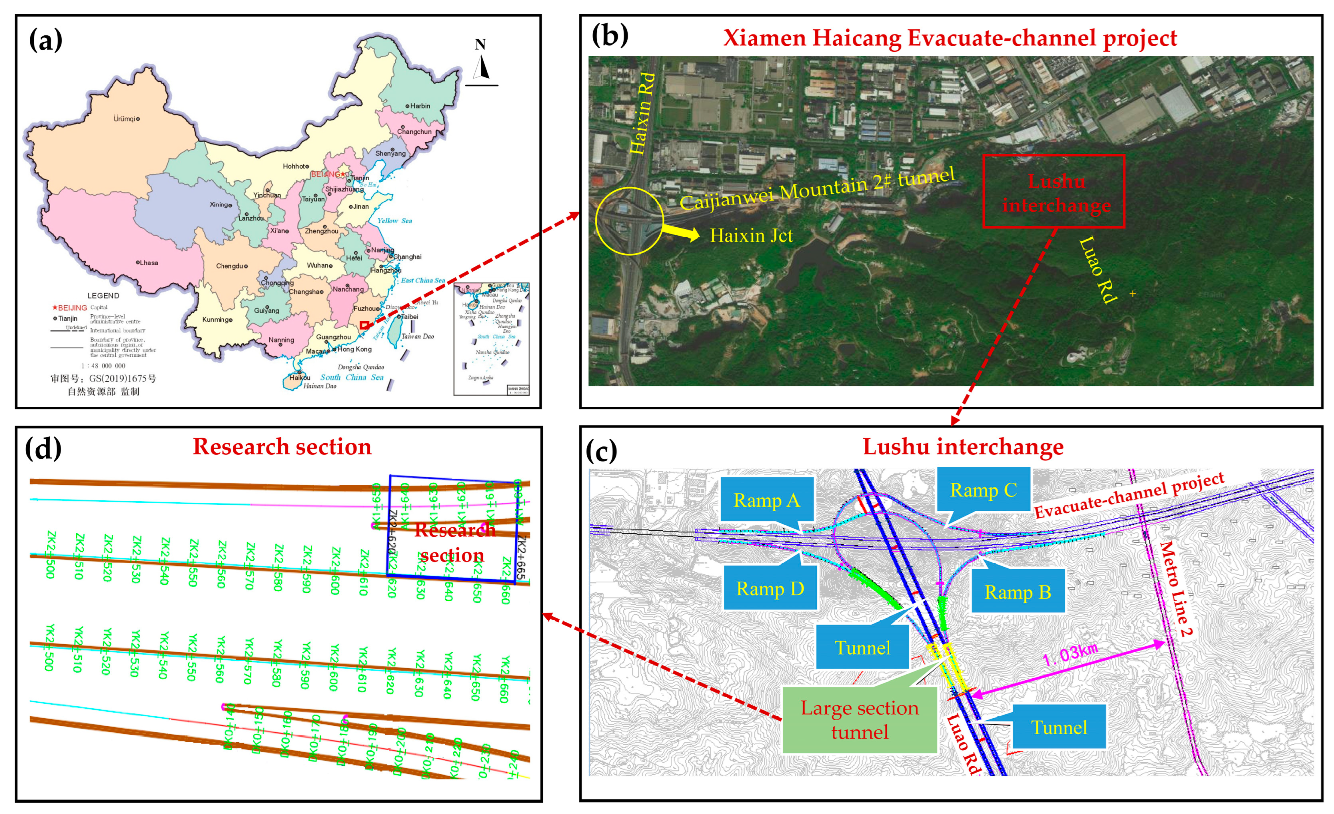
The Haicang Evacuate-channel tunnel is located in Xiamen, Fujian, China, which connects the Haixin interchange project in the west and extends to the east (Figure 1a,b). Its 2# tunnel goes through Caijianwei Mountain. The total length of the tunnel route is 5.307 km, and the road grade is an urban expressway with six two-way lanes and a design speed of 80 km/h. The tunnel is buried deep in the mountains, with a buried depth of nearly 100 m.
Figure 1c shows that the mainline 2# tunnel of the evacuate-channel and the mainline tunnel of Luao Road set up the Lushu interchange at the node of Xinmei Road, and there are four ramps, namely, A, B, C, and D, at this interchange, which are semi-interconnecting. The plane distribution of the bifurcation section is shown in Figure 1d. The research section is within the blue frame, and its pile number is ZK2 + 620 − ZK2 + 665. The research section mainly passes through the second intrusive granite strata, which is dominated by moderate weathering. It is distributed in grade III surrounding rock and belongs to relatively complete rock. The surface water in the research section is abundant, but it has little influence on tunnel construction.
In the study section, the double-side heading method was adopted to divide the large section tunnel into four parts: the left and right sidewall diversion tunnel, the upper core soil, and the lower steps. The research section was constructed by the double-side heading method, and the large section tunnel was divided into four parts: the left and right pilot tunnel, the upper core soil, and the lower bench. The maximum excavation span of the large section tunnel was 30.52 m, and the large section tunnel was divided into nine parts and excavated step-by-step. The number of rock masses was 1–9 (Figure 2). The plane coordinates of the boundary points of each excavation part are shown in Figure 2 where the coordinate origin is (0, 0). The composite lining of the large section tunnel included the first primary lining support, the second primary lining support, the I-steel frame temporary support, and the second lining concrete layer of the arch wall and inverted arch. The parameters are shown in Table 1.

3. Numerical Model

3.1. Establishment of the Three-Dimensional Numerical Model

The software Abaqus was used to establish the large section tunnel model for simulation. The influence range of the excavation stress was 3–5 times the tunnel diameter, and the boundary dimensions of the model were set as 200 m long in the X direction, 45 m long in the Z direction, and 160 m long in the Y direction. The buried depth of the tunnel was 100 m and the distance from the bottom boundary was 60 m (Figure 3a). The tunnel excavation section has a maximum excavation span of 30.52 m, a height of 17.84 m, and an excavation area of 421.73 m2. The surrounding rock, primary lining, secondary lining, and temporary support were simulated using the eight-node reduced integration solid element (C3D8R). As shown in Figure 3b,c, the excavation section of the tunnel was made up of four circles cut into a horseshoe shape. The thickness of the first primary lining solid unit was 28 cm, the thickness of the second primary lining solid unit was 20 cm, and the total thickness of the primary lining was 48 cm. The temporary support was mainly carried by I-steel, and the thickness of the solid unit was 20 cm. The thickness of the second lining solid unit was 75 cm. The model was divided by the hexahedral grid. The important positions, such as the tunnel excavation section and surrounding rock, were closely divided. The number of elements generated by the model was 26,514. Normal displacement was constrained on the front, back, sides, and bottom surfaces of the model, and no constraint was set on the top surface.

3.2. Numerical Model Parameters

The rock mass in the research section was Grade III, and the rock mass was the elastic-plastic body that conformed to the Mohr–Coulomb failure criterion. The failure criterion parameters included cohesion and internal friction angle. The lining structure was elastic, and its failure criterion parameters were the elastic modulus and Poisson’s ratio. According to the survey report, the rock mass in the research section was Grade III, and the physical and mechanical parameters of the rock mass and lining in the numerical simulation were properly adjusted by referring to the Specifications for Design of Highway Tunnels [32], as shown in Table 2.

4. Numerical Results and Discussion

4.1. Stability Analysis of Large Section Tunnel under Different Excavation Sequences

The variation in rock mass behavior caused by tunnel excavation sequence plays an important role in the construction stage [33]. Different excavation sequences affect the stress redistribution state of the surrounding rock after excavation. A reasonable excavation sequence can adjust the support parameters in a timely manner according to the stress and deformation of the surrounding rock during excavation, which is conducive to the safety and quality control of construction. While ensuring construction safety and quality, different excavation sequences also affect the footage speed. Realizing fast construction is not the only key point of construction progress control but was also the embodiment of engineering economic control. Considering that the upper rock mass must be excavated first, three working conditions of excavation sequences were set. According to the different excavation sequences of rock mass, the excavation could be divided from the right pilot tunnel to the left pilot tunnel and then to the middle pilot tunnel, from two side pilot tunnels to the middle pilot tunnel, and from the middle pilot tunnel to the two side pilot tunnels, as shown in Table 3. The numbers in the excavation sequence represent the rock mass part, as shown in Figure 2.
The double-side heading method was excavated step-by-step, and the rock mass excavation footage in each excavation step was 5 m. At every step, after the rock mass excavation is completed, the first primary support and temporary support of the excavation part in the current step and the second primary support of the excavation part in the previous step should be completed. Due to the different excavation steps and the different staggered distances of the rock mass parts, the excavation process was slightly different; Condition 1 was selected for an explanation. As shown in Table 4, Condition 1 was divided into 21 excavation steps, and the first step was to balance the initial geostress. According to the excavation sequence of the rock mass part in Table 3, the second step was to excavate rock mass part 1 and complete the first primary support and temporary support. The third step was to excavate rock mass parts 1 and 2, complete the first primary support and temporary support of the excavation part in this step, and complete the second primary support of the excavation part in the previous step. Since rock mass parts 1 and 3 should be kept 15 m apart, the fourth step was to excavate rock mass parts 1 and 2. The fifth step was to excavate rock mass parts 1, 2, and 3, complete the support, complete the support work, and so on until the whole tunnel is completed. Table 4 also shows the cumulative length of the excavation rock mass part in each excavation step as well as the distance from the face of the excavated rock mass part to the portal in each excavation step.
The tunnel in the research section was 45 m long. To reduce the influence of the longitudinal boundary effect, the section at 20 m in the Z direction was taken as the target section for analysis.

4.1.1. Analysis of Surface and Surrounding Rock Deformation

In the process of tunneling with a large section, when the excavation sequences were different, the total number of excavation steps required for tunnel penetration varied, and the displacement of the surrounding rock at the same section was also different. Figure 4 shows the vertical displacement of the surrounding rock at the target section under different working conditions when excavating the target section. The vertical displacement of the surrounding rock farther away from the tunnel was distributed in layers, indicating that the meshing was more appropriate and the calculation was reliable. In the three working conditions, the vertical displacement mode of the surrounding rock was roughly the same, showing a funnel shape. The maximum vertical displacement of the tunnel surrounding rock in three conditions was 2.601, 2.615, and 2.634 cm, respectively. The comparison of the distribution range of the maximum settlement at the vault showed that Condition 1 < Condition 2 < Condition 3. That is, for the tunnel structure, Condition 1 could restrict the distribution range of the maximum settlement better, which was conducive to construction safety.
During the excavation of the large section tunnel, the influence of the excavation of each rock mass part on the vertical displacement of the surrounding rock varied. Taking Condition 1 as an example, Figure 5 shows the influence of the excavation of the right pilot tunnel, the left pilot tunnel, the upper part of the middle pilot tunnel, and the lower part of the middle pilot tunnel on the vertical displacement of the surrounding rock at the target section. As shown in Figure 5a,b, when the right and left pilot tunnels were excavated, the surface settlement did not extend to the surrounding rock around the tunnel. After the excavation of the upper part of the middle pilot tunnel, the surface settlement extended to the surrounding rock of the tunnel Figure 5c. After the excavation of the lower part of the middle pilot tunnel, the vertical displacement of the surrounding rock of the target section is shown in Figure 5d, and the surface settlement reached half of the range of the middle tunnel, indicating that the deformation of the surrounding rock should be paid attention to during the excavation of the middle pilot tunnel.
Figure 6 shows the variation curve of the vertical surface displacement of the target section with calculation steps in various working conditions. As seen in Figure 6, after the initial ground stress balance, the surface settlement gradually increased with the advancement of the palm surface, and three stages were divided by two red vertical lines. Before the 9th step of the calculation, the left and right pilot tunnels were excavated, whereas the middle pilot tunnel was not excavated yet, and the surface settlement increased slowly. Between the 9th and 31st steps of construction, the surface settlement occurred rapidly, and more than 90% of the total settlement was completed in this stage with the gradual advancement of each face of the middle pilot tunnel. After the 31st calculation step, the ground surface settlement increased slowly with the excavation of the lower part of the middle pilot tunnel because the upper part of the rock mass excavation was completed, and the lining structure of the middle tunnel was basically completed. The final surface settlement of Conditions 1, 2, and 3 was 2.23, 2.26, and 2.32 cm, respectively. The settlement of Condition 3 was the largest, which increased by 4.04% and 2.65% compared with Conditions 1 and 2, respectively. The comparison of the three-step construction sequence could be seen as follows: Condition 3 completed the tunnel first but also the earliest to enter the surface subsidence rapid development phase. Its surface subsidence was also the largest. Condition 1 had the shortest duration in the stage of rapid surface settlement but has the most construction steps and the slowest monthly footage. Overall, Condition 2 could consider both the construction progress and surface settlement.

4.1.2. Lining Deformation Analysis

The analysis of the deformation of the lining in the tunnel structure was helpful in judging the unfavorable section in the construction process and in helping control the deformation of the surrounding rock. Figure 7 shows the vertical displacement of the primary support and temporary support in different conditions after penetrating the tunnel.
As shown in the vertical displacement distribution of the primary support in Figure 7, in the three conditions, the maximum vertical displacement was distributed in the upper area of the primary support, which was 2.007, 2.201, and 2.259 cm, respectively. The minimum vertical displacement was distributed in the lower area of the primary support, which was 0.775, 0.727, and 0.809 cm, respectively. The temporary support carried the load from the upper part of the primary support to the lower part, thereby forming a closed loop inside the section. The vertical displacement was moderate, and the maximum value was 1.765, 1.825, and 1.986 cm, respectively. In terms of the maximum vertical displacement on the upper part of the primary lining, the larger displacement was most widely distributed in Condition 2, and Condition 1 was similar to Condition 3. The lateral displacement of temporary support was small because of the constraint at the portal.
Figure 8 shows the vertical settlement variation curves of the vault at the target section in different calculation steps, and, similar to the vertical displacement of the ground surface, the vertical settlement of the tunnel vault also has a rapid development stage. Condition 1 lasted 11 calculation steps from 19 to 30, accounting for 23.9% of the total calculation steps. Condition 2 lasted 20 calculation steps from 10 to 30, accounting for 46.5% of the total calculation steps, and Condition 3 lasted 22 calculation steps from 6 to 28, accounting for 61.1% of the total calculation steps. The end time of the rapid settlement stage was close, but the duration of this section was different in various construction conditions. In the whole excavation process of the tunnel, that is, from the perspective of the time control of vault displacement, Condition 1< Condition 2< Condition 3. In the three asynchronous sequences, the vertical displacement of the vault tended to be the same after tunneling, reaching 6.3 cm.
During excavation, the horizontal displacement of the arch waist was also an important factor that affected the stability of the tunnel section. The arch waist of the right and left pilot tunnels of the target section were selected as the measuring points to analyze the horizontal displacement of the arch waist, as shown in Figure 9.
Figure 10 shows the curve of the horizontal displacement of the measuring points in each working condition as construction progresses. In Conditions 1 and 2, the right pilot tunnel was excavated first, and the lateral displacement of the arch waist tended to the surrounding rock (Figure 10a,b). In Condition 3, the horizontal displacement tended toward the inside of the tunnel at the arch waist because of the influence of the middle pilot tunnel excavation. In the previous calculation steps, a sudden change occurred in the displacement curve of the measuring point. The increasing displacement was caused by the excavation of the rock mass part close to the target measuring points, and the reduction in displacement was due to the completion of the primary lining support. When the excavation of the target section was completed, the displacement of the measuring point floated around 0 with the alternate excavation of the middle pilot tunnel and the right pilot tunnel in each condition (Figure 10a). The displacement direction of the measuring points in each condition was changing, and the variances of Conditions 1, 2, and 3 were 0.00231, 0.00823, and 0.0157, respectively. The same phenomenon also existed in Figure 10b, and the variances of the three working conditions were 0.00272, 0.00699, and 0.01129. When the tunnel section was excavated, Condition 1 better controlled the horizontal displacement of the arch waist and would not produce a large horizontal displacement change value. When the tunnel was transfixed, the horizontal displacement values at the arch waist of the target section tended to be consistent, and the sudden increase in the horizontal displacement in the later stages of each working condition was caused by the disassembly of temporary support, which led to the lack of horizontal bearing capacity in the tunnel and the lateral movement of the surrounding rock.
In terms of the lining deformation, Condition 1 not only maintained a short period of rapid settlement on the vault settlement but also avoided large horizontal displacement changes at the arch waist, which was beneficial to lining deformation.

4.1.3. Stress Analysis of Lining

In tunnel excavation, the stress characteristics of the lining were important factors that affected the bearing performance of the supporting structure. The analysis of the state of the supporting structure was helpful in judging the position of unfavorable stress and guiding construction. Figure 11 and Figure 12 show the vertical stress of the primary support and temporary support under different conditions after tunnel penetration. The positive value in the figure is tensile stress, and the negative value is compressive stress.
In Figure 11, the vertical stress distribution of the primary support was similar because of the excavation process from the right pilot tunnel to the middle pilot tunnel in Conditions 1 and 2, whereas some differences in the vertical stress distribution were observed in the excavation process from the middle pilot tunnel to the left and right pilot tunnels in Condition 3. Stress concentration occurred at the vault under the three conditions, among which Conditions 1 and 2 were tensile stress concentrations. Although Condition 2 had a wider distribution range, its value was smaller than that of Condition 1. Therefore, special attention should be paid to the construction quality of concrete at the vault in the construction of Condition 1 to prevent the occurrence of cracks. The compressive stress concentration appeared at the vault under Condition 3. Due to the strong compressive capacity of concrete, the construction under Condition 3 was conducive to the stress stability of vault concrete. In the three conditions, the maximum vertical tensile stress of the primary support was 5.688, 4.563, and 4.195 MPa, and the maximum vertical compressive stress was 20.89, 22.23, and 11.59 MPa, respectively. Figure 12 shows that the temporary support at the left and right side walls of Conditions 1 and 2 distributed downward stress, whereas the middle temporary support that separates the upper and lower tunnels was squeezed by the primary support of the left and right pilot tunnels, and the upward stress was distributed. Meanwhile, due to the limitation of boundary conditions, the local stress concentration occurred at the entrance and exit of the portal in Conditions 1 and 3, and the exit portal was subjected to tension, which was an unfavorable position. In the three conditions, the maximum vertical tensile stress of the temporary support was 11.87, 11.15, and 15.35 MPa, and the maximum vertical compressive stress was 7.19, 8.21, and 12.50 MPa, respectively.
Figure 13 and Figure 14 demonstrate the horizontal stress of the primary support and temporary support under different conditions after tunnel transfixion. Figure 13 shows that the horizontal stress distribution of the primary support in Conditions 1 and 2 was consistent, and the negative horizontal stress was distributed at the vault, that is, the compressed state, which was a favorable state. In Condition 3, the positive horizontal stress was distributed at the vault in the primary support, that is, the tensile state, which was not conducive to the performance of concrete. Figure 14 depicts that in the large range of Conditions 1, 2, and 3, the temporary support mainly distributed the tensile horizontal stress, but the I-beam could play a more significant bearing role in the temporary support.
In terms of the stress of the supporting structure, the construction of Condition 3 was more conducive to the bearing performance of the concrete at the vault. However, Condition 3 was affected by tension at the arch waist, which was an unfavorable position. On the contrary, Conditions 1 and 2 can protect the safety of concrete at the arch waist better but were affected by the tension at the vault.

4.2. Analysis of the Influence of the Second Primary Lining Supporting Timing on the Stability of Large Section Tunnel

The primary support of the tunnel structure was set in two layers. Generally, in the process of tunnel excavation, the first primary lining should be carried out quickly after completing the excavation of the tunnel face. The reasonable support timing of the second primary lining was conducive to the continuous bearing performance of the second primary support after the first primary support was carried out together with the surrounding rock. To study the influence of the support timing of the second primary lining on the stability of the large section tunnel, the stress and deformation of the lining were analyzed according to the support timing of different second primary linings. Considering that the second primary support was an important link in the process of tunnel construction and excavation, the bearing performance should be brought into play as soon as possible. Two working conditions were set (Table 5). Similarly, the section at 20 m in the Z direction was selected as the target section for analysis.

4.2.1. Deformation Analysis of Surrounding Rock

Figure 15 shows the vertical displacement of the surrounding rock at the target section in the two working conditions at the time of excavation to the target section. The influence of the two working conditions on the vertical displacement of the surrounding rock was the same. The vertical displacement of the two working conditions was relatively close because the rock mass parameters and excavation steps were consistent. The maximum vertical displacement of surrounding rock in Condition 1 and 2 was 2.631 and 2.620 cm, respectively. However, the comparison of the displacement at the tunnel vault shows that the blue area with the same value as Condition 1 had a smaller distribution range in Condition 2 and was separated from the vault by a layer of the light blue area. In other words, when the two working conditions were excavated to the same length, the vertical displacement of Condition 2 was smaller and was conducive to settlement control during construction.
Figure 16 shows the horizontal displacement of the surrounding rock at the target section under two working conditions when tunneling reached the target section. Figure 16b illustrates that the surrounding rock around the tunnel and near the surface had consistent horizontal displacement in a large range with a trend of left displacement. As shown in Figure 16a, a horizontal displacement trend to the right was observed at the arch waist of the right pilot tunnel and the upper and lower parts of the middle pilot tunnel. An opposite horizontal displacement was also observed in local areas. The maximum horizontal displacement of the surrounding rock in Condition 1 and 2 was 0.8500 and 0.8866 cm, respectively.
In terms of the overall displacement of surrounding rock, in the tunneling process, the vertical and horizontal displacements of the surrounding rock were better controlled under Condition 2, and the horizontal displacement of the surrounding rock around the tunnel was relatively uniform. Compared with Condition 1, the support interval between the first and second primary linings in Condition 2 was shorter, and the two primary linings could work together more appropriately to effectively control the displacement of the surrounding rock.

4.2.2. Stress Analysis of The Second Primary Support

Figure 17 and Figure 18 show the vertical stress of the second primary lining and temporary support at different supporting timing. Figure 17 indicates that the difference in the vertical stress distribution between the two working conditions was mainly at the vault and the arch bottom. In Condition 2, a large tensile stress range was observed at the vault. At the arch bottom, the tension range of Condition 2 was large. In the two conditions, the maximum vertical tensile stress of the second primary lining was 3.184 and 2.238 MPa, and the maximum vertical compressive stress was 11.29 and 12.63 MPa, respectively. It can be seen in Figure 18 that the temporary support had stress concentrations at the entrance and exit of the portal and the connection position with the primary lining. It also bore the extrusion effect of the inward deformation of the primary lining as a whole. The overall safety was good because the temporary support was a steel element. In the two conditions, the maximum vertical tensile stress of the temporary support was 10.29 and 5.771 MPa, and the maximum vertical compressive stress was 6.748 and 9.145 MPa, respectively.
Figure 19 shows the horizontal stress of the second primary lining in different support timing. The distribution difference of the horizontal stress of the second primary lining was mainly from the arch waist to the arch bottom. For the arch waist, the horizontal stress distribution of Condition 1 was relatively uniform and negative, that is, the secondary primary concrete lining of the arch waist was compressed. The horizontal stress of Condition 2 at the arch waist was smaller than that of Working Condition 1, which was beneficial to the bearing performance of the concrete. At the position of the arch bottom, the horizontal stress distribution in both conditions was positive, that is, the concrete at the position of the arch bottom was subjected to tensile stress, and the bottom tensile force in Condition 2 was greater than that in Condition 1. In terms of the overall stress of the second primary support, the supporting timing of Condition 1 was favorable for the primary support at the vault to bear pressure, whereas the supporting timing of Condition 2 enabled the primary support at the arch waist to bear less horizontal stress.

4.3. Analysis of the Influence of the Timing of Temporary Support Disassembly and Secondary Lining Support on the Stability of the Large Section Tunnel

The secondary lining corresponds to the reinforced concrete lining applied in the inner side of the primary support, which forms a composite lining together with the primary support to reinforce the support, optimize the route drainage system, beautify the appearance, and facilitate the installation of communication, lighting, monitoring, and other facilities. In tunnel construction, the secondary lining is generally carried out after the surrounding rock and primary support deformation tends to be stable, and the best supporting timing for the secondary lining is 30–40 days after excavation, about 50 m away from the working face [34,35]. Considering that the large section tunnel was 45 m long and complex temporary supports were arranged in the tunnel, the dismantling of the temporary supports and the timing of the secondary lining support during the progress of the section affected the stability of the tunnel section. To study the influence of the timing of temporary support disassembly and secondary lining support on the stability of the large section tunnel, two working conditions were set (Table 6). Similarly, the section at 20 m in the Z direction was selected as the target section for analysis.

4.3.1. Deformation Analysis of Lining

The displacement of the target section lining during the removal of the temporary support and secondary lining construction in two working conditions was analyzed. Figure 20 shows the vertical displacement of the lining after the removal of the temporary support, and Figure 21 shows the vertical displacement of the lining after the application of the secondary lining.
Figure 20 and Figure 21 illustrate that the different conditions of removing the temporary supports and applying the secondary lining have minimal influence on the overall vertical displacement of the lining but affect the distribution range and value of the maximum displacement on the upper part of the lining. The temporary support was layered removed in Condition 2 and overall removed in Condition 1. The distribution range of the maximum vertical displacement was small in Condition 2 because its construction was performed after the deformation of the primary lining tended to be stable. However, because of layered removal, the vault subsidence value of the disturbance to surrounding rock in Condition 2 was also bigger. In terms of the scope of the disturbance of surrounding rock, Condition 2 can be constructed after the primary lining deformation was relatively stable, and the disturbance range of the surrounding rock around the vault was small because Condition 2 had the layered demolition of the temporary support compared with the overall demolition form of Condition 1. However, due to the layered demolition, the settlement value at the vault under Condition 2 was also large.
Figure 22 shows the horizontal displacement of the lining after removing the temporary support and Figure 23 shows the horizontal displacement of the lining after the application of the secondary lining. Figure 22 shows that after removing the temporary support, the horizontal displacement of the tunnel changed significantly because of the overall removal of Condition 1, and the maximum horizontal displacement of the lining reached 0.9628 mm. After no vertical support was observed in the tunnel, the concentrated horizontal displacement to the surrounding rock side occurred on both sides of the arch waist. In Condition 2, the horizontal displacement was mainly concentrated on the lateral support, while the deformation at the arch was relatively stable, and the maximum horizontal displacement of the lining was 0.7695 mm. Figure 23 indicates that the horizontal displacement distribution of the overall lining in Condition 1 was improved after the application of the second lining, and the overall deformation of the lining structure was relatively uniform, with the maximum horizontal displacement being 0.7312 mm. The lining deformation in Condition 2 was less than that in Condition 1, and the maximum horizontal displacement of the lining in Condition 2 was 0.5546 mm.

4.3.2. Stress Analysis of the Secondary Lining

The stress state of the secondary lining structure affects the maintenance and operation of the tunnel later. Figure 24 shows the vertical stress distribution of the secondary lining with complete installation after removing all the temporary supports. The vertical stress of Condition 2 was greater than that of Condition 1. In Condition 1, the secondary lining was basically in an unstressed state, indicating that the overall construction of the secondary lining was conducive to the release of stress, but the primary lining structure bore most of the load, thereby reducing the safety of the primary lining, and did not achieve the joint bearing effect of the primary and secondary linings. In Condition 2, the vertical stress distribution was relatively uniform, and the secondary lining could also bear the surrounding rock pressure together with the primary lining.
Figure 25 shows the horizontal stress of the secondary lining. The secondary lining in Condition 1 was basically in a stress-free state, which was not conducive to the safety of the primary lining structure. In Condition 2, negative horizontal stress was distributed in the secondary lining structure in a large area, which caused the secondary lining structure to be under compression, such as at the vault.
In terms of the overall stress of the secondary lining support, although Condition 1 was beneficial to the stress of the secondary lining structure, its primary lining bore most of the load, thereby making the secondary lining too conservative. In Condition 2, the timing of temporary support disassembly and secondary lining support was relatively reasonable.

5. Conclusions

The influence of different excavation sequences, second primary lining support time, temporary support disassembly, and secondary lining support time of the double-side heading method on large section tunnel stability were analyzed, and the following conclusions were drawn:
  • In the double-side heading method, the excavation sequence from the right pilot tunnel to the left pilot tunnel and then to the middle pilot tunnel was the most conservative as its surface settlement was small. This method had a good control effect on the horizontal displacement of tunnel lining at the arch waist. The excavation sequence from both sides to the pilot middle tunnel can protect the concrete safety at the arch waist better, but tensile stress also occurred at the vault. The construction from the middle pilot tunnel to both sides was conducive to the bearing performance of the concrete at the arch crown but produces tensile stress at the arch waist.
  • The second primary lining supporting time was recommended to rapidly support the second primary lining after the excavation of the current tunnel face because the vertical displacement of the surrounding rock in this condition was small. This method was conducive to controlling the horizontal displacement at the arch waist so that the primary support at the arch waist bore small horizontal stress. The method of supporting the second primary lining of the current tunnel face and the first primary lining of the next tunnel face simultaneously was conducive to controlling the vertical settlement at the vault.
  • The method of temporary support layered disassembly and secondary lining layered support was relatively reasonable because it could effectively control the horizontal displacement of the secondary lining and exerted the bearing capacity of the arch waist concrete. The method of removing the whole temporary support and applying the whole secondary lining caused a large displacement at the arch waist, which did not benefit the safety of the primary lining structure.
  • The excavation sequence, second primary lining support time, temporary support removal, and secondary lining support time should be adjusted according to the actual deformation and stress of the section on site when the double-side heading method is adopted for the construction of large section tunnels.
  • Further study should focus on the extent of yielding zones following each excavation step and the influence of bolt length and lining support thickness on the stability of the surrounding rock.

Author Contributions

Conceptualization, J.W.; methodology, J.W. and Z.W.; software, Z.W.; validation, L.L., Z.L., J.W., Y.L., A.C., H.L., Y.S. and X.L.; formal analysis, J.W. and Z.W.; investigation, J.W., X.L., A.C., H.L., and Y.S.; resources, J.W.; data curation, Z.W.; writing—original draft preparation, J.W., Z.W., and A.C.; writing—review and editing, J.W. and A.C.; project administration, L.L. and Z.L. All authors have read and agreed to the published version of the manuscript.

Funding

This research was funded by the Shanghai Municipal Science and Technology Project (18DZ1201301; 19DZ1200900); the Xiamen Road and Bridge Group (XM2017-TZ0151; XM2017-TZ0117); the project of Key Laboratory of Impact and Safety Engineering (Ningbo University), Ministry of Education (CJ202101); the Shanghai Municipal Science and Technology Major Project (2021SHZDZX0100) and the Fundamental Research Funds for the Central Universities; the Key Laboratory of Land Subsidence Monitoring and Prevention, Ministry of Natural Resources of the People’s Republic of China (No. KLLSMP202101; KLLSMP202201); the Suzhou Rail Transit Line 1 Co., Ltd. (SURT01YJ1S10002); and the China Railway 15 Bureau Group Co., Ltd. (CR15CG-XLDYH7-2019-GC01).

Institutional Review Board Statement

The study did not require ethical approval.

Informed Consent Statement

The study did not involve humans.

Data Availability Statement

The data presented in this study are available on request from the corresponding author.

Conflicts of Interest

The authors declare no conflict of interest.

References

  1. Li, S.C.; Wang, J.H.; Chen, W.Z.; Li, L.P.; Zhang, Q.Q.; He, P. Study on mechanism of macro failure and micro fracture of local nearly horizontal stratum in super-large section and deep buried tunnel. Geomech. Eng. 2016, 11, 253–267. [Google Scholar] [CrossRef]
  2. Wu, S.L.; Yang, S.H.; Zhang, X.W. Instability mechanism of surrounding rock for super-large cross section at high-speed railway tunnel portal. Adv. Civ. Ind. Eng. 2013, 353–356, 1597–1603. [Google Scholar] [CrossRef]
  3. Chen, Q.N.; Zhao, L.J.; Xie, X.Y.; He, C.B.; Cao, Y.J. Reasonable distance for super-large section neighborhood tunnel of granite residual soil with shallow-buried bias. J. Cent. South Univ. (Sci. Technol.) 2015, 46, 3475–3480. [Google Scholar] [CrossRef]
  4. Liu, C.; Li, S.C.; Zhou, Z.Q.; Li, L.P.; Wang, K.; Hou, F.J.; Qin, C.S.; Gao, C.L. Model test on mechanical characteristics of surrounding rock during construction process of super-large section tunnel in complex strata. Rock Soil Mech. 2018, 39, 3495–3504. [Google Scholar] [CrossRef]
  5. Zuo, Q.J.; Wu, Y.Y.; Yan, T.X. Analysis of time-space effect for surrounding rock deformation in super-largecross section slate tunnel during construction period. J. Disaster Prev. Mitig. Eng. 2018, 38, 233–243. [Google Scholar] [CrossRef]
  6. Li, L.P.; Li, S.C.; Zhao, Y.; Wang, H.P.; Liu, Q.; Yuan, X.S.; Zhao, Y.; Zhang, Q. Spatial deformation mechanism and load release evolution law of surrounding rock during construction of super-large section tunnel with soft broken surrounding rock masses. Chin. J. Rock Mech. Eng. 2012, 31, 2109–2118. (In Chinese) [Google Scholar] [CrossRef]
  7. Wen, Y.M.; Zhang, J.R.; Wu, J.; Gao, Y. Ground settlement of new artificial filling soil layer induced by constructing tunnel with super large cross-section and its control measures. China Railw. Sci. 2017, 38, 79–86. [Google Scholar] [CrossRef]
  8. He, C.; Feng, K.; Yang, X. Model test on segmental lining of Nanjing Yangtze river tunnel with super-large cross-section. Chin. J. Rock Mech. Eng. 2007, 26, 2260–2269. [Google Scholar] [CrossRef]
  9. Wang, L. Study of the construction techniques for a four-arch tunnel with a super-large section. Mod. Tunn. Technol. 2016, 53, 170–176. [Google Scholar] [CrossRef]
  10. He, P.; Li, S.C.; Li, L.P.; Xu, Z.H.; Shi, S.S.; Chen, Y.J. Discontinuous deformation of surrounding rock for small-space tunnel with super-large section in jointed rock mass. Chin. J. Geotech. Eng. 2018, 40, 1889–1896. [Google Scholar] [CrossRef]
  11. Liu, J.G.; Ma, B.S.; Cheng, Y. Design of the Gongbei tunnel using a very large cross-section pipe-roof and soil freezing method. Tunn. Undergr. Space Technol. 2018, 72, 28–40. [Google Scholar] [CrossRef]
  12. Li, W.H.; Zhao, D.J.; Zhou, S.S. Numerical Simulation Analysis and Engineering Applications on the Double-Side-Wall Heading Step Bench Excavation of Large-Cross Section and Shallow Tunnel. Adv. Mater. Res. 2012, 594–597, 1182–1187. [Google Scholar] [CrossRef]
  13. Wu, B.; Huang, W. Optimization of sequential excavation method for large-section urban subway tunnel: A case study. Adv. Mech. Eng. 2020, 12, 168781402095718. [Google Scholar] [CrossRef]
  14. Zhang, Y.T.; Jin, X.G.; Dai, Y.J.; Li, H.L.; Yang, G.Y. Calculation of surrounding rock pressure of large section underground excavation metro station based on the construction process. IOP Conf. Ser. Earth Environ. Sci. 2021, 626, 012009. [Google Scholar] [CrossRef]
  15. Xu, C.B.; Xia, C.C.; Wang, H.L. The study on a new loads calculation method of multi-arch and extra large cross section tunnels. Appl. Mech. Mater. 2011, 94–96, 1159–1165. [Google Scholar] [CrossRef]
  16. Mori, K.; Abe, Y. Large rectangular cross-section tunneling by the multi-micro shield tunneling (MMST) method. Tunn. Undergr. Space Technol. 2005, 20, 129–141. [Google Scholar] [CrossRef]
  17. Wu, K.; Yu, Y.L.; Cui, S.S.; Zhang, Q.J. Construction mechanical mechanism of shallow subway tunnel group with large-span variable cross section. Geotech. Geol. Eng. 2018, 36, 3879–3891. [Google Scholar] [CrossRef]
  18. Li, J.K.; Yan, B.W.; Shi, Y.J. The monitoring and analysis of surface subsidence of soft soil rock large section of subway tunnel shield construction. Adv. Mater. Res. 2013, 848, 78–82. [Google Scholar] [CrossRef]
  19. Liu, C.; Peng, L.M.; Lei, M.F.; Li, Y.F. Research on crossing tunnels’ seismic response characteristics. KSCE J. Civ. Eng. 2019, 23, 4910–4920. [Google Scholar] [CrossRef]
  20. Zhou, D.H.; Cao, L.Q.; Ma, Y.F.; Shi, Z. Influence analysis of core rock construction in super large section and span tunnel. In Modelling and Computation in Engineering; CRC Press: Boca Raton, FL, USA, 2010; pp. 1–5. [Google Scholar] [CrossRef]
  21. Zhou, D.H.; Cao, L.Q.; Fang, S.T.; Qu, H.F.; Ma, Y.F. In-situ test and 3D-effect analysis of a tunnel lining structure of large cross section. China Civ. Eng. J. 2011, 44, 136–142. [Google Scholar] [CrossRef]
  22. Liang, B.; Zhao, F.B.; Ren, Z.D.; Zhang, Q.S.; Li, G.G. Analysis on seismic response of a super-large section tunnel in highway. Chin. J. Undergr. Space Eng. 2020, 16, 243–248. [Google Scholar]
  23. Chen, X.M.; Gao, J.H. Design of Secondary High-Capacity Support to Large-Section Tunnel with Fractured Surrounding Rock Excavated on High-Stress Condition. Trans. Beijing Inst. Technol. 2012, 32, 565–570. [Google Scholar] [CrossRef]
  24. Lu, J.F.; Wang, M.N.; Jia, Y.Y.; Yu, Y.; Tan, Z.S. Research on construction time of secondary lining of large section loess tunnel for high-speed railway. Rock Soil Mech. 2011, 32, 843–848. [Google Scholar] [CrossRef]
  25. Jiang, F.G.; Bai, L.L.; Song, M.; Wang, L.T.; Tan, X.T. Analysis on construction stability of large section tunnel of harbin city metro. J. Jilin Univ. (Eng. Technol. Ed.) 2020, 50, 1419–1427. [Google Scholar] [CrossRef]
  26. Sun, Z.J. Numerical analysis of construction method in shallow-buried large-section loess tunnel. Appl. Mech. Mater. 2014, 580–583, 997–1000. [Google Scholar] [CrossRef]
  27. Yuan, Y.; Wang, S.H.; Du, G.Q.; Li, D. In-situ testing study on lining system of double-arched tunnel. Chin. J. Rock Mech. Eng. 2005, 24, 480–485. [Google Scholar] [CrossRef]
  28. Gao, F.; Tan, X.K. Stability Analysis on Large Section Tunnel with Double-Side-Drift Method. J. Chongqing Jiaotong Univ. (Nat. Sci.) 2010, 29, 363–366+440. [Google Scholar]
  29. Yang, Y.B.; Liu, M.G.; Zhang, G.H.; Li, Q. Analysis of construction parameter optimization for new large cross-section tunnel next to existing tunnels. Rock Soil Mech. 2010, 31, 1217–1226. [Google Scholar] [CrossRef]
  30. Wang, C.; Su, Z.M. Study on optimization of core pillar in large-span tunnel excavated with double-side heading method. Adv. Mater. Res. 2011, 261–263, 1882–1885. [Google Scholar] [CrossRef]
  31. Cui, Z.D. Stability analysis of excavation of intermediate diaphragm wall in large cross-section metro station constructed by double-side-drift method and its key technologies. Tunn. Constr. 2017, 37, 1140–1145. [Google Scholar] [CrossRef]
  32. Industrial Standard of the People′s Republic of China. Specifications for Design of Highway Tunnels Section 1 Civil Engineering: JTG 3370. 1-2018; China Communications Press: Beijing, China, 2018. [Google Scholar]
  33. Rehman, H.; Najia, A.M.; Ali, W.; Junaid, M.; Abdullah, R.A.; Yoo, H.K. Numerical evaluation of new Austrian tunneling method excavation sequences: A case study. Int. J. Min. Sci. Techno. 2020, 30, 381–386. [Google Scholar] [CrossRef]
  34. Wang, Y.C.; Shang, Y.Q.; Sun, H.Y.; Li, H.Q.; Xu, X.H. Study on mechanical rules of double-lining in creeping surrounding rock. Hydrogeol. Eng. Geol. 2010, 37, 49–54. [Google Scholar] [CrossRef]
  35. Wang, W.Z.; Liang, Q.G.; Jia, G.Y.; Shi, B.D. Statistical Analysis of the Contact Pressure between the Primary Support and the Secondary Lining of Tunnel. Chin. J. Undergr. Space Eng. 2021, 17, 1586–1597. [Google Scholar]
Figure 1. Research section overview: (a) Location of Xiamen Haicang; (b) Location of Xiamen Haicang Evacuate-channel project; (c) Diagram of Lushu interchange; and (d) Schematic of research section.
Applsci 13 00406 g001
Figure 2. Schematic of the double-side heading method (unit: m).
Applsci 13 00406 g002
Figure 3. The numerical calculation model: (a) The whole calculation model; (b) Tunnel excavation rock mass; and (c) Tunnel lining.
Applsci 13 00406 g003
Figure 4. The vertical displacement of surrounding rock from excavation to target section (unit: m): (a) Condition 1; (b) Condition 2; and (c) Condition 3.
Applsci 13 00406 g004
Figure 5. Vertical displacement of surrounding rock at the target section of rock mass part excavation under Condition 1 (unit: m): (a) Excavation of the right pilot tunnel; (b) Excavation of the left pilot tunnel; (c) Excavation of the upper part of the middle pilot tunnel; (d) Excavation of the lower part of the middle pilot tunnel.
Applsci 13 00406 g005aApplsci 13 00406 g005b
Figure 6. The variation curve of vertical surface displacement of the target section with calculation steps.
Applsci 13 00406 g006
Figure 7. The vertical displacement of the primary support and temporary support in different conditions (unit: m): (a) Condition 1; (b) Condition 2; and (c) Condition 3.
Applsci 13 00406 g007
Figure 8. The vertical settlement variation curve of the vault at the target section in different calculation steps.
Applsci 13 00406 g008
Figure 9. The measuring points of horizontal displacement.
Applsci 13 00406 g009
Figure 10. The curve of horizontal displacement of the arch waist with construction steps: (a) Measuring point 1; (b) Measuring point 2.
Applsci 13 00406 g010
Figure 11. The vertical stress of the primary support in different conditions (unit: Pa): (a) Condition 1; (b) Condition 2; and (c) Condition 3.
Applsci 13 00406 g011
Figure 12. The vertical stress of the temporary support in different conditions (unit: Pa): (a) Condition 1; (b) Condition 2; and (c) Condition 3.
Applsci 13 00406 g012
Figure 13. The horizontal stress of the primary support in different conditions (unit: Pa): (a) Condition 1; (b) Condition 2; and (c) Condition 3.
Applsci 13 00406 g013
Figure 14. The horizontal stress of the temporary support in different conditions (unit: Pa): (a) Condition 1; (b) Condition 2; and (c) Condition 3.
Applsci 13 00406 g014
Figure 15. The vertical displacement of surrounding rock under various conditions from excavation to target section (unit: m): (a) Condition 1 and (b) Condition 2.
Applsci 13 00406 g015
Figure 16. The horizontal displacement of surrounding rock under various conditions from excavation to target section (unit: m): (a) Condition 1 and (b) Condition 2.
Applsci 13 00406 g016
Figure 17. The vertical stress of the second primary lining in different conditions (unit: Pa): (a) Condition 1 and (b) Condition 2.
Applsci 13 00406 g017
Figure 18. The vertical stress of the temporary support in different conditions (unit: Pa): (a) Condition 1 and (b) Condition 2.
Applsci 13 00406 g018
Figure 19. The horizontal stress of the temporary support in different conditions (unit: Pa): (a) Condition 1 and (b) Condition 2.
Applsci 13 00406 g019
Figure 20. The vertical displacement of the lining after the temporary support was removed (unit: m): (a) Condition 1 and (b) Condition 2.
Applsci 13 00406 g020
Figure 21. The vertical displacement of lining after the construction of the secondary lining (unit: m): (a) Condition 1 and (b) Condition 2.
Applsci 13 00406 g021
Figure 22. The horizontal displacement of the lining after the temporary support was removed (unit: m): (a) Condition 1 and (b) Condition 2.
Applsci 13 00406 g022
Figure 23. The horizontal displacement of the lining after the construction of the secondary lining (unit: m): (a) Condition 1 and (b) Condition 2.
Applsci 13 00406 g023
Figure 24. The vertical stress of the secondary lining (unit: Pa): (a) Condition 1 and (b) Condition 2.
Applsci 13 00406 g024
Figure 25. The horizontal stress of the secondary lining (unit: Pa): (a) Condition 1 and (b) Condition 2.
Applsci 13 00406 g025
Table 1. Large section supporting structure parameters.
Name of the Supporting StructureSupport Method
Primary lining supportFirst primary lining supportC25 shotcrete 28 cm
Second primary lining supportC25 shotcrete 20 cm
Rock boltΦ25 hollow grouting anchor L500 cm
Reinforcing meshΦ8 reinforcing mesh 15 cm × 15 cm
Temporary supportI-steel trussI20b I steel frame, longitudinal spacing 75 cm
Concrete spray layerC25 concrete spray layer 24 cm
Reinforcing meshΦ8 reinforcing mesh 20 cm × 20 cm
Secondary lining supportArch wall C40 waterproof reinforced concrete 75 cm thick
Inverted archC40 waterproof reinforced concrete 75 cm thick
Table 2. Material parameters.
MaterialsDensity (kg/m3)Elastic Modulus (GPa)Poisson’s RatioCohesion (MPa)Friction Angle (°)
Surrounding rock2100–2300100.25250
Primary lining support2500300.20//
Secondary lining support250032.50.15//
Temporary support79002000.30//
Table 3. Excavation sequence condition setting.
ConditionCondition 1 (Right → Left → Middle)Condition 2 (Left and Right → Middle) Condition 3 (Middle → Left and Right)
Excavation sequence1 → 2 → 3 → 4 → 5 → 6 → 7 → 8 → 91 + 3 → 2 + 4 → 5 → 7 → 6 → 8 → 95 → 6 → 7 → 8 → 1 → 2 → 3 → 4 → 9
The excavation staggered the distance of the rock mass partsThe distance between parts 1 and 3 is 15 m. The distance of parts 1 and 2, parts 3 and 4, parts 4 and 5, parts 5 and 6, parts 6 and 7, parts 7 and 8, and parts 8 and 9 are all 5 m.The distance of parts 1 and 3, and parts 2 and 4 are all 0 m. The distance between parts 1 and 2 is 15 m. The distance of parts 4 and 5, parts 5 and 7, parts 7 and 6, parts 6 and 8, and parts 8 and 9 are all 5 m.The distance between parts 5 and 1 is 15 m. The distance of parts 5 and 6, parts 6 and 7, parts 7 and 8, parts 1 and 2, parts 2 and 3, parts 3 and 4, and parts 4 and 9 are all 5 m.
Schematic diagram Applsci 13 00406 i001 Applsci 13 00406 i002 Applsci 13 00406 i003
Table 4. Excavation sequence of Condition 1.
Excavation StepConstruction ProcessZ Coordinate of Excavation Rock Mass Part Face (m)
123456789
Step 1Initial geostress equilibrium.000000000
Step 2Excavation part 1 and complete the first primary support and temporary support.500000000
Step 3Excavation parts 1 and 2, complete the first primary support and temporary support of the excavation part in this step and complete the second primary support of the excavation part in the previous step.1050000000
Step 4Excavation parts 1 and 2, complete the first primary support and temporary support of the excavation part in this step and complete the second primary support of the excavation part in the previous step.15100000000
Step 5Excavation parts 1, 2, and 3, complete the first primary support and temporary support of the excavation part in this step and complete the second primary support of the excavation part in the previous step.20155000000
Step 6Excavation parts 1, 2, 3, and 4, complete the first primary support and temporary support of the excavation part in this step and complete the second primary support of the excavation part in the previous step.252010500000
Step 7Excavation parts 1, 2, 3, 4, and 5, complete the first primary support and temporary support of the excavation part in this step and complete the second primary support of the excavation part in the previous step.3025151050000
Step 8Excavation parts 1, 2, 3, 4, 5, and 6, complete the first primary support and temporary support of the excavation part in this step and complete the second primary support of the excavation part in the previous step.35302015105000
Step 9Excavation parts 1, 2, 3, 4, 5, 6, 7, and 8, complete the first primary support and temporary support of the excavation part in this step and complete the second primary support of the excavation part in the previous step.403525201510500
Step 10Excavation parts 1, 2, 3, 4, 5, 6, 7, 8, and 9, complete the first primary support and temporary support of the excavation part in this step and complete the second primary support of the excavation part in the previous step.4540302520151050
Step 11Excavation parts 2, 3, 4, 5, 6, 7, 8, and 9, complete the first primary support and temporary support of the excavation part in this step and complete the second primary support of the excavation part in the previous step.45453530252015105
Step 12Excavation parts 3, 4, 5, 6, 7, 8, and 9, complete the first primary support and temporary support of the excavation part in this step and complete the second primary support of the excavation part in the previous step454540353025201510
Step 13Excavation parts 3, 4, 5, 6, 7, 8, and 9, complete the first primary support and temporary support of the excavation part in this step and complete the second primary support of the excavation part in the previous step.454545403530252015
……
Step 19Excavation part 9, complete the first primary support and temporary support of the excavation part in this step and complete the second primary support of the excavation part in the previous step.454545454545454545
Step 20Remove temporary support.454545454545454545
Step 21Complete the invert and secondary lining.454545454545454545
Table 5. The second primary lining support timing.
ConditionSupporting SequenceSupporting Diagram
1The second primary lining shall be supported at the same time as the first primary lining of the next section of the tunnel face after the current tunnel face was advanced by one footage. Applsci 13 00406 i004
2The second primary lining shall be quickly supported after the excavation of the current tunnel face was completed. Applsci 13 00406 i005
Table 6. The temporary support disassembly and second lining support working conditions.
ConditionDisassembly and Support StepsSchematic Diagram of Secondary Lining Support
1After the temporary support and the second primary lining support were completed and the tunnel was penetrated, the whole temporary support was removed and the whole secondary lining support was applied. Applsci 13 00406 i006
2After the temporary support and the second primary lining support were completed and the tunnel was penetrated, the temporary support would be dismantled in layers and the secondary lining would be supported in layers. Applsci 13 00406 i007
Disclaimer/Publisher’s Note: The statements, opinions and data contained in all publications are solely those of the individual author(s) and contributor(s) and not of MDPI and/or the editor(s). MDPI and/or the editor(s) disclaim responsibility for any injury to people or property resulting from any ideas, methods, instructions or products referred to in the content.

