
Proof of Concept of Reconfigurable Solvent Vapor Sensor Tag with Wireless Power Transfer for IoT Applications

Abstract
:1. Introduction
2. Reconfigurable RFID Sensor for Detecting Solvent Vapors/Gas
2.1. Operating Principles of the Chipless RFID Sensor
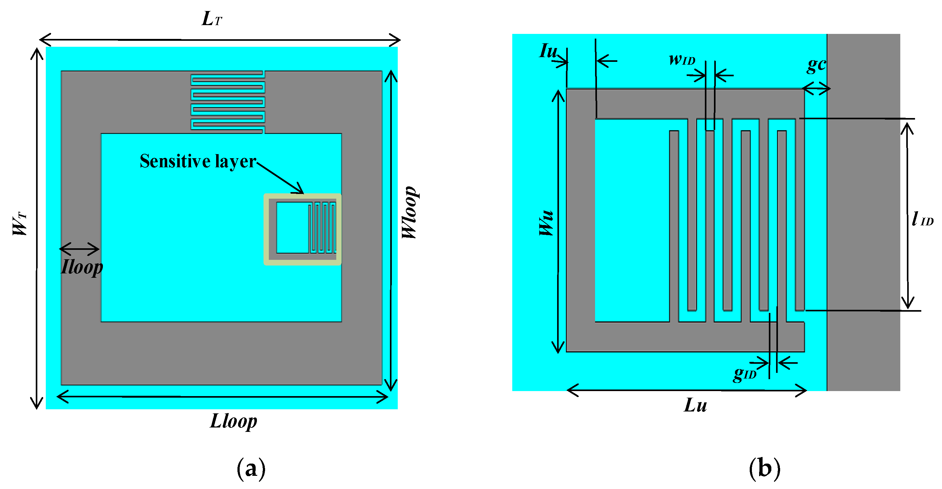
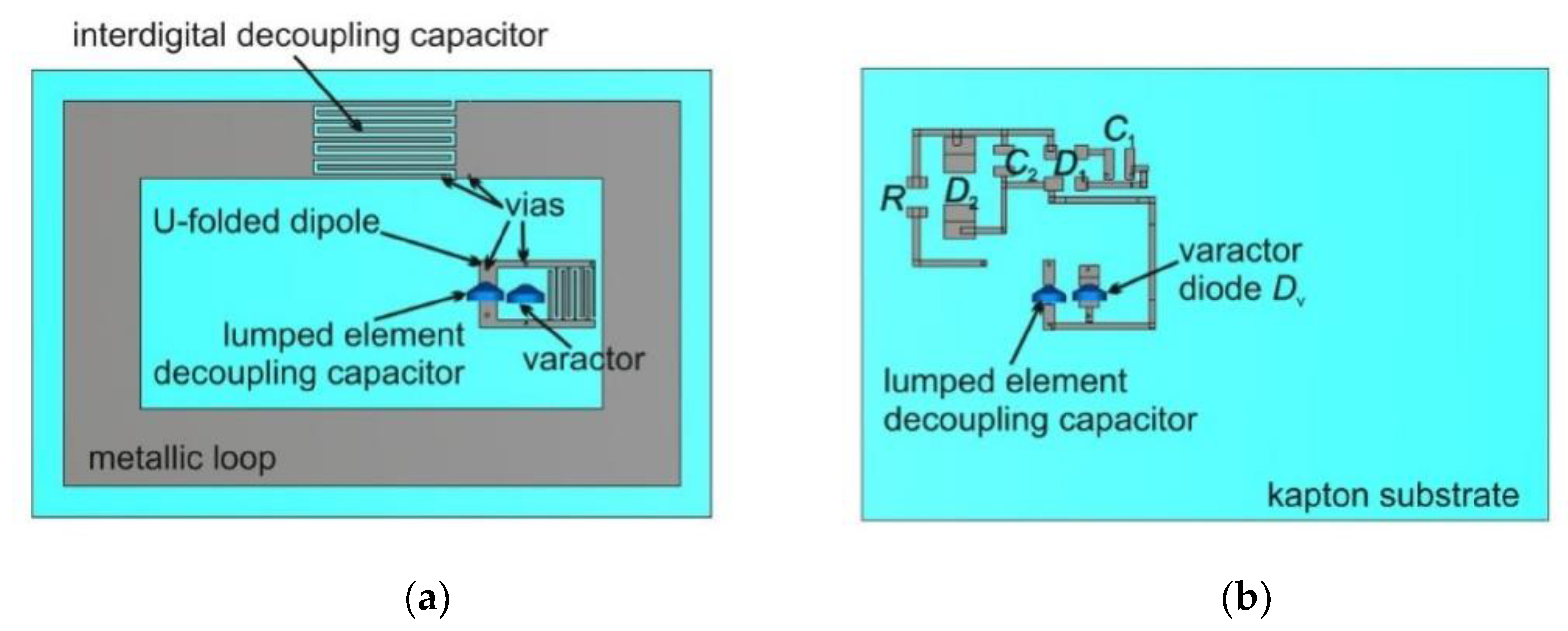
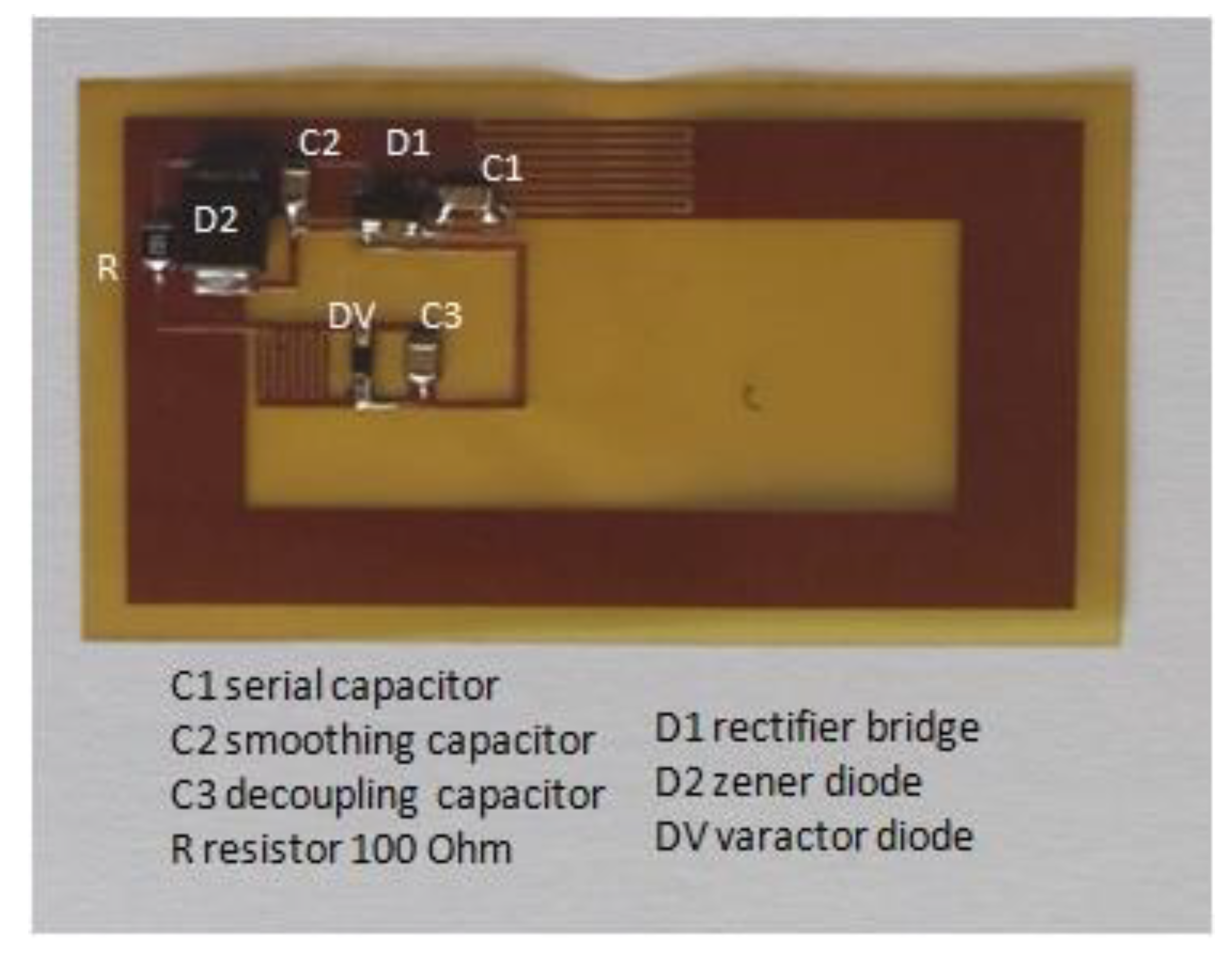
2.2. Sensor
2.3. Reconfigurable Resonant Frequency of the Sensor
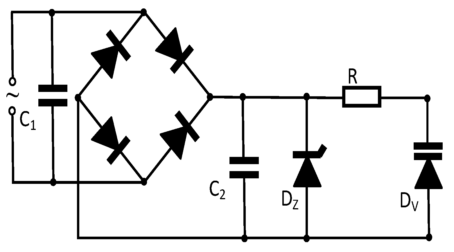
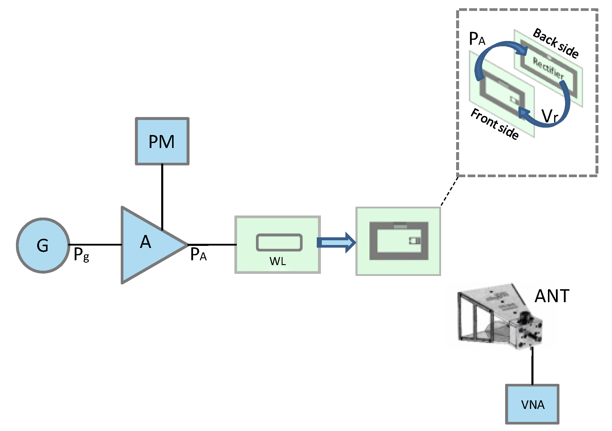
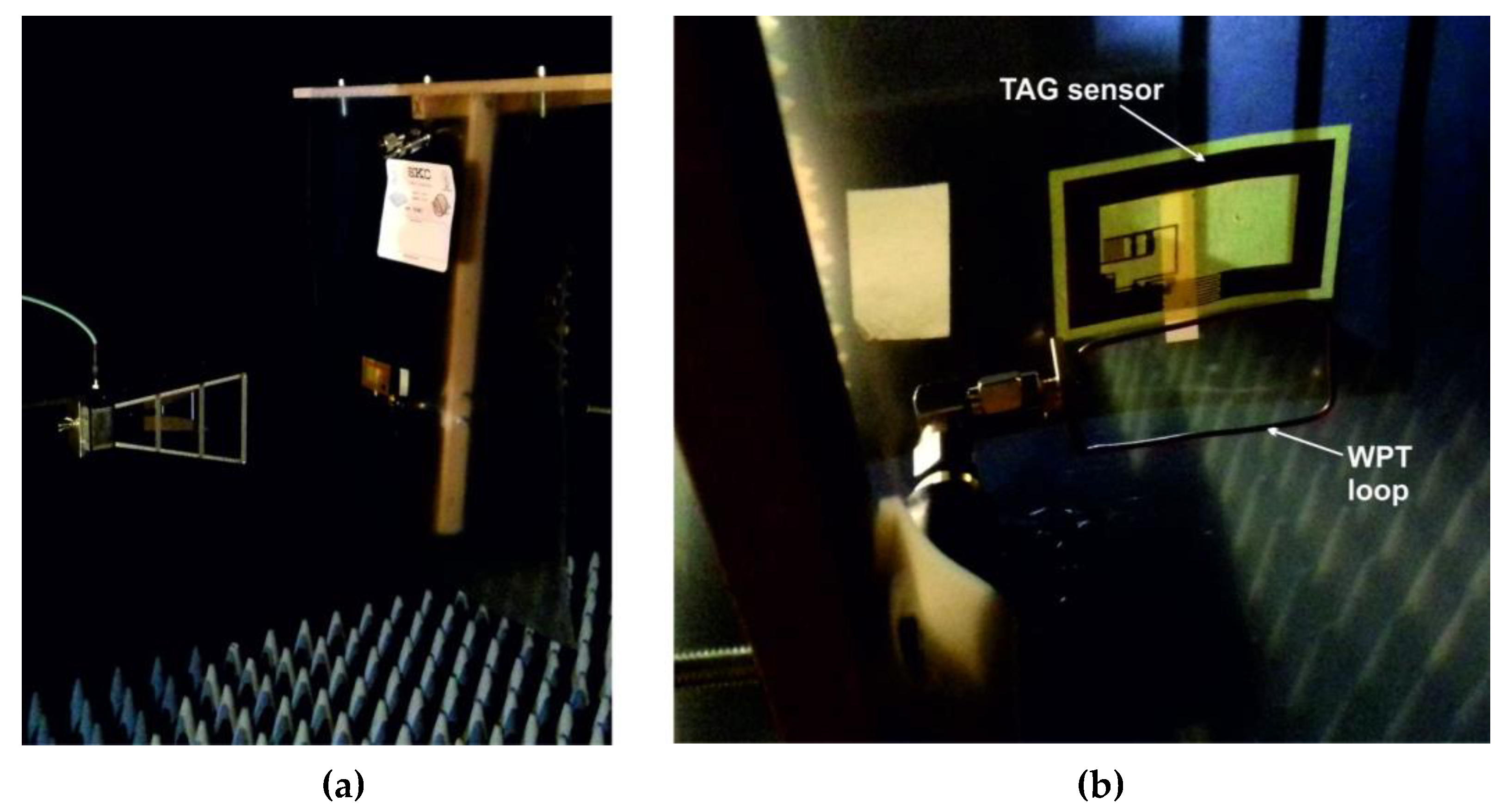
2.4. Varactor Diode Reverse Biasing
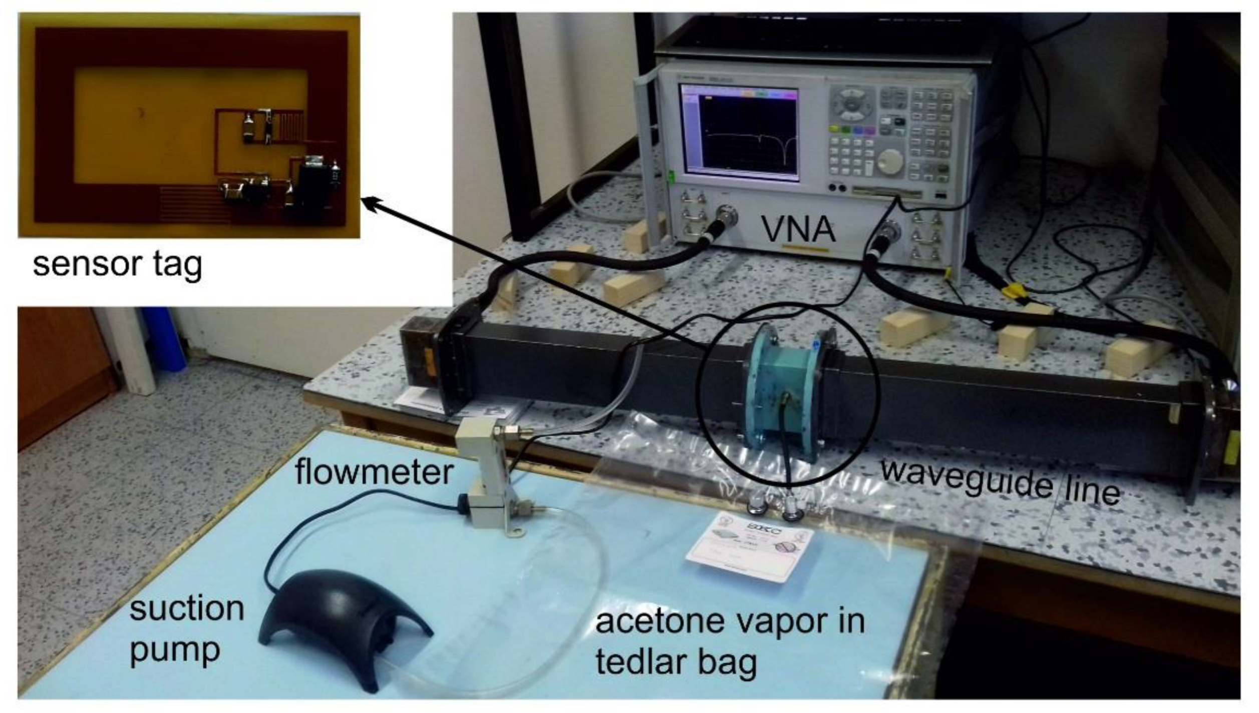
3. Results
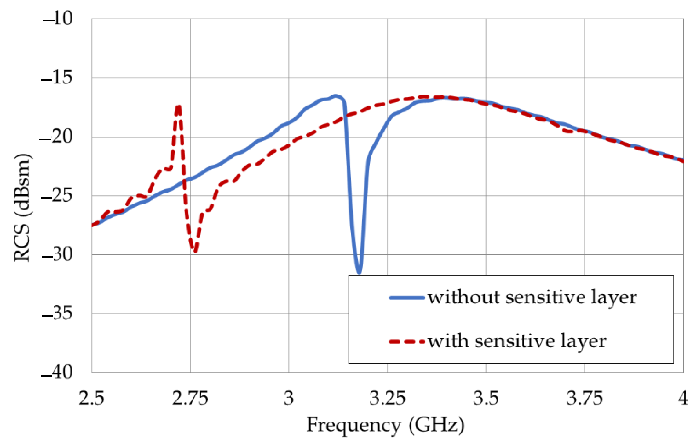
3.1. Fixed Sensor Behavior
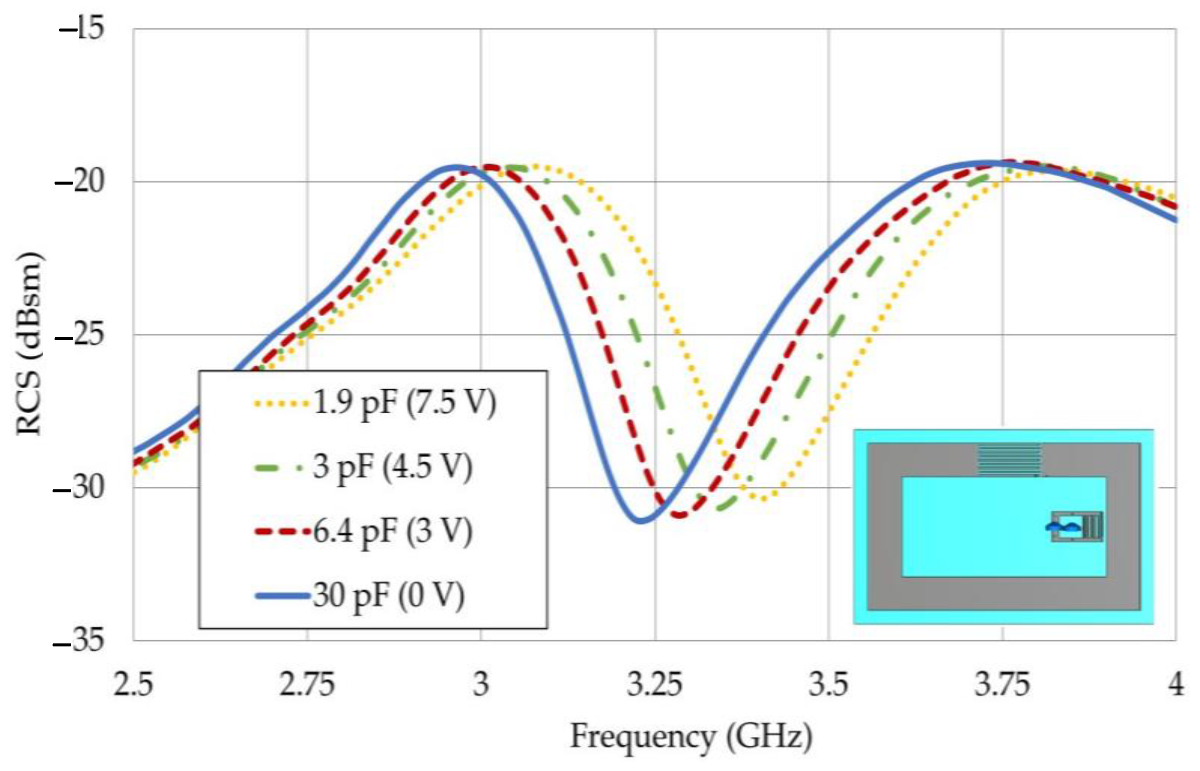
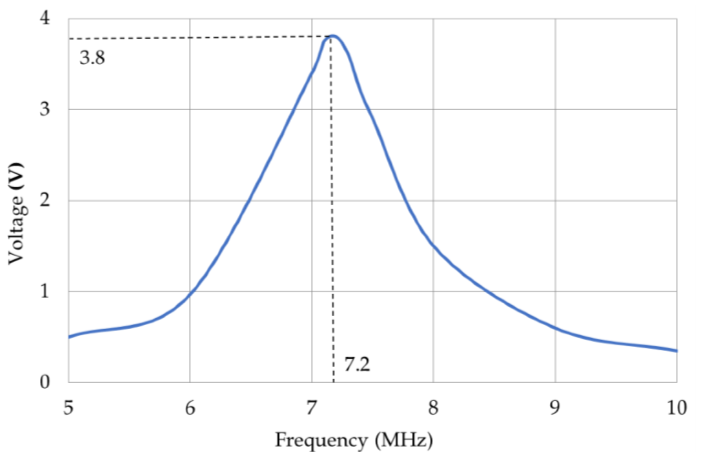
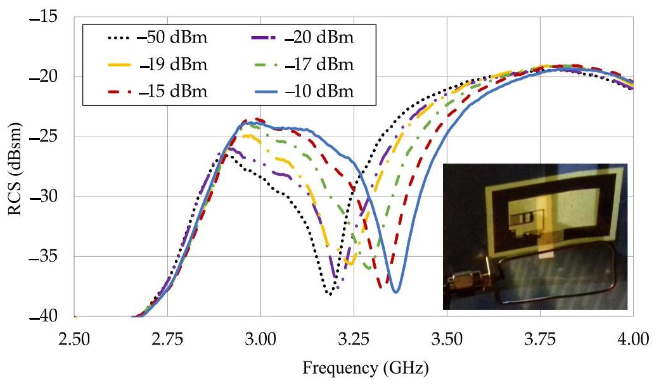
3.2. Tunable Sensor
4. Conclusions
Author Contributions
Funding
Institutional Review Board Statement
Informed Consent Statement
Data Availability Statement
Acknowledgments
Conflicts of Interest
References
- Want, R. An introduction to RFID technology. IEEE Pervasive Comput. 2006, 5, 25–33. [Google Scholar] [CrossRef]
- Tharindu, A.; Karmakar, N. Chipped versus chipless RF identification: A comprehensive review. IEEE Microw. Mag. 2019, 20, 47–57. [Google Scholar]
- Li, H.N.; Ren, L.; Jia, Z.G.; Yi, T.H.; Li, D.S. State-of-the-art in structural health monitoring of large and complex civil infrastructures. J. Civ. Struct. Health Monit. 2016, 6, 3–16. [Google Scholar] [CrossRef]
- Herrojo, C.; Mata-Contreras, J.; Paredes, F.; Martín, F. Microwave encoders for chipless RFID and angular velocity sensors based on S-shaped split ring resonators. IEEE Sens. J. 2017, 17, 4805–4813. [Google Scholar] [CrossRef] [Green Version]
- Cui, L.; Zhang, Z.; Gao, N.; Meng, Z.; Li, Z. Radio frequency identification and sensing techniques and their applications—A review of the state-of-the-art. MDPI Sens. 2019, 19, 4012. [Google Scholar] [CrossRef] [Green Version]
- Dey, S.; Saha, J.K.; Karmakar, N.C. Smart sensing: Chipless RFID solutions for the internet of everything. IEEE Microw. Mag. 2015, 16, 26–39. [Google Scholar] [CrossRef]
- Kaneko, M.; Hu, W.; Hayashi, K.; Sakai, H. Compressed sensing-based tag identification protocol for a passive RFID system. IEEE Commun. Lett. 2014, 18, 2023–2026. [Google Scholar] [CrossRef] [Green Version]
- Kracek, J.; Mazanek, M. Wireless power transmission for power supply: State of art. Radioengineering 2011, 20, 457–463. [Google Scholar]
- Team, C.A.I. Europe and the Future for WPT: European Contributions to Wireless Power Transfer Technology. IEEE Microw. Mag. 2017, 18, 56–87. [Google Scholar] [CrossRef] [Green Version]
- Kracek, J.; Svanda, M. Analysis of Capacitive Wireless Power Transfer. IEEE Access 2019, 7, 26678–26683. [Google Scholar] [CrossRef]
- Kracek, J.; Svanda, M.; Hoffmann, K. Scalar Method for Reading of Chipless RFID Tags Based on Limited Ground Plane Backed Dipole Resonator Array. IEEE Trans. Microw. Theory Tech. 2019, 67, 4547–4558. [Google Scholar] [CrossRef]
- Li, C.; Tan, Q.; Zhang, W.; Xue, C.; Xiong, J. An embedded passive resonant sensor using frequency diversity technology for high-temperature wireless measurement. IEEE Sens. J. 2014, 15, 1055–1060. [Google Scholar]
- Salmerón, J.F.; Albrecht, A.; Kaffah, S.; Becherer, M.; Lugli, P.; Rivadeneyra, A. Wireless chipless system for humidity sensing. Sensors 2018, 18, 2275. [Google Scholar] [CrossRef] [PubMed]
- Svanda, M.; Machac, J.; Polivka, M.; Havlova, S.; Fitl, P.; Vrnata, M. Chipless RFID Tag with Enhanced RCS Used as a Phthalocyanine-Based Solvent Vapors Sensor. IEEE Antennas Wirel. Propag. Lett. 2020, 19, 1556–1560. [Google Scholar] [CrossRef]
- Occhiuzzi, C.; Rida, A.; Marrocco, G.; Tentzeris, M. RFID passive gas sensor integrating carbon nanotubes. IEEE Trans. Microw. Theory Tech. 2011, 59, 2674–2684. [Google Scholar] [CrossRef]
- Hallil, H.; Chebila, F.; Menini, P.; Aubert, H. Feasibility of passive Gas sensor based on whispering gallery modes and its RADAR interrogation: Theoretical and experimental investigations. Sens. Transducers J. 2010, 116, 38–48. [Google Scholar]
- Occhiuzzi, C.; Cippitelli, S.; Marrocco, G. Modeling, design and experimentation of wearable RFID sensor tag. IEEE Trans. Antennas Propag. 2010, 58, 2490–2498. [Google Scholar] [CrossRef] [Green Version]
- Naqui, J.; Martín, F. Microwave sensors based on symmetry properties of resonator-loaded transmission lines. J. Sens. 2015, 2015, 741853. [Google Scholar] [CrossRef] [Green Version]
- Zhang, P. Design and Fabrication of Chemiresistor Typemicro/Nano Hydrogen Gas Sensors Using Interdigitated Electrodes. Ph.D. Thesis, University of Central Florida, Orlando, FL, USA, 2008. [Google Scholar]
- Ali, M.A.; Chen, M.M.C.; Chen, J.C.M.; Wu, C.T.M. Microwave gas sensor based on graphene-loaded substrate integrated waveguide cavity resonator. In Proceedings of the 2016 IEEE MTT-S International Microwave Symposium (IMS), San Francisco, CA, USA, 22–27 May 2016. [Google Scholar]
- Ebrahimi, A.; Beziuk, G.; Scott, J.; Ghorbani, K. Microwave differential frequency splitting sensor using magnetic-LC resonators. Sensors 2020, 20, 1066. [Google Scholar] [CrossRef] [Green Version]
- Rydosz, A.; Maciak, E.; Wincza, K.; Gruszczynski, S. Microwave-based sensors with phthalocyanine films for acetone, ethanol and methanol detection. Sens. Actuators B Chem. 2016, 237, 879–886. [Google Scholar] [CrossRef]
- Abbasi, Z.; Zarifi, M.H.; Shariati, P.; Hashisho, Z.; Daneshmand, M. Flexible Coupled Microwave Ring Resonators for Contactless Microbead Assisted Volatile Organic Compound Detection. In Proceedings of the 2017 IEEE MTT-S International Microwave Symposium (IMS), Honololu, HI, USA, 4–9 June 2017; pp. 1228–1231. [Google Scholar]
- Zarifi, M.H.; Sohrabi, A.; Shaibani, P.M.; Daneshmand, M.; Thundat, T. Detection of Volatile Organic Compounds Using Microwave Sensors. IEEE Sens. J. 2015, 15, 89–99. [Google Scholar] [CrossRef]
- Wiwatcharagoses, N.; Parkm, K.Y.; Chahal, P. Metamaterial-Inspired Sensor on Porous Substrate for Detection of Volatile Organic Compounds in Air. In Proceedings of the Electronic Components and Technology Conference, Las Vegas, NV, USA, 31 May–3 June 2016; pp. 1557–1562. [Google Scholar]
- Yang, F.; Qiao, Q.; Virtanen, J.; Elsherbeni, A.Z.; Ukkonen, L.; Sydanheimo, L. Reconfigurable sensing antenna: A slotted patch design with temperature sensation. IEEE Antennas Wirel. Propag. Lett. 2012, 11, 632–635. [Google Scholar] [CrossRef]
- Jiang, Z.; Yang, F. Reconfigurable sensing antennas integrated with thermal switches for wireless temperature monitoring. IEEE Antennas Wirel. Propag. Lett. 2013, 12, 914–917. [Google Scholar] [CrossRef]
- Tawk, Y.; Christodoulou, C.G. A new reconfigurable antenna design for cognitive radio. IEEE Antennas Wirel. Propag. Lett. 2009, 8, 1378–1381. [Google Scholar] [CrossRef]
- Chaabane, G.; Madrangeas, V.; Chatras, M.; Arnaud, E.; Huitema, L.; Blondy, P. High-Linearity 3-bit frequency-tunable planar inverted-F antenna for RF applications. IEEE Antennas Wirel. Propag. Lett. 2017, 16, 983–986. [Google Scholar] [CrossRef]
- Ayadi, H.; Machac, J.; Beldi, S.; Latrach, L. Planar Hexagonal Antenna with Dual Reconfigurable Notched Bands for Wireless Communication Devices. Radioengineering 2021, 30, 25–33. [Google Scholar] [CrossRef]
- Amin, E.M.; Saha, J.K.; Karmakar, N.C. Smart sensing materials for low-cost chipless RFID sensor. IEEE Sens. J. 2014, 14, 2198–2207. [Google Scholar] [CrossRef]
- Beeresha, R.S.; Khan, A.M.; Manjunath-Reddy, H.V. Design and optimization of interdigital capacitor. Int. J. Res. Eng. Technol. 2016, 5, 73–78. [Google Scholar]
- Skyworks. SMV121x Series: Hyperabrupt Junction Tuning Varactors. Available online: https://datasheet.lcsc.com/szlcsc/Skyworks-Solutions-SMV1213-001LF_C150866.pdf. (accessed on 28 July 2016).
- Kracek, J.; Svanda, M.; Mazanek, M.; Machac, J. Implantable semi-active UHF RFID tag with inductive wireless power transfer. IEEE Antennas Wirel. Propag. Lett. 2016, 15, 1657–1660. [Google Scholar] [CrossRef]
- Takhedmit, H.; Cirio, L.; Picon, O.; Vollaire, C.; Allard, B.; Costa, F. Design and characterization of an efficient dual patch rectenna for microwave energy recycling in the ISM band. Prog. Electromagn. Res. C 2013, 43, 93–108. [Google Scholar] [CrossRef] [Green Version]
- Chandravanshi, S.; Akhtar, M.J. An efficient dual-band rectenna using symmetrical rectifying circuit and slotted monopole antenna array. Int. J. RF Microw. Comput. -Aided Eng. 2020, 30, e22117. [Google Scholar] [CrossRef]
- INFINEON. BAS3007A: Low VF Schottky Diode Array. Available online: https://www.infineon.com/dgdl/Infineon-BAS3007ASERIES-DS-v01_01en.pdf?fileId=db3a3043156fd5730115a286aa19083b (accessed on 20 November 2007).
- Tomecek, D.; Hruska, M.; Fitl, P.; Vlcek, J.; Maresova, E.; Havlova, S.; Patrone, L.; Vrnata, M. Phthalocyanine photo-regeneration for low power consumption chemiresistors. ACS Sens. 2018, 3, 2558–2565. [Google Scholar] [CrossRef] [PubMed]
- Diodes 1SMB5920B—1SMB5956B: 3.0W surface mount power zener diode. Available online: https://www.diodes.com/assets/Datasheets/ds32125.pdf (accessed on 1 May 2020).
- RF Spin, DRH20: Double Ridged Waveguide Horn. Available online: https://www.rfspin.cz/en/antennas/measurement-antennas/drh20 (accessed on 2 June 2021).
- Polivka, M.; Havlicek, J.; Svanda, M.; Machac, J. Improvement in robustness and recognizability of RCS response of U-shaped strip-based chipless RFID tags. IEEE Antennas Wirel. Propag. Lett. 2016, 15, 2000–2003. [Google Scholar] [CrossRef]
- Added, M.; Boulejfen, N.; Svanda, M.; Ghannouchi, F.M.; Vuong, T.P. High-performance chipless radio-frequency identification tags: Using a slow-wave approach for miniaturized structure. IEEE Antennas Propag. Mag. 2019, 61, 46–54. [Google Scholar] [CrossRef]


| TAG (Dimensions in mm) | |||||
|---|---|---|---|---|---|
| LT | WT | Lloop | Wloop | Iloop | Lu |
| 45 | 30 | 40 | 25 | 5 | 7.3 |
| Wu | Iu | lID | wID | gID | gc |
| 4.4 | 0.5 | 3.2 | 0.2 | 0.2 | 0.5 |
| Phthalocyanine Layer Thickness (µm) | Frequency (GHz) | Δf (GHz) | Δf (%) |
|---|---|---|---|
| 0.6 µm without acetone vapor | 3.276 | 0.009 | 0.3 |
| 0.6 µm with acetone vapor | 3.285 | ||
| 1.2 µm without acetone vapor | 3.264 | 0.012 | 0.4 |
| 1.2 µm with acetone vapor | 3.276 |
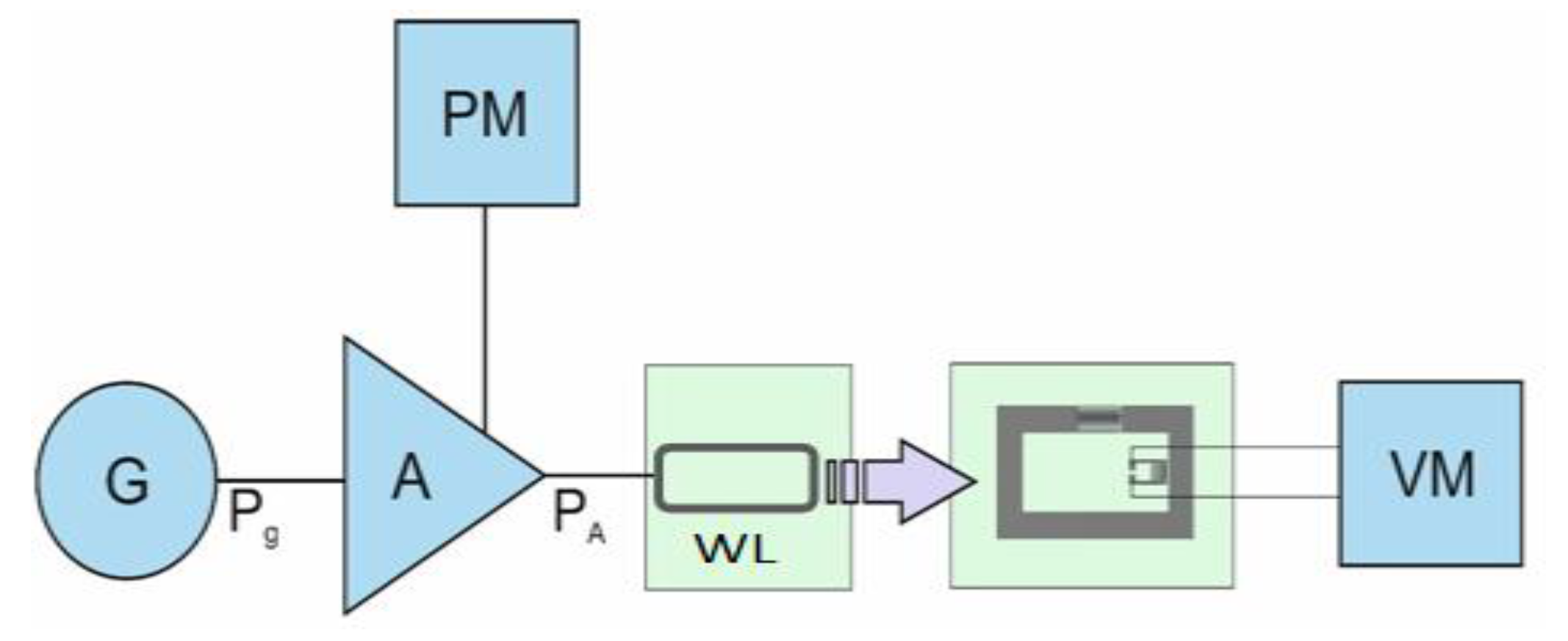
| G | Generator: Elsy SG 2000 (100 kHz–1 GHz) |
| A | Power amplifier: BONN Elektronik BSA 0101-25/30D (9 kHz–1 GHz, +46 dB) |
| PM | Power meter: Keysight (Hewlett-Packard) 437B + power sensor |
| WL | Wire loop |
| VM | Multimeter: Voltcraft M-4660A |
| # | Pg (dBm) | PA (dBm) | Vr (V) |
|---|---|---|---|
| 1 | −40 | 10.9 | 0.35 |
| 2 | −35 | 15.8 | 0.65 |
| 3 | −30 | 20.9 | 1.40 |
| 4 | −25 | 26.0 | 2.60 |
| 5 | −20 | 31.0 | 3.80 |
| 6 | −15 | 36.0 | 7.30 |
| 7 | −10 | 41.0 | 7.50 |
| 8 | −5 | 45.1 | 7.60 |
| 9 | 0 | 47.1 | 7.70 |
| VNA | Vector network analyzer: Rohde & Schwarz ZVA40 (10 MHz–40 GHz) |
| ANT | Double-ridged horn antenna: DRH20 (1.7–20 GHz) |
| # | Type of Sensor Structure | f0 (GHz) | Δf (kHz/ppm) | RCS (dBsm) | Notch (dB) | Contactless |
|---|---|---|---|---|---|---|
| 1 | [22] Microstrip line | 8.5 | 15,200 | - | - | no |
| 2 | [23] Ring resonators | 4 | 40 | −30 | 14 | 15 mm |
| 3 | [24] Split-ring reson. | 5.5 | 30 | −25 | 10 | no |
| 4 | [25] Open gap reson. | 7.4 | 17 | - | - | no |
| 5 | [14] ID U-dip in loop | 3.4 | 1.2 | −18 | 16 | 500 mm |
| 6 | This work | 3.2–3.4 sweep | 1.2 | −20 | 18 | 500 mm |
Publisher’s Note: MDPI stays neutral with regard to jurisdictional claims in published maps and institutional affiliations. |
© 2022 by the authors. Licensee MDPI, Basel, Switzerland. This article is an open access article distributed under the terms and conditions of the Creative Commons Attribution (CC BY) license (https://creativecommons.org/licenses/by/4.0/).
Share and Cite
Ayadi, H.; Machac, J.; Svanda, M.; Boulejfen, N.; Latrach, L. Proof of Concept of Reconfigurable Solvent Vapor Sensor Tag with Wireless Power Transfer for IoT Applications. Appl. Sci. 2022, 12, 10266. https://doi.org/10.3390/app122010266
Ayadi H, Machac J, Svanda M, Boulejfen N, Latrach L. Proof of Concept of Reconfigurable Solvent Vapor Sensor Tag with Wireless Power Transfer for IoT Applications. Applied Sciences. 2022; 12(20):10266. https://doi.org/10.3390/app122010266
Chicago/Turabian StyleAyadi, Houda, Jan Machac, Milan Svanda, Noureddine Boulejfen, and Lassaad Latrach. 2022. "Proof of Concept of Reconfigurable Solvent Vapor Sensor Tag with Wireless Power Transfer for IoT Applications" Applied Sciences 12, no. 20: 10266. https://doi.org/10.3390/app122010266