Article

Numerical Simulation on the Response of Adjacent Underground Pipelines to Super Shallow Buried Large Span Double-Arch Tunnel Excavation

1
College of Civil Engineering, Tongji University, Shanghai 200092, China
2
Key Laboratory of Geotechnical and Underground Engineering of Ministry of Education, Department of Geotechnical Engineering, Tongji University, Shanghai 200092, China
3
Xiamen Road and Bridge Construction Group Company Ltd., Xiamen 361026, China
*
Author to whom correspondence should be addressed.
Appl. Sci. 2022, 12(2), 621; https://doi.org/10.3390/app12020621
Submission received: 15 November 2021 / Revised: 5 January 2022 / Accepted: 6 January 2022 / Published: 10 January 2022
(This article belongs to the Special Issue Advanced Numerical Simulations in Geotechnical Engineering)

Abstract

:
The excavation of a shallow buried tunnel may cause stress redistribution in surrounding rock, and cause deformation, damage, and even destruction of adjacent underground pipelines. The land part of the Haicang undersea tunnel in Xiamen of China was a super shallow buried large span double-arch tunnel. Its construction was restricted by both underground excavation safe and adjacent pipeline protection. Multiple groups of working conditions were designed considering the relative position of pipe and tunnel, pipeline and tunnel construction parameters. Numerical simulation was used to study the influence of pipeline horizontal distance, buried depth, pipeline diameter, pipeline wall thickness, pipeline shape, pipeline material and excavation method on the response of adjacent underground pipelines. The results show that the relative position of pipe and tunnel, and the construction method of the double-arch tunnel have a great influence on pipeline deformation. Pipeline material, pipeline diameter and excavation method have a great influence on pipeline stress. The construction method was the key factor affecting the stress and deformation of the pipeline. The three-step reserved core soil method can effectively control the stress and deformation of underground pipelines. The research results can provide a reference for similar projects.

1. Introduction

When highway tunnels pass through urban areas, they often face problems such as tight land use, fragile geological environment, and high sensitivity of the surrounding environment. Therefore, it is necessary to strictly control the stress release ratio and reduce the disturbance to the surrounding rock to minimize the impact on the surrounding environment [1]. The double-arch tunnel is one of the most commonly used construction methods for urban highway tunnels because of its beautiful section, land saving and relatively small impact on the surrounding environment [2,3,4,5]. Due to a large number of underground pipelines in urban areas, the underground excavation causes stress redistribution in surrounding rock and soil, which inevitably affects the deformation of land surface and surrounding pipelines. If the pipelines were damaged or failed, not only the safety of engineering construction is threatened, but also the normal production and life of urban residents are greatly affected [6,7]. Therefore, it is of great significance to study the response mechanism of the underground pipeline to underground excavation.
Extensive researches have been conducted on the influence of underground excavation on adjacent pipelines and fruitful results have been achieved. The studies on existing pipeline deformation mainly include analytical, experimental, and numerical simulation methods. An analytical method has a rigorous derivation process and reliable mathematical basis, which can provide simple and clear solutions to engineering. Based on Winkler elastic foundation beam theory, Attewell [8] proposed an analysis and calculation model of pipeline deformation caused by stratum movement induced by tunnel excavation, and analyzed the joint angle and bending stress of the pipeline when the pipeline moved perpendicular to the parallel stratum. Klar et al. [9] obtained the modified Winkler foundation modulus by using the elastic continuum solution, so that the Winkler system and the elastic continuum system obtained similar maximum bending moments in the natural stratum settlement dimension Gaussian distribution. Vorsterl [10] studied the distribution of pipeline bending moment caused by tunnel excavation, and obtained the prediction formula of pipeline bending moment according to the geometrical shape of pipeline and tunnel and the ground movement at the same depth of the pipeline. Yoo et al. [11,12] compiled a TURISK program to calculate the strain of underground pipelines according to the stratum bending strain and axial strain caused by engineering excavation. Molnar et al. [13] studied the influence of deep foundation pit excavation on adjacent underground pipelines in Lurie medical research center in Chicago by comparing theoretical calculation with measured data. Hunter [14] deduced pipeline displacement based on stratum deformation and studied the influence of subway excavation on adjacent pipelines. Using nonlinear regression method, Ukritchon et al. [15] established the approximate equation of stability load factor and safety factor of the square tunnel in anisotropic heterogeneous clay, and also established the design equation of stability analysis of shallow buried unlined circular tunnel [16].
The tests on double-arch tunnels and pipelines included field tests and laboratory tests. Due to multi-uncontrollable factors and high cost, few studies were performed on field tests. Using the method of field measurement, Wang et al. [7] systematically studied the attenuation law of blasting seismic waves in soil and the vibration response of buried pipelines. Liu et al. [17] studied the influence of shield tunnel construction on the deformation of buried pipelines and the relationship between the deflection of pipelines and pipeline damage by analyzing the monitoring data of shield tunnel construction. Laboratory test has been widely used in the influence of tunnel excavation on adjacent pipelines because of their convenient operation, low cost and high controllability. Wham et al. [18] analyzed the response of cast iron connecting pipe and ductile iron connecting pipe to single tunnel excavation by using a laboratory model, and found that cast iron connecting pipe was a pipe type with great influence and easy damage from tunnel excavation. Using the indoor shrinkage model, Wang et al. [19] studied the development process of underground pipeline deformation and surface settlement in dry sand. Centrifugal model test can compensate for the loss of self-weight of structures caused by the reduction of model size through the acceleration field formed by the centrifugal testing machine. Shi et al. [20] used a centrifuge model test to study the response of pipelines when the tunnel crosses obliquely. Marshall et al. [21] studied the relationship between soil strain and pipe bending behavior by centrifugal model test, and obtained the relationship between tunnel volume loss, soil strain and pipe bending deformation. Kimura et al. [22] conducted a large number of centrifugal simulation tests and studied the relationship between pipeline stress and deformation and soil stress.
With the development of computer technology, finite element numerical simulation has become the main method to study the crossing problem. Using the finite-difference continuous elastic analysis method, Zhang et al. [23] simulated the response of continuous pipe and jointed pipe under tunnel-induced multi-layer soil motion. Based on finite element software, Liu et al. [24] studied the influence of the position between pipeline and tunnel on pipeline deformation. Yang et al. [25] studied the stress and displacement changes of the upper underground pipeline under the conditions of earthquake and tunnel excavation by using FLAC3D software. The three-dimensional finite element analysis model was established by using the finite-difference software, and Guo et al. [26] simulated the influence of double pipe parallel tunnel excavation with different buried depth, material properties and diameter on underground pipelines. Based on Plaxis 3D, Wang et al. [27] conducted a simulation analysis on surface settlement and pipeline deformation by using the soil hardening small strain constitutive model, and the results showed that considering the small strain stiffness of soil could predict the actual deformation of the project more reasonably. Yu et al. [28] performed numerical simulations, the results show that when the position of the municipal pipeline and subway tunnel was vertical, the displacement of the pipeline was less than the horizontal displacement, while the stress of the pipeline was opposite. Yang et al. [29] discussed the main influencing factors of the existing tunnel on the seismic performance of adjacent underground pipelines, including the joint type of the pipeline, the angle and distance between the pipeline and the tunnel. The numerical results show that the flexible joint was an important factor to reduce the settlement difference and axial stress of the pipeline. Using the formula of finite element lower limit analysis and second-order cone programming, Kumar et al. [30] estimated the support pressure required to stabilize a circular tunnel in two layers of clay under undrained conditions, and evaluated the stability of a long tunnel excavated from normally consolidated and overconsolidated saturated clay under undrained conditions [31]. Additionally, the calculation method of the minimum support pressure for the circular tunnel lining was given considering the anisotropic undrained shear strength parameter [32]. The existing research on the response of adjacent underground pipelines under tunnel excavation had considered the geometrical shape of a tunnel, the buried depth of a pipeline, the material, the size of a pipeline and the relative position with tunnel. However, seldom focused on the response of the adjacent underground pipelines to a super shallow buried large span double-arch tunnel excavation during excavation where pipeline protection was vital for tunnel construction. The analysis on the response of adjacent underground pipelines to double-arch tunnel excavation can make up for this deficiency and provide a reference for tunnel construction and underground pipeline design.
Taking the Haicang tunnel in Xiamen of China as the background, the responses of adjacent underground pipeline to the excavation of a super shallow buried large span double-arch were studied by using numerical simulation method. The influence of relative position of pipe and tunnel, pipeline and tunnel construction parameters on the response of adjacent underground pipelines during excavation were investigated which can provide references for similar tunnels.

2. Engineering and Theoretical Background

2.1. Engineering Background

The land part of the Haicang undersea tunnel was selected as the engineering background. The land part of the Haicang tunnel is located in Huli District, Xiamen, Fujian Province, China. The mileage of double-arch tunnel is BK17 + 805-BK 17 + 825. The double-arch tunnel passes through Xinghu Road, a two-way six-lane urban expressway. Under the road, there are various municipal pipelines, such as water supply, drainage, and power cables, which are buried within 2.5 m below the ground and about 1.8–3.0 m above the top of the double-arched tunnel. Figure 1 reflects the buried situation of underground pipelines around the tunnel excavation area.
The distribution of underground pipelines in the study is shown in Figure 2. The underground pipelines around the tunnel are basically distributed along both sides of Xinghu road. In the first half of the tunnel, the longitudinal axis of the tunnel is basically parallel to Xinghu Road, that is, parallel to the underground pipeline. When the tunnel crosses Xinghu road, the included angle between the longitudinal axis of the tunnel and Xinghu road is less than 30°, and the plane position relationship between the tunnel and the underground pipeline is basically parallel. There are not only rigid pipelines whose shape is not easy to change, such as sewage pipes and water supply pipes, but also flexible pipelines that are easy to deform, such as power cables around tunnels, so the influence of the construction process on underground pipelines is complicated.
Quaternary miscellaneous fill, silty clay and completely weathered and strongly weathered bedrock are distributed within the construction range of the double-arch tunnel. The roof at the entrance of the tunnel is in the miscellaneous fill and silty clay layer, and the other main bodies of the tunnel are mainly buried in completely or strongly weathered rocks or residual soil. The tunnel is excavated by the three pilot tunnel method [33]. The excavation section area of the side pilot tunnel is 26.7 m2, the excavation height is 6.44 m and the excavation width is 4.48 m; The excavation section area of the middle pilot tunnel is 49.85 m2, the excavation height is 8.1 m and the excavation width is 6.2 m. The middle pilot tunnel is excavated first, followed by the left and right pilot tunnels. After all the pilot tunnels are connected, the concrete of the middle partition wall and side wall is poured, respectively, and then the main tunnel is excavated and the supporting structure is applied. The construction procedure is shown in Figure 3. The construction process is as follows: 1. Excavate the middle pilot tunnel. 2. Construct the primary lining of the middle pilot tunnel. 3. Construct the middle partition wall. 4. Excavate the left pilot tunnel. 5. Construct the primary lining of the left pilot tunnel. 6. Excavate the upper bench of the left main tunnel. 7. Construct the primary lining of the upper bench of the left main tunnel. 8. Excavate the lower step of the left main tunnel. 9. Construct the waterproof layer and support structure of the left main tunnel. 10. Excavate the right pilot tunnel. 11. Construct the primary lining of the right pilot tunnel. 12. Excavate the upper bench of the right main tunnel. 13. Construct the primary lining of the upper bench of the left main tunnel. 14. Excavate the lower bench of the right main tunnel. 15. Construct the waterproof layer and support structure of the right main tunnel.

2.2. Theoretical Background

Cast iron pipes and reinforced concrete pipes belong to rigid pipes, and the deformation of rigid pipes is very small under external loads such as earth pressure. Steel pipes and PVC pipes belong to flexible pipes, which deforms greatly under external loads such as soil movement and soil weight. Different pipelines have different functions, importance and influence on engineering construction and society, so their deformation control indexes and standards are also different. For rigid pipelines, two control standards of cumulative settlement and deformation rate are mainly adopted. For rigid pipelines with special requirements, differential settlement control standards are added. However, the flexible pipeline only controls the cumulative settlement and deformation rate.
For the rigid pipeline, the ability to resist deformation takes the bending stress of pipe joints as the control standard, and the rigid pipeline with a large length is analyzed according to the principle of the elastic foundation beam. When the pipeline reaches its ultimate stress state,
[ S max ] = 2 i p 3 E p i d [ σ ] ,
where [Smax] is the allowable deformation; [σ] is the allowable stress of the pipeline; d is the diameter; Ep is elastic modulus; ip is the distance of the reverse bend point on the pipeline [8].
When the direction of the flexible pipeline is orthogonal to the central axis of the tunnel, the settlement control standard can be set as the maximum opening value of the pipeline joint. When the direction of the pipeline is parallel to the tunnel, the joint opening of the pipeline is the largest at the maximum curvature of the settlement groove. According to Peck formula [34], the minimum curvature radius of the settlement curve on the plane of the pipe section appears at the centerline of the tunnel, so:
[ S max ] = [ Δ ] i p 3 i d b ,
where [∆] is the maximum opening value of the joint; b is the length. D is the diameter; ip is the distance of the reverse bend point on the pipeline [35].

3. Numerical Model

3.1. Establishment of Finite Models

This numerical simulation was adopted mainly to study the influence of pipeline parameters, the relative position of the tunnel, construction parameters and other factors on the stress and deformation of adjacent underground pipelines during the excavation of shallow buried double-arch tunnel. A three-dimensional model including stratum, tunnel and underground pipeline, and the tunnel section form, support structure and excavation process were established which was consistent with the actual construction.
Figure 4 shows the numerical model established by using the finite difference method software FLAC3D. In the model, the Y direction was the direction of tunnel excavation. In the XOZ plane which was perpendicular to the direction of tunnel excavation, the study area was expanded 3–5 times of the tunnel diameter [36] in order to avoid the influence of boundary conditions on the simulation results. Therefore, the model size was set as 120 m in the X direction and 60 m below the surface in the Z direction, and the excavation length in the Y direction was set as 60 m. According to the actual situation of the construction site and survey report, the stratum was divided into three parts: 4 m thick miscellaneous fill, 22 m thick completely weathered granite, and 24 m thick fragmentary strongly weathered granite. According to the construction scheme, the three pilot tunnels plus three steps reserved core soil method was adopted for tunnel excavation. The surrounding rock of the tunnel was simulated by using solid elements [37] and its mechanical behaviour conformed to the Mohr-Coulomb failure criterion. The support structure of the three pilot tunnels adopted shell elements, and the lining of the main tunnel adopted solid elements. Their thickness and strength parameters were consistent with actual situation. The middle partition wall and two side partition walls were simulated by using solid elements, and their shape, size and strength parameters were established according to the actual situation. Underground pipelines were simulated by using shell units with a certain thickness [38]. The numerical model was divided into 303,500 elements. The material parameters were obtained according to survey report, surrounding rock classification, and numerical reverse analysis, as shown in Table 1. According to site conditions, the horizontal displacement of all sides around the model was constrained, the horizontal and vertical displacements of the bottom surface of the model were constrained, and the top surface of the model was set as a free surface. The load on the pipeline mainly included earth pressure around the pipelines, internal pressure and force caused by self-weight. The earth pressure included earth covering load and additional earth pressure caused by tunnel excavation.

3.2. Influencing Factors and Parameter Values

The deformation of underground pipelines around the tunnel was affected by its factors, design factors, construction factors and other factors. Therefore, according to the parameter analysis method, the main influencing factors were divided into the relative position relationship between underground pipeline and tunnel, pipeline parameters and tunnel construction parameters. The relative position relationship between the underground pipeline and the tunnel included the horizontal distance of the pipeline and the buried depth of the pipeline. Pipeline parameters included pipeline diameter, pipeline wall thickness, pipeline shape and pipeline material. The tunnel construction parameters were the excavation method. Among them, the horizontal distance of the pipeline was considered in the modelling. Nine pipelines were set in the same horizontal plane with a spacing of 6.25 m, as shown in Figure 5. For the convenience of subsequent analysis, the pipeline directly above the central axis of the central pilot tunnel was set as No. 1, the pipeline in the negative direction of the X-axis on the left side of the central axis was set as No. 2, No. 3, No. 4 and No. 5 from left to right, and the pipeline in the positive direction of the X-axis on the right side of the central axis was set as No. 6, No. 7, No. 8 and No. 9 from left to right. Except for the horizontal distance of the pipeline, three values were set for the other five factors on the basis of reasonably considering the parameter value range according to the actual situation. For example, the buried depth parameter of pipelines was taken into account that the buried depth of pipelines around the tunnel was within 2.5 m below the road surface as indicated in the survey documents. The diameter of pipelines around the tunnel was between 400 mm and 1000 mm. The construction method in the construction was considered when taking the value of tunnel construction parameters. The influencing factors and parameter values of pipeline deformation are shown in Table 2. When studying the influence of the change of one influencing parameter on the deformation and stress of the underground pipeline, the other five parameters were set according to working condition 2.

4. Results and Discussion

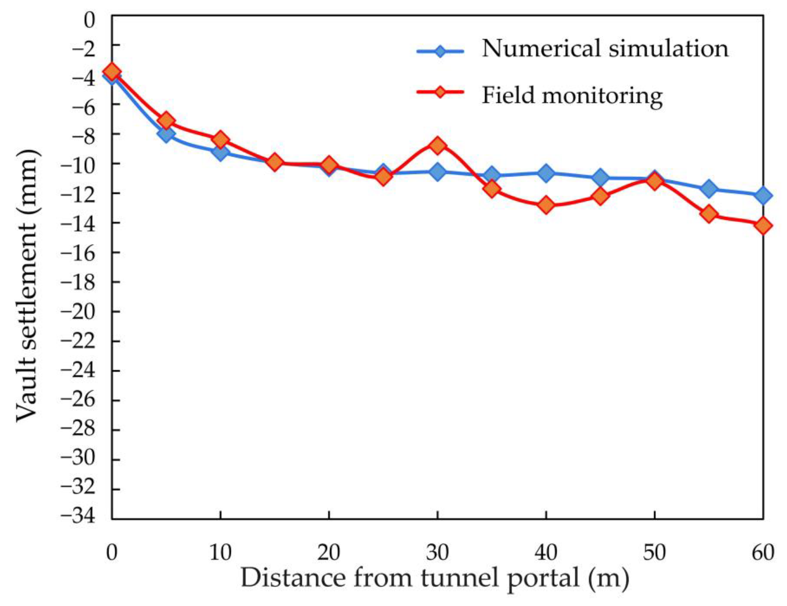
4.1. Numerical Model Verification

In order to verify the accuracy of the numerical calculation model, the vertical final settlement of the vault of the right tunnel at different distances from the portal after the tunnel excavation in the numerical calculation and field monitoring was compared and analyzed, as shown in Figure 6. It can be seen from the figure that the curves of simulation results and monitoring results are similar in shape and size. The farther away from the portal, the greater the vertical deformation of the vault. The field monitoring value fluctuates on both sides of the simulation value. The maximum error between the simulation value and the monitoring value is 2.13 mm, the minimum error is 0.03 mm, and the average error is 1.03 mm. It can be seen that the numerical model has high accuracy.

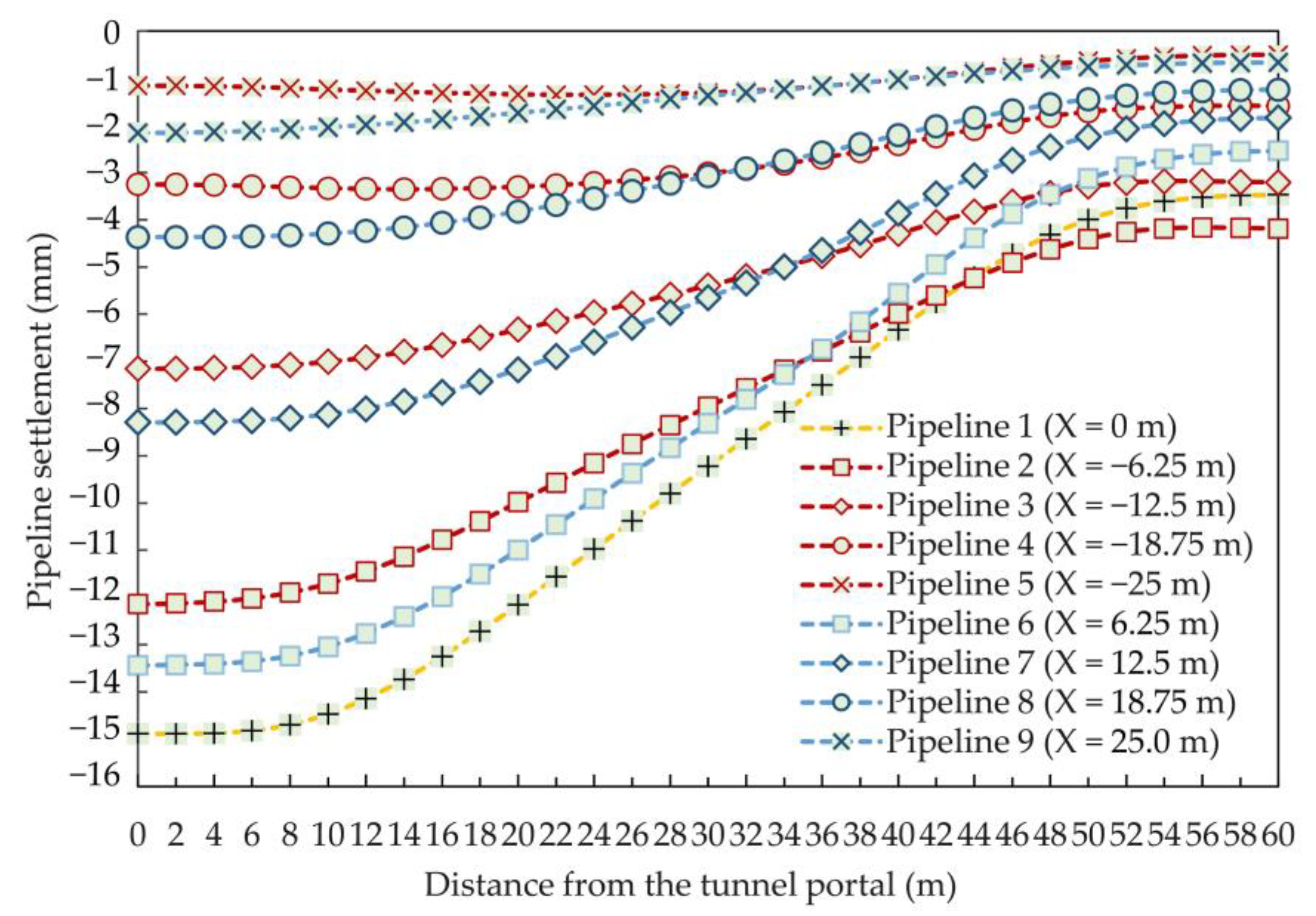
4.2. Influence of the Relative Position between Pipeline and Tunnel

4.2.1. Pipeline Horizontal Distance

Figure 7 shows the vertical deformation curve of the top of the pipeline at different horizontal positions. The abscissa in the figure was the Y coordinate corresponding to the monitoring point on the pipeline in the model, that was, the distance from the tunnel portal. There were 9 pipelines arranged between X = −25 m and X = 25 m. The relative positions and numbering of pipelines are shown in Figure 5a. Figure 7 indicates that except for several monitoring points at the tunnel tail, the settlement of pipeline 1 at other locations was generally greater than that of other pipelines, indicating that the pipeline deformation above the central axis of the double-arch tunnel, that is, the central axis of the central pilot tunnel, was most affected by the tunnel excavation. On the basis of the analysis of the changing trend of a curve, it was found that the settlement of the pipeline at the portal section was greater than that at the middle part of the tunnel, and greater than that at the tail part of the tunnel. This is because the support structure was not perfect during the excavation of the portal section, and the surrounding strata had a large displacement after the release of surrounding rock stress. With the continuous progress of the excavation and support process, when the excavation surface advanced to the middle part of the tunnel and the tail part of the tunnel, the primary lining, secondary lining and invert arch and other supporting structures had been relatively perfect, so the settlement of underground pipeline was worth controlling to a certain extent. It also can be seen the settlement of the pipeline converged at the end of the tunnel. The analysis believed that the end excavation of the tunnel has been completed, and there was no subsequent excavation to disturb the surrounding rock, so the pipeline settlement here was small.
To more intuitively reflect the influence of pipeline horizontal distance changes on pipeline deformation, the maximum settlement of the pipeline at different positions was taken out and plotted, as shown in Figure 8. The maximum vertical deformation of the pipeline above the central axis of the double-arch tunnel was significantly higher than that of the pipeline at other positions. When the distance between the underground pipeline and the central axis of the tunnel gradually increased, the maximum settlement value of the pipeline kept decreasing.

4.2.2. Pipeline Horizontal Distance

Figure 9a–c successively show the cloud diagram of vertical deformation, horizontal deformation, stress and axial force of the pipeline when the pipeline buried depth was set to h = 1.5 m, h = 2.0 m and h = 2.5 m. In the three conditions, the maximum vertical deformation of the pipeline was 16.0, 16.5, and 17.3 mm, the maximum horizontal deformation of the pipeline was 4.73, 4.28, and 4.14 mm, the maximum stress of the pipeline was 1.09, 1.18, and 1.11 MPa, and the maximum axial force of the pipeline was 52.4, 54.0, and 54.8 kN. Both vertical maximum deformation and axial force of pipeline increased with the increase of buried depth. With the increase of the pipeline buried depth, the maximum horizontal deformation of the pipeline decreased slightly, and the change of the pipeline stress was not obvious.
To clearly analyze the influence of the buried depth of the pipeline on the settlement of the pipeline, the settlement value of the top of pipeline 1 above the central axis of the tunnel was drawn, as shown in Figure 10. It can be seen from the vertical deformation of the pipeline under different buried depths that the settlement of the pipeline at the portal section was greater than that at the middle of the tunnel, and greater than that at the tunnel tail. Under the same conditions of other factors, the pipeline settlement caused by tunnel excavation increased with the increasing buried depth. The vertical deformation of the pipeline with the buried depth of 2.5 m increased by 1.45 mm at most compared with the pipeline with the buried depth of 1.5 m. The buried pipelines of the project were within 2.5 m below the ground. Therefore, special attention should be paid to the deformation of pipelines with large buried depth, that was, pipelines close to the tunnel.

4.3. Influence Analysis of Pipeline Parameters

4.3.1. Pipeline Diameter

Figure 11a–c successively show the cloud diagram of vertical deformation, horizontal deformation, stress and axial force of the pipeline when the pipeline diameter was set to d = 400 mm, d = 600 mm and d = 1000 mm. The maximum vertical deformation under three conditions were 17.5, 17.3, and 14.8 mm, respectively, the maximum horizontal deformation was 4.13, 4.14, and 3.66 mm, respectively, the maximum stress was 0.98, 1.11, and 1.41 MPa, respectively. The maximum axial force was 48.7, 54.8, and 70.1 kN, respectively. The maximum stress and axial force of the pipeline increased with the increase of pipeline diameter. With the increase of pipeline diameter, the maximum vertical deformation caused by tunnel excavation decreased, while the maximum horizontal deformation decreased slightly. The distribution of pipeline deformation, stress and axial force were basically unchanged.
Take the settlement of the top of pipeline 1 above the central axis of the tunnel to analyze the influence of pipeline diameter on pipeline settlement, as shown in Figure 12. Under the same other factors, the larger the pipeline diameter, the smaller the pipeline settlement caused by tunnel excavation. The vertical deformation of the pipeline with a diameter of 400 mm increased by 2.97 mm at most compared with that of the pipeline with a diameter of 1000 mm. The pipeline diameter of the project varied from 400 mm to 1000 mm, the diameter of sewage pipe was 400 mm, the diameter of gas pipe and rainwater pipe was 500 mm, and the diameter of water supply pipe was 600 mm. Therefore, the monitoring of the deformation of small diameter pipelines and the stress change of large diameter pipelines should be strengthened to prevent the deformation of small diameter pipelines from exceeding the standard value and the stress of large diameter pipelines from exceeding the allowable stress.

4.3.2. Pipeline Wall Thickness

Figure 13a–c show the vertical deformation, horizontal deformation, stress and axial force of the pipeline when the pipeline wall thickness was set to n = 50 mm, n = 75 mm and n = 100 mm. In the three working conditions, the maximum vertical deformation of the pipeline was 17.3, 17.7, and 20.0 mm, the maximum horizontal deformation of the pipeline was 4.14, 4.25, and 4.76 mm, the maximum stress of the pipeline was 1.11, 0.94, and 0.86 MPa, and the maximum axial force of the pipeline was 54.8, 69.6, and 85.0 kN. The vertical deformation, horizontal deformation and maximum axial force of the pipeline increased with the increase of pipeline wall thickness. With the increase of pipeline wall thickness, the maximum stress of pipeline caused by tunnel excavation decreased gradually. The distribution of pipeline deformation, stress and axial force were basically unchanged.
The settlement of the top of pipeline 1 above the central axis of the tunnel is shown in Figure 14. Under the same conditions of other factors, the greater the pipeline wall thickness, the greater the settlement of the pipeline caused by tunnel excavation. The vertical deformation of the pipeline with a wall thickness of 100 mm increased by 3.07 mm at most compared with that of the pipeline with a wall thickness of 50 mm. With the increase of pipeline wall thickness, the self-weight of the pipeline increases. After the excavation of double-arch tunnel, there was an unloading surface under the pipeline. Due to the self-weight, the pipeline deformed along with the excavation, and the settlement of thick pipeline with large self-weight was greater than that of thin pipeline with small self-weight. Therefore, more attention should be paid to the deformation of pipelines with larger wall thickness.

4.3.3. Pipeline Section Shape

Figure 15a,b show the vertical deformation, horizontal deformation, stress and axial force of the pipeline with the same cross-sectional area in square and circular, respectively. The maximum vertical deformation of pipeline under two conditions were 15.8 and 17.3 mm, the maximum horizontal deformation of pipeline were 39.2 and 41.4 mm, the maximum pipeline stress were 1.34 and 1.11 MPa, and the maximum pipeline axial force was 67.0 and 54.8 kN, respectively. When other factors were the same, the vertical and horizontal deformation of the circular pipeline caused by tunnel excavation was larger than that of the square pipeline. However, the stress and axial force of the square pipeline were greater than those of the circular pipeline. The reason was that the square pipeline had sharp corners, which was easy to cause stress concentration. The distribution of pipeline deformation, stress and axial force basically remained unchanged.
Take the settlement of the top of pipeline 1 above the central axis of the tunnel to analyze the influence of different section shapes on the settlement of the pipeline, as shown in Figure 16. When other influencing factors were the same, the vertical deformation of the circular pipeline was increased by 1.00 mm at most than the square pipeline in tunnel excavation. Therefore, in the actual construction, more attention should be paid to the deformation of the circular pipeline.

4.3.4. Pipeline Material

Figure 17a–c show the vertical deformation, horizontal deformation, stress and axial force of the pipeline when the pipeline material is iron, concrete, and PVC. The physical parameters of the pipeline material in the model are shown in Table 3.
Figure 17 indicates that the maximum vertical deformation of pipeline under three working conditions were 15.2, 17.3, and 17.7 mm, the maximum horizontal deformation of the pipeline was 3.73, 4.14, and 4.38 mm, and the maximum pipeline stress was 1.11, 83.2, and 0.69 kPa, respectively, and the maximum axial force of the pipeline was 54.8, 4.15, and 0.034 kN, respectively. The vertical deformation and horizontal deformation of PVC pipe were the largest, and the vertical deformation and horizontal deformation of iron pipe were small, but the stress and internal force value of iron pipe was large. Generally speaking, the greater the stiffness of the pipeline, the stronger the ability to resist deformation and the smaller the deformation. However, the stress and internal force of the pipeline were large, which may lead to brittle failure when reaching the stress limit state. The smaller the stiffness of the pipeline, the stronger the ability to coordinate deformation with the surrounding rock and soil mass. Therefore, the settlement of the flexible pipeline was greater, and the pipeline would be damaged when the deformation reached the limit.
The settlement of the top of pipeline 1 above the central axis of the tunnel is shown in Figure 18. The maximum settlement of PVC pipe was 15.78 mm, the maximum settlement of concrete pipe was 14.89 mm, and the maximum settlement of iron pipe was 13.17 mm. Therefore, more attention should be paid to the settlement of PVC pipeline caused by tunnel excavation, the stress and internal force of iron pipe in the aviation process, and the segment cracking caused by settlement deformation of concrete pipe.

4.4. Influence Analysis of Tunnel Construction Parameters

Figure 19a–c show the cloud diagrams of vertical deformation, horizontal deformation, stress and axial force of the pipeline during full-section excavation, three-step reserved core soil excavation, and three-step excavation. Under the three working conditions, the maximum vertical deformation of the pipeline was 46.3, 31.7, and 17.3 mm, the maximum horizontal deformation of the pipeline was 14.6, 4.14, and 8.79 mm, the maximum stress of the pipeline was 1.53, 1.11, and 1.18 MPa, and the maximum axial force of the pipeline was 63.9, 54.8, and 52.0 kN. As the full-section excavation had the greatest disturbance to the surrounding rock of the tunnel, the vertical and horizontal deformation of the pipeline were large, followed by the three-step excavation, and the vertical and horizontal deformation of the pipeline caused by the excavation of the reserved core soil of the three-step was the smallest. The variation trend of pipeline stress and axial force was the same as that of deformation, but the variation amplitude was small. Therefore, from the perspective of controlling the deformation of the surrounding pipelines and ensuring construction safety, the three-step reserved core soil method should be selected as the construction method for the double-arch tunnel.
The settlement of the top of pipeline 1 above the central axis of the tunnel is shown in Figure 20. Under the same other factors, the settlement caused by full-section excavation at each position of the pipeline was significantly greater than the other two excavation methods, and the pipeline settlement caused by the three-step reserved core soil excavation was the smallest. The maximum settlement caused by full section excavation was 36.57 mm, the maximum settlement caused by three-step excavation was 27.15 mm, and the maximum settlement caused by three-step reserved core soil excavation was 14.89 mm. Compared with the other two construction methods, the three-step reserved core soil method can effectively control the stress and deformation of the underground pipeline.

5. Conclusions

Based on the double-arch tunnel part of Haicang tunnel in Xiamen, the deformation and stress laws of underground pipelines in different horizontal distances, buried depth, diameter, wall thickness, shape, material and excavation methods were studied by using numerical analysis, and the following conclusions are drawn:
(1)
The underground pipelines near the central axis of the double-arch tunnel deformed most obviously. Therefore, special attention should be paid to the protection of the underground pipelines above the central axis of the tunnel. The pipeline should be relocated or protected before tunnel excavation.
(2)
The circular underground pipelines with large buried depth, small diameter and large wall thickness were greatly affected by tunnel excavation, so protection measures should be strengthened during tunnel excavation.
(3)
Larger diameter and distance between the pipeline and tunnel, smaller pipeline wall thickness or square rigid pipeline resulted in smaller pipeline deformation.
(4)
Three-step reserved core soil excavation method reduced pipeline deformation compared with the other excavation methods which is advantages pipeline protection.
(5)
The relative position of pipeline and tunnel, and construction method had a great influence on pipeline deformation. Pipeline type, pipeline material, pipeline diameter and excavation method had a great influence on pipeline stress.
The influence of several main factors on the response of adjacent underground pipelines during double-arch tunnel excavation had been discussed here with a special case. In future, further studies on a common double-arch tunnel soil type, blast damage, hydrological condition and supporting time should also be considered under certain conditions.

Author Contributions

J.W., Z.W. and A.C. carried out the main research task and wrote the manuscript. J.W. proposed the original idea and contributed to the revision of the obtained results and the whole manuscript. Z.S., X.L. (Xiao Lin) and L.S. performed utilization on-site. X.L. (Xiaotian Liu), H.L. and Y.S. performed investigation. All authors have read and agreed to the published version of the manuscript.

Funding

This research was funded by the Shanghai Municipal Science and Technology Project (18DZ1201301; 19DZ1200900); Xiamen Road and Bridge Group (XM2017-TZ0151; XM2017-TZ0117); the project of Key Laboratory of Impact and Safety Engineering (Ningbo University), Ministry of Education (CJ202101); Shanghai Municipal Science and Technology Major Project (2021SHZDZX0100) and the Fundamental Research Funds for the Central Universities; Key Laboratory of Land Subsidence Monitoring and Prevention, Ministry of Natural Resources of the People’s Republic of China (No. KLLSMP202101); Suzhou Rail Transit Line 1 Co. Ltd. (SURT01YJ1S10002); China Railway 15 Bureau Group Co. Ltd.( CR15CG-XLDYH7-2019-GC01); the National Natural Science Foundation of China (Grant No. 41907230).

Data Availability Statement

The data presented in this study are available on request from the corresponding author.

Conflicts of Interest

The authors declare no conflict of interest.

References

  1. Xu, Z.S.; Wang, B.L.; Kong, J.; Chen, T.; Liang, Y. Study on the influence of ceiling tunnel angle on the gas shunting efficiency of urban highway tunnel. Case Stud. Therm. 2021, 25, 100888. [Google Scholar] [CrossRef]
  2. Yang, H.; Liu, C.; Jiang, X.; Shi, H.; Sun, G. Shaking table test and numerical simulation for dynamic response of shallow-buried bias double-arch tunnel. Geotech. Geolog. Eng. 2020, 38, 3915–3929. [Google Scholar] [CrossRef]
  3. Vosoughifar, H.; Madadi, F.; Rabiefar, A. Modified dynamic stress concentration factor for twin tunnels using a novel approach of FEM-scattering. Tunn. Undergr. Sp. Tech. 2017, 70, 30–41. [Google Scholar] [CrossRef]
  4. Wang, S.R.; Wang, Y.G.; Li, C.L.; Zou, Z.S.; Cui, F. Evolution characteristics analysis of pressure—Arch of a highway tunnel under different stress conditions. JESTEC 2016, 9, 99–105. [Google Scholar] [CrossRef]
  5. Wang, H.N.; Zeng, G.S.; Sutilt, S.; Jiang, M.G.; Wu, L. Analytical solutions of stresses and displacements for deeply buried twin tunnels in viscoelastic rock. Int. J. Rock Meck. Min. 2017, 93, 13–29. [Google Scholar] [CrossRef]
  6. Zhu, Y.T.; Zhang, H.; Zhang, Z.X.; Huang, X.; Liu, K. Physical model test study of influence of advance of shield tunnel on adjacent underground pipelines. Rock Soil Mech. 2016, 37, 151–160. [Google Scholar] [CrossRef]
  7. Wang, H.T.; Wu, Y.D.; Jin, H.; Jia, J.Q.; Wang, K. Field measurement and numerical simulation of the influence of blasting excavation on adjacent buried pipelines. Int. J. Crit. Infr. 2019, 15, 70–89. [Google Scholar] [CrossRef]
  8. Attewell, P.B.; Yeates, J.; Selby, A.R. Soil Movements Induced by Tunnelling and Their Effects on Pipelines and Structures; Blackie and Son Ltd.: London, UK, 1986. [Google Scholar]
  9. Klar, A.; Vorster, T.E.B.; Soga, K.; Mair, R.J. Soil-pipe interaction due to tunneling: Comparison between Winkler and elastic continuum solutions. Geotechnique 2005, 55, 461–466. [Google Scholar] [CrossRef]
  10. Vorster, T.E.B.; Klar, A.; Soga, K.; Mair, R.J. Estimating the effects of tunneling on existing pipelines. J. Geotech. Geoen. 2005, 131, 1399–1410. [Google Scholar] [CrossRef]
  11. Yoo, C.S.; Kimj, H. A web-based tunneling -induced building/utility damage assessment system TURISK. Tunn. Undergr. Space Technol. 2003, 18, 497–511. [Google Scholar] [CrossRef]
  12. Yoo, C.S. Damage assessment of buried pipelines due to tunnelinginduced ground movements. J. Korean Geotech. Soc. 2001, 17, 71–86. [Google Scholar]
  13. Molnar, K.M.; Finno, R.J.; Rossow, E.C. Analysis of Effects of Deep Beaced Excavations on Adjacent Buried Utilities; Northwesten University: Evanston, IL, USA, 2003. [Google Scholar]
  14. Hunter, A. Effect of trenchless technologies on existing iron pipelines. Proc. Inst. Civ. Eng. Geotech. Eng. 2005, 158, 159–167. [Google Scholar] [CrossRef]
  15. Ukritchon, B.; Keawsawasvong, S. Undrained stability of unlined square tunnels in clays with linearly increasing anisotropic shear strength. Geotech. Geolog. Eng. 2020, 38, 897–915. [Google Scholar] [CrossRef]
  16. Keawsawasvong, S.; Ukritchon, B. Design equation for stability of shallow unlined circular tunnels in Hoek-Brown rock masses. Bull. Eng. Geol. Environ. 2020, 79, 4167–4190. [Google Scholar] [CrossRef]
  17. Liu, L.J.; Zhang, L.Y.; Lan, J.X.; Wang, M.L. Study on the Effect of Shield Tunnel Construction on Underground Pipeline Deformation by Experiment and Monitoring. Adv. Mater. Res. 2011, 413, 289–294. [Google Scholar] [CrossRef]
  18. Wham, B.P.; Argyrou, C.; O’Rourke, T. Jointed pipeline response to tunneling-induced ground deformation. Can. Geotech. J. 2016, 53, 1794–1806. [Google Scholar] [CrossRef]
  19. Wei, G.; Wang, C.; Cai, S.Q.; Xu, X.; Hong, Z.H.; Cui, C.H.; Xu, Y.F. Model test study on influence of quasi-rectangular shield construction on underground pipelines. Chin. J. Geotech. Eng. 2019, 5, 1–6. [Google Scholar] [CrossRef]
  20. Shi, J.W.; Wang, Y.N.; Ng, C.W.W. Three-dimensional centrifuge modeling of ground and pipeline response to tunnel excavation. J. Geotech. Geoen. 2016, 142, 04016054. [Google Scholar] [CrossRef]
  21. Marshall, A.M.; Klar, A.; Mair, R.J. Tunneling beneath buried pipes: View of soil strain and its effect on pipeline behavior. J. Geotech. Geoen. 2010, 136, 1664672. [Google Scholar] [CrossRef]
  22. Kimura, T.; Kusakabe, O.; Saitoh, K. Geotechnical model tests of bearing capacity problems in a centrifuge. Geotechnique 1985, 35, 33–45. [Google Scholar] [CrossRef]
  23. Zhang, C.; Yu, J.; Huang, M. Effects of tunnelling on existing pipelines in layered soils. Comput. Geotech. 2012, 43, 12–25. [Google Scholar] [CrossRef]
  24. Liu, J.L.; Liu, J.Q. Influence of tunnel excavation on adjacent underground pipeline. Adv. Mater. Res. 2010, 150–151, 1777–1781. [Google Scholar] [CrossRef]
  25. Yang, R.L.; Zhang, T.Y. Study on influence of tunnel excavation on seismic performance of underground pipeline. App. Mech. Mater. 2011, 1801–1806. [Google Scholar] [CrossRef]
  26. Guo, D.L.; Zhao, D.S. Analysis of effects of a double-tube parallel tunnel excavation on underground pipelines. App. Mech. Mater. 2013, 395–396, 477–480. [Google Scholar] [CrossRef]
  27. Wang, Y.; Kong, L.W.; Wang, Y.L.; Li, X.W. Analysis of influence of shield tunneling on overlying underground pipelines based on HSS model. IOP Conf. Ser. Mater. Sci. Eng. 2018, 423, 012017. [Google Scholar] [CrossRef]
  28. Yu, Y.; Chen, N. Effect on municipal pipeline under subway tunnel excavation in drill-blasting. In AIP Conference Proceedings, Tianjin City, China, 9–10 June 2018; Xiao, J., Ke, J., You, Z., Eds.; AIP Publishing: Melville, NY, USA, 2018; Volume 1995, p. 020033. [Google Scholar] [CrossRef]
  29. Yang, R.L.; Kong, J.; Zhou, J.H. Study on influencing factors of tunnel in seismic performance of adjacent underground pipeline. Adv. Mater. Res. 2013, 807–809, 1823–1828. [Google Scholar] [CrossRef]
  30. Kumar, B.; Sahoo, J.P. Support pressure for circular tunnels in two layered undrained clay. J. Rock Mech. Geotech. Eng. 2020, 12, 135–148. [Google Scholar] [CrossRef]
  31. Kumar, B.; Sahoo, J.P. Stability of unsupported circular tunnels in anisotropic normally and over consolidated saturated clay. Comput. Geotech. 2021, 135, 104148. [Google Scholar] [CrossRef]
  32. Sahoo, J.P.; Kumar, B. Peripheral stability of circular tunnels in anisotropic undrained clay. Tunn. Undergr. Sp. Tech. 2021, 114, 103898. [Google Scholar] [CrossRef]
  33. Ding, W.Q.; Wang, X.X.; Li, Z.G.; Wang, J.X.; Chu, X.D. Optimal analysis of construction schemes for shallow large span longshan twin tunnel. Chin. J. Rock Mechan. Eng. 2005, 22, 4042–4047. [Google Scholar] [CrossRef]
  34. Peck, R.B. Deep excavations and tunnelling in soft ground. Proc. 7th ICSMFE 1969, 1969, 225–290. [Google Scholar]
  35. Wu, F.B.; Jin, H.; Shang, Y.J. Underground pipeline deformation prediction around urban rail transit tunnel engineering. Chin. J. Rock Mech. Eng. 2013, 32, 3592–3601. [Google Scholar]
  36. Yang, C.Z.; Wu, Y.J.; Wang, W.; Tang, Y.Q. Analysis on influence of spacial effect on excavation of soft rock tunnel with large cross section. Chin. J. Undergr. Sp. Eng. 2021, 17, 511–519. [Google Scholar]
  37. Yu, Y.; Damians, I.P.; Bathurst, R.J. Influence of choice of FLAC and PLAXIS interface models on reinforced soil–structure interactions. Comput. Geotech. 2015, 65, 164–174. [Google Scholar] [CrossRef]
  38. Wu, S.Y.; Wen, B.P. Analysis of a numerical simulation on the deformation of inlaid pipeline in the mining-over areas. J. Saf. Environ. 2014, 14, 87–91. [Google Scholar] [CrossRef]
Figure 1. Underground pipelines around the excavation area of Haicang tunnel.
Applsci 12 00621 g001
Figure 2. Distribution of underground pipelines in tunnel address area.
Applsci 12 00621 g002
Figure 3. Construction procedure of three pilot tunnel method.
Applsci 12 00621 g003
Figure 4. Numerical model (unit: m).
Applsci 12 00621 g004
Figure 5. Buried pipeline: (a) Oblique drawing; (b) Side view.
Applsci 12 00621 g005
Figure 6. Vertical settlement of the vault of the right tunnel.
Applsci 12 00621 g006
Figure 7. Vertical deformation of pipelines at different horizontal positions.
Applsci 12 00621 g007
Figure 8. Maximum vertical deformation of the pipeline at different horizontal positions.
Applsci 12 00621 g008
Figure 9. Vertical deformation, horizontal deformation, stress and axial force of pipeline with different buried depths: (a) h = 1.5 m; (b) h = 2.0 m; (c) h = 2.5 m.
Applsci 12 00621 g009aApplsci 12 00621 g009b
Figure 10. Vertical deformation of pipelines with different buried depths.
Applsci 12 00621 g010
Figure 11. Vertical deformation, horizontal deformation, stress and axial force of pipelines with different diameters: (a) d = 400 mm; (b) d = 600 mm; (c) d = 1000 mm.
Applsci 12 00621 g011aApplsci 12 00621 g011b
Figure 12. Vertical deformation of pipelines with different diameters.
Applsci 12 00621 g012
Figure 13. Vertical deformation, horizontal deformation, stress and axial force of pipeline with different wall thickness: (a) n = 50 mm; (b) n = 75 mm; (c) n = 100 mm.
Applsci 12 00621 g013aApplsci 12 00621 g013b
Figure 14. Vertical deformation of pipelines with different wall thicknesses.
Applsci 12 00621 g014
Figure 15. Vertical deformation, horizontal deformation, stress and axial force of pipeline with different section shapes: (a) Square; (b) Circular.
Applsci 12 00621 g015
Figure 16. Vertical deformation of pipeline with different section shapes.
Applsci 12 00621 g016
Figure 17. Vertical deformation, horizontal deformation, stress and axial force of pipeline with different pipeline materials: (a) Iron; (b) Concrete; (c) PVC.
Applsci 12 00621 g017aApplsci 12 00621 g017b
Figure 18. Vertical deformation of pipeline with different pipeline materials.
Applsci 12 00621 g018
Figure 19. Vertical deformation, horizontal deformation, stress and axial force of pipeline with different excavation methods: (a) Full-section excavation; (b) Three-step reserved core soil excavation; (c) Three-step excavation.
Applsci 12 00621 g019aApplsci 12 00621 g019b
Figure 20. Vertical deformation of pipeline with different excavation methods.
Applsci 12 00621 g020
Table 1. Model material parameters.
MaterialDensity (kg/m3)Elastic Modulus (MPa)Poisson’s RatioFrictional Angle (°)Cohesive Force (kPa)Coefficient of
Permeability
(10−6 m·s)
Thickness (m)
Miscellaneous fill190010.760.3219.426.852.524
Completely weathered granite195013.000.3520.0108.063.0022
Fragmentary strongly weathered granite230010.720.330.556.582.0024
Pipeline140020000.340.01
The pilot tunnel lining250010,500.000.250.3
Inverted arch primary support260034,000.000.150.3
Middle partition wall and side wall250030,000.000.20
Primary support of the first layer of arch260034,000.000.150.3
Primary support of the second layer of arch255032,000.000.150.22
Table 2. Influencing factors and parameter values of pipeline dynamic response.
Influencing FactorCondition 1Condition 2Condition 3
Relative position relationship between underground pipeline and tunnelPipeline buried depth (m)1.52.02.5
Pipeline diameter (mm)4006001000
Pipeline parametersPipeline wall thickness (mm)5075100
Pipeline section shapeSquareCircle-
Pipeline materialSteelConcretePVC
Tunnel construction parametersTunnel excavation methodFull section methodExcavation of reserved core soil for three stepsThree-step excavation
Table 3. Influencing factors and parameter values of pipeline dynamic response.
Pipeline MaterialsDensity (kg/m3)Elastic Modulus (GPa)Poisson’s Ratio
Iron79002000.3
Concrete2500250.2
PVC150020.35
Publisher’s Note: MDPI stays neutral with regard to jurisdictional claims in published maps and institutional affiliations.

