
Root Cause Failure Analysis of Deep-Groove Ball Bearing Used in a Governor

Abstract
:1. Introduction
2. Materials and Methods
3. Results
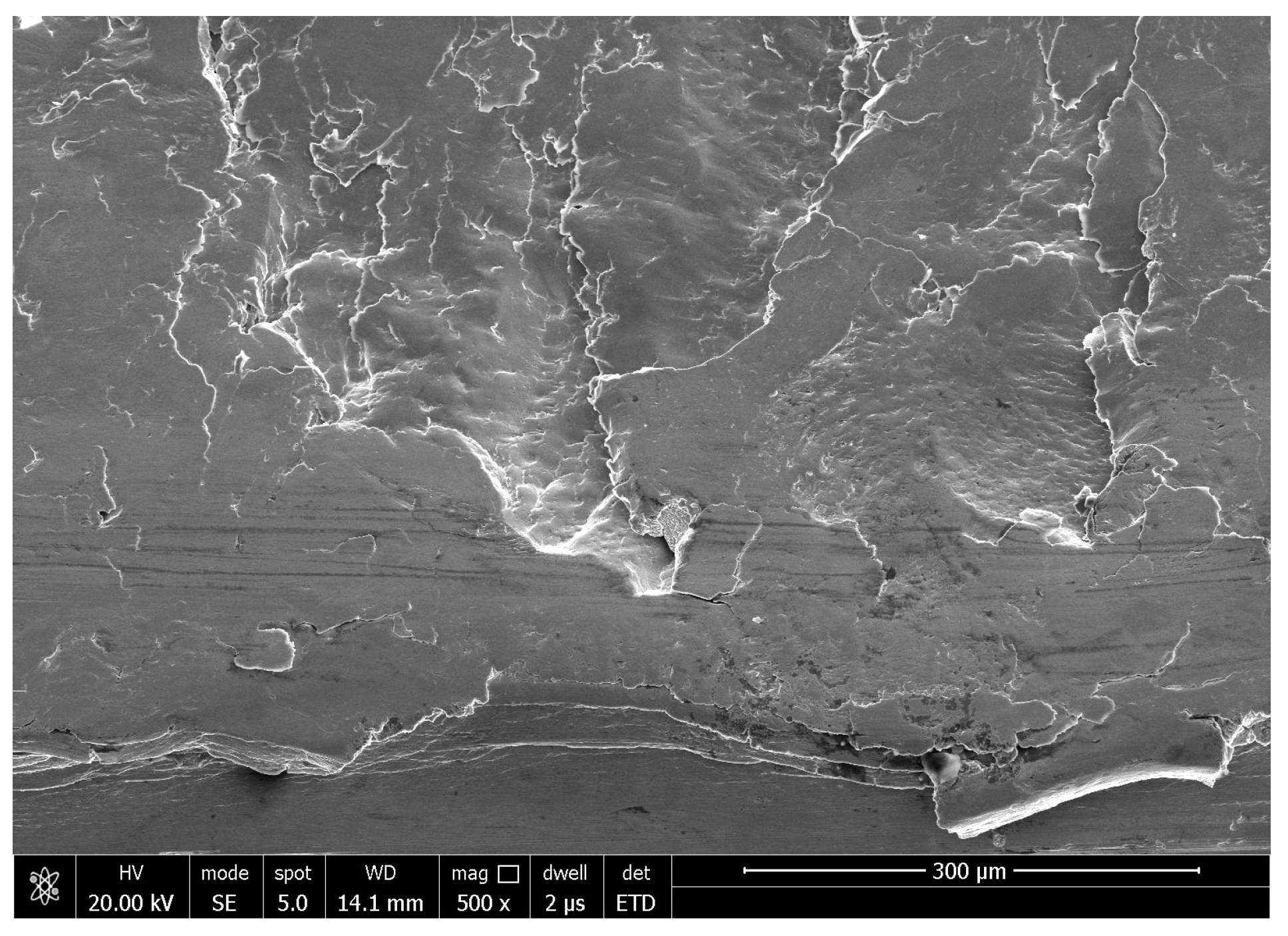
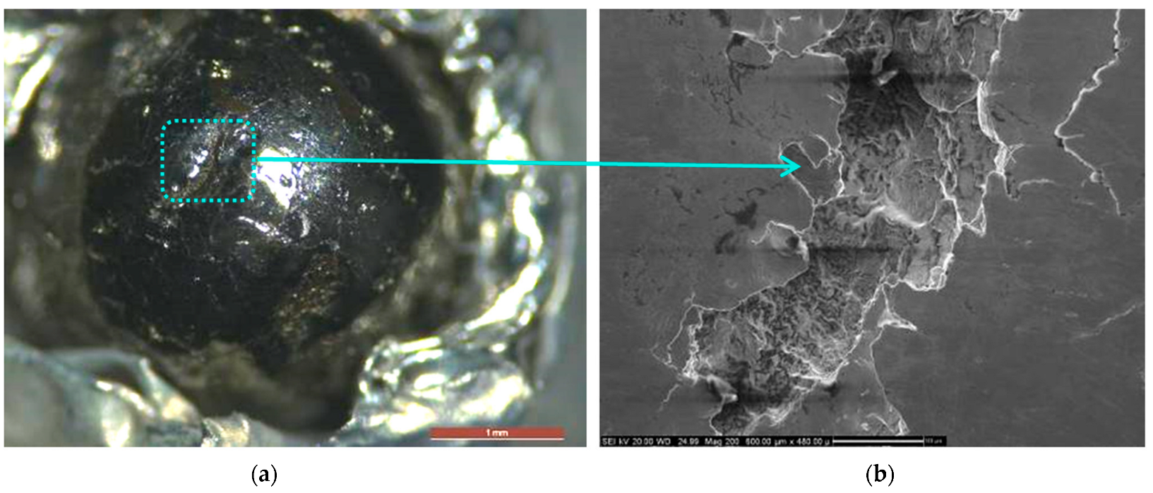
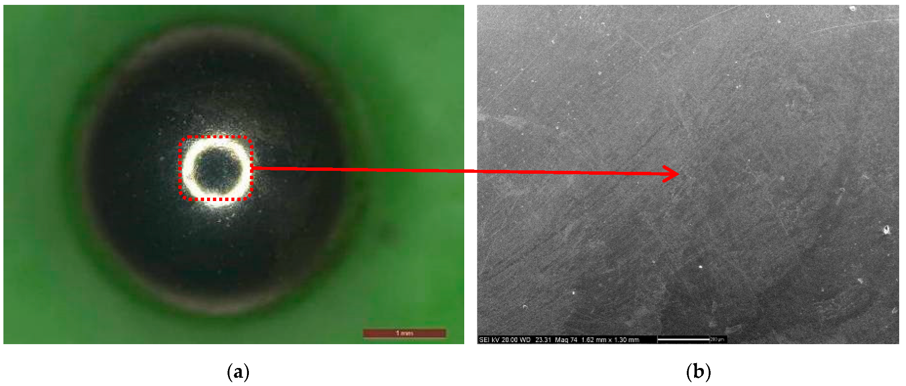
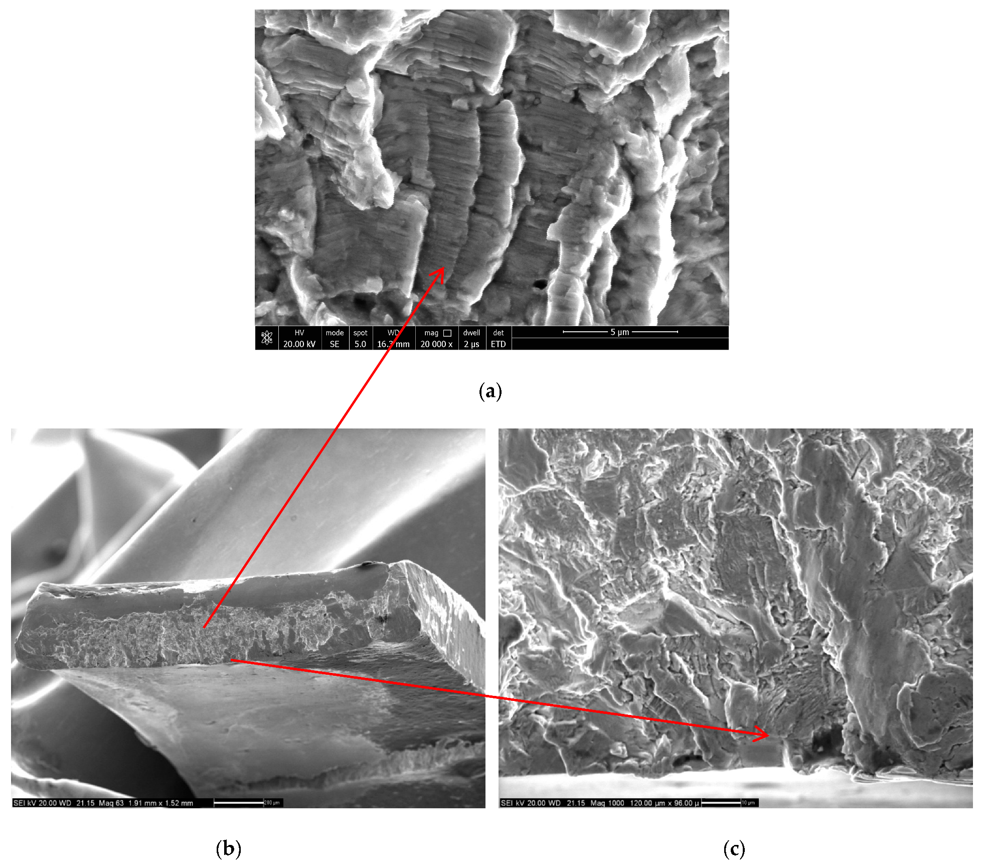
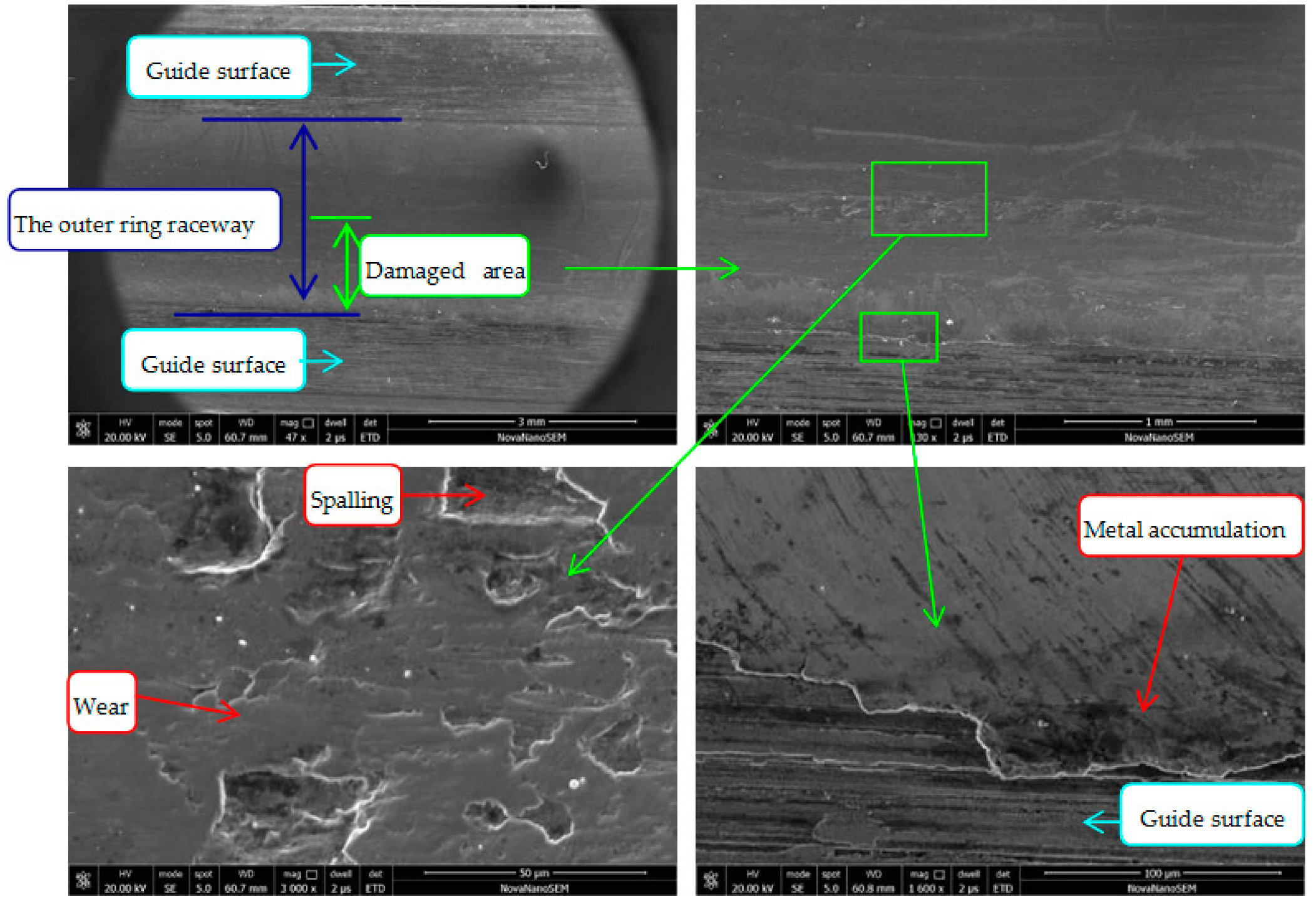
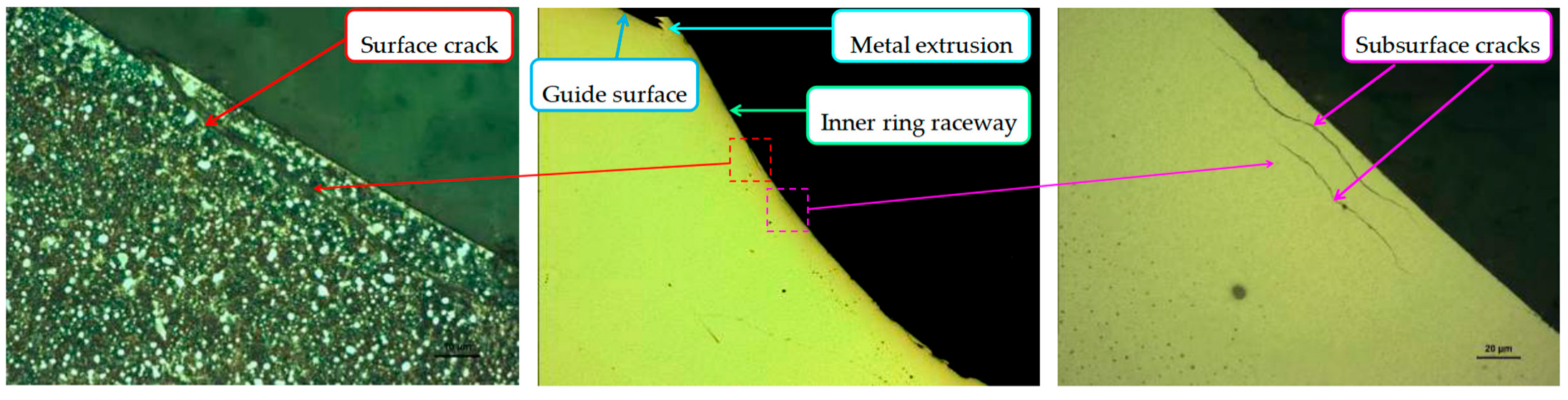
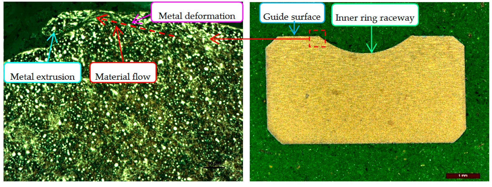
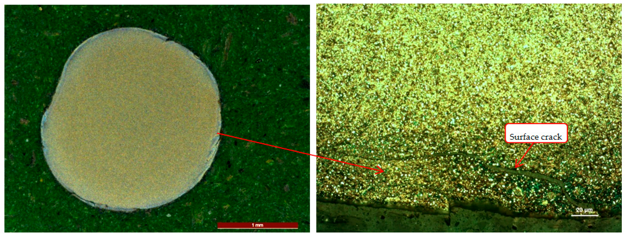
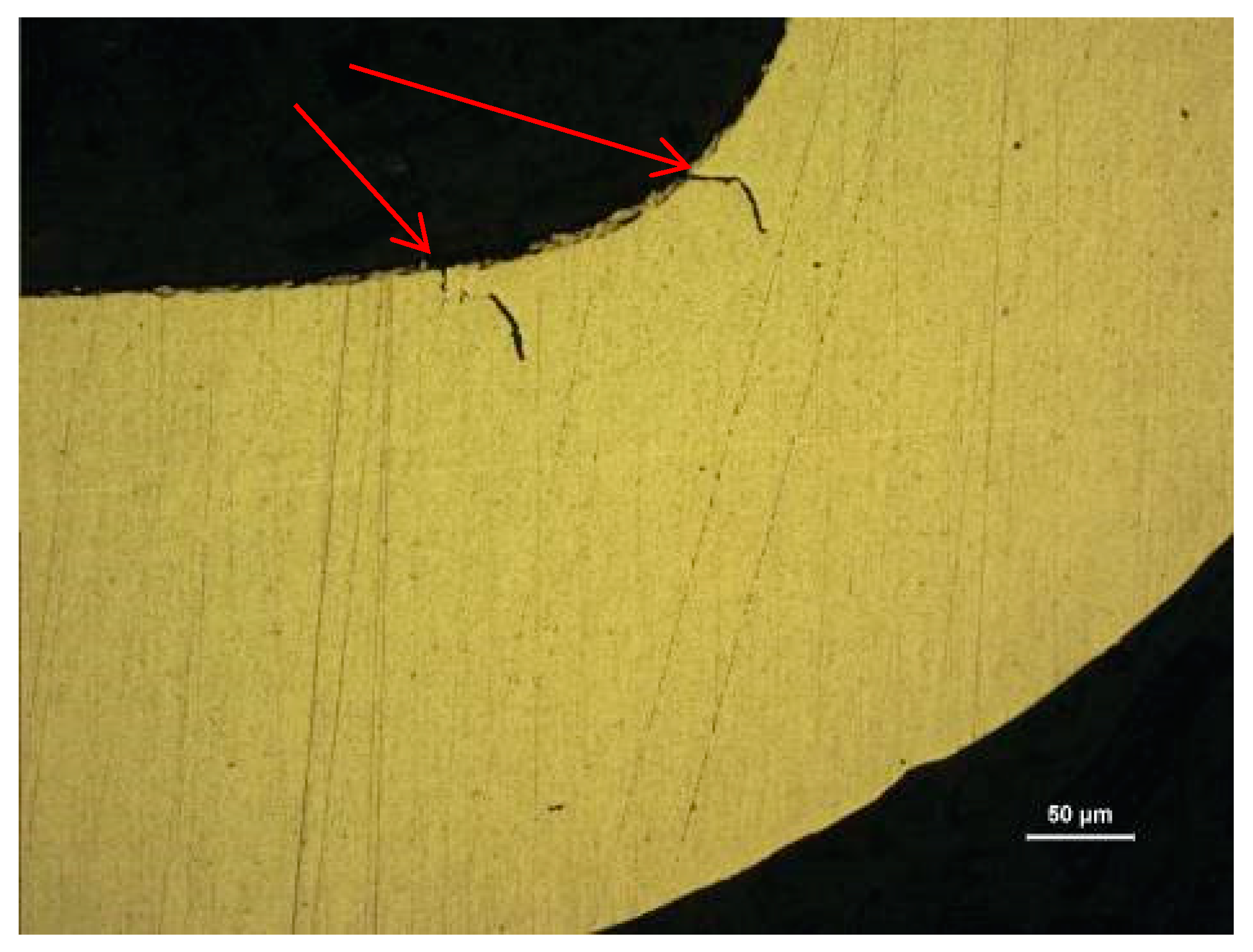
3.1. Macroscopic and Microscopic Observation
3.2. Microstructure Examination
3.3. Hardness Examination
4. Discussion
- (1)
- Failure mode and direct failure cause
- (2)
- Comprehensive analysis of the failure root cause
- (3)
- Comparative experiment
5. Conclusions
- (1)
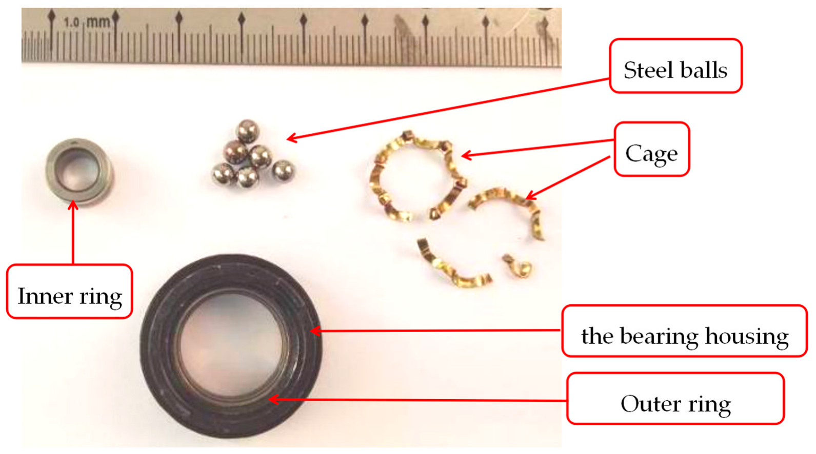
- The failure mode of the inner ring raceway and steel balls is contact fatigue spalling. The failure modes of the outer ring raceway are wear and contact fatigue spalling. The failure mode of the cage is fatigue fracture.
- (2)
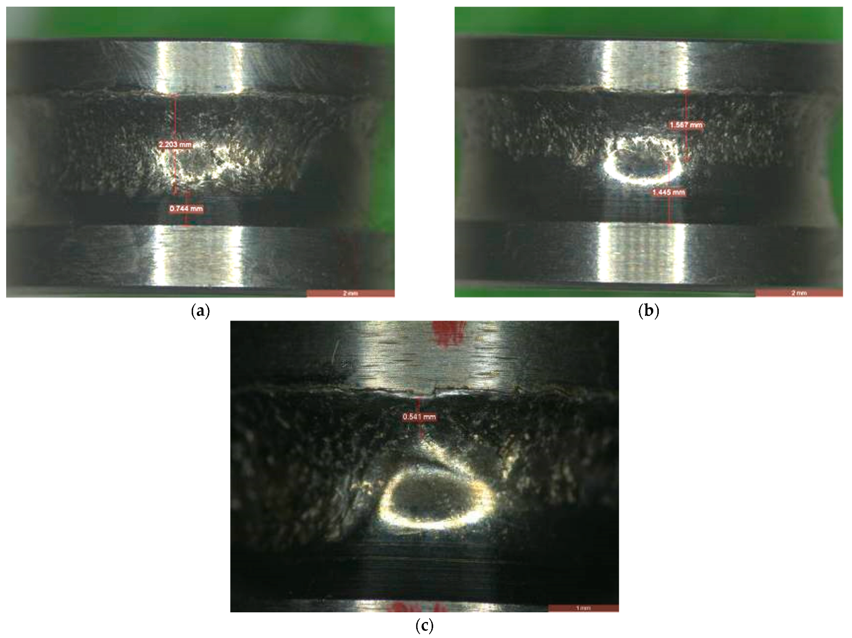
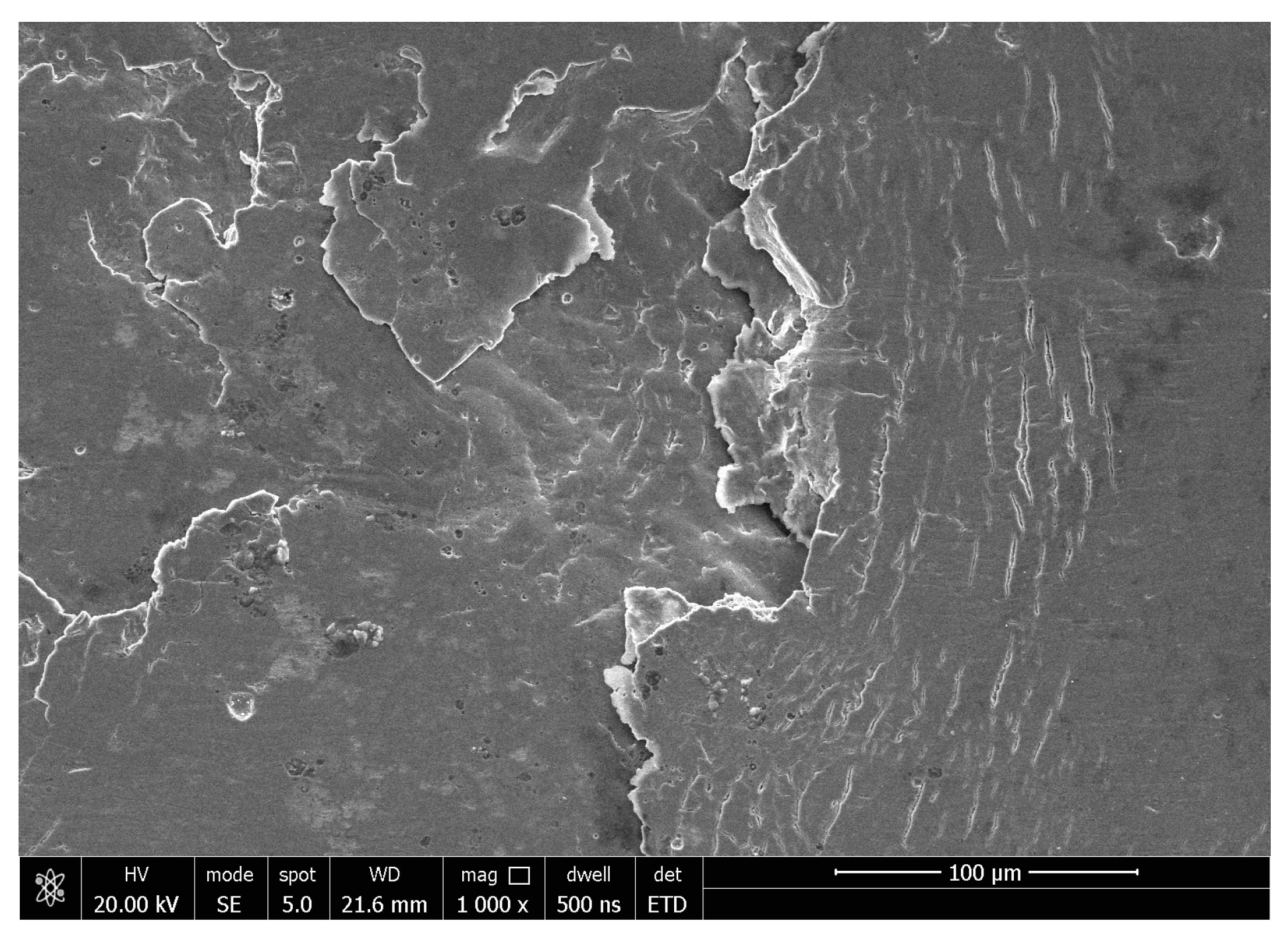
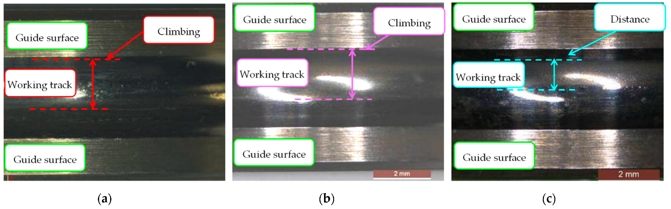
- Both the inner ring raceway and outer ring raceway exhibited the high axial load-induced damage characteristic of climbing with the morphology of metal extrusion and accumulation at the border of the raceway. The cage exhibited multiple fatigue fractures, with the characteristic of multi origins under the effect of high unbalanced axial load.
- (3)
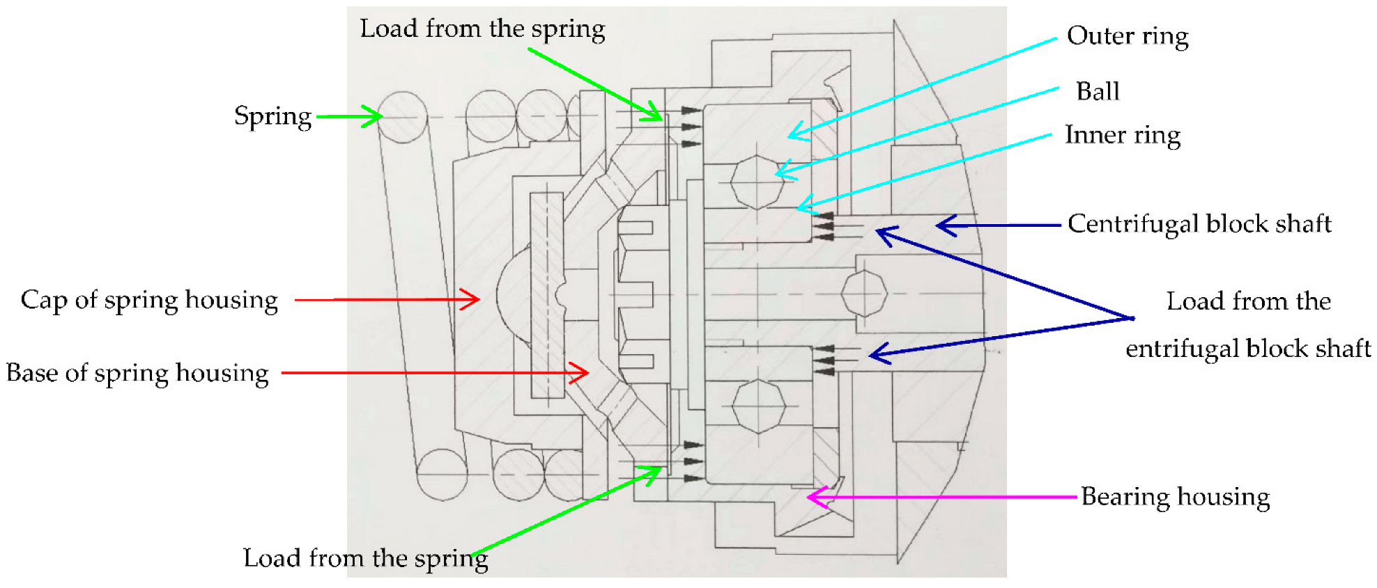
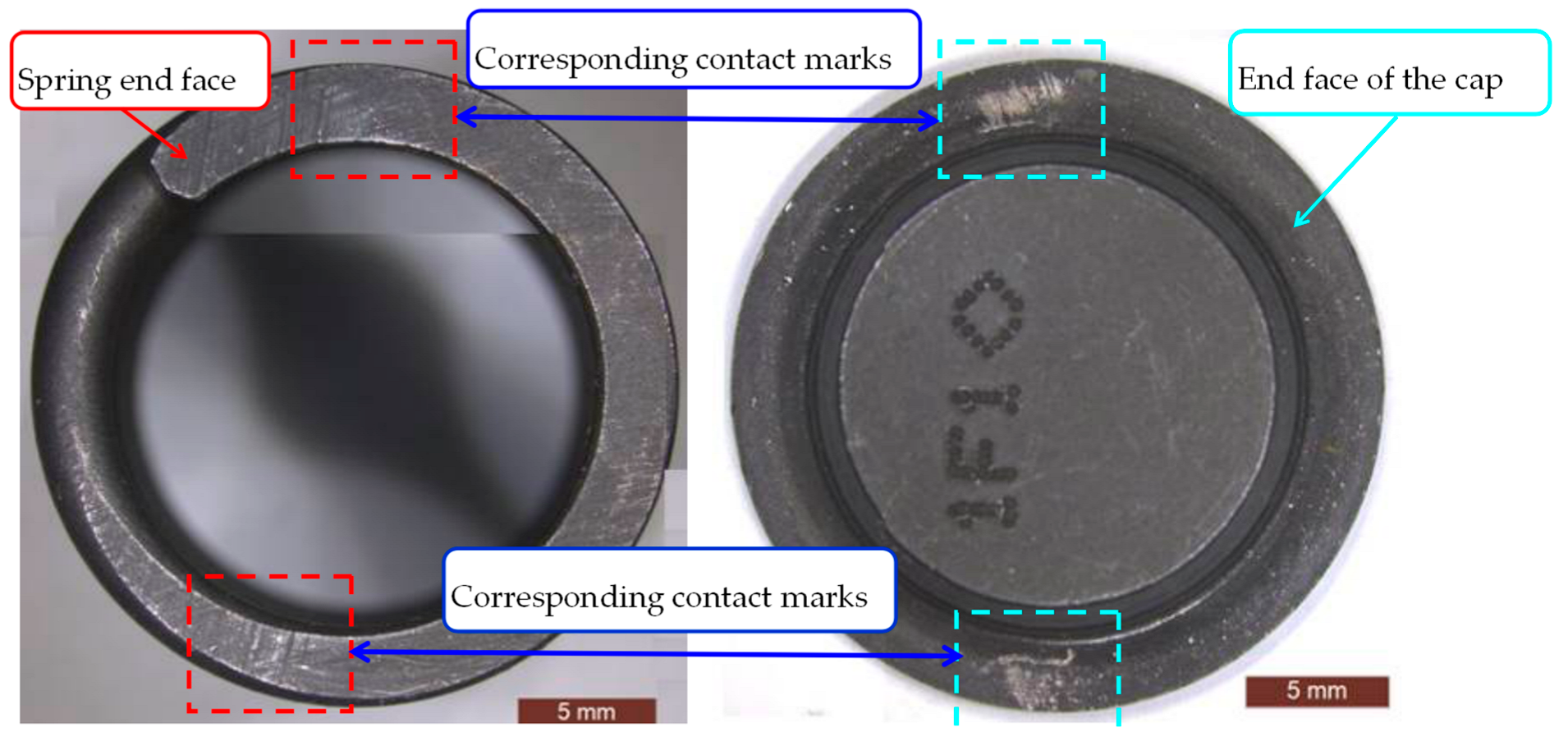
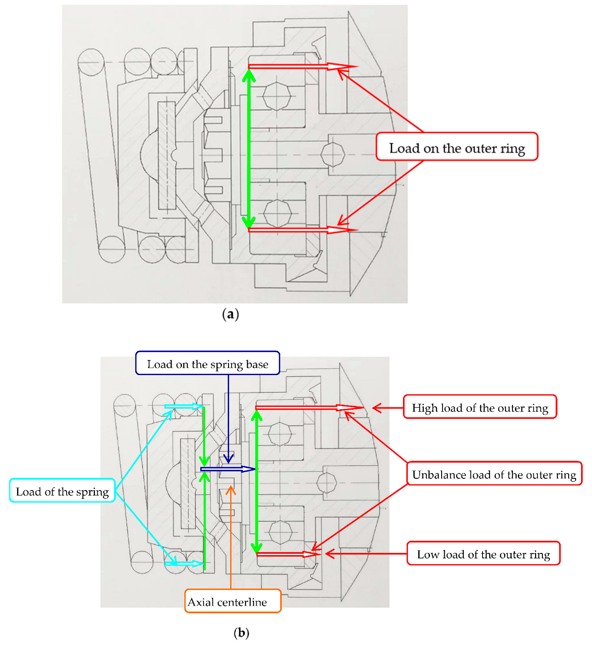
- The direct cause of the bearing failure is the high unbalanced axial load. The root cause of the bearing failure is the unqualified machining process of the spring end face. High points of the spring end face caused by the unqualified machining process induced misalignment of the outer ring and inner ring, and thereby caused the high unbalanced axial load.
- (4)
- The high points can be prevented by adopting the refined grinding process and adding detection requirements of flatness.
Author Contributions
Funding
Institutional Review Board Statement
Informed Consent Statement
Data Availability Statement
Acknowledgments
Conflicts of Interest
References
- Kudelina, K.; Baraškova, T.; Shirokova, V.; Vaimann, T.; Rassõlkin, A. Fault detecting accuracy of mechanical damages in rolling bearings. Machines 2022, 10, 86. [Google Scholar] [CrossRef]
- Hong, S.; Tong, V. Rolling-element bearing modeling: A review. Int. J. Precis. Eng. Manuf. 2016, 17, 1729–1749. [Google Scholar] [CrossRef]
- Kishore, K.; Mukhopadhyay, G. Root cause failure analysis of pinch roll bearing at Hot Strip Mill. J. Fail. Anal. Preven. 2019, 19, 219–229. [Google Scholar] [CrossRef]
- Bakoglidis, K.D.; Nedelcu, I.; Ivanov, I.G.; Meeuwenoord, R.; Schmidt, S.; Janzén, E.; Ehret, P.; Greczynski, G.; Hultman, L. Rolling performance of carbon nitride-coated bearing components in different lubrication regimes. Tribol. Int. 2017, 114, 141–151. [Google Scholar] [CrossRef]
- Alhasia, S.; Gindy, S.; Arslan, S.; Jawad, B.; Riedel, C. Analysis of failure modes of bearing outer race rotation. SAE Int. J. Passeng. Cars-Electron. Electr. Syst. 2015, 8, 240–243. [Google Scholar] [CrossRef]
- Gould, B.; Greco, A.; Stadler, K.; Vegter, E.; Xiao, X. Using advanced tomography techniques to investigate the development of White Etching Cracks in a prematurely failed field bearing. Tribol. Int. 2017, 116, 362–370. [Google Scholar] [CrossRef]
- Murugesan, V.; Sreejith, P.S.; Sundaresan, P.B.; Ramasubramanian, V. Analysis of an angular contact ball bearing failure and strategies for failure prevention. J. Fail. Anal. Prev. 2018, 18, 471–485. [Google Scholar] [CrossRef]
- Cong, F.; Chen, J.; Dong, G.; Petcht, M. Vibration model of rolling element bearings in a rotor bearing system for fault diagnosis. J. Sound Vib. 2013, 332, 2081–2097. [Google Scholar] [CrossRef]
- Salam, I.; Tauqir, A.; Haq, A.U.; Khany, A.Q. An air crash due to fatigue failure of a ball bearing. Eng. Fail. Anal. 1998, 5, 261–269. [Google Scholar] [CrossRef]
- Gloeckner, P.; Sebald, W.; Bakolas, V. An approach to understanding micro-spalling in high-speed ball bearings using a thermal elastohydrodynamic model. Tribol. Trans. 2019, 52, 534–543. [Google Scholar] [CrossRef]
- Walvekar, A.A.; Paulson, N.; Farshid, S.; Nick, W.; Martin, C. A new approach for fatigue damage modeling of subsurface-initiated spalling in large rolling contacts. J. Tribol. 2017, 139, 011101. [Google Scholar] [CrossRef]
- Yu, Z.; Yang, Z. Failure analysis of fatigue fracture on the outer ring of a cylindrical roller bearing in an air blower motor. J. Fail. Anal. Preven. 2012, 12, 427–437. [Google Scholar] [CrossRef]
- Xu, L.; Yu, Z. Failure analysis of tapered roller bearing inner rings used in heavy truck. Eng. Fail. Anal. 2020, 111, 104474. [Google Scholar] [CrossRef]
- Gagg, C.R.; Lewis, P.R. Wear as a product failure mechanism—Overview and case studies. Eng. Fail. Anal. 2007, 14, 1618–1640. [Google Scholar] [CrossRef]
- Magalhaes, J.F.; Ventsel, L.; Macdonald, D.D. Environmental effects on pitting corrosion of AISI440C ball bearing steels—experimental results. J. Soc. Tribol. Lubr. Eng. 1999, 55, 36–41. [Google Scholar]
- Prashad, H. Diagnosis of rolling-element bearings failure by localized electrical current between track surfaces of races and rolling-elements. J. Tribol. Trans. ASME 2002, 124, 468–473. [Google Scholar] [CrossRef]
- Manieri, F.; Stadler, K.; Morales-Espejel, G.E.; Kadiric, A. The origins of white etching cracks and their significance to rolling bearing failures. Int. J. Fatigue 2019, 120, 107–133. [Google Scholar] [CrossRef]
- Errichello, R.; Budny, R.; Eckert, R. Investigations of bearing failures associated with White Etching Areas (WEAs) in wind turbine gearboxes. Tribol. Trans. 2013, 56, 1069–1076. [Google Scholar] [CrossRef]
- Vartha, V.; Kumar, A.; Saxon, M.; Rajan, A.; John, B.; Tharian, T.; Cherian, S. Failure analysis of ball-bearing of turbo-pump used in liquid rocket engine. Mater. Sci. Forum 2015, 830–831, 709–712. [Google Scholar] [CrossRef]
- Juliš, M.; Čelko, L.; Spotz, Z.; Doležal, P.; Pavloušková, Z.; Švejcar, J. Failure analysis of spherical roller bearing. Mater. Sci. Forum 2014, 782, 247–250. [Google Scholar] [CrossRef]
- Mishra, R.; Muduli, S.; Srinivasan, K.; Ahmed, S. Failure Analysis of an Inter-shaft Bearing of an Aero Gas Turbine Engine. J Fail. Anal. Preven. 2015, 15, 205–210. [Google Scholar] [CrossRef]
- Harris, T.A.; Barnsby, R.M. Tribological performance prediction of aircraft gas turbine main shaft ball bearings. Tribol. Trans. 1998, 41, 60–68. [Google Scholar] [CrossRef]
- Fan, G.; Yu, Q.; Gong, P.; Liu, X.; Yan, G. Analysis and improvement of cylindrical roller bearing failure. Fail. Anal. Prev. 2021, 16, 129–133. [Google Scholar]
- Xue, B.; Chen, S.; Ren, Y.; Yin, F.; Shan, T.; Shao, M. Effect of tempering heat treatment on microstructure and mechanical properties of GCr15 bearing steel. J. Shandong Univ. Technol. 2021, 35, 73–76. [Google Scholar]
- Warda, B.; Chudzik, A. Effect of ring misalignment on the fatigue life of the radial cylindrical roller bearing. Int. J. Mech. Sci. 2016, 111–112, 1–11. [Google Scholar] [CrossRef]
- Qiu, L.; Liu, S.; Chen, X.; Wang, Z. Lubrication and loading characteristics of cylindrical roller bearings with misalignment and roller modifications. Tribol. Int. 2022, 165, 107291. [Google Scholar] [CrossRef]
- Li, S. Strength analysis of the roller bearing with a crowning and misalignment error. Eng. Fail. Anal. 2021, 123, 105311. [Google Scholar] [CrossRef]
- Aditya, S.; Amarnath, M.; Kankar, P. Failure analysis of a grease-lubricated cylindrical roller bearing. Procedia Technol. 2014, 14, 59–66. [Google Scholar] [CrossRef]
- Savaskan, T. On the wear and failure of high speed roller bearings. Wear 1987, 116, 361–380. [Google Scholar] [CrossRef]
- Oktaviana, L.; Tong, V.; Hong, S. Skidding analysis of angular contact ball bearing subjected to radial load and angular misalignment. J. Mech. Sci. Technol. 2019, 33, 837–845. [Google Scholar] [CrossRef]
- Wang, G. Effect of Tempering Temperature on Microstructure and Properties of GCr15 Bearing Steel. Fail. Anal. Prev. 2016, 11, 361–363. [Google Scholar]
- Smelova, V.; Schwedt, A.; Wang, L.; Holweger, W.; Mayer, J. Electron microscopy investigations of microstructural alterations due to classical rolling contact fatigue(RCF) in martensitic AISI 52100 bearing steel. Int. J. Fatigue 2017, 98, 142–154. [Google Scholar] [CrossRef]
- Warhadpande, A.; Sadeghi, F.; Evans, R.D. Microstructural alterations in bearing steels under rolling contact fatigue part 1: Historical overview. Tribol. Trans. 2013, 56, 349–358. [Google Scholar] [CrossRef]
- Jin, Y.; Zeng, X.; Sun, Z.; Zhou, D.; Cui, Y. Analysis of punching-induced crack of H62 brass washer. Heat Treat. Met. 2016, 41, 197–200. [Google Scholar]
- Harris, T.A.; Kotzalas, M.N. Advanced Concepts of Bearing Technology: Rolling Bearing Analysis, 5th ed.; CRC Press: Boca Raton, FL, USA, 2016; p. 235. [Google Scholar]
- Laithy, M.E.; Wang, L.; Harvey, T.J.; Vierneusel, B.; Correns, M.; Blass, T. Further understanding of rolling contact fatigue in rolling element bearings—A review. Tribol. Int. 2019, 140, 105849. [Google Scholar] [CrossRef]
- Halme, J.; Anderson, P. Rolling contact fatigue and wear fundamentals for rolling bearing diagnostics-state of the art. Proc. Inst. Mech. Eng. Part J 2009, 224, 377–393. [Google Scholar] [CrossRef]
- John, S.; Mishra, R.; Hari, K.; Ramesha, H.; Ram, K. Investigation of bearing failure in a turbo shaft engine. J. Fail. Anal. Preven. 2020, 20, 34–39. [Google Scholar] [CrossRef]
- Ejaz, N.; Ali, L.; Rizvi, S. Failure of an aero engine ball bearing due to axial loading. J. Fail. Anal. Preven. 2015, 15, 15–24. [Google Scholar] [CrossRef]
- ISO 15243: 2017; Rolling Bearings—Damage and Failures–Terms, Characteristics and Causes. International Organization for Standardization: Geneva, Switzerland, 2017.
- Wang, P.; Yang, Y.; Ma, H.; Xu, H.; Li, X.; Luo, Z.; Wen, B. Vibration characteristics of rotor-bearing system with angular misalignment and cage fracture: Simulation and experiment. Mech. Syst. Signal Process. 2023, 182, 109545. [Google Scholar] [CrossRef]


| Elements | C | Cr | Mn | Si | Cu | P | S |
|---|---|---|---|---|---|---|---|
| Content | 1.03 | 1.56 | 0.37 | 0.29 | 0.16 | 0.021 | 0.006 |
| Elements | Cu | Zn | Pb | Fe |
|---|---|---|---|---|
| Content | 61.7 | 38.23 | 0.03 | 0.04 |
| Name | Type | Manufacturer |
|---|---|---|
| Stereo optical microscope | Leica DM6000 | Leica Microsystems Inc., Wetzlar, Gernmany |
| Optical metallographic microscope | Olympus DM6000 | Olympus Corporation, Tokyo, Japan |
| Scanning electron microscope | Camscan 3100 | Obducat Camscan Ltd., Cambridge, United Kingdom |
| Scanning electron microscope | Fei Nova nano SEM 450 | Thermo Fisher Scientific Inc., Brno, Czech Republic |
| Microhardness tester | Q10A+ | QATM, Golling, Austria |
| Axial Load (N) | Contact Stress of the Inner Raceway (MPa) | Contact Stress of the Outer Raceway (MPa) | L10Life (h) |
|---|---|---|---|
| 115 | 1877 | 1426 | 3824 |
| 120 | 1898 | 1443 | 3442 |
| 128 | 1934 | 1470 | 2925 |
| 140 | 1983 | 1508 | 2312 |
| 150 | 2022 | 1538 | 1930 |
| 160 | 2059 | 1567 | 1637 |
| 180 | 2128 | 1620 | 1227 |
| 200 | 2191 | 1669 | 953 |
Publisher’s Note: MDPI stays neutral with regard to jurisdictional claims in published maps and institutional affiliations. |
© 2022 by the authors. Licensee MDPI, Basel, Switzerland. This article is an open access article distributed under the terms and conditions of the Creative Commons Attribution (CC BY) license (https://creativecommons.org/licenses/by/4.0/).
Share and Cite
Hou, X.; Liu, Y.; Li, T.; Liu, C.; Zhang, Z.; Tao, C. Root Cause Failure Analysis of Deep-Groove Ball Bearing Used in a Governor. Appl. Sci. 2022, 12, 9658. https://doi.org/10.3390/app12199658
Hou X, Liu Y, Li T, Liu C, Zhang Z, Tao C. Root Cause Failure Analysis of Deep-Groove Ball Bearing Used in a Governor. Applied Sciences. 2022; 12(19):9658. https://doi.org/10.3390/app12199658
Chicago/Turabian StyleHou, Xueqin, Yujian Liu, Tianyu Li, Changkui Liu, Zheng Zhang, and Chunhu Tao. 2022. "Root Cause Failure Analysis of Deep-Groove Ball Bearing Used in a Governor" Applied Sciences 12, no. 19: 9658. https://doi.org/10.3390/app12199658