Article

Design and Kinematic Analysis of Cable-Driven Target Spray Robot for Citrus Orchards

1
College of Engineering, Huazhong Agricultural University, Wuhan 430070, China
2
School of Mechanical and Electrical Engineering, Wuhan Institute of Technology, Wuhan 430205, China
*
Author to whom correspondence should be addressed.
Appl. Sci. 2022, 12(18), 9379; https://doi.org/10.3390/app12189379
Submission received: 17 August 2022 / Revised: 11 September 2022 / Accepted: 12 September 2022 / Published: 19 September 2022
(This article belongs to the Special Issue Advances in Robotics and Mechatronics for Agriculture)

Abstract

:
In Southeast Asia, many varieties of citrus are grown in hilly areas. Compared with plain orchards, it is difficult for large spraying equipment to move in hilly orchards. Small spraying equipment can enter hilly orchards, but their spraying power cannot make droplets penetrate into the canopy, resulting in low deposition rates within the canopy. As a kind of unstructured narrow space, the branches within the canopy are interlaced, thus a flexible manipulator that can move within the canopy is required. In this paper, a novel remote-controlled, cable-driven target spray robot (CDTSR) was designed to achieve a precise spray within the canopy. It consisted of a small tracked vehicle, a cable-driven flexible manipulator (CDFM), and a spray system. The CDFM had six degrees of freedom driven by a cable tendon. The forward and inverse kinematics model of the CDFM were established and then the semispherical workspace was calculated. Furthermore, while considering precise control requirements, the dynamics equations were derived. The experimental results demonstrated that the CFDM could move dexterously within the canopy with interlacing branches to reach pests and diseases areas in the canopy. The entire operation took 3.5 s. This study solved the problem of a low spray deposition rate within a canopy and has potential applications in agricultural plant protection.

1. Introduction

In orchard management, orchard plant protection is the key link to ensure stable and increased fruit production, and its workload accounts for about 25% of the total workload of orchard management [1]. Although frequent chemical control can effectively control the occurrence of pests and diseases, it also causes many problems such as excessive application dosage, serious pollution, and pesticide residues [2]. The realization of on-demand, accurate, and intelligent pesticide application technology and equipment guarantees the improvement of the pesticide utilization rate, and it is also an important measure to ensure food safety and reduce farmers’ labor intensity, which was the focus of the current research [3].
The vast majority of citrus is planted in mountainous and hilly areas [4] with complex terrain and scattered planting. The orchard row spacing is generally 4.0–5.0 m and the seed spacing is 3.0–4.0 m. The canopy is mostly of the open-centered type with dense leaves and thick branches. Due to the lack of consideration of mechanized operations in the establishment of orchards, it is easy to form interlaminar closures [5]. At present, orchard pesticide application technology mainly consists of pipeline spraying [6,7,8,9], air-assisted spraying [10,11], variable-rate spraying [12,13,14,15], electrostatic spraying [16], recycling spraying [17,18], and aerial spraying [19,20]. In pesticide spraying, it is expected that the droplets of the pesticide liquid should be deposited and attached to the foliage as much as possible [21]. Among these pesticide application technologies, the pipeline spraying technology is widely used in orchards, and compared with the vehicle-mounted spraying technology, it saves more time and labor. However, this kind of technology still has some problems such as frequent pipe explosions caused by uneven distribution of the pipeline pressure, corrosion by the residual pesticide liquid in the pipeline, and easy poisoning of operators who are applying a pesticide in a closed orchard. Spraying machinery based on air-assisted spraying, electrostatic spraying, variable-rate spraying, recycling spraying, and other pesticide application technologies are mostly connected to the rear of the tractor in a pull type or suspension type. In addition, these spraying technologies can be combined to further improve the deposition rate of the pesticide liquid and reduce the spray drift. Among them, compared with an air-assisted quantitative sprayer, the laser target variable-rate sprayer takes the canopy as the spray target, which reduces spray drift in the air by 70% to 100% and reduces spray volume by 47% to 73% [22]. It promotes reductions in both pesticide wastes and pollution of the environment by pesticides. However, due to the small row distances of fruit trees and a lack of transfer agricultural machinery road in hilly orchards, a conventional spraying machine is too large to move in such orchards. Based on aerial application technology, plant protection UAV is flexible in pesticide application and is not limited by terrain and crop growth, but its droplet deposition distribution is uneven and the droplet penetration is poor [23]. All of the above orchard-spraying technologies spray from the outer layer to the inner layer of the canopy. With a gradual increase in leaf density, the deposition rate in the canopy will gradually decrease [24] and the deposition rate on the back of leaves will be much lower than that on the front of leaves.
The current spraying machines are all aimed at the entire canopy in spraying operations, but the spray actuator cannot reach into the canopy. With flexible kinematic performance in complex working environments [25,26], the cable-driven flexible robot has shown a good capability for obstacle avoidance in narrow spaces [27] by dexterously avoiding the trunk and going deep into the pest-infested and diseased areas within the canopy, and is suitable for hilly orchards with closed rows and dense leaves. However, this robot has no driving actuator located in its joints, which leads to the rather intractable issue of kinematics [28,29]. Continuum robots have a great degree of kinematic redundancy [30], the degree of which can be used to simultaneously deal with singularity, obstacle avoidance, and joint torque optimization [31], but their kinematic analysis is more complex than that of traditional rigid-link robots [32]. In order to solve the difficult issue of kinematic modeling of continuum robots simply and effectively, reduce computational effort, and achieve real-time control, scholars proposed the segmental constant curvature assumption [33,34,35,36], in which the arm segment has a constant curvature pattern when the tendon is tensioned, which can be applied in obstacle avoidance and trajectory planning.
In this paper, a dexterous robot was designed to solve the problems of difficult entrance to hilly orchards for a large spraying machine, mechanical damage to fruit trees, and the low deposition rate inside the fruit tree canopy. With a compact structure and small size, this robot could shuttle through dense hilly orchards and drive under the canopy of fruit trees. Based on the segmental constant curvature assumption, the joint constant curvature assumption was put forward and the forward and inverse kinematics model of CDFM of this robot was established to meet real-time control. The CDFM could avoid the branches and reach into the pest-infested and diseased area within the canopy and only spray the area that needed to be sprayed, thus providing a reference for the promotion of target spraying technology research and the research and development of small intelligent pesticide application equipment.

2. Mechanical Design and Working Environment Analysis

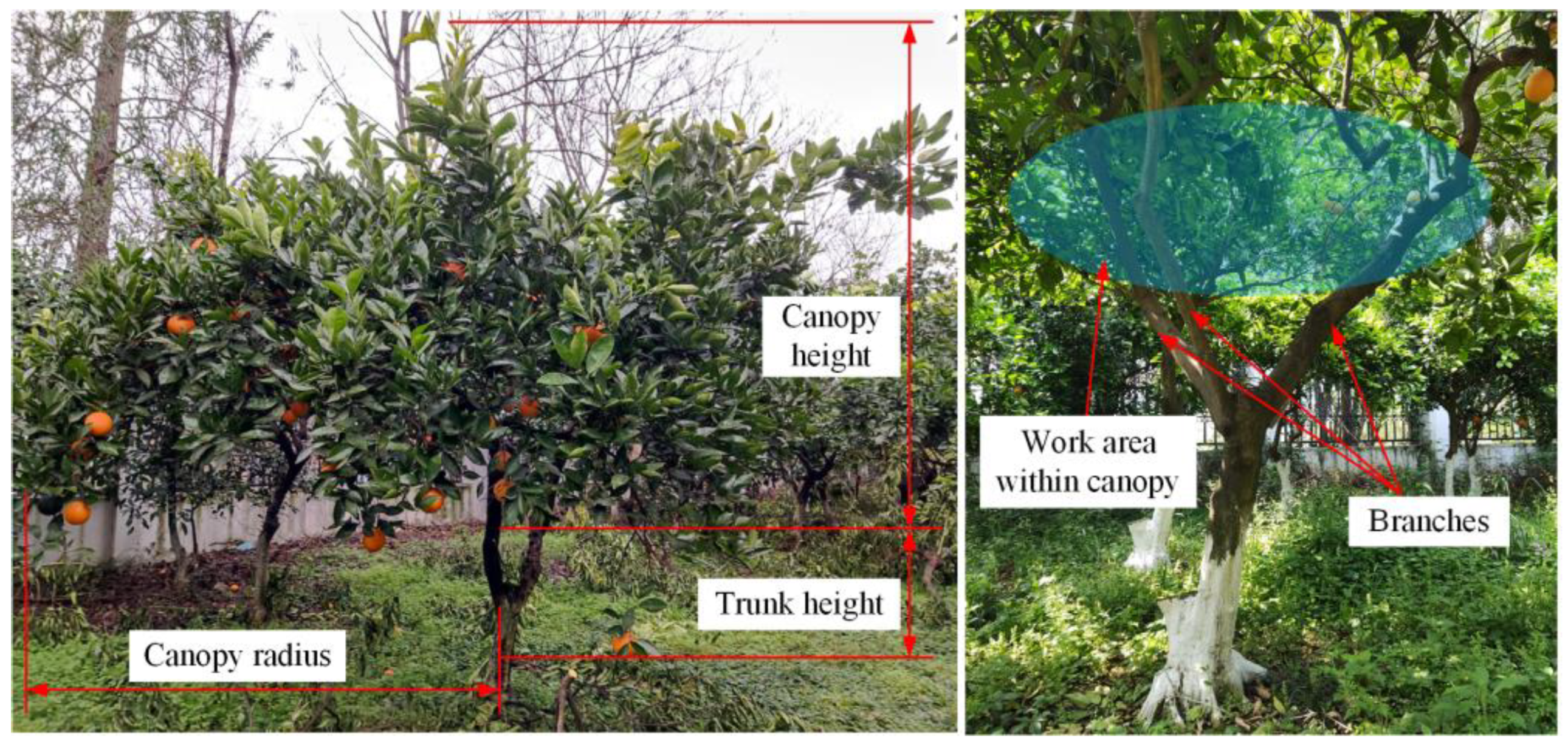
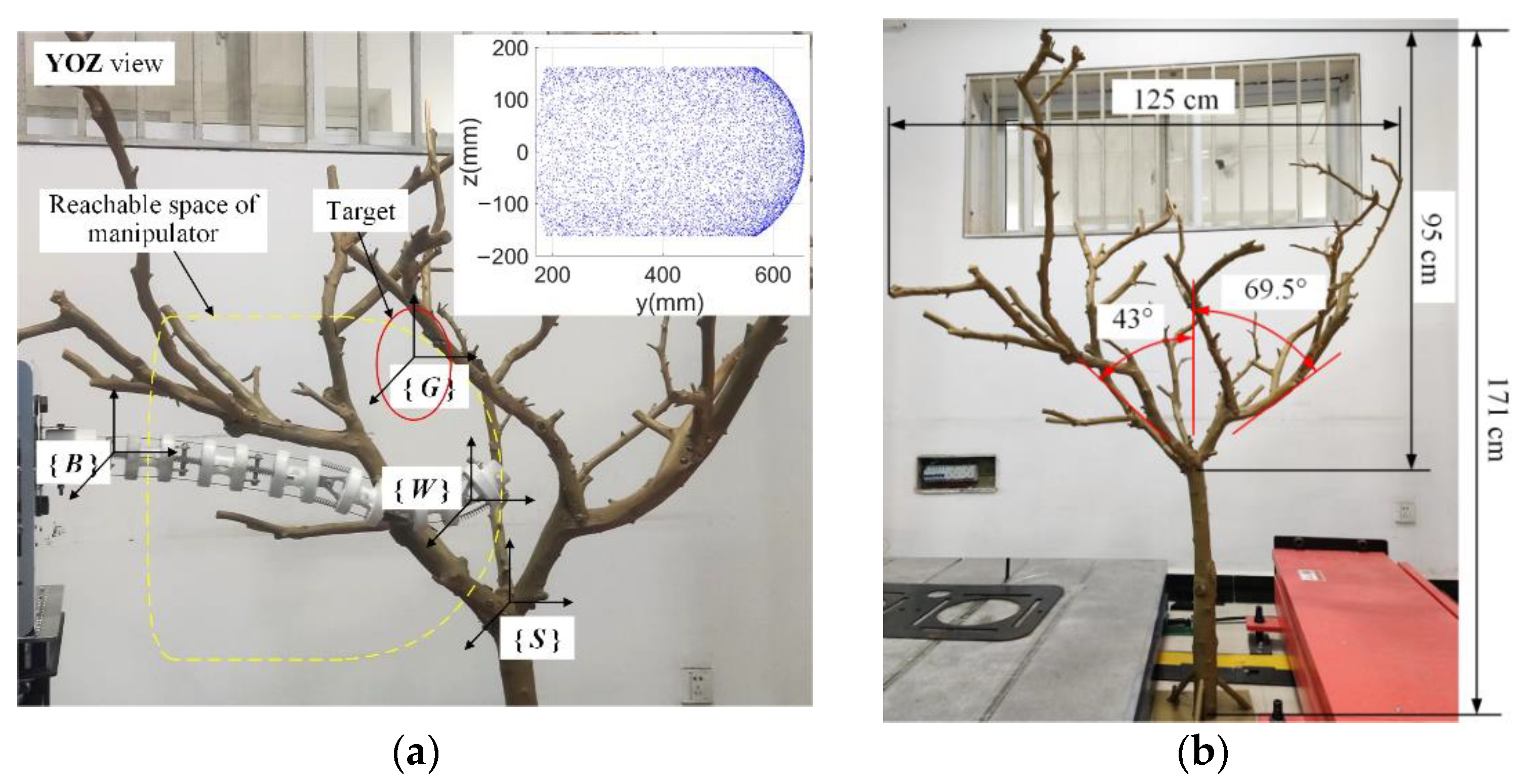
2.1. Working Environment Analysis

This spray robot was designed with dwarf citrus trees frequently planted in hilly areas as the research object. As shown in Figure 1, the average height of dwarf citrus trees is 1.5–3.5 m, the canopy height is 1.0–2.5 m, and the canopy radius is 1.25–2.5 m. The average width and length of citrus leaves are 4.5 cm and 8 cm, respectively.

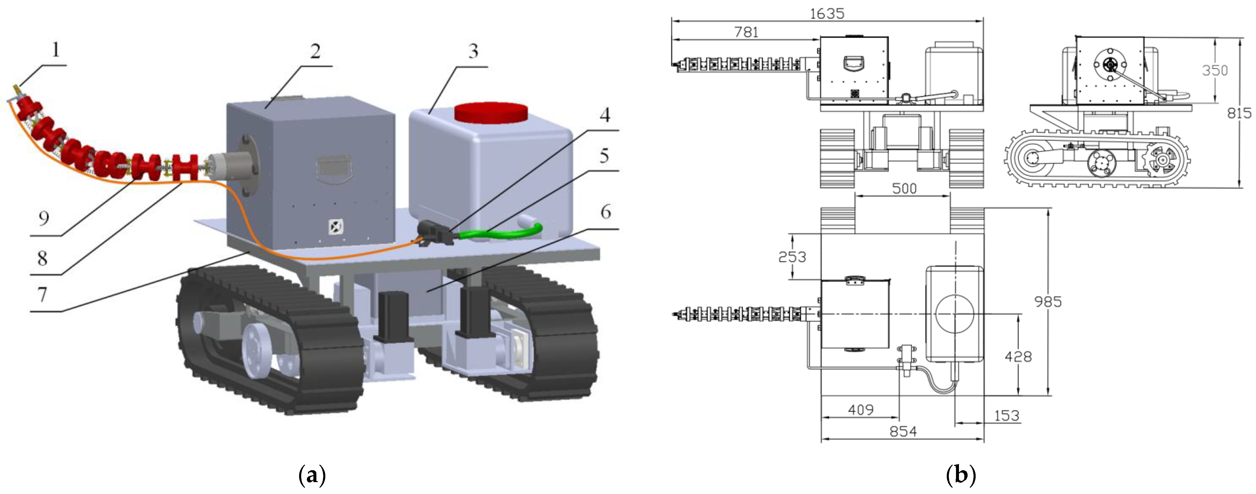
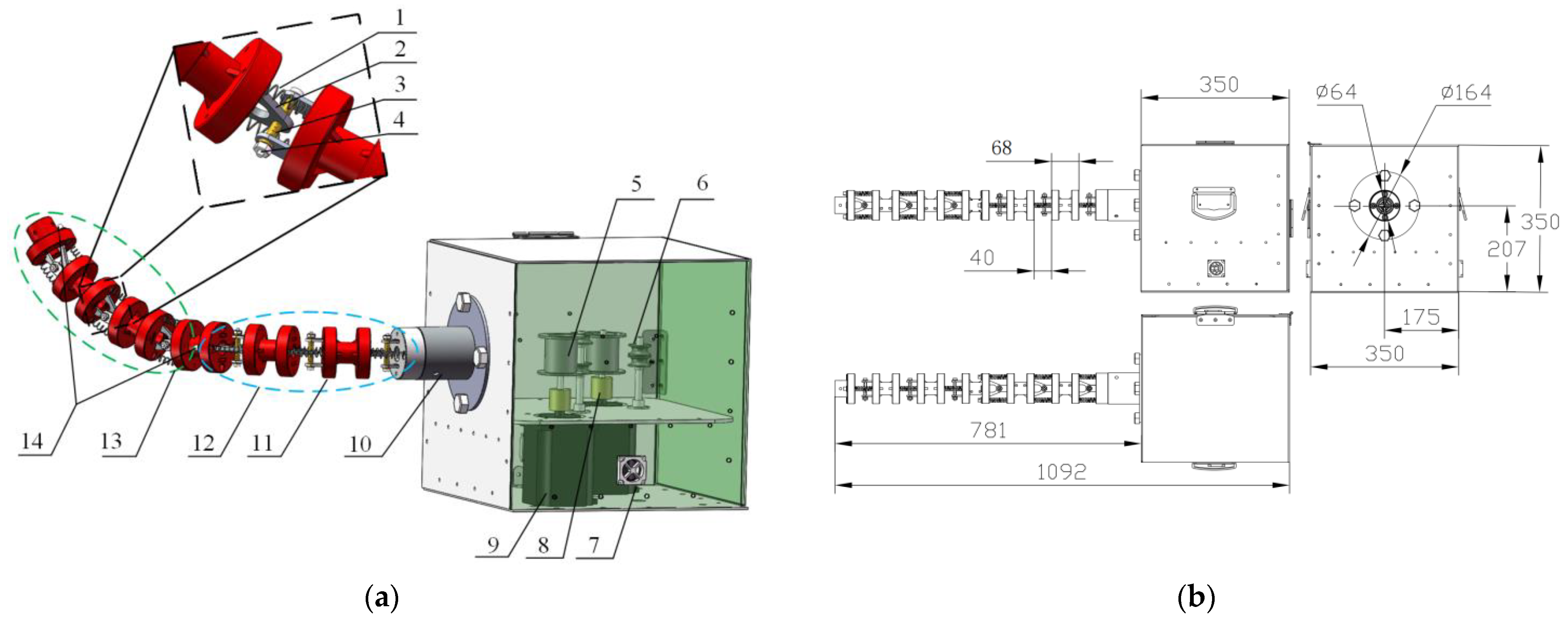
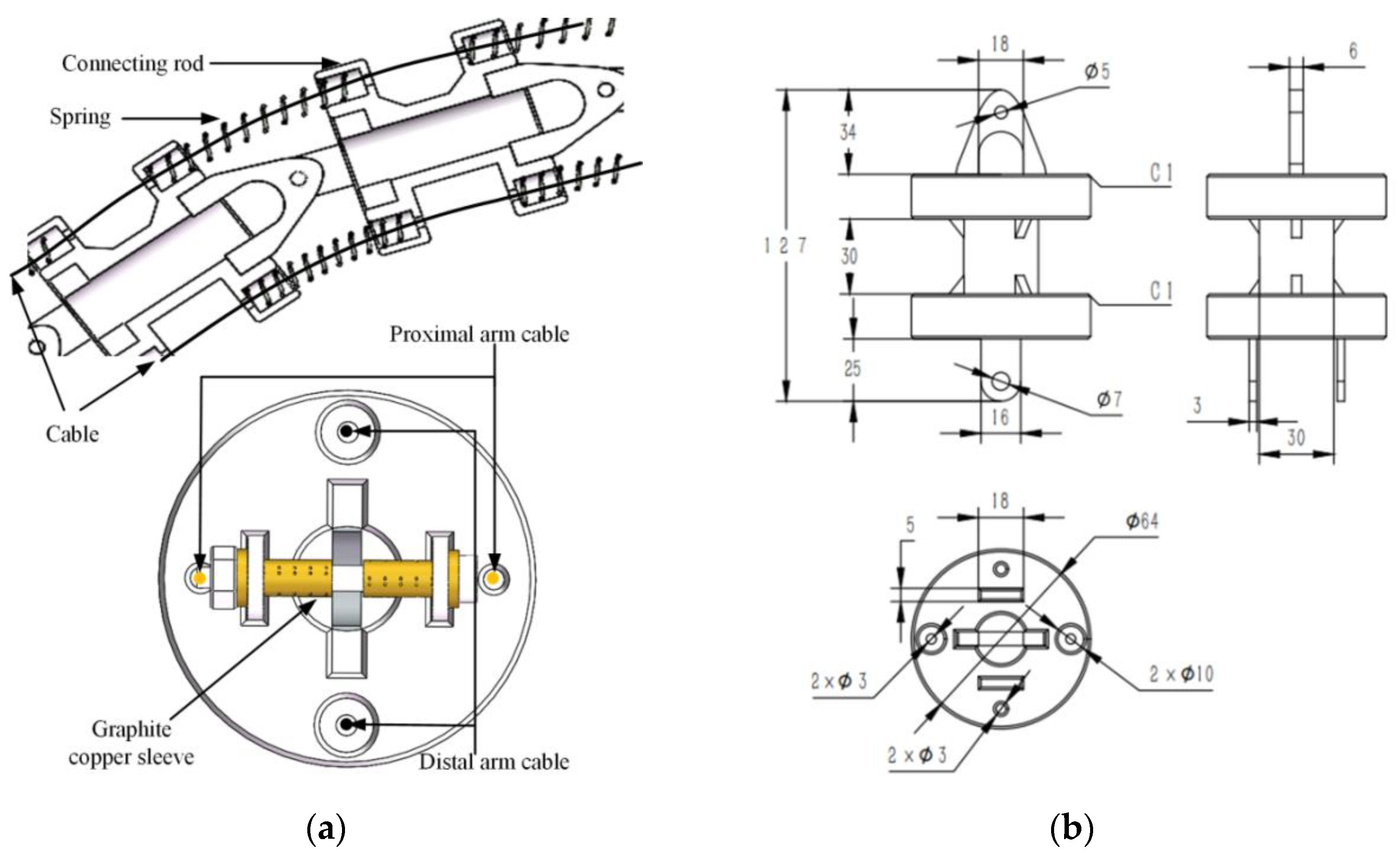
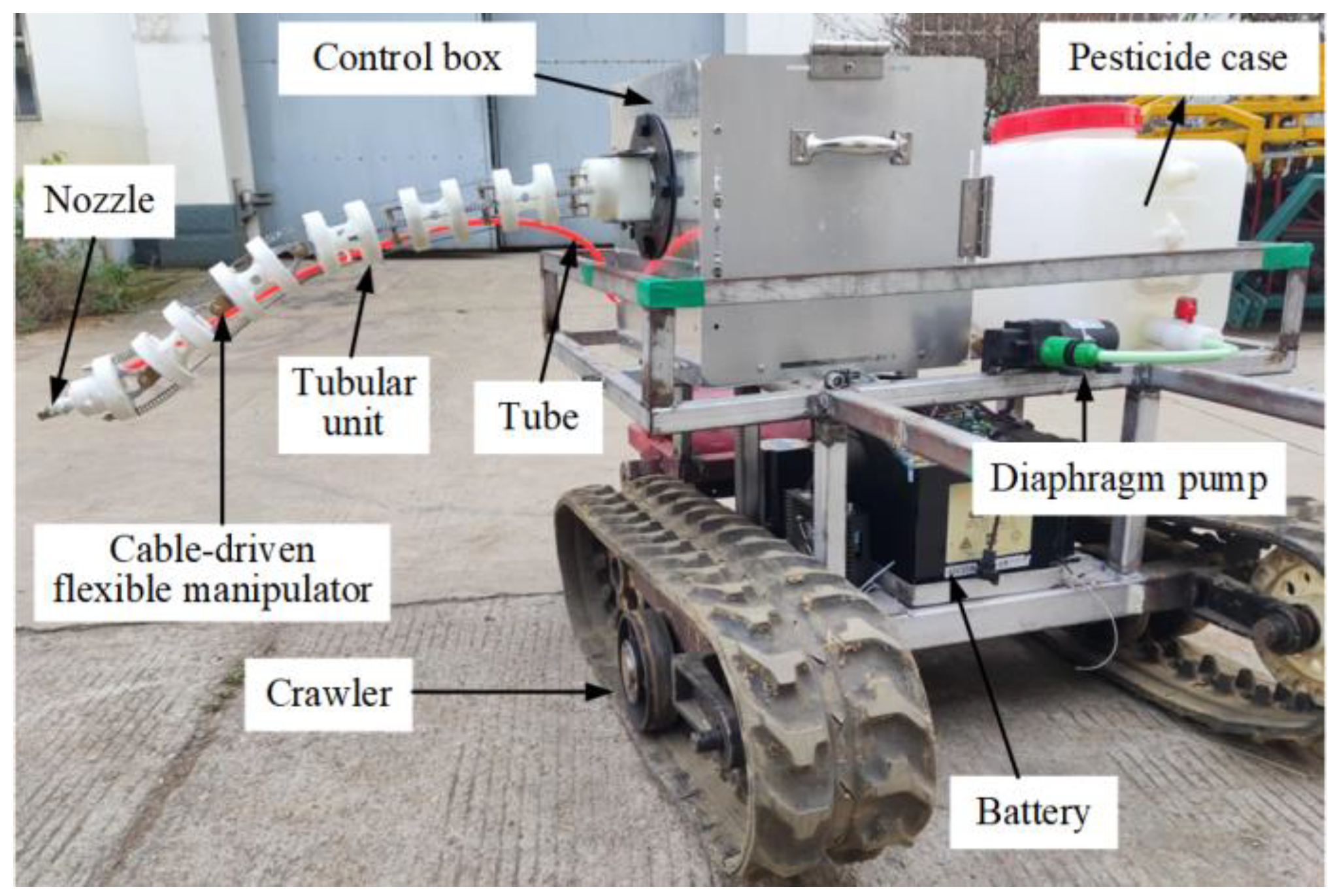
2.2. Mechanism Design of CDTSR

The CDTSR was designed in view of the above working environment. As shown in Figure 2, it mainly consisted of a tracked mobile platform, CDFM, and spray system. In addition, the manipulator and spray system were an integrated structure that can be directly installed on appropriate mobile platforms. The nozzle of the spray system was equipped at the end of the manipulator, the spray angle and distance of which could be adjusted.
The CDFM was a concentric tubular manipulator with six degrees of freedom. As shown in Figure 3, it consisted of a control box, a proximal arm segment, and a distal arm segment. Each arm segment was controlled by a motor that was equipped with a reel. Two cables were wound clockwise and counterclockwise on each reel, respectively, and were fixed on the last connecting rod of the arm segment through the cable locking. The proximal arm segment and the distal arm segment were connected by a connecting rod with a torsion angle of 90° to achieve a bending motion in the horizontal plane and in the vertical plane, respectively. With the cooperation of these two arm segments, this manipulator could reach any position in three-dimensional space.
The manipulator had six joints, each with the same structure; a single joint structure is shown in Figure 4a. The adjacent connecting rod was connected using a spring and hinge structure, which could transfer force through the spring. Therefore, it only needed to apply tension on the last connecting rod in the arm segment to make each joint rotate, thereby reducing the number of driving motors required and the difficulty of control. The shaft hole and shaft of the support were connected with a graphite copper sleeve to reduce the friction at the joint. The CAD drawings of the connecting rod are shown in Figure 4b.

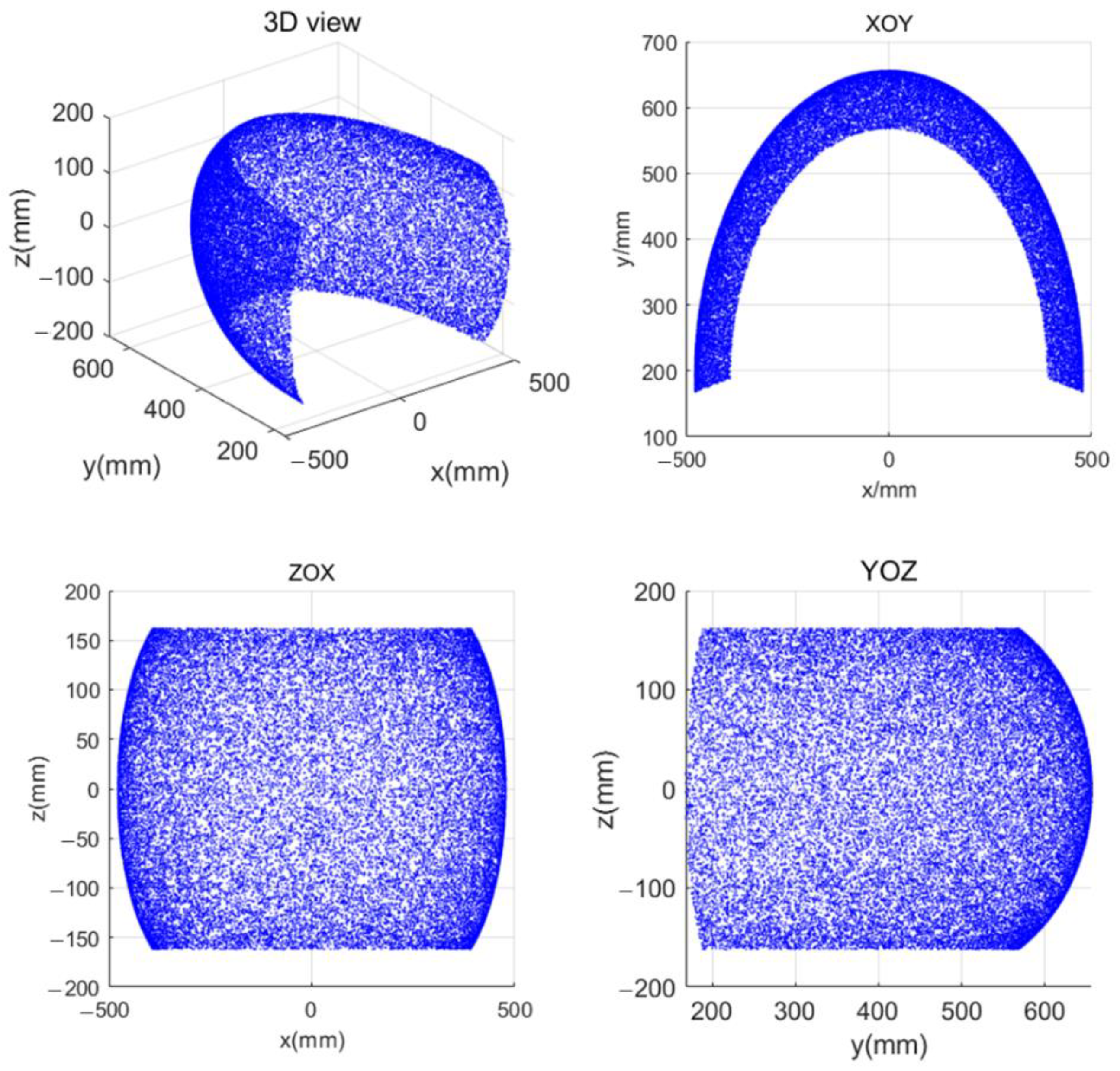
3. Kinematic Analysis of CDFM

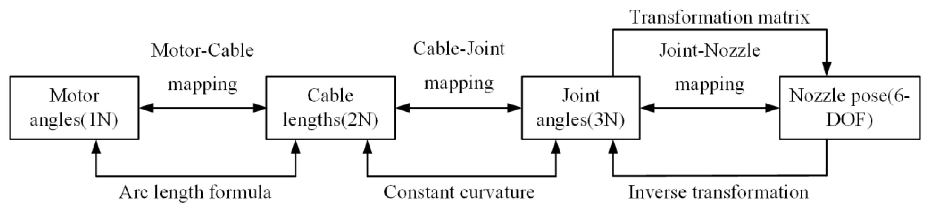
3.1. Multilevel Mapping Relationship of CDFM

The CDFM had six revolute joints but no joint motors. As shown in Figure 5, there was a multilevel mapping relationship between the motor and the end nozzle of the manipulator. The multilevel mapping relationship of the CDFM could be divided into the mapping relationship between the motor and the cable, the mapping relationship between the cable and the joint, and the relationship between the joint and the end. By establishing the multilevel mapping relationship of the manipulator, the pose of the end nozzle could be obtained under the condition of a known motor rotation angle.

3.2. Mapping between Motor and Cable

The motion of the driving cable was realized by the rotation of the motor. The mapping relationship between the cable length variable and the motor rotation angle was as follows:
Δ L k , i = Δ φ R
where Δ φ and Δ L k , i respectively denote the variations in the motor angle and cable length, and R is the winding radius of the cable (here, R = 32 mm).

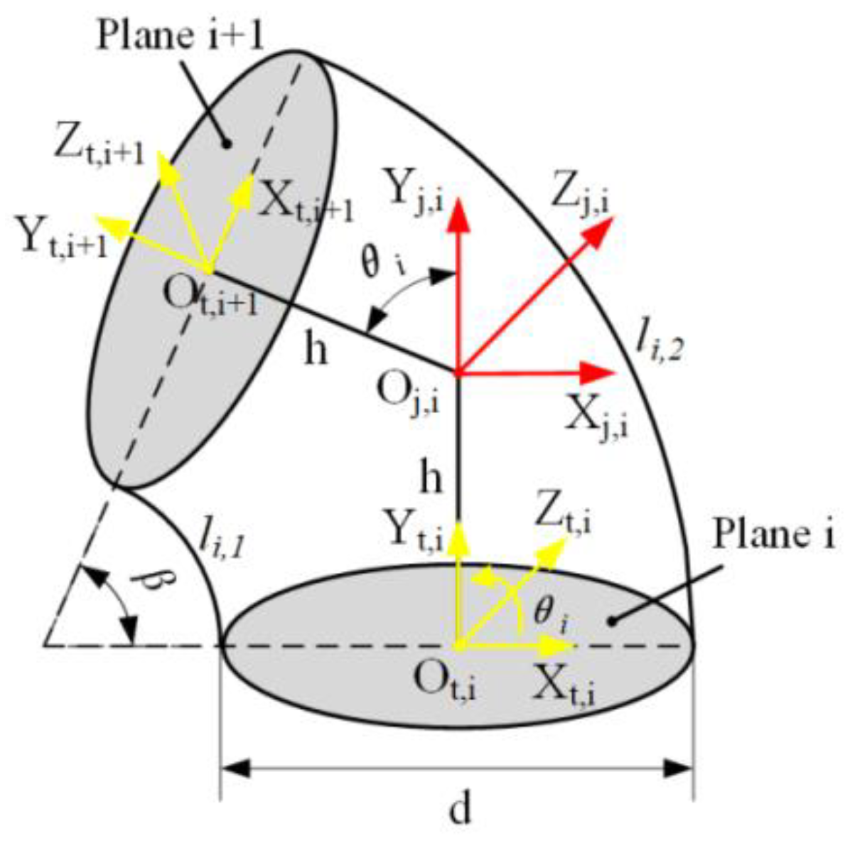
3.3. Mapping between Cable and Joint

To describe the kinematic relation between the cable and the joint of the CDFM, the tendon joint was assumed to have a constant curvature, thus allowing us to create a geometric model based on a constant-curvature assumption, as shown in Figure 6. The coordinate systems {O,i} and {Ot,i+1} existed in the center of the two discs with their Y-axes in the normal direction of the disc and X-axes and Z-axes in the radial direction of the disk. The coordinate system {Oj,i} was in the center of the hinge with the same posture as the coordinate system {Ot,i}.
The length of each driving cable could be derived by using (3), including the length inside the tubular structure and at the joint. The driving cable length inside the tubular structure was a constant that was equal to the length of the tubular structure, while the length of the cable at the joint was equal to the length of the spring. The spring at the joint bent when the joint rotated, and the bending curvature was a constant. There were two driving cables at each joint; one made the joint bend the active one, while the other was the slave. The relationship between the driving cable length and the joint angle at the i-th joint could be derived as follows:
l i , k = { 2 h d tan ( θ i 2 ) 2 tan ( θ i 2 ) θ i   ,   k = 1 , 3 2 h + d tan ( θ i 2 ) 2 tan ( θ i 2 ) θ i   ,   k = 2 , 4
L i , k = i = 1 6 ( l i , k + H )
where l i , k is the length of the k-th (k = 1, 2, 3, 4) cable at the i-th joint; θ i is the joint angle; h and d are constants that respectively denote the length of the bracket and the diameter of the rigid tubular structure (according to (2), when the joint angle was zero, the length of the driving cable at each joint was 2 h (2 h = 40 mm)); L i , k is the total length of the k-th driving cable for the first i joints; and H is the length of the rigid tubular structure.
Such continuum-style robots are typically composed of multiple arm segments with each consisting of multiple rigid rods and elastic elements such as springs [37]. Assuming approximately equal angles between the adjacent rods within each segment, the constant curvature was approximately valid for the robot without external loads and gravity [28]. Each arm segment of the manipulator designed in this paper was composed of multiple rigid rods and springs with the proximal segment moving in the horizontal direction, thus the influence of gravity could be ignored. Without considering the external load, the joint angles between the adjacent rods in the segment were equal. The relationship between each joint angle in the first segment is shown as follows:
θ 1 = θ 2 = θ 3
The distal arm segment moved in the vertical direction while only considering the external gravity load; the force is shown below in Figure 7.
According to formula (2), the relationship between the spring 2i and the elastic force 2i − 1 at the same joint i can be obtained as (5):
F 2 i F 2 i 1 = l i , 3 l i , 4 = 2 h d tan ( θ i 2 ) 2 h + d tan ( θ i 2 )
Assuming that the mass of each rod was concentrated in the centroid, the influence of gravity on spring deformation was derived by using the centralized mass method and the holistic method, for which there exists the following system of equations:
{ ( G 4 + G 5 + G 6 ) H 1 = ( F 2 i + F 2 i 1 ) d 2 ( G 5 + G 6 ) H 2 = ( F 2 ( i + 1 ) + F 2 ( i + 1 ) 1 ) d 2 G 6 H 3 = ( F 2 ( i + 2 ) + F 2 ( i + 2 ) 1 ) d 2
where F 2 i is the elastic force of the spring 2i; G 4 , G 5 , and G 6 respectively represent the gravity of rods 4, 5, and 6; H 1 is the distance vector of the gravity-resultant force point of rods 4, 5, and 6; H 2 is that of rods 5 and 6; and H 3 is the distance vector of the gravity point of rod 6. Based on formulas (2), (5), and (6), the relationship of the joint angles between the adjacent rods in the same segment was as follows:
θ 4 = ( m 4 + m 5 + m 6 ) H 1 ( m 5 + m 6 ) H 2 tan θ 4 tan θ 5 θ 5 = ( m 4 + m 5 + m 6 ) H 1 m 6 H 2 tan θ 4 tan θ 6 θ 6
where m 4 , m 5 , and m 6 respectively denote the mass of rod 4, rod 5, and rod 6.

3.4. Kinematics between Joint and End

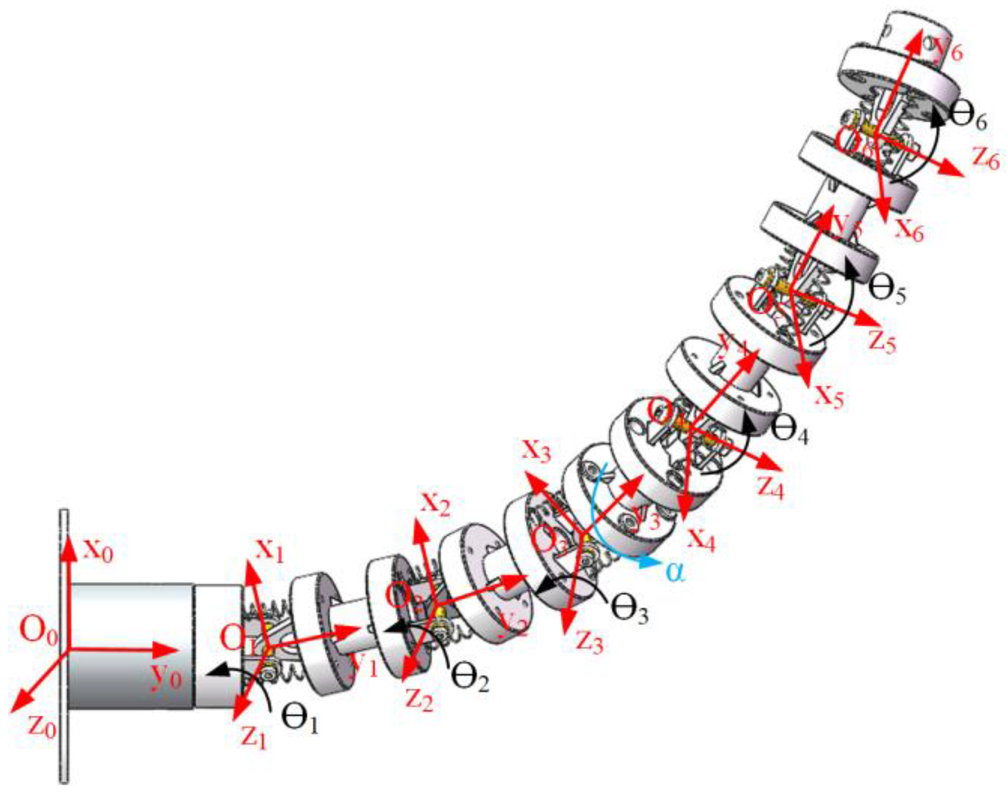
3.4.1. Forward Kinematics

To obtain the position and attitude of the end of the CDFM, the kinematics model was established based on the D-H method using a transformation matrix. The coordinate system of the flange foundation O0 was named as the base frame {O0} and the coordinate system of each joint was named as {O1}, {O2}, {O3}, {O4}, {O5}, and {O6}, as shown in Figure 8. The origin of the coordinate system was the centroid of the joint. When the joint angle of each joint was 0°, the coordinate systems {O1}, {O2}, and {O3} were completely in the same direction and the coordinate systems {O4}, {O5}, {O6} were completely in the same direction.
The kinematic equation between the joint variable and the end pose of the CDFM was derived from Equation (8) by multiplying the transformation matrix from the based coordinate system {O0} to the end coordinate system {O6}.
T 6 0 = T 1 0 T 2 1 T 3 2 T 4 3 T 5 4 T 6 5 = [ n x 6 o x 6 a x 6 p x 6 n y 6 o y 6 a y 6 p y 6 n z 6 o z 6 a z 6 p z 6 0 0 0 1 ]
The D-H parameters of the CDFM are shown in Table 1.

3.4.2. Inverse Kinematics

According to the known end pose of the CDFM, each joint angle could be calculated by using the inverse transformation method. The joint angles θ 1 , θ 2 , θ 3 of the first segment were equal, with their closed solution being deduced as follows:
θ 1 = θ 2 = θ 3 = a tan 2 ( n y 6 o z 6 a x 6 , o z 6 a y 6 + n x 6 )
The closed joint of joint angles θ 4 , θ 5 , θ 6 of the distal arm segment was derived as follows:
θ 4 = ( m 4 + m 5 + m 6 ) H 1 ( m 5 + m 6 ) H 2 tan θ 4 tan θ 5 θ 5 = ( m 4 + m 5 + m 6 ) H 1 m 6 H 2 tan θ 4 tan θ 6 θ 6 = 1 3 a tan 2 ( o z 6 , n z 6 )
According to formulas (1), (2), (3), (9), and (10), the corresponding motor rotation angle at any position could be obtained. Then, the CDFM could be controlled in real time according to the established kinematics model.

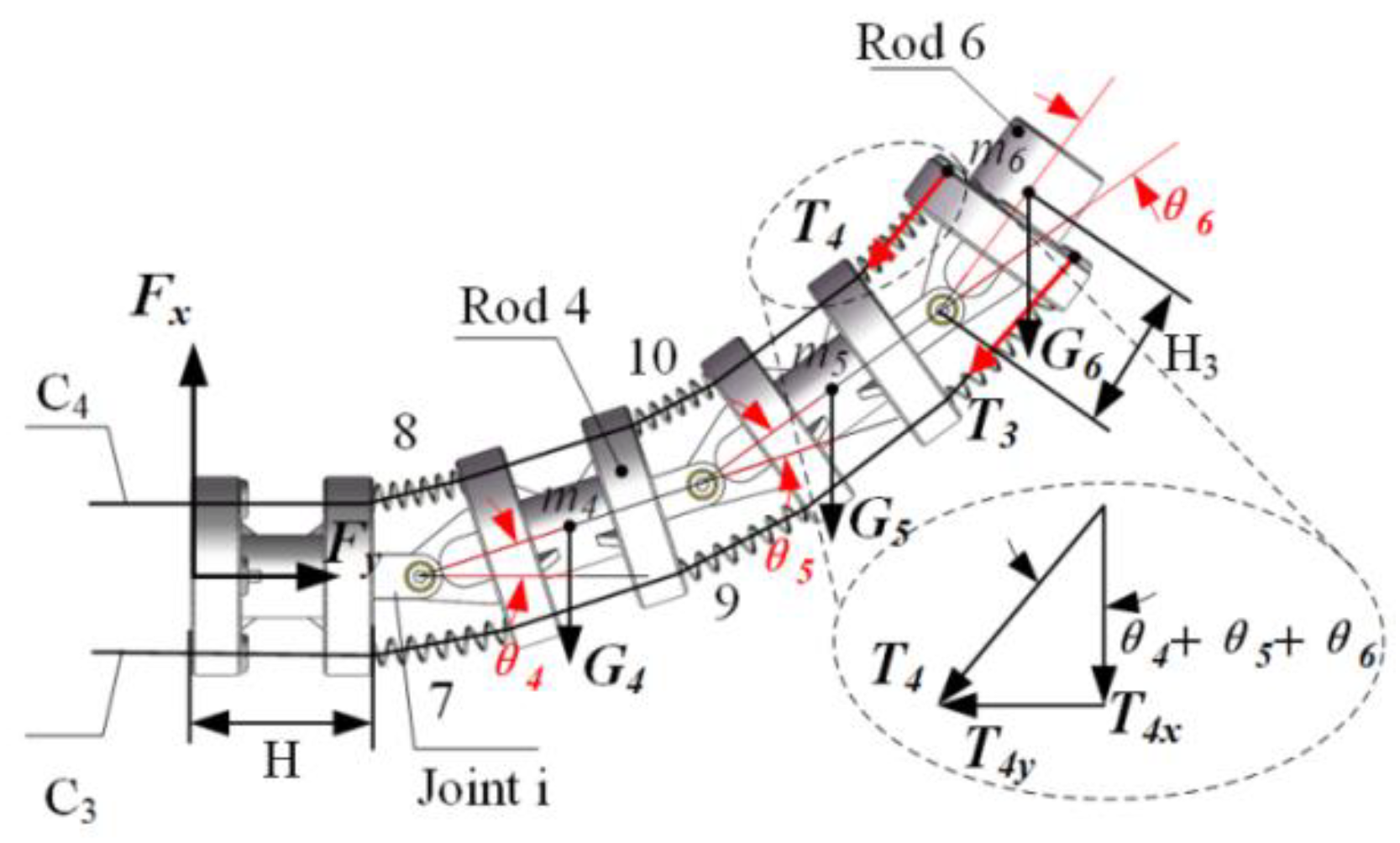
4. Dynamic Analysis of CDFM

A dynamic analysis was conducted to obtain the relation between the motor torque and the speed of the manipulator end. Without considering the energy of friction loss, the energy generated by the motor was equal to the sum of the kinetic energy and potential energy of the system. In the operating space, the dynamic equation established according to energy conservation law is shown as follows:
W = E k + E p
where E k is the total kinetic energy of the CDFM system, E p is the total potential energy of the CDFM system, and W is the work done by the motor. The CDFM had six rods with θ · = [ θ · 1 , θ · 2 , θ · 3 , ... , θ · 6 ] representing the angular velocity of the rod centroid and v c i = [ v c 1 , v c 2 , v c 3 , ... , v c 6 ] denoting the linear velocity of the rod centroid. The kinetic energy of the first n rods of the system could be derived according to formula (12):
E k n = 1 2 i = 1 n m i v c i 2 + 1 2 i = 1 n I z z i θ · i 2
where I z z i is the rotational inertia of rod (i) around the Z-axis and m i denotes the mass of rod (i). The mass and centroid coordinates of each rod of the CDFM are shown below in Table 2.
The inertia tensor of each rod of the CDFM was as follows (the unit is k g × m m 2 ).
I c 1 = I c 2 = I c 4 = I c 5 = [ 205.093 0.071 0 0.071 111.425 0.190 0 0.190 194.877 ] I c 3 = [ 199.522 0.010 0 0.010 108.268 0.094 0 0.094 190.308 ] I c 6 = [ 44.973 0.033 0 0.033 54.498 0 0 0 43.812 ]
The potential energy of the system was composed of gravity potential energy and elastic potential energy. The potential energy of the first n (n ≤ 6) connecting rod of the system could be determined as follows:
E p n = 1 2 i = 1 n K 2 i 1 Δ x 2 i 1 2 + i = 3 n m i H c i g sin θ i
where Δ x 2 i 1 2 represents the deformation quantity of the spring 2i−1; H c i represents the distance between the centroid of connecting rod (i) and the shaft; and K 2 i 1 (i = 1,…,6) represents the stiffness coefficient of the spring 2i−1, which could be calculated using the following equation:
K 2 i 1 = G d 4 8 D 3 n
where G is the stiffness coefficient; d and D represent the cable diameter and mean diameter of the spring, respectively; and n is the number of effective cycles. The motor torques could be determined as follows:
M = E k n + E p n φ
where M is the motor torque and φ is the motor turning angle.

5. Prototype and Experiments

5.1. Prototype Building and Performance Testing

As shown in Figure 9, the prototype used in this experiment was composed mainly of a CDFM, an automatic spray-control system, and a tracked mobile platform. The main technical parameters of the prototype are shown in Table 3.
The radius of the tubular unit was 40 mm and the distance from the adjacent end plate was 32 mm. Based on the established kinematics equation, the reachable space of the robot was obtained by using the Monte Carlo random point method, as shown in Figure 10. From a fixed base, the reachable workspace was semispherical.
The deformation of the cable will affect the accuracy of the manipulator, thus 304 stainless steel cable with better rigidity and flexibility was chosen. The spring was composed of carbon steel while the tubular unit was composed of resin and created via 3D printing. The control box required a sufficient strength and a light weight, so we choose aluminum to manufacture the control box.
The repeated location accuracy measured by using the dial gauge was 0.532. To test the flexibility of the CDFM, a branch obstacle avoidance experiment was designed. The CDFM needed to circumvent the branches and enter into the tree canopy to achieve target spraying. The reachable space and position of the manipulator to the model tree are shown in Figure 11a; the size of the model tree is shown in Figure 11b. The 3D model of the model tree was established by using a Ready Scan B11 3D scanner and placing the model tree and the manipulator under the same coordinate system. According to the coordinate position of the obstacles, the motor rotation angle was obtained by using the established kinematics model. Through programming of the upper machine, the motion trajectory of the manipulator was determined. Then the manipulator could avoid obstacles according to predetermined trajectory. The sensor and camera could also be installed to realize automatic obstacle avoidance. However, a method to achieve a more effective automatic obstacle avoidance remains to be explored.
The experimental process is demonstrated in Figure 12. After placing the model tree into the workspace of the manipulator, the manipulator firstly avoided obstacle 2, then passes through the narrow space between obstacles 1 and 2, and finally avoided obstacle 1 and entered into the canopy. The experimental results proved that the manipulator had a good obstacle avoidance performance that could avoid the branches and reach the inner part of the tree canopy.

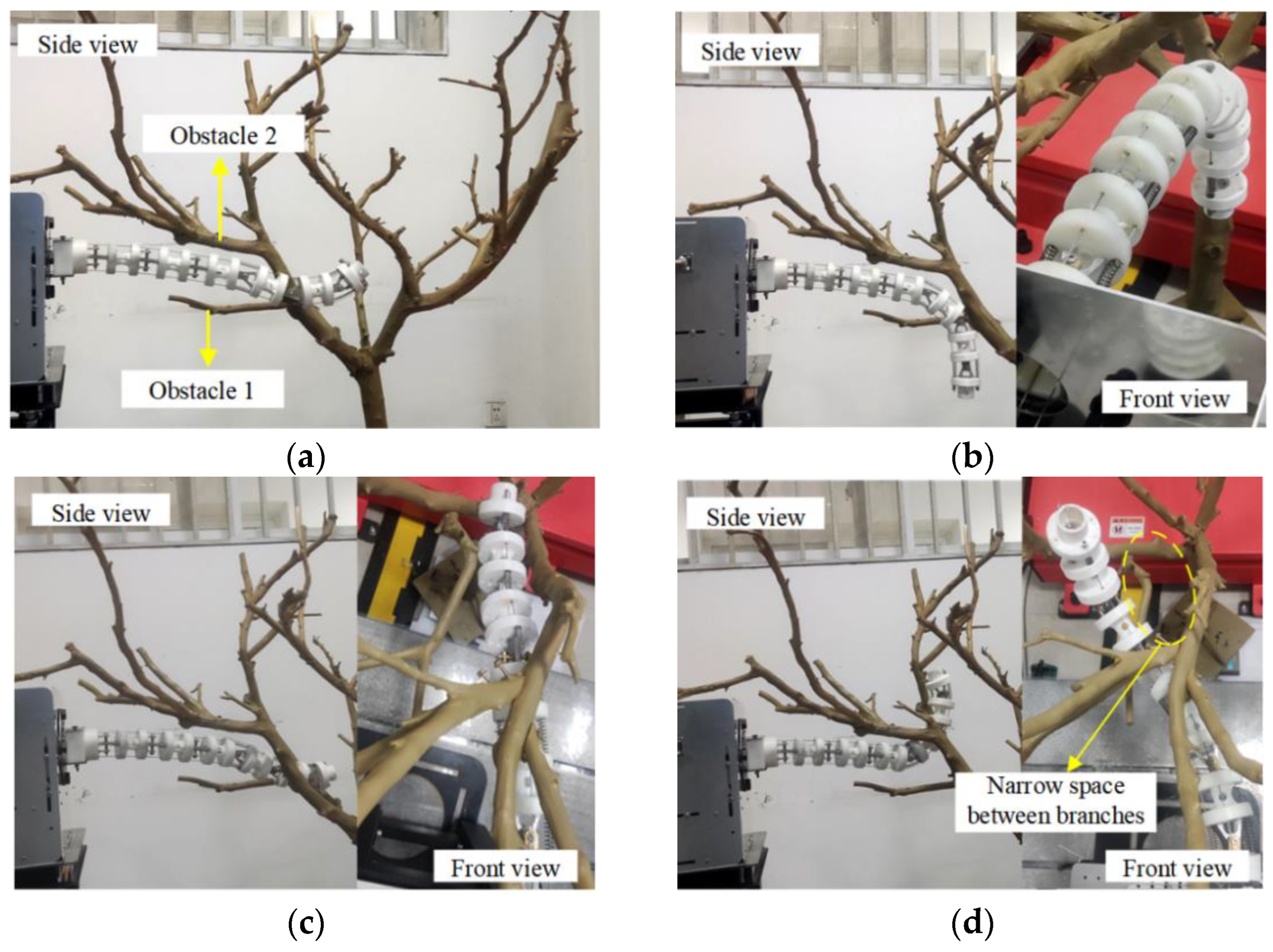
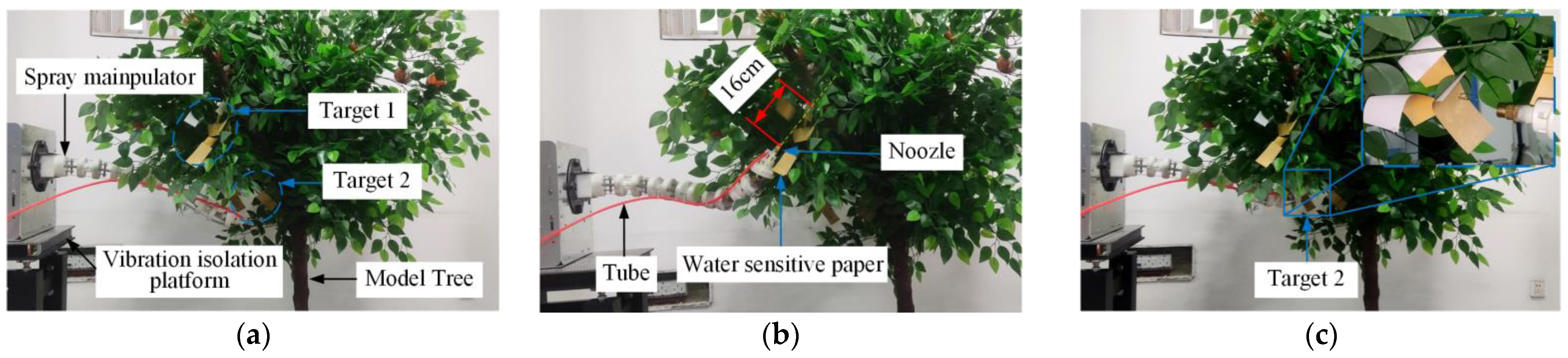
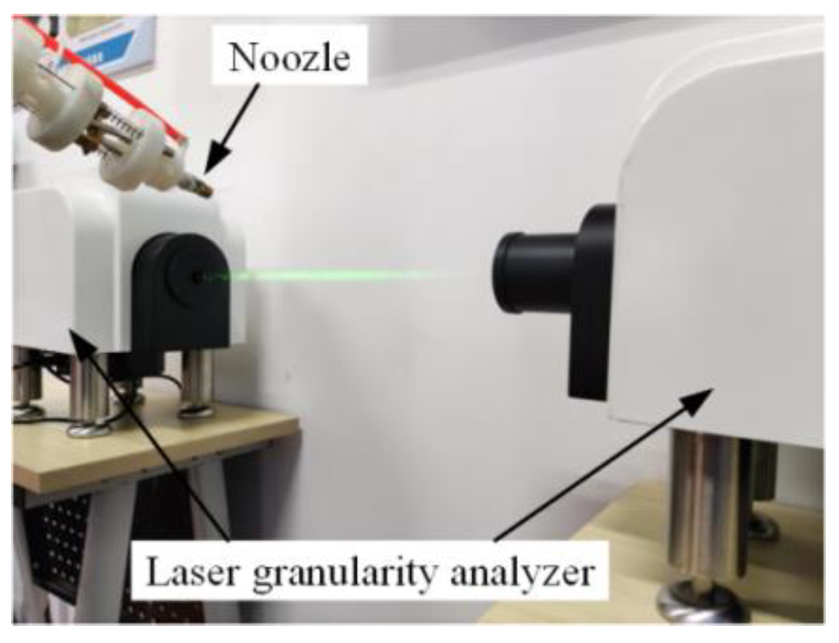
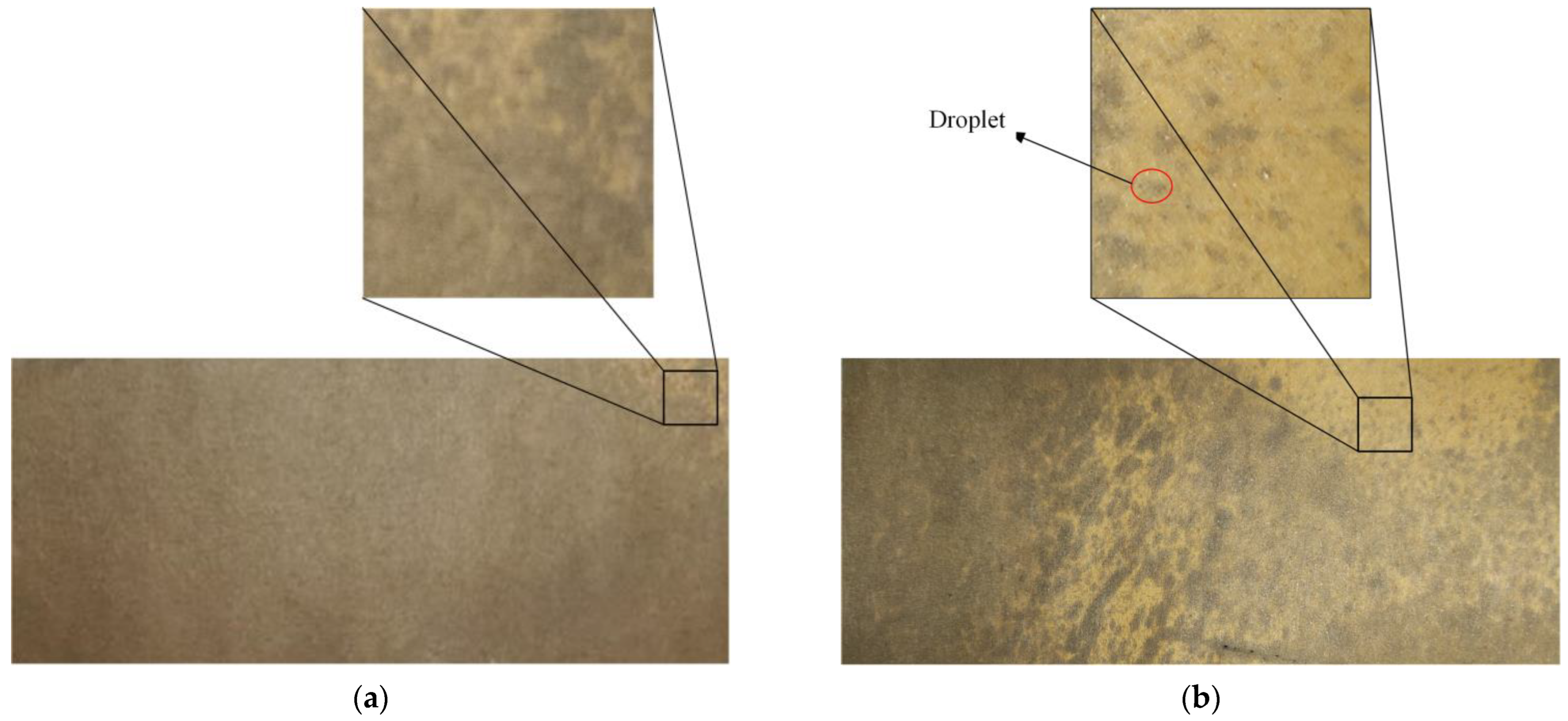
5.2. Spraying Experiment

The pest-affected areas of the tree canopy were the targets of the spraying. To verify the effects of the cable-driven flexible spray manipulator, a target-spraying experiment was performed on target 1 in the middle of the canopy and target 2 in the inner canopy in turn, as shown in Figure 13. The height of the model tree was 1.67 m. The canopy height ranged from 0.69 m to 1.67 m and its diameter was 1.53 m. The mass of the nozzle was 10.6 g. The end of our manipulator did not have an extra load and the tube was evenly distributed on the manipulator. The manipulator moved smoothly throughout the entire operation.
The spray manipulator was operated via remote control. The length of the nozzle was about 3 cm and the distance between the nozzle and the water-sensitive paper directly in front of it was 16 cm. After 0.5 s, the spray system began spraying; the entire spraying process lasted for 3.5 s. The manipulator had a variable stiffness manipulator; the stiffness was related to the spring of the manipulator. The interference generated by the spray was along the axial direction of the manipulator in the spray without a large amount of shaking, which ensured the accuracy of the spray. During the entire operation, the manipulator moved smoothly and rarely vibrated when the spraying system was working. Although the manipulator could avoid tree branches in its movement process, it also was obstructed by the leaves. The external interference force from the leaves also affected the accuracy of the manipulator, the workspace for which was not large enough, thus it is necessary to increase its workspace and multiple-orientation abilities in the future.
As shown in Figure 14, the droplet size was tested using a laser granularity analyzer. The spray angle was 60° and the diameter of the spray hole was 0.8 mm. When the spray flow rate was 4.0 mL/s, the droplet diameter was 97.617 μm. The droplets were collected on water-sensitive paper and data processing was conducted to obtain the deposition and coverage rate of the droplets, as shown in Table 4.
The droplet coverage rate of each piece of water-sensitive paper was measured using image processing. The water-sensitive paper changed from a light yellow to grayish when exposed to water. When the spray flow rate was 4.0 mL/s, the center coverage rate and edge coverage rate were 98.4% and 64.3%, respectively, as shown in the sample images in Figure 15. Therefore, the experimental results showed that the droplet coverage rate descended gradually from the spraying center to the outside.
The average coverage within the canopy of conventional spraying equipment is 32.8% [11]. The CDTSR improved coverage within the canopy compared to conventional spraying equipment. The working space and dexterity also were enhanced. In the future, we will reduce the weight of the CDFM and the ability of the manipulator to achieve multiple orientations will be improved. Meanwhile, the CDTSR can work in collaboration with plant protection UAVs and small spraying equipment in the future.

6. Conclusions

In this article, a CDTSR that could be driven below the canopy was designed. The target spray robot had a dexterity CDFM that could avoid branches and penetrate into the canopy to achieve precise spraying without causing mechanical damage to the fruit trees.
In addition, a kinematics analysis of the CDFM was carried out and the arc length formula was used to solve the mapping relationship between the motor and the driving cable. According to the geometric model of the manipulator, the mapping relationship between the length of the driving cable and the joint angle was established based on the constant curvature assumption. The kinematics model between the manipulator joint and the end actuator was established by using the transformation matrix. Therefore, the multilevel mapping relationship among the motor, driving cable, joint, and end actuator could be clearly described. The workspace of the manipulator was calculated using the Monte Carlo random point method; the calculation results verified the correctness of the kinematics model. To obtain the relationship between the position and velocity of the manipulator end and the motor torque, a dynamic equation for the manipulator was established. In the spraying experiment, the cable was tightened at a constant speed of 0.2 m/s and the manipulator could move steadily from the initial state to any target in the workspace within 3.5 s and stop steadily. The spraying experiment showed an 88.0% droplet deposition rate and a 64.3% coverage rate within the canopy. The average coverage within the canopy was increased by 31.5% compared to the conventional spraying equipment. In the future work, a visual system and more sensors will be added to the spray robot to target acquisition and obstacle avoidance path planning automatically.

Author Contributions

Conceptualization, X.B. and Y.N.; methodology, X.B.; software, X.B. and Y.N.; validation, X.B., Y.N. and S.L.; formal analysis, Y.N. and S.L.; investigation, Y.N.; resources, J.M.; data curation, Y.L.; writing—original draft preparation, X.B., Y.N. and Y.L.; writing—review and editing, X.B. and Y.N.; visualization, Q.Y.; supervision, X.B. and B.C.; project administration, X.M. and X.B.; funding acquisition, J.M. All authors have read and agreed to the published version of the manuscript.

Funding

This research was funded by the Natural Science Foundation of Hubei Province, China (No. 2021CFB 471) and the National Key Research and Development Program of China (No. 2018YFD0700804).

Institutional Review Board Statement

Not applicable.

Informed Consent Statement

Not applicable.

Data Availability Statement

Not applicable.

Conflicts of Interest

The authors declare no conflict of interest.

References

  1. Zhao, Y.; Xiao, H.; Mei, S.; Song, Z.; Ding, W.; Jing, Y.; Xia, X.; Yang, G. Current status and development strategies of orchard mechanization production in China. J. Chin. Agric. Univ. 2017, 22, 116–127. [Google Scholar]
  2. Hong, S.W.; Zhao, L.; Zhu, H. CFD simulation of airflow inside tree canopies discharged from air-assisted sprayers. Comput. Electron. Agric. 2018, 149, 121–132. [Google Scholar] [CrossRef]
  3. He, X. Research progress and developmental recommendations on precision spraying technology and equipment in China. Smart Agric. 2020, 2, 133–146. [Google Scholar]
  4. Song, S.; Sun, D.; Xue, X.; Dai, Q.; Li, Z.; Li, Z.; Hong, T. Design of pipeline constant pressure spraying equipment and facility in mountainous region orangery. In Proceedings of the 6th IFAC Conference on Bio-Robotics, Beijing, China, 13–15 July 2018. [Google Scholar]
  5. Zheng, Y.; Chen, B.; Lv, H.; Kang, F.; Jiang, S. Research progress of orchard plant protection mechanization technology and equipment in China. Trans. CSAE 2020, 36, 110–124. [Google Scholar]
  6. Sharda, A.; Karkee, M.; Hoheisel, G.; Zhang, Q.; Mangus, D. Design and Evaluation of Solid Set Canopy Delivery System for Spray Application in High-density Apple Orchards. Appl. Eng. Agric. 2019, 35, 751–757. [Google Scholar] [CrossRef]
  7. Wang, X.; Zhu, H.; Reding, M.E.; Locke, J.C.; Leland, J.E.; Derksen, R.C.; Spongberg, A.L.; Krause, C.R. Delivery of chemical and microbial pesticides through drip irrigation systems. Appl. Eng. Agric. 2009, 25, 883–893. [Google Scholar] [CrossRef]
  8. Ranjan, R.; Sinha, R.; Khot, L.R.; Hoheisel, G.A.; Grieshop, M.; Ledebuhr, M. Spatial distribution of spray from a solid set canopy delivery system in a high-density apple orchard retrofitted with modified emitters. Appl. Sci. 2021, 11, 709. [Google Scholar] [CrossRef]
  9. Salcedo, R.; Zhu, H.; Zhang, Z.; Wei, Z.; Chen, L.; Ozkan, E.; Falchieri, D. Foliar deposition and coverage on young apple trees with PWM-controlled spray systems. Comput. Electron. Agric. 2020, 178, 105794. [Google Scholar] [CrossRef]
  10. Ma, C.; Li, G.; Peng, Q. Design and Test of a Jet Remote Control Spraying Machine for Orchards. AgriEngineering 2021, 3, 797–814. [Google Scholar] [CrossRef]
  11. Shen, Y.; Zhu, H.; Liu, H.; Chen, Y.; Ozkan, E. Development of a laser-guided, embedded-computer-controlled, air-assisted precision sprayer. Trans. ASABE 2017, 60, 1827–1838. [Google Scholar] [CrossRef]
  12. Fessler, L.; Fulcher, A.; Lockwood, D.; Wright, W.; Zhu, H. Advancing sustainability in tree crop pest management: Refining spray application rate with a laser-guided variable-rate sprayer in apple orchards. HortScience 2020, 55, 1522–1530. [Google Scholar] [CrossRef]
  13. Escolà, A.; Rosell-Polo, J.R.; Planas, S.; Gil, E.; Pomar, J.; Camp, F.; Llorens, J.; Solanelles, F. Variable rate sprayer. Part 1-Orchard prototype: Design, implementation and validation. Comput. Electron. Agric. 2013, 95, 122–135. [Google Scholar] [CrossRef]
  14. Manandhar, A.; Zhu, H.; Ozkan, E.; Shah, A. Techno-economic impacts of using a laser-guided variable-rate spraying system to retrofit conventional constant-rate sprayers. Precis. Agric. 2020, 21, 1156–1171. [Google Scholar] [CrossRef]
  15. Palleja, T.; Landers, A.J. Real time canopy density estimation using ultrasonic envelope signals in the orchard and vineyard. Comput. Electron. Agric. 2015, 115, 108–117. [Google Scholar] [CrossRef]
  16. Zhou, L.; Zhang, L.; Xue, X.; Ding, W.; Sun, Z.; Zhou, Q.; Cui, L. Design and experiment of 3WQ-400 double air-assisted electrostatic orchard sprayer. Trans. CSAE 2016, 32, 45–53. [Google Scholar]
  17. Qiu, W.; Sun, H.; Sun, Y.; Liao, Y.; Zhou, L.; Wen, Z. Design and test of circulating air-assisted sprayer for dwarfed orchard. Trans. CSAE 2021, 37, 18–25. [Google Scholar]
  18. Pergher, G.; Gubiani, R.; Cividino, S.R.; Dell’Antonia, D.; Lagazio, C. Assessment of spray deposition and recycling rate in the vineyard from a new type of air-assisted tunnel sprayer. Crop. Prot. 2013, 45, 6–14. [Google Scholar] [CrossRef]
  19. Wang, C.; He, X.; Zeng, A. Measuring method and experiment on spray drift of chemicals applied by UAV sprayer based on an artificial orchard test bench. Trans. CSAE 2020, 36, 56–66. [Google Scholar]
  20. Wen, S.; Zhang, Q.; Deng, J.; Lan, Y.; Yin, X.; Shan, J. Design and experiment of a variable spray system for unmanned aerial vehicles based on PID and PWM control. Appl. Sci. 2018, 8, 2482. [Google Scholar] [CrossRef]
  21. Guler, H.; Zhu, H.; Ozkan, H.E.; Derksen, R.C.; Yu, Y.; Krause, C.R. Spray characteristics and drift reduction potential with air induction and conventional flat fan nozzles. Trans. ASABE 2007, 50, 745–754. [Google Scholar] [CrossRef]
  22. Chen, Y.; Zhu, H.; Ozkan, E.; Derksen, R.C.; Krause, C.R. Spray drift and off-target loss reductions with a precision air-assisted sprayer. Trans ASABE 2013, 56, 1273–1281. [Google Scholar]
  23. Wang, C.; Song, J.; He, X.; Wang, Z.; Wang, S.; Meng, Y. Effect of flight parameters on distribution characteristics of pesticide spraying droplets deposition of plant-protection unmanned aerial vehicle. Trans. CSAE 2017, 33, 109–116. [Google Scholar]
  24. Qiu, W.; Sun, C.; Lv, X.; Ding, W.; Feng, X. Effect of air-assisted spray application rate on spray droplet deposition distribution on fruit tree canopies. Appl. Eng. Agric. 2016, 32, 739–749. [Google Scholar]
  25. Zhou, Q.; Tang, J.; Nie, Y.; Chen, Z.; Qin, L. Visual Tracking Control of Cable-Driven Hyper-Redundant Snake-Like Manipulator. Appl. Sci. 2021, 11, 6224. [Google Scholar] [CrossRef]
  26. Tang, J.; Zhang, Y.; Huang, F.; Li, J.; Chen, Z.; Song, W.; Zhu, S.; Gu, J. Design and kinematic control of the cable-driven hyper-redundant manipulator for potential underwater applications. Appl. Sci. 2019, 9, 1142. [Google Scholar] [CrossRef]
  27. Duan, J.; Wang, B.; Cui, K.; Dai, Z. Path Planning Based on NURBS for Hyper-Redundant Manipulator Used in Narrow Space. Appl. Sci. 2022, 12, 1314. [Google Scholar] [CrossRef]
  28. Xu, W.; Liu, T.; Li, Y. Kinematics, dynamics, and control of a cable-driven hyper-redundant manipulator. IEEE ASME Trans. Mechatron. 2018, 23, 1693–1704. [Google Scholar] [CrossRef]
  29. Liljebäck, P.; Pettersen, K.; Stavdahl, Ø.; Gravdahl, J.T. A review on modelling, implementation, and control of snake robots. Robot. Auton. Syst. 2012, 60, 29–40. [Google Scholar] [CrossRef]
  30. Ma, S.; Kobayashi, I. An obstacle avoidance control scheme for the Moray arm on the basis of posture space analysis. Robot. Auton. Syst. 2000, 32, 163–172. [Google Scholar] [CrossRef]
  31. Xu, W.; Mu, Z.; Liu, T.; Liang, B. A modified modal method for solving the mission-oriented inverse kinematics of hyper-redundant space manipulators for on-orbit servicing. Acta Astronaut. 2017, 139, 5–66. [Google Scholar] [CrossRef]
  32. Jones, B.A.; Walker, I.D. Practical kinematics for real-time implementation of continuum robots. IEEE Trans. Robot. 2006, 22, 1087–1099. [Google Scholar] [CrossRef]
  33. Jones, B.A.; Walker, I.D. Kinematics for multisection continuum robots. IEEE Trans. Robot. 2006, 22, 43–55. [Google Scholar] [CrossRef]
  34. Webster, R.J.; Jones, B.A. Design and kinematic modeling of constant curvature continuum robots: A review. Int. J. Robot. Res. 2010, 29, 1661–1683. [Google Scholar] [CrossRef]
  35. Wang, H.; Gao, G.H.; Xia, Q.; Ren, H.; Li, L.; Zheng, Y. Accuracy estimation of a stretch-retractable single section continuum manipulator based on inverse kinematics. Ind. Robot. Int. J. Robot. Res. Appl. 2019, 46, 573–580. [Google Scholar] [CrossRef]
  36. Gao, G.; Liu, C.; Wang, H. Kinematic accuracy of picking robot constructed by wire-driven continuum structure. Proc. Inst. Mech. Eng. Part E J. Process Mech. Eng. 2021, 235, 299–311. [Google Scholar] [CrossRef]
  37. Hannan, M.W.; Walker, I.D. Kinematics and the implementation of an elephant’s trunk manipulator and other continuum style robots. J. Robot. Syst. 2003, 20, 45–63. [Google Scholar] [CrossRef]
Figure 1. Example of a single dwarf citrus tree.
Applsci 12 09379 g001
Figure 2. (a) The overall model of the CDTSR: (1) nozzle; (2) cable-driven manipulator control box; (3) pesticide box; (4) diaphragm pump; (5) inlet pipe; (6) track vehicle control box; (7) track vehicle; (8) outlet pipe; (9) cable-driven manipulator. (b) CAD drawings with different viewing angles of the CDTSR (the unit is mm).
Applsci 12 09379 g002
Figure 3. (a) The overall model of the CDFM: (1) tendon; (2) support; (3) graphite copper sleeve; (4) shaft; (5) reel; (6) pulley; (7) cooling fan; (8) coupling; (9) stepper motor; (10)flange base; (11) connecting rod; (12) proximal arm segment; (13) distal arm segment; (14) cable locking. (b) CAD drawings with different viewing angles of the CDFM (the unit is mm).
Applsci 12 09379 g003
Figure 4. (a) The model of two adjacent joints and cable rope arrangement on a disc. (b) CAD drawings with different viewing angles of the connecting rod (the unit is mm).
Applsci 12 09379 g004
Figure 5. Multilevel mapping relationship of CDFM.
Applsci 12 09379 g005
Figure 6. The kinematic model of a single joint.
Applsci 12 09379 g006
Figure 7. Static analysis of CDFM.
Applsci 12 09379 g007
Figure 8. The coordinate transformation from base coordinate to end coordinate.
Applsci 12 09379 g008
Figure 9. The prototype of the CDTSR.
Applsci 12 09379 g009
Figure 10. The working space of the CDFM.
Applsci 12 09379 g010
Figure 11. (a) The reachable space and position of the CDFM; (b) dimensions of the model tree.
Applsci 12 09379 g011
Figure 12. The operations in the narrow space between branches: (a) initial state; (b) intermediate state one; (c) intermediate state two; (d) final state.
Applsci 12 09379 g012
Figure 13. The three states of the spray manipulator in spraying operations: (a) initial state of the spray manipulator; (b) spraying state of the spray manipulator for target 1; (c) spraying state of the spray manipulator for target 2.
Applsci 12 09379 g013
Figure 14. The measurement experiment to test the droplet diameter.
Applsci 12 09379 g014
Figure 15. Samples of coverage rates: (a) the coverage rate of the spraying center was 98.4%; (b) the coverage rate of the spraying margin was 64.3%.
Applsci 12 09379 g015
Table 1. The D-H parameters of CDFM.
Linkage (i) a i 1   ( mm ) α i 1   ( ° ) d i   ( mm ) θ i   ( ° )
110800 θ 1
210800 θ 2
310800 θ 3
4108900 θ 4
510800 θ 5
67300 θ 6
Table 2. The mass and centroid coordinates of each rod of the CDFM.
Rod (i)Mass of Rods (kg) Centroid   Coordinates   r x   ( mm ) Centroid   Coordinates   r y   ( mm ) Centroid   Coordinates   r z   ( mm )
10.191061.0560
20.1910169.0560
30.1870276.8260
40.1910385.0560
50.1910493.0560
60.0920575.8180
Table 3. Main technical parameters of the CDTSR.
ComponentsParameters ValuesNameModelCompany (Country)
Cable-driven flexible manipulatorDistance between adjacent end plate 40 mmStepper motors86BYG250D-14Wenzhou Pufeide Electric Co., LTD. (Wenzhou, China)
Radius of tubular unit32 mmMicrostep driverMA860HWenzhou Pufeide Electric Co., LTD. (Wenzhou, China)
Length of tubular unit68 mmLithium batteryDC-24VDongguan QiSuo Electronics Co., LTD. (Dongguan, China)
Number of tubular units6MicrocontrollerSTM32STMicroelectronic (Geneva, Switzerland)
Dimension of control box envelope350 × 350 × 350 mmCable1 × 7Jiangsu Langshan Wire Rope Co., LTD. (Nantong, China)
Automatic spray-control systemMaximum pesticide load55 LLithium batteryDC-12VDongguan QiSuo Electronics Co., LTD. (Dongguan, China)
Diaphragm pump power60 WDiaphragm pimpFD-G4000ZTaizhou Sprayer Plant Protection Machinery Co., LTD. (Taizhou, China)
Tracked mobile platformBoundary dimension860 × 850 × 500 mmBrushless DC motor86BL 130S78-430Beijing Times Chaoqun Electric Technology Co., LTD. (Beijing, China)
Velocity0.5 m/sSpeed reducerPXKWBeijing Times Chaoqun Electric Technology Co., LTD. (Beijing, China)
Maximum climbing angle35°BatteryQS-48VDongguan QiSuo Electronics Co., LTD. (Dongguan, China)
Table 4. The results of the spraying experiment.
Spray Flow Rate (mL/s)Deposition Rate (%)Coverage Rate of Spraying Center (%)Coverage Rate of Spraying Margin (%)Droplet Diameter (μm)
4.088.098.464.397.671
Publisher’s Note: MDPI stays neutral with regard to jurisdictional claims in published maps and institutional affiliations.

