

Four-Qubit Cluster States Generation through Multi-Coin Quantum Walk

Abstract
:1. Introduction
2. Generating Cluster States through Multi-Coin Quantum Walk
2.1. GHZ States Generation
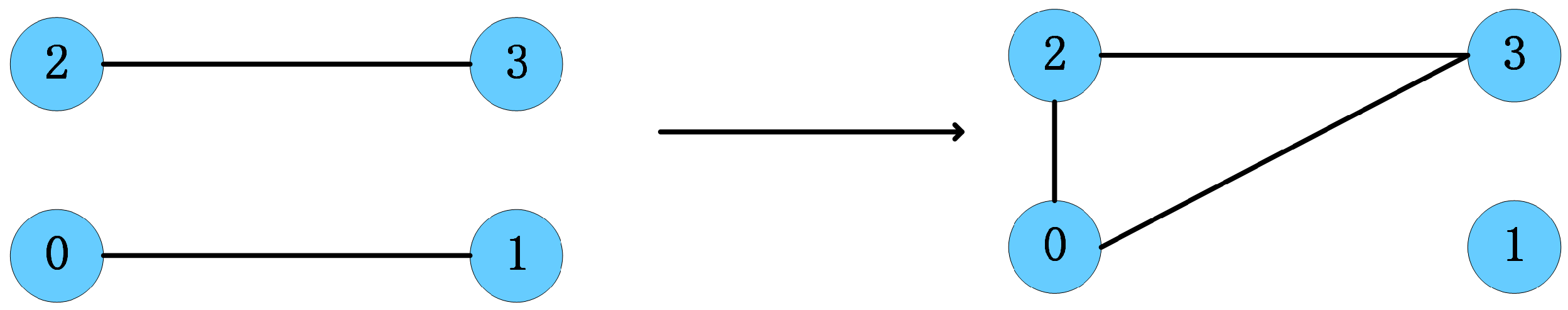
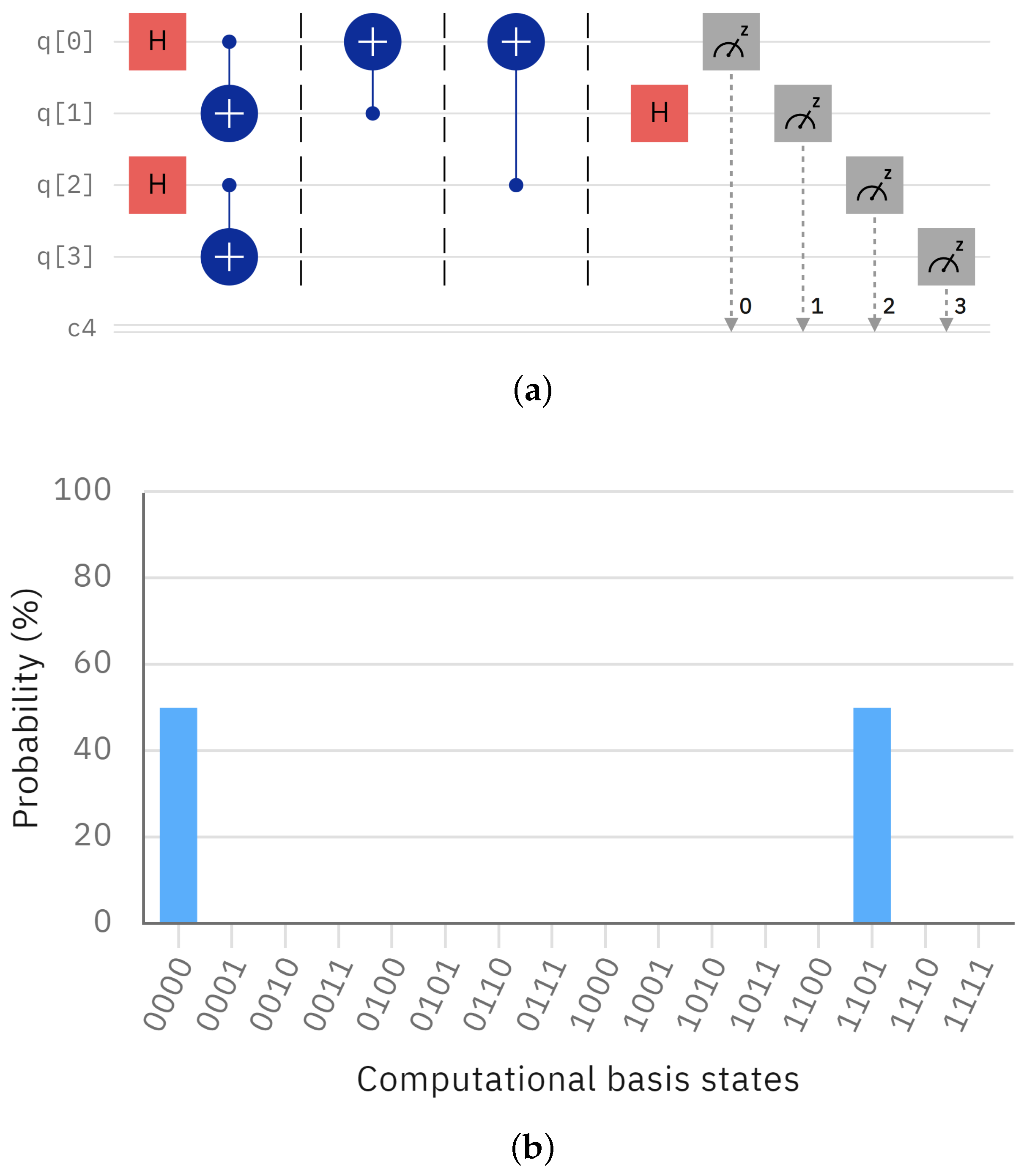
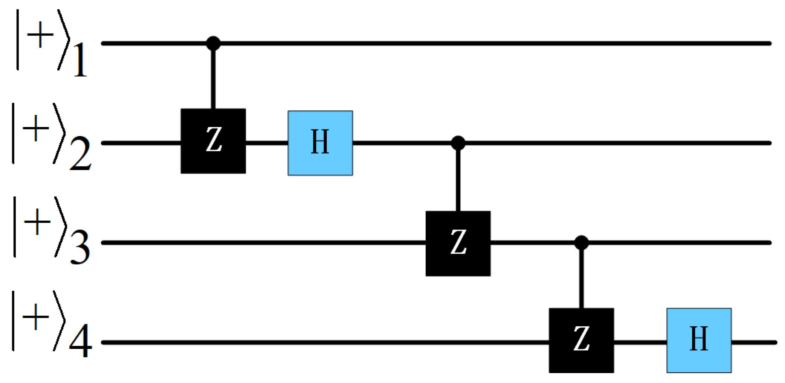
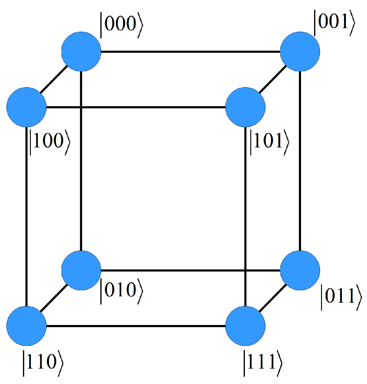
2.2. 4-Qubit Cluster States Generation
3. Generating Cluster States Using Quantum Gates Formed by Multi-Coin Quantum Walk
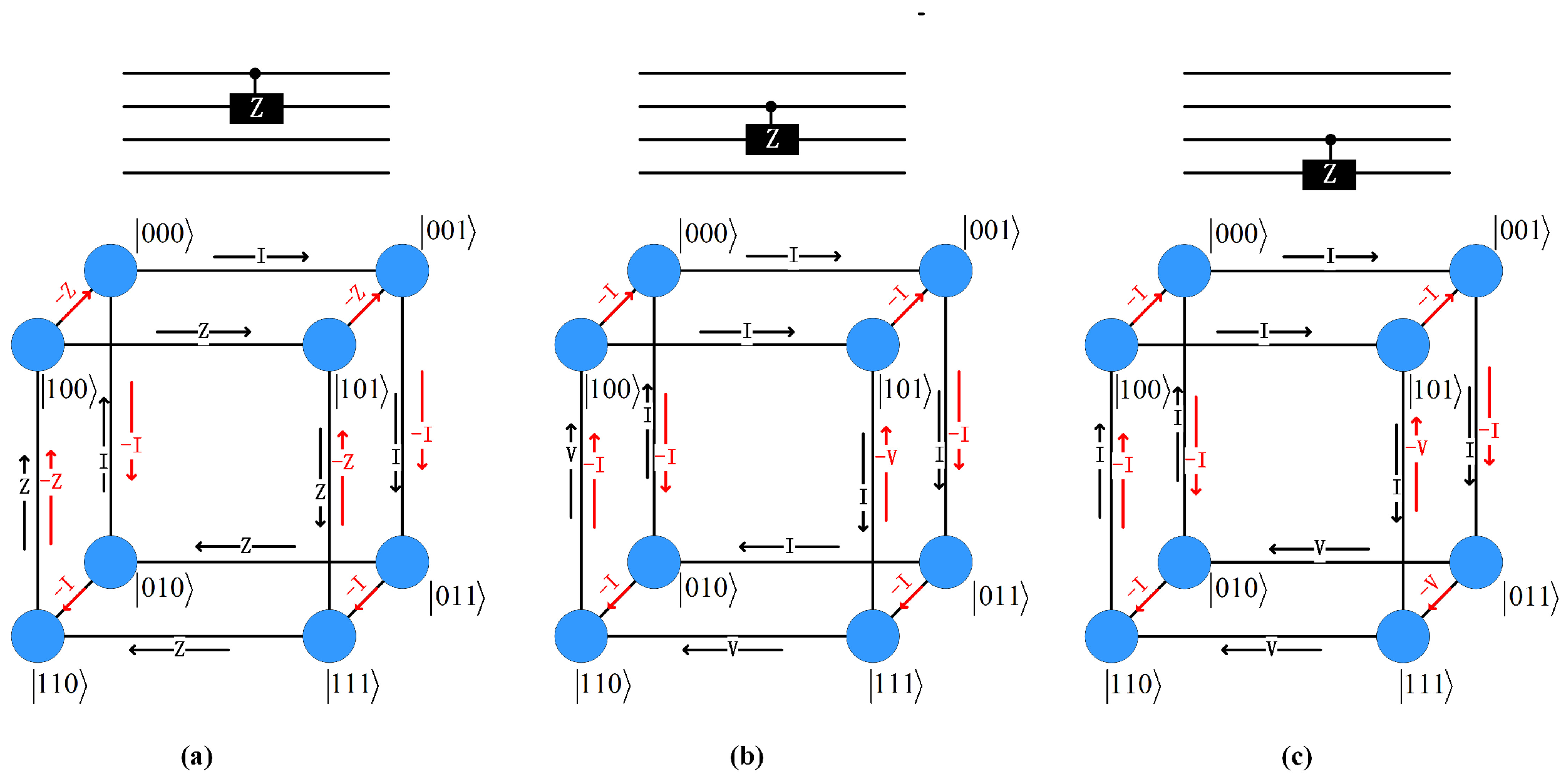
3.1. CZ Gate
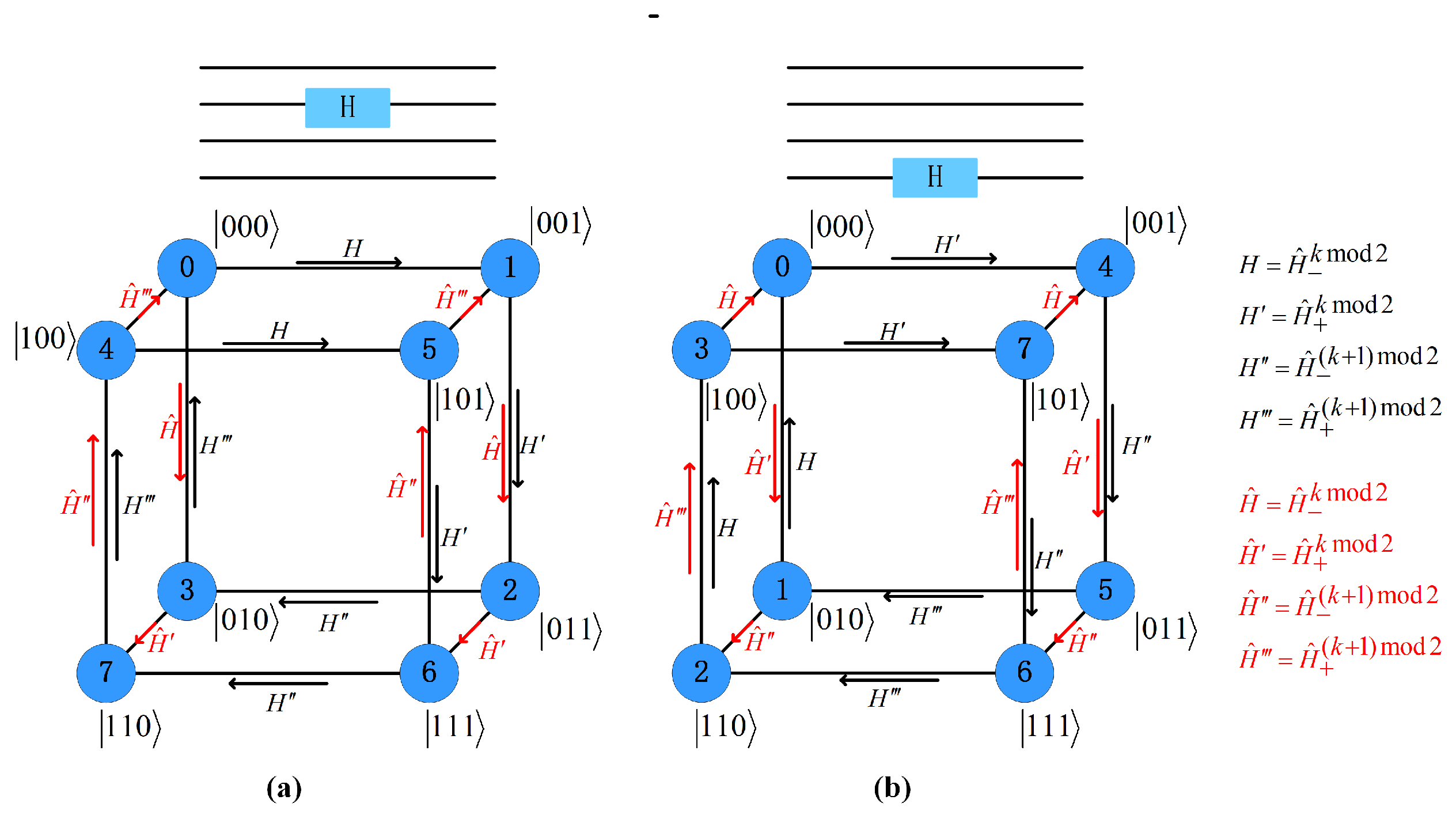
3.2. Hadamard Gate
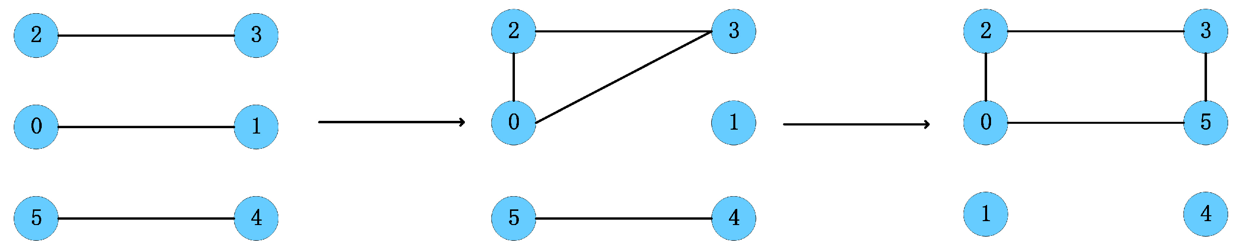
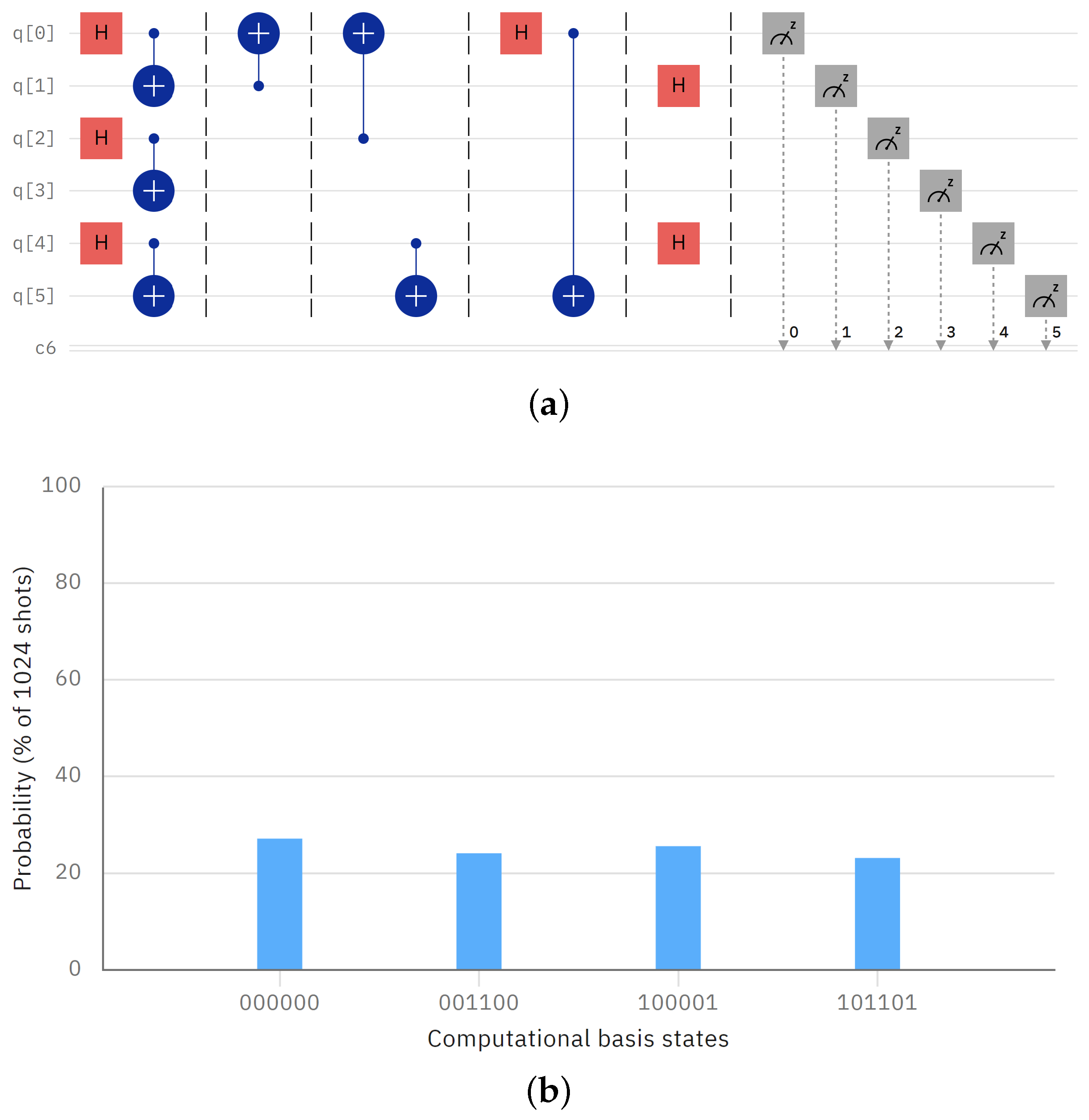
3.3. Generating Cluster States
4. Conclusions
Author Contributions
Funding
Institutional Review Board Statement
Informed Consent Statement
Data Availability Statement
Conflicts of Interest
References
- Raussendorf, R.; Briegel, H.J. A one-way quantum computer. Phys. Rev. Lett. 2001, 86, 5188. [Google Scholar] [CrossRef] [PubMed]
- Raussendorf, R.; Browne, D.E.; Briegel, H.J. Measurement-based quantum computation on cluster states. Phys. Rev. A 2003, 68, 022312. [Google Scholar] [CrossRef]
- Nielsen, M.A. Optical quantum computation using cluster states. Phys. Rev. Lett. 2004, 93, 040503. [Google Scholar] [CrossRef] [PubMed]
- Browne, D.E.; Rudolph, T. Resource-efficient linear optical quantum computation. Phys. Rev. Lett. 2005, 95, 010501. [Google Scholar] [CrossRef] [PubMed]
- Gilbert, G.; Hamrick, M.; Weinstein, Y.S. Efficient construction of photonic quantum-computational clusters. Phys. Rev. A 2006, 73, 064303. [Google Scholar] [CrossRef]
- Djordjevic, I.B. Quantum Information Processing, Quantum Computing, and Quantum Error Correction: An Engineering Approach Second Edition; Elsevier Inc.: Amsterdam, The Netherlands, 2021. [Google Scholar]
- Venegas-Andraca, S.E. Quantum walks: A comprehensive review. Quantum Inf. Process. 2012, 11, 1015–1106. [Google Scholar] [CrossRef]
- Kempe, J. Quantum random walks: An introductory overview. Contemp. Phys. 2003, 44, 307–327. [Google Scholar] [CrossRef]
- Lovett, N.B.; Cooper, S.; Everitt, M.; Trevers, M.; Kendon, V. Universal quantum computation using the discrete-time quantum walk. Phys. Rev. A 2010, 81, 042330. [Google Scholar] [CrossRef]
- Wang, J.; Manouchehri, K. Physical Implementation of Quantum Walks; Springer: Berlin/Heidelberg, Germany, 2014. [Google Scholar]
- Innocenti, L.; Majury, H.; Giordani, T.; Spagnolo, N.; Sciarrino, F.; Paternostro, M.; Ferraro, A. Quantum state engineering using one-dimensional discrete-time quantum walks. Phys. Rev. A 2017, 96, 062326. [Google Scholar] [CrossRef]
- Giordani, T.; Polino, E.; Emiliani, S.; Suprano, A.; Innocenti, L.; Majury, H.; Marrucci, L.; Paternostro, M.; Ferraro, A.; Spagnolo, N.; et al. Experimental engineering of arbitrary qudit states with discrete-time quantum walks. Phys. Rev. Lett. 2019, 122, 020503. [Google Scholar] [CrossRef] [PubMed] [Green Version]
- Li, X.M.; Yang, M.; Paunković, N.; Li, D.C.; Cao, Z.L. Entanglement swapping via three-step quantum walk-like protocol. Phys. Lett. A 2017, 381, 3875–3879. [Google Scholar] [CrossRef]
- Li, M.; Shang, Y. Entangled state generation via quantum walks with multiple coins. Npj Quantum Inf. 2021, 7, 70. [Google Scholar] [CrossRef]
- Singh, S.; Chawla, P.; Sarkar, A.; Chandrashekar, C. Universal quantum computing using single-particle discrete-time quantum walk. Sci. Rep. 2021, 11, 11551. [Google Scholar] [CrossRef] [PubMed]
- Wang, Y.; Shang, Y.; Xue, P. Generalized teleportation by quantum walks. Quantum Inf. Process. 2017, 16, 221. [Google Scholar] [CrossRef]
- Briegel, H.J.; Raussendorf, R. Persistent entanglement in arrays of interacting particles. Phys. Rev. Lett. 2001, 86, 910. [Google Scholar] [CrossRef] [PubMed]
- Zhang, Q.N.; Li, C.C.; Li, Y.H.; Nie, Y.Y. Quantum secure direct communication based on four-qubit cluster states. Int. J. Theor. Phys. 2013, 52, 22–27. [Google Scholar] [CrossRef]


Publisher’s Note: MDPI stays neutral with regard to jurisdictional claims in published maps and institutional affiliations. |
© 2022 by the authors. Licensee MDPI, Basel, Switzerland. This article is an open access article distributed under the terms and conditions of the Creative Commons Attribution (CC BY) license (https://creativecommons.org/licenses/by/4.0/).
Share and Cite
Wang, T.; Chen, X.; Liang, J. Four-Qubit Cluster States Generation through Multi-Coin Quantum Walk. Appl. Sci. 2022, 12, 8750. https://doi.org/10.3390/app12178750
Wang T, Chen X, Liang J. Four-Qubit Cluster States Generation through Multi-Coin Quantum Walk. Applied Sciences. 2022; 12(17):8750. https://doi.org/10.3390/app12178750
Chicago/Turabian StyleWang, Tianyi, Xiaoguang Chen, and Jianxiong Liang. 2022. "Four-Qubit Cluster States Generation through Multi-Coin Quantum Walk" Applied Sciences 12, no. 17: 8750. https://doi.org/10.3390/app12178750